JP2010516958A - Flow control valve - Google Patents
Flow control valve Download PDFInfo
- Publication number
- JP2010516958A JP2010516958A JP2009546318A JP2009546318A JP2010516958A JP 2010516958 A JP2010516958 A JP 2010516958A JP 2009546318 A JP2009546318 A JP 2009546318A JP 2009546318 A JP2009546318 A JP 2009546318A JP 2010516958 A JP2010516958 A JP 2010516958A
- Authority
- JP
- Japan
- Prior art keywords
- motor
- planetary gear
- gear
- flow control
- control valve
- Prior art date
- Legal status (The legal status is an assumption and is not a legal conclusion. Google has not performed a legal analysis and makes no representation as to the accuracy of the status listed.)
- Pending
Links
- 230000005540 biological transmission Effects 0.000 claims abstract description 25
- XLYOFNOQVPJJNP-UHFFFAOYSA-N water Substances O XLYOFNOQVPJJNP-UHFFFAOYSA-N 0.000 abstract description 15
- 238000003780 insertion Methods 0.000 description 8
- 230000037431 insertion Effects 0.000 description 8
- 238000010586 diagram Methods 0.000 description 5
- 238000012856 packing Methods 0.000 description 5
- 238000007792 addition Methods 0.000 description 1
- 230000000694 effects Effects 0.000 description 1
- 238000012986 modification Methods 0.000 description 1
- 230000004048 modification Effects 0.000 description 1
- 230000002093 peripheral effect Effects 0.000 description 1
- 238000006467 substitution reaction Methods 0.000 description 1
- 229920003002 synthetic resin Polymers 0.000 description 1
- 239000000057 synthetic resin Substances 0.000 description 1
Images
Classifications
-
- F—MECHANICAL ENGINEERING; LIGHTING; HEATING; WEAPONS; BLASTING
- F16—ENGINEERING ELEMENTS AND UNITS; GENERAL MEASURES FOR PRODUCING AND MAINTAINING EFFECTIVE FUNCTIONING OF MACHINES OR INSTALLATIONS; THERMAL INSULATION IN GENERAL
- F16K—VALVES; TAPS; COCKS; ACTUATING-FLOATS; DEVICES FOR VENTING OR AERATING
- F16K31/00—Actuating devices; Operating means; Releasing devices
- F16K31/02—Actuating devices; Operating means; Releasing devices electric; magnetic
- F16K31/04—Actuating devices; Operating means; Releasing devices electric; magnetic using a motor
- F16K31/047—Actuating devices; Operating means; Releasing devices electric; magnetic using a motor characterised by mechanical means between the motor and the valve, e.g. lost motion means reducing backlash, clutches, brakes or return means
-
- F—MECHANICAL ENGINEERING; LIGHTING; HEATING; WEAPONS; BLASTING
- F16—ENGINEERING ELEMENTS AND UNITS; GENERAL MEASURES FOR PRODUCING AND MAINTAINING EFFECTIVE FUNCTIONING OF MACHINES OR INSTALLATIONS; THERMAL INSULATION IN GENERAL
- F16K—VALVES; TAPS; COCKS; ACTUATING-FLOATS; DEVICES FOR VENTING OR AERATING
- F16K31/00—Actuating devices; Operating means; Releasing devices
- F16K31/44—Mechanical actuating means
- F16K31/53—Mechanical actuating means with toothed gearing
-
- G—PHYSICS
- G05—CONTROLLING; REGULATING
- G05D—SYSTEMS FOR CONTROLLING OR REGULATING NON-ELECTRIC VARIABLES
- G05D7/00—Control of flow
- G05D7/06—Control of flow characterised by the use of electric means
- G05D7/0617—Control of flow characterised by the use of electric means specially adapted for fluid materials
- G05D7/0629—Control of flow characterised by the use of electric means specially adapted for fluid materials characterised by the type of regulator means
- G05D7/0635—Control of flow characterised by the use of electric means specially adapted for fluid materials characterised by the type of regulator means by action on throttling means
-
- H—ELECTRICITY
- H02—GENERATION; CONVERSION OR DISTRIBUTION OF ELECTRIC POWER
- H02K—DYNAMO-ELECTRIC MACHINES
- H02K7/00—Arrangements for handling mechanical energy structurally associated with dynamo-electric machines, e.g. structural association with mechanical driving motors or auxiliary dynamo-electric machines
- H02K7/10—Structural association with clutches, brakes, gears, pulleys or mechanical starters
- H02K7/116—Structural association with clutches, brakes, gears, pulleys or mechanical starters with gears
-
- F—MECHANICAL ENGINEERING; LIGHTING; HEATING; WEAPONS; BLASTING
- F16—ENGINEERING ELEMENTS AND UNITS; GENERAL MEASURES FOR PRODUCING AND MAINTAINING EFFECTIVE FUNCTIONING OF MACHINES OR INSTALLATIONS; THERMAL INSULATION IN GENERAL
- F16H—GEARING
- F16H31/00—Other gearings with freewheeling members or other intermittently driving members
- F16H31/001—Mechanisms with freewheeling members
-
- F—MECHANICAL ENGINEERING; LIGHTING; HEATING; WEAPONS; BLASTING
- F16—ENGINEERING ELEMENTS AND UNITS; GENERAL MEASURES FOR PRODUCING AND MAINTAINING EFFECTIVE FUNCTIONING OF MACHINES OR INSTALLATIONS; THERMAL INSULATION IN GENERAL
- F16H—GEARING
- F16H37/00—Combinations of mechanical gearings, not provided for in groups F16H1/00 - F16H35/00
- F16H37/02—Combinations of mechanical gearings, not provided for in groups F16H1/00 - F16H35/00 comprising essentially only toothed or friction gearings
- F16H37/06—Combinations of mechanical gearings, not provided for in groups F16H1/00 - F16H35/00 comprising essentially only toothed or friction gearings with a plurality of driving or driven shafts; with arrangements for dividing torque between two or more intermediate shafts
- F16H37/065—Combinations of mechanical gearings, not provided for in groups F16H1/00 - F16H35/00 comprising essentially only toothed or friction gearings with a plurality of driving or driven shafts; with arrangements for dividing torque between two or more intermediate shafts with a plurality of driving or driven shafts
-
- F—MECHANICAL ENGINEERING; LIGHTING; HEATING; WEAPONS; BLASTING
- F16—ENGINEERING ELEMENTS AND UNITS; GENERAL MEASURES FOR PRODUCING AND MAINTAINING EFFECTIVE FUNCTIONING OF MACHINES OR INSTALLATIONS; THERMAL INSULATION IN GENERAL
- F16H—GEARING
- F16H37/00—Combinations of mechanical gearings, not provided for in groups F16H1/00 - F16H35/00
- F16H37/12—Gearings comprising primarily toothed or friction gearing, links or levers, and cams, or members of at least two of these types
- F16H37/124—Gearings comprising primarily toothed or friction gearing, links or levers, and cams, or members of at least two of these types for interconverting rotary motion and reciprocating motion
-
- H—ELECTRICITY
- H02—GENERATION; CONVERSION OR DISTRIBUTION OF ELECTRIC POWER
- H02K—DYNAMO-ELECTRIC MACHINES
- H02K16/00—Machines with more than one rotor or stator
Landscapes
- Engineering & Computer Science (AREA)
- General Engineering & Computer Science (AREA)
- Mechanical Engineering (AREA)
- Power Engineering (AREA)
- Physics & Mathematics (AREA)
- General Physics & Mathematics (AREA)
- Automation & Control Theory (AREA)
- Mechanically-Actuated Valves (AREA)
- Electrically Driven Valve-Operating Means (AREA)
Abstract
本発明は、加熱された水が流れる配管中において、ボイラから供給された加熱された水の流量を制御する流量制御弁に関する。2つの低価格1方向モータを使用して、正/逆回転して流量を制御し、かつ2つの1方向モータに接続された歯車アセンブリに簡単なクラッチ構造を適用することによって、別のモータが回転するとき1つのモータ用の動力を停止できる流量制御弁を提供する。本発明の実施形態に従った流量制御弁は、動力伝達シャフトを有し、かつ一方向に回転する第1モータ、および動力伝達シャフトを有し、かつ第1モータと反対方向に回転する第2モータを含むモータアセンブリと、動力を第1モータに伝達する第1遊星歯車、動力を第2モータに伝達する第2遊星歯車、および第1遊星歯車と第2遊星歯車との間に配置され、第1および第2遊星歯車に係合された太陽歯車を含み、かつ動力を伝達または停止するための、第1遊星歯車と第1モータとの間、ならびに第2遊星歯車と第2モータとの間にクラッチ構造を有する歯車アセンブリと、太陽歯車の回転によって上/下に往復動するシャフト、およびシャフトの下方部に適合し、かつ弁を開/閉する弁ユニットを含む弁アクチュエータとを含む。
【代表図】
The present invention relates to a flow rate control valve for controlling the flow rate of heated water supplied from a boiler in a pipe through which heated water flows. By using two low-cost one-way motors to control forward / reverse and flow control, and applying a simple clutch structure to the gear assembly connected to the two one-way motors, Provided is a flow control valve capable of stopping power for one motor when rotating. A flow control valve according to an embodiment of the present invention includes a first motor that has a power transmission shaft and rotates in one direction, and a second motor that has a power transmission shaft and rotates in a direction opposite to the first motor. A motor assembly including a motor, a first planetary gear that transmits power to the first motor, a second planetary gear that transmits power to the second motor, and the first planetary gear and the second planetary gear, Between the first planetary gear and the first motor, and between the second planetary gear and the second motor, including a sun gear engaged with the first and second planetary gears, and for transmitting or stopping power. A gear assembly having a clutch structure therebetween, a shaft that reciprocates up / down by rotation of the sun gear, and a valve actuator that includes a valve unit that fits the lower portion of the shaft and opens / closes the valve.
[Representative]
Description
本発明は流量制御弁に関し、加熱された水が流れる管路中の、ボイラから供給された加熱された水の流量を制御する流量制御弁に特に関する。 The present invention relates to a flow control valve, and particularly relates to a flow control valve that controls a flow rate of heated water supplied from a boiler in a pipeline through which heated water flows.
一般にボイラシステムは、加熱が必要とされる各部屋に加熱された水を分配する配水器を備えている。配水器は、ボイラの熱交換器によって加熱された水を水供給管を介して受容し、その後、加熱された水を各部屋に分配し、加熱された水は、部屋に熱エネルギーを伝達することによって冷却され、その後、戻り管を介して膨張タンクに送られる。配水器は、各部屋に供給された加熱された水の流量を制御するため流量制御弁を備えている。 In general, a boiler system includes a water distributor that distributes heated water to each room that needs to be heated. The water distributor receives the water heated by the boiler heat exchanger through the water supply pipe, and then distributes the heated water to each room, and the heated water transfers thermal energy to the room And then sent to an expansion tank via a return pipe. The water distributor includes a flow control valve for controlling the flow rate of the heated water supplied to each room.
技術的課題
チャンネルを開/閉する流量制御弁のために、正逆に回転できる2方向モータを使用することは高価ゆえ経済的ではない。
TECHNICAL PROBLEM It is not economical to use a bi-directional motor that can rotate forward and backward for a flow control valve that opens / closes a channel.
2つの低価格1方向モータを使用して正/逆転換可能で流量を制御する流量制御弁を提供することが本発明の目的である。また、2つの1方向モータに接続された歯車アセンブリに簡単なクラッチ構造を適用することで、モータのための動力(power)が停止可能であり、その間に別のモータが回転する流量制御弁を提供することが本発明の別の目的である。 It is an object of the present invention to provide a flow rate control valve that controls forward and reverse flow using two low cost one-way motors and controls the flow rate. In addition, by applying a simple clutch structure to the gear assembly connected to the two one-way motors, the power for the motor can be stopped, and a flow control valve for rotating another motor between them can be installed. It is another object of the present invention to provide.
技術的解決
本発明の局面に従うと、流量制御弁は、動力伝達シャフトを有し、かつ一方向に回転する第1モータ、および動力伝達シャフトを有し、かつ第1モータの逆方向に回転する第2モータを含むモータアセンブリと、第1モータに動力を伝達する第1遊星歯車、第2モータに動力を伝達する第2遊星歯車、ならびに第1遊星歯車と第2遊星歯車との間に配置され、第1および第2遊星歯車に係合された太陽歯車を含み、かつ動力を伝達または停止するための、第1遊星歯車と第1モータとの間および第2遊星歯車と第2モータとの間にクラッチ構造を有する歯車アセンブリと、太陽歯車の回転によって上/下に往復動するシャフト、およびシャフトの下方部に適合し、弁を開/閉する弁ユニットを含む弁アクチュエータとを含む。
TECHNICAL SOLUTION According to an aspect of the present invention, the flow control valve has a power transmission shaft and a first motor that rotates in one direction, and a power transmission shaft that rotates in the opposite direction of the first motor. A motor assembly including a second motor, a first planetary gear that transmits power to the first motor, a second planetary gear that transmits power to the second motor, and a first planetary gear and a second planetary gear disposed between the first planetary gear and the second planetary gear And includes a sun gear engaged with the first and second planetary gears and between the first planetary gear and the first motor and the second planetary gear and the second motor for transmitting or stopping power. A gear assembly having a clutch structure therebetween, a shaft that reciprocates up / down by rotation of the sun gear, and a valve actuator that includes a valve unit that conforms to the lower portion of the shaft and opens / closes the valve.
第1モータの動力伝達シャフトおよび第2モータの動力伝達シャフトから複数のロック部がそれぞれ突出してもよい。また、歯車アセンブリのクラッチ構造において、第1および第2モータのロック部ならびに第1遊星歯車および第2遊星歯車の上側に形成された連続鋸歯形状の突出部をロックすることおよび逃がすことにより、動力が伝達および停止されてもよい。 A plurality of lock portions may protrude from the power transmission shaft of the first motor and the power transmission shaft of the second motor, respectively. Further, in the clutch structure of the gear assembly, the locking portion of the first and second motors and the continuous sawtooth-shaped protruding portion formed on the upper side of the first planetary gear and the second planetary gear are locked and released, thereby May be transmitted and stopped.
ロック部が突出部上で上方に逃げるとき、第1遊星歯車および第2遊星歯車を弾性的に戻すため、第1遊星歯車および第2遊星歯車の下に弾性部材が配置されてもよい。 An elastic member may be disposed under the first planetary gear and the second planetary gear in order to elastically return the first planetary gear and the second planetary gear when the lock portion escapes upward on the protrusion.
カムが太陽歯車の下方側に形成されてもよい。また、弁アクチュエータが、太陽歯車のカム接触面と接触し、太陽歯車の回転によって上/下に往復動する下方カム接触面を有する下方カム部材、下方カム部材の下方側を弾性的に支持する弾性部材を含んでもよい。 A cam may be formed on the lower side of the sun gear. Further, the valve actuator is in contact with the cam contact surface of the sun gear and elastically supports the lower cam member having a lower cam contact surface that reciprocates up / down by the rotation of the sun gear, and the lower side of the lower cam member. An elastic member may be included.
下方カム部材が、下方カム部材の内側で上方に突出するガイド部材によってガイドされ、太陽歯車の回転と共に往復動してもよい。 The lower cam member may be guided by a guide member protruding upward inside the lower cam member, and may reciprocate with the rotation of the sun gear.
有利な効果
上記に詳述したように本発明の実施形態の流量制御弁に従って、1方向モータが使用され、クラッチ構造が提供され、簡単な構造の弁を達成し、2方向モータが使用される場合と比べて弁の価格を下げことが可能である。また、太陽歯車および下方カム部材の接触面がカム形状に形成されているので、弁の開量を制御することで流量を制御することが可能である。
Advantageous Effects As detailed above, according to the flow control valve of the embodiment of the present invention, a one-way motor is used, a clutch structure is provided, a simple structure valve is achieved, and a two-way motor is used. Compared to the case, the price of the valve can be lowered. Further, since the contact surfaces of the sun gear and the lower cam member are formed in a cam shape, the flow rate can be controlled by controlling the opening amount of the valve.
本発明の好適な実施形態に従った構成と動作を添付の図面を参照して以下に詳細に記載する。 The structure and operation according to preferred embodiments of the present invention will be described in detail below with reference to the accompanying drawings.
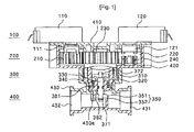
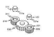
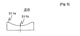
図1は、本発明の実施形態に従った流量制御弁の側面断面図であり、図2は、本発明の実施形態に従った歯車アセンブリおよびクラッチ部材を示す斜視図であり、図3は、図2の側面図であり、図4は、本発明の実施形態に従った弁アクチュエータを示す分解斜視図であり、図5は、図4の下方カム部材を示す側面図である。 FIG. 1 is a side sectional view of a flow control valve according to an embodiment of the present invention, FIG. 2 is a perspective view showing a gear assembly and a clutch member according to an embodiment of the present invention, and FIG. 2 is a side view of FIG. 2, FIG. 4 is an exploded perspective view showing a valve actuator according to an embodiment of the present invention, and FIG. 5 is a side view showing a lower cam member of FIG.
図1を参照して、モータアセンブリ100は、一方向に回転する第1モータ110および第1モータ110に対向して配置され第1モータ110の反対方向に回転する第2モータ120から構成されている。第1モータ110および第2モータ120として例えば低価格ACモータが使用されてよい。動力伝達シャフト111、121は、第1モータ110および第2モータ120からそれぞれ下方に突出して、モータから歯車アセンブリ200に動力を伝達する。
Referring to FIG. 1, the
複数のロック部111a、121aは、動力伝達シャフト111、121の下方側から突出し、第1遊星歯車210および第2遊星歯車220の上側に、クラッチの動作等としてロックされる。歯車は以下に記載する。
The plurality of
歯車アセンブリ200は、動力伝達のための、第1モータ110の動力伝達シャフト111に接続された第1遊星歯車210、動力伝達のための、第2モータ120の動力伝達シャフト121に接続された第2の遊星歯車220、およびこれらの間で弁アクチュエータ300にモータの回転力を伝達するための、第1遊星歯車210および第2遊星歯車220に係合された太陽歯車230から構成されている。
The
鋸歯形状の連続突出部211、221が、第1遊星歯車210および第2遊星歯車220の上側に形成されて、動力伝達シャフト111、121のロック部111a、121aをクラッチの動作等としてロックする。
Sawtooth-shaped
頂点211a、221aが突出部211、221の頂部に、および底部211b、221bが下方側に形成されている。底部211b、221bは、ロック部111a、121aを着座させるための所定の幅を有する。
The
所定の角度を有する傾斜211c、221cが、頂点211a、221aと底部211b、221bとの間に形成され、第1および第2遊星歯車210、220が回転しているとき、第1および第2モータ110、120に伝達される動力は、動力伝達シャフト111、121のロック部111a、121aの逃げによって停止する。
また、垂直面211d、221dは、傾斜211c、221cに対向して形成され、第1および第2モータ110、120が、第1遊星歯車210および第2遊星歯車220に動力を伝達するようなとき、ロック部111a、121aをロックする。
The
第1遊星歯車210および第2遊星歯車220の下方側は、バネ等の弾性部材240によって弾性的に支持されている。
The lower sides of the first
弁アクチュエータ300は、太陽歯車230の回転によって上/下に往復動するシャフト330、および弁を開/閉するための、シャフト330の下部に適合している弁ユニット350を含む。
The
太陽歯車230の回転でシャフト330を往復動するためには様々な構造が利用できるが、本実施形態に従っては、シャフト330は、太陽歯車230の下方側および弁アクチュエータ300の下方カム部材310に形成されたカム231のカム動作によって往復動する。
Although various structures can be used to reciprocate the
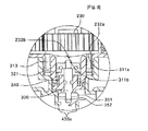
詳細には、カム231は、太陽歯車230の下方側から所定の長さにおいて突出し、カム形状に湾曲したカム接触面232がカム231の下方側の周縁に沿って形成されている。カム接触面232は、アーク形状面の最上点である2つの上死点232a、および上死点232aから最下点である2つの下死点232bを有する。
Specifically, the
また、カム231のカム接触面232の形状を取って、下方カム部材310の上側に下方カム接触面311が形成されている。下方カム接触面311は、上方に凹んだアーク形状面の最上点である2つの上死点311a、および上死点311aから最下点である2つの下死点311bを有する。
Further, a
従って、下方カム部材310は、上記のカム形状によって太陽歯車230の回転とともに上/下に往復動する。
Therefore, the
下方カム部材310において、端縁に沿って所定の距離で4つのガイドシャフト挿入孔312が形成され、シャフト挿入孔313が中央に形成されている。また、下方カム部材310の下方側は、バネ等の弾性部材340によって弾性的に支持されている。上記の構成に従って、下に動いた下方カム部材340が上に動くとき、弾性部材340は、弾性的戻り力を提供するように下方カム部材310の下方側に弾性力を上方に与える。
In the
上/下往復動する下方カム部材310は、ガイド部材320によってガイドされることが好ましい。ガイド部材320は、下方カム部材310のガイドシャフト挿入孔312に挿入される4つのガイドシャフト321を有し、弾性部材340が挿入される環状弾性部材挿入溝322がガイドシャフト321から内側に形成され、シャフト330が挿入されるシャフト貫通孔323が弾性部材挿入溝322から内側に形成されている。また、Oリングが嵌め合わされるOリング挿入溝324が、ガイド部材320の周縁に気密のため形成されている。
The
シャフト330は、上方および下方端部にそれぞれEリング371、372を挿入するためのEリング挿入溝330a、330c、ならびに気密のために中央部においてOリング382を挿入するためのOリング挿入溝330bを有する。
The
シャフト330の下方部に嵌め合わされる弁ユニット350は、合成樹脂で作製されたパッキング支持部材351、および弁座430aと接触する/弁座430aから離す、ことによって弁を開/閉するパッキング352から構成されている。パッキング352に使用されるのはゴムが好ましい。
The valve unit 350 fitted to the lower part of the
本体アセンブリ400は、この実施形態の最も外側に配置される。本体アセンブリ400は、太陽歯車230の上方側を覆う上部カバー410、第1および第2遊星歯車210、220の側面を覆う歯車側本体420、および弁アクチュエータ300の周縁を覆う弁側本体430から構成される。弁側本体430は、加熱された水の流入のための入口431および弁ユニット350を通過する加熱された水の流出のための出口432を有する。
The
本発明の実施形態に従ったクラッチ等の上記の構成の流量制御弁の動作を以下に記載する。説明の簡単のため、第1モータ110の回転方向が正方向であり、第2モータ120の回転方向が逆方向と仮定する。
The operation of the flow control valve having the above-described configuration such as a clutch according to the embodiment of the present invention will be described below. For simplicity of explanation, it is assumed that the rotation direction of the
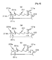
図6Aから6Cは、本発明の実施形態に従った遊星歯車および動力伝達シャフトのロック部の動作の図である。図6Aに示すように、第1モータ110が正方向に回転すると、動力伝達シャフト111のロック部111aは、矢印の方向に回転しつつ第1遊星歯車210の突出部211にロックされることで、第1遊星歯車210が同じ方向に回転し、動力が太陽歯車230に伝達される。
6A to 6C are diagrams of the operation of the planetary gear and the lock portion of the power transmission shaft according to an embodiment of the present invention. As shown in FIG. 6A, when the
太陽歯車230に伝達された動力は、太陽歯車230に係合された第2遊星歯車220に伝達される。図6Bおよび6Cに示すように、第2遊星歯車220は、矢印の方向に回転するが、底部221bと接触している動力伝達シャフト121のロック部121aは、傾斜221c上で頂点221aの方に逃げる。その結果、クラッチ等のこのような動作により第2モータ120に動力は伝達されない。ロック部121aの逃げにより下方に動いた第2遊星歯車220は、下方側を支持する弾性部材240によって戻される。
The power transmitted to the
また、第1モータ110が停止して第2モータ120が逆方向に回転すると、第2遊星歯車210、太陽歯車230、および第1遊星歯車210は、伝達された動力によって回転するが、第1遊星歯車210が回転中の場合は、動力伝達シャフト111のロック部111aが、第1遊星歯車210の突出部211の傾斜221cで上方に逃げる。その結果、クラッチ等のこのような動作により動力が第1モータ110に伝達される。
When the
図7および8は、本発明の実施形態に従って弁が開閉する様子を示す図である。 7 and 8 are diagrams showing how the valve opens and closes according to an embodiment of the present invention.
図7は、閉じた弁を示す。詳細には、太陽歯車230の両側に下死点232bが位置決めされ、下方カム部材310の上死点311aが太陽歯車230の下死点232bに接触している。従って、下方カム部材310は、太陽歯車230の下死点232bにより下に押されることで、シャフト330および弁ユニット350は下に動かされ、それによりパッキング352が弁座430aと接触して弁を閉じる。ここで太陽歯車230の上死点232aおよび下方カム部材310の下死点311bは間隔が空けられている。
FIG. 7 shows a closed valve. Specifically, the bottom
図8は、開いた弁を示す。詳細には、閉じた弁の図7に示すように、第1モータ110または第2モータ120が回転中の場合、太陽歯車230の下死点232bおよび下方カム部材310の下死点311b、ならびに太陽歯車230の上死点232aおよび下方カム部材310の上死点311aは互いにそれぞれ接触している。従って、弾性部材340の弾性力によって下方カム部材310が上に押されると、シャフト330および弁ユニット350が上に動かされ、パッキング352が弁座430aから離れることで弁が開放する。
FIG. 8 shows the open valve. Specifically, as shown in FIG. 7 of the closed valve, when the
弁は、図7で完全に(100%)閉じ、図8で完全に(100%)開放しているが、第1モータ110および第2モータ120の回転数を制御することで流量を制御し、弁の開量を制御することが可能である。
The valve is completely (100%) closed in FIG. 7 and fully (100%) open in FIG. 8, but the flow rate is controlled by controlling the rotational speeds of the
また、第1モータ110および第2モータ120が反対方向に回転するため、所望の流量に弁を制御することができる。すなわち、第1モータ110および第2モータ120の一方のみが提供されるとすると、開度50%から100%に変えるように、その後開度20%、弁を開度50%から20%へと変えるためにモータを回転させることが必要であり、従って弁の応答速度が低下する。しかし、本発明のこのような実施形態では2つのモータが提供されるので、50%開のとき他方のモータを逆方向に回転することによって20%開度を有するように弁を迅速に変えることが可能である。
Further, since the
本発明の好適な実施形態を例示目的のために開示してきたが、当業者は、添付の特許請求の範囲に開示された本発明の範囲と精神から逸脱することなく、様々な改変、追加、および置換が可能であることを理解するであろう。 While preferred embodiments of the present invention have been disclosed for purposes of illustration, those skilled in the art will recognize that various modifications, additions, and changes may be made without departing from the scope and spirit of the invention as disclosed in the appended claims. It will be understood that substitutions are possible.
産業上の利用可能性
本発明の実施形態に従って、2つの低価格1方向モータを使用して正/逆回転して流量を制御できる流量制御弁が提供される。
INDUSTRIAL APPLICABILITY In accordance with an embodiment of the present invention, a flow control valve is provided that can control flow by forward / reverse rotation using two low cost one way motors.
Claims (5)
前記第1モータに動力を伝達する第1遊星歯車、前記第2モータに動力を伝達する第2遊星歯車、ならびに前記第1遊星歯車と前記第2遊星歯車との間に配置され、前記第1および第2遊星歯車に係合された太陽歯車を含み、かつ動力を伝達または停止するための、前記第1遊星歯車と前記第1モータとの間および前記第2遊星歯車と前記第2モータとの間にクラッチ構造を有する歯車アセンブリと、
前記太陽歯車の回転によって上/下に往復動するシャフト、および前記シャフトの下方部に適合し、前記弁を開/閉する弁ユニットを含む弁アクチュエータと、
を備える流量制御弁。 A motor assembly including a first motor having a power transmission shaft and rotating in one direction; and a second motor having a power transmission shaft and rotating in a direction opposite to the first motor;
A first planetary gear that transmits power to the first motor; a second planetary gear that transmits power to the second motor; and the first planetary gear disposed between the first planetary gear and the second planetary gear; And a sun gear engaged with the second planetary gear and between the first planetary gear and the first motor and between the second planetary gear and the second motor for transmitting or stopping power. A gear assembly having a clutch structure between
A valve actuator including a shaft that reciprocates up / down by rotation of the sun gear, and a valve unit that fits a lower portion of the shaft and opens / closes the valve;
A flow control valve comprising:
かつ、前記歯車アセンブリのクラッチ構造において、前記第1および第2モータのロック部ならびに前記第1遊星歯車および前記第2遊星歯車の上側に形成された連続鋸歯形状の突出部をロックすることおよび逃がすことにより、前記動力が伝達および停止される、請求項1に記載の流量制御弁。 A plurality of lock portions protrude from the power transmission shaft of the first motor and the power transmission shaft of the second motor, respectively.
And in the clutch structure of the gear assembly, the locking portions of the first and second motors and the continuous sawtooth-shaped protrusions formed on the upper sides of the first planetary gear and the second planetary gear are locked and released. The flow control valve according to claim 1, wherein the power is transmitted and stopped.
前記弁アクチュエータが、前記太陽歯車のカム接触面と接触し、前記太陽歯車の回転によって上/下に往復動する下方カム接触面を有する下方カム部材を含み、かつ弾性部材が前記下方カム部材の下方側を弾性的に支持する、請求項1に記載の流量制御弁。 A cam protrudes from the lower side of the sun gear, and a cam-shaped cam contact surface is formed on the lower side of the cam.
The valve actuator includes a lower cam member having a lower cam contact surface that contacts a cam contact surface of the sun gear and reciprocates up / down by rotation of the sun gear, and an elastic member of the lower cam member The flow control valve according to claim 1, wherein the lower side is elastically supported.
Applications Claiming Priority (2)
| Application Number | Priority Date | Filing Date | Title |
|---|---|---|---|
| KR1020070006244A KR100838025B1 (en) | 2007-01-19 | 2007-01-19 | Flow control valve |
| PCT/KR2008/000260 WO2008088166A1 (en) | 2007-01-19 | 2008-01-16 | Flow control valve |
Publications (2)
| Publication Number | Publication Date |
|---|---|
| JP2010516958A true JP2010516958A (en) | 2010-05-20 |
| JP2010516958A5 JP2010516958A5 (en) | 2012-10-18 |
Family
ID=39636130
Family Applications (1)
| Application Number | Title | Priority Date | Filing Date |
|---|---|---|---|
| JP2009546318A Pending JP2010516958A (en) | 2007-01-19 | 2008-01-16 | Flow control valve |
Country Status (6)
| Country | Link |
|---|---|
| US (1) | US8231103B2 (en) |
| EP (1) | EP2109729A1 (en) |
| JP (1) | JP2010516958A (en) |
| KR (1) | KR100838025B1 (en) |
| CN (1) | CN101611253B (en) |
| WO (1) | WO2008088166A1 (en) |
Cited By (2)
| Publication number | Priority date | Publication date | Assignee | Title |
|---|---|---|---|---|
| JP2014503059A (en) * | 2011-01-20 | 2014-02-06 | 上▲海▼高迪▲亜▼▲電▼子系▲統▼有限公司 | Hard seal plug valve |
| JP7549192B2 (en) | 2020-06-02 | 2024-09-11 | タイガー魔法瓶株式会社 | Pressure Regulator |
Families Citing this family (13)
| Publication number | Priority date | Publication date | Assignee | Title |
|---|---|---|---|---|
| JP4497040B2 (en) * | 2005-07-08 | 2010-07-07 | 日立工機株式会社 | Vibration drill |
| FI121609B (en) * | 2009-06-11 | 2011-01-31 | Pekka Leskinen | Method and apparatus for accurate control of fluid flow |
| US8100141B2 (en) * | 2010-05-27 | 2012-01-24 | Slupecki Raymond H | Water supply control assembly with automatic shut-off and duty cycle reset |
| IT1402891B1 (en) * | 2010-11-23 | 2013-09-27 | Dana Italia Spa | TRANSMISSION GROUP PERFECTED FOR VEHICLES AND VEHICLES EQUIPPED WITH SUCH TRANSMISSION UNIT |
| ES2633164T3 (en) * | 2013-06-27 | 2017-09-19 | Airbus Defence And Space Limited | A swivel assembly |
| CN106838379B (en) * | 2015-12-07 | 2020-09-29 | 浙江三花制冷集团有限公司 | Electric switching valve |
| KR101724235B1 (en) | 2016-06-22 | 2017-04-18 | 신의엔텍(주) | Actuator |
| CN108443566A (en) * | 2018-04-28 | 2018-08-24 | 天津祥嘉流体控制系统有限公司 | A kind of underwater valve actuator |
| KR101986456B1 (en) | 2018-07-17 | 2019-06-05 | 한국수력원자력 주식회사 | Pipe locking apparatus |
| IT201800010254A1 (en) * | 2018-11-12 | 2020-05-12 | Robertshaw S R L | DEVICE TO ACTIVATE A FLOW DIVERTER |
| CN110145627B (en) * | 2019-06-24 | 2024-04-02 | 成都中科智成科技有限责任公司 | Axial slip structure of motor valve opening and closing mechanism |
| CN114458808B (en) * | 2022-02-14 | 2024-03-22 | 杭州先锋电子技术股份有限公司 | Double-clutch transmission mechanism |
| CN114183576B (en) * | 2022-02-14 | 2022-04-26 | 杭州先锋电子技术股份有限公司 | Electric valve with double transmission mechanisms |
Citations (8)
| Publication number | Priority date | Publication date | Assignee | Title |
|---|---|---|---|---|
| US3258985A (en) * | 1964-03-23 | 1966-07-05 | Jordan Controls Inc | Control apparatus for valve actuator |
| US3434025A (en) * | 1966-08-23 | 1969-03-18 | Northern Electric Co | Drive system employing dual motors |
| JPS5740184A (en) * | 1980-07-28 | 1982-03-05 | Anchor Darling Ind | Automatic dual mode valve actuator |
| JPS61193269U (en) * | 1985-05-24 | 1986-12-01 | ||
| JPH04232894A (en) * | 1990-07-30 | 1992-08-21 | General Electric Co <Ge> | Brake assembly for control rod drive apparatus |
| JPH0579151U (en) * | 1992-03-31 | 1993-10-26 | 東陶機器株式会社 | Electric valve for water supply |
| JPH0738844U (en) * | 1993-12-20 | 1995-07-14 | 株式会社松井製作所 | A valve that operates when the power is turned off |
| JPH10205639A (en) * | 1997-01-24 | 1998-08-04 | Kitz Corp | Actuator for valve |
Family Cites Families (17)
| Publication number | Priority date | Publication date | Assignee | Title |
|---|---|---|---|---|
| DE3501477A1 (en) * | 1985-01-15 | 1986-07-17 | Jaroslav Dipl.-Ing. 1000 Berlin Tecinsky | Device for the automatic control of the movement of the valve control rod of motor-operated high-performance valves |
| JPS61193269A (en) | 1985-02-22 | 1986-08-27 | Hitachi Ltd | Satellite image correction processing system |
| US4749004A (en) * | 1987-05-06 | 1988-06-07 | The Boeing Company | Airflow control valve having single inlet and multiple outlets |
| US4800308A (en) | 1988-03-21 | 1989-01-24 | Eti Systems | Motorized control unit with torsional elastomeric bias |
| CN1046591A (en) * | 1989-04-20 | 1990-10-31 | 胡耿 | Have the additional fire hose that revolves handle |
| JPH0579151A (en) | 1991-09-24 | 1993-03-30 | Inax Corp | Erecting method for plate-like architectural material |
| DE59301003D1 (en) * | 1992-09-02 | 1996-01-04 | Wilhelm A Keller | Electrically operated discharge device. |
| CN1092849A (en) * | 1993-03-22 | 1994-09-28 | 吴爱斌 | A kind of electric device for valve |
| JPH0738844A (en) | 1993-07-16 | 1995-02-07 | Canon Inc | Magnetic recording and reproducing device |
| CN2177140Y (en) * | 1993-12-14 | 1994-09-14 | 梁怀成 | Self seal multifunction water saving valve |
| KR0147593B1 (en) * | 1994-07-07 | 1998-10-01 | 김광호 | A drain apparatus of a washing machine |
| FR2772429B1 (en) * | 1997-12-16 | 2000-06-02 | Sagem | CONTROL VALVE FOR AN EXHAUST GAS RECIRCULATION SYSTEM OF AN INTERNAL COMBUSTION ENGINE |
| CN2427694Y (en) * | 2000-05-30 | 2001-04-25 | 张俊山 | Electric motor valve |
| KR200247276Y1 (en) * | 2001-06-26 | 2001-10-17 | 주식회사 한 에너지 시스템 | Apparatus for opening and closing valve |
| KR200350996Y1 (en) | 2004-02-05 | 2004-05-17 | 한국에이오씨(주) | 3-way valve |
| US7607638B2 (en) * | 2005-03-08 | 2009-10-27 | Borgwarner Inc. | EGR valve having rest position |
| KR200432718Y1 (en) | 2006-09-14 | 2006-12-07 | 주식회사 에스피일레멕 | opening and shutting equipment of valve |
-
2007
- 2007-01-19 KR KR1020070006244A patent/KR100838025B1/en active IP Right Grant
-
2008
- 2008-01-16 EP EP08704799A patent/EP2109729A1/en not_active Withdrawn
- 2008-01-16 CN CN2008800026517A patent/CN101611253B/en not_active Expired - Fee Related
- 2008-01-16 JP JP2009546318A patent/JP2010516958A/en active Pending
- 2008-01-16 WO PCT/KR2008/000260 patent/WO2008088166A1/en active Application Filing
- 2008-01-16 US US12/523,727 patent/US8231103B2/en not_active Expired - Fee Related
Patent Citations (8)
| Publication number | Priority date | Publication date | Assignee | Title |
|---|---|---|---|---|
| US3258985A (en) * | 1964-03-23 | 1966-07-05 | Jordan Controls Inc | Control apparatus for valve actuator |
| US3434025A (en) * | 1966-08-23 | 1969-03-18 | Northern Electric Co | Drive system employing dual motors |
| JPS5740184A (en) * | 1980-07-28 | 1982-03-05 | Anchor Darling Ind | Automatic dual mode valve actuator |
| JPS61193269U (en) * | 1985-05-24 | 1986-12-01 | ||
| JPH04232894A (en) * | 1990-07-30 | 1992-08-21 | General Electric Co <Ge> | Brake assembly for control rod drive apparatus |
| JPH0579151U (en) * | 1992-03-31 | 1993-10-26 | 東陶機器株式会社 | Electric valve for water supply |
| JPH0738844U (en) * | 1993-12-20 | 1995-07-14 | 株式会社松井製作所 | A valve that operates when the power is turned off |
| JPH10205639A (en) * | 1997-01-24 | 1998-08-04 | Kitz Corp | Actuator for valve |
Cited By (2)
| Publication number | Priority date | Publication date | Assignee | Title |
|---|---|---|---|---|
| JP2014503059A (en) * | 2011-01-20 | 2014-02-06 | 上▲海▼高迪▲亜▼▲電▼子系▲統▼有限公司 | Hard seal plug valve |
| JP7549192B2 (en) | 2020-06-02 | 2024-09-11 | タイガー魔法瓶株式会社 | Pressure Regulator |
Also Published As
| Publication number | Publication date |
|---|---|
| WO2008088166A1 (en) | 2008-07-24 |
| US8231103B2 (en) | 2012-07-31 |
| CN101611253A (en) | 2009-12-23 |
| EP2109729A1 (en) | 2009-10-21 |
| CN101611253B (en) | 2011-11-30 |
| US20100096573A1 (en) | 2010-04-22 |
| KR100838025B1 (en) | 2008-06-12 |
Similar Documents
| Publication | Publication Date | Title |
|---|---|---|
| JP2010516958A (en) | Flow control valve | |
| US20150316156A1 (en) | Flow passage switching valve | |
| KR100831163B1 (en) | Temperature control valve capable of regulating flow rate delicately | |
| CN101135395A (en) | Mixed valve | |
| JPH0722326Y2 (en) | Heating system | |
| EP2565502B1 (en) | Tap for water supply pipes | |
| KR101724235B1 (en) | Actuator | |
| KR200450977Y1 (en) | The separation heating controller for heating mat | |
| CN101999104B (en) | Valves | |
| CN213479273U (en) | Water control valve | |
| KR100801127B1 (en) | Electromotive three-way valve | |
| JP2019199921A (en) | Three-way switching valve | |
| KR200247276Y1 (en) | Apparatus for opening and closing valve | |
| KR100714503B1 (en) | hot water distributor's temperature regulation valve | |
| HU230570B1 (en) | Single-lever mixing faucet with augmented angular interval | |
| JP2008291984A (en) | Valve device | |
| KR100734523B1 (en) | A hot water distributor with header and valve one body type | |
| KR20110071369A (en) | A 3way-valve for possible rotation manual | |
| CN220205709U (en) | Steam generating device and household appliance | |
| KR100972742B1 (en) | Hot-water control valve | |
| CN108368940B (en) | Gas valve for combustion device | |
| KR101189971B1 (en) | A valve driver of stroke variable type | |
| KR200314115Y1 (en) | Improved water supply valve | |
| KR200397705Y1 (en) | Hot water boiler using frictional heat | |
| RU2804374C1 (en) | Bypass valve |
Legal Events
| Date | Code | Title | Description |
|---|---|---|---|
| A621 | Written request for application examination |
Free format text: JAPANESE INTERMEDIATE CODE: A621 Effective date: 20100401 |
|
| A131 | Notification of reasons for refusal |
Free format text: JAPANESE INTERMEDIATE CODE: A131 Effective date: 20120221 |
|
| A601 | Written request for extension of time |
Free format text: JAPANESE INTERMEDIATE CODE: A601 Effective date: 20120521 |
|
| A602 | Written permission of extension of time |
Free format text: JAPANESE INTERMEDIATE CODE: A602 Effective date: 20120528 |
|
| A601 | Written request for extension of time |
Free format text: JAPANESE INTERMEDIATE CODE: A601 Effective date: 20120620 |
|
| A602 | Written permission of extension of time |
Free format text: JAPANESE INTERMEDIATE CODE: A602 Effective date: 20120627 |
|
| A601 | Written request for extension of time |
Free format text: JAPANESE INTERMEDIATE CODE: A601 Effective date: 20120720 |
|
| A602 | Written permission of extension of time |
Free format text: JAPANESE INTERMEDIATE CODE: A602 Effective date: 20120727 |
|
| A521 | Request for written amendment filed |
Free format text: JAPANESE INTERMEDIATE CODE: A523 Effective date: 20120821 |
|
| A524 | Written submission of copy of amendment under article 19 pct |
Free format text: JAPANESE INTERMEDIATE CODE: A524 Effective date: 20120821 |
|
| A131 | Notification of reasons for refusal |
Free format text: JAPANESE INTERMEDIATE CODE: A131 Effective date: 20130305 |
|
| A02 | Decision of refusal |
Free format text: JAPANESE INTERMEDIATE CODE: A02 Effective date: 20130730 |
