JP2010513927A - Object measurement method and system - Google Patents
Object measurement method and system Download PDFInfo
- Publication number
- JP2010513927A JP2010513927A JP2009543020A JP2009543020A JP2010513927A JP 2010513927 A JP2010513927 A JP 2010513927A JP 2009543020 A JP2009543020 A JP 2009543020A JP 2009543020 A JP2009543020 A JP 2009543020A JP 2010513927 A JP2010513927 A JP 2010513927A
- Authority
- JP
- Japan
- Prior art keywords
- distance sensor
- scan
- cutting tool
- optical sensor
- periscope
- Prior art date
- Legal status (The legal status is an assumption and is not a legal conclusion. Google has not performed a legal analysis and makes no representation as to the accuracy of the status listed.)
- Pending
Links
Images


Classifications
-
- G—PHYSICS
- G01—MEASURING; TESTING
- G01B—MEASURING LENGTH, THICKNESS OR SIMILAR LINEAR DIMENSIONS; MEASURING ANGLES; MEASURING AREAS; MEASURING IRREGULARITIES OF SURFACES OR CONTOURS
- G01B11/00—Measuring arrangements characterised by the use of optical techniques
- G01B11/24—Measuring arrangements characterised by the use of optical techniques for measuring contours or curvatures
Landscapes
- Physics & Mathematics (AREA)
- General Physics & Mathematics (AREA)
- Length Measuring Devices By Optical Means (AREA)
- Length Measuring Devices With Unspecified Measuring Means (AREA)
Abstract
物体を測定する方法は、物体を移動可能なステージに位置づける方法と、距離センサーで物体の回転スキャンを行う工程と、回転スキャンに基づいて物体の幾何学的パラメーターを測定する工程と、を含む。
【選択図】図2The method of measuring an object includes a method of positioning the object on a movable stage, a step of performing a rotational scan of the object with a distance sensor, and a step of measuring a geometric parameter of the object based on the rotational scan.
[Selection] Figure 2
Description
本発明は一般的に測定システムに関するものであり、また特に切削工具測定のための方法及びシステムに関する。 The present invention relates generally to measurement systems, and more particularly to methods and systems for cutting tool measurement.
切削工具は、エンジン翼などの航空機部品の製造において使用される重要な一部品である。少なくともいくつかの既知の切削工具は、複雑な幾何学的形状及び鋭角及び/又は曲線縁を有して製造される。そのようなことから、その切削工具の製造時における品質管理の維持は、その切削工具を使用して製造される部品の品質を管理するために最も重要であろう。具体的には、複数の工具が複数の同型のエンジン翼を製造するために用いられる場合、各切削工具は正確に調整された外形及び寸法で製造されることが必須である。しかしながら、既知の製造技術では、大抵の切削工具は必ずしも正確に検査され又はコントロールされて寸法及び外形で製造されているとは限らない。従って、少なくともいくつかの既知のエンジン翼は異なった寸法及び外形に製造される場合がある。 Cutting tools are an important part used in the manufacture of aircraft parts such as engine wings. At least some known cutting tools are manufactured with complex geometries and acute angles and / or curved edges. As such, maintaining quality control during the manufacture of the cutting tool will be most important for managing the quality of the parts manufactured using the cutting tool. Specifically, when a plurality of tools are used to manufacture a plurality of identical engine blades, it is essential that each cutting tool be manufactured with a precisely adjusted outer shape and dimensions. However, with known manufacturing techniques, most cutting tools are not always accurately inspected or controlled and manufactured in size and outline. Thus, at least some known engine wings may be manufactured to different dimensions and outlines.
例えば、図1は切削工具の製造において使用されるための設計モデル及びその設計モデルに基づいて製造される二例の切削工具を描写した図である。より具体的には、図1(a)は第一研削機械で製造された切削工具であり、図1(b)は第二研削機械で製造された切削工具であり、図1(c)は切削工具用の設計モデルである。図1で見られるように、切削工具は大抵設計モデルと異なる外形及び寸法で製造される。より具体的には、第一研削機械で製造された切削工具は、第二研削機械で製造された切削工具と異なる外形及び寸法を有する場合がある。 For example, FIG. 1 depicts a design model for use in manufacturing a cutting tool and two examples of cutting tools manufactured based on the design model. More specifically, FIG. 1A is a cutting tool manufactured by a first grinding machine, FIG. 1B is a cutting tool manufactured by a second grinding machine, and FIG. It is a design model for a cutting tool. As can be seen in FIG. 1, cutting tools are often manufactured with different outlines and dimensions than the design model. More specifically, the cutting tool manufactured by the first grinding machine may have a different external shape and dimensions than the cutting tool manufactured by the second grinding machine.
従って、同一性を確保するために切削工具を検査することが一般的である。より具体的には、各切削工具のパラメーターは大抵、画一性を確保するために品質基準に対して設計モデルにより測定及び検証される。しかしながら、既知の測定システムは二次元で切削工具のみを測定する、つまり既知の測定システムは、同時に切削工具のほんのわずかなパラメーター及び一つの特徴の測定に限られている。このように、その測定は信頼できるものではなく、時間ばかりがかかる場合がある。更に、既知の測定システムは通常複数の手動操作を必要とするため、測定の再現性が限られることがある。 Therefore, it is common to inspect cutting tools to ensure identity. More specifically, the parameters of each cutting tool are usually measured and verified by design models against quality standards to ensure uniformity. However, known measuring systems measure only cutting tools in two dimensions, ie known measuring systems are limited to measuring only a few parameters and one characteristic of the cutting tool at the same time. As such, the measurement is not reliable and may only take time. In addition, known measurement systems typically require multiple manual operations, which can limit the reproducibility of measurements.
一つの観点において、物体を測定する方法は移動可能なステージ上で物体を位置づける工程と、距離センサーで物体の回転スキャンを行う工程と、その回転スキャンに基づいて物体の幾何学的パラメーターを測定する工程と、を含む。 In one aspect, a method for measuring an object includes positioning an object on a movable stage, performing a rotational scan of the object with a distance sensor, and measuring a geometric parameter of the object based on the rotational scan. And a process.
更に他の観点において、物体を測定する方法は、物体の幾何学的パラメーターを測定するために物体の回転スキャンを行うための距離センサー及び物体を保持するための移動可能なステージを含む。更に他の観点において、既知のヘリカル構成で物体をスキャンする方法は、物体のヘリカルスキャン動作でスキャンされてもよい。 In yet another aspect, a method for measuring an object includes a distance sensor for performing a rotational scan of the object to measure a geometric parameter of the object and a movable stage for holding the object. In yet another aspect, a method for scanning an object with a known helical configuration may be scanned with a helical scan operation of the object.
更に他の観点において、物体の幾何学的パラメーターを測定するために物体の回転スキャンを行うための距離センサーが提供される。距離センサーは、光学センサー及びその光学センサーに接続されるペリスコープを含む。光学センサー及びペリスコープの少なくとも一つは、回転するように構成される。距離センサーは物体に関連して動くように構成される。 In yet another aspect, a distance sensor is provided for performing a rotational scan of an object to measure the geometric parameters of the object. The distance sensor includes an optical sensor and a periscope connected to the optical sensor. At least one of the optical sensor and the periscope is configured to rotate. The distance sensor is configured to move relative to the object.
本発明は、物体の測定に使用される代表的な方法及びシステムを提供する。特に、代表的な実施形態において、システムは物体の回転スキャンを行うための距離センサーと、物体を保持するための移動可能なステージとを有する。更に、距離センサーは光学センサー及びその光学センサーに接続されたペリスコープを含む。光学センサーとペリスコープとの少なくとも一つは、回転するように構成される。従って、システムはポイントクラウドデータの収集を容易にするために物体をヘリカルスキャンし、測定の再現性が容易にされた方法で自動的に物体の各パラメーターを測定する方法を供給する。 The present invention provides exemplary methods and systems used for measuring objects. In particular, in an exemplary embodiment, the system includes a distance sensor for performing a rotational scan of the object and a movable stage for holding the object. The distance sensor further includes an optical sensor and a periscope connected to the optical sensor. At least one of the optical sensor and the periscope is configured to rotate. Accordingly, the system provides a method of helically scanning an object to facilitate the collection of point cloud data and automatically measuring each parameter of the object in a manner that facilitates measurement reproducibility.
本発明は、測定切削工具に関連した本明細書を参照して以下に説明される。本発明は当業者にとって明瞭であり、また的確な変更を条件として教訓によって導かれるべきである。本発明のシステム及び方法は、航空エンジン部品などを含むいかなる物体の測定にも適している。 The present invention is described below with reference to this specification in connection with a measuring cutting tool. The present invention is clear to those skilled in the art and should be guided by lessons subject to precise modifications. The system and method of the present invention is suitable for measuring any object including aircraft engine parts and the like.
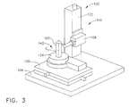
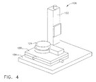
図2は切削工具102の測定に使用されてもよい代表的なシステム100の図である。具体的に、図2は切削工具102の端140を測定するために配置されたシステム100の図である。図3は、システム100を他の視点から見た図である。具体的に、図3は切削工具102の側面142をスキャンするために配置されたシステム100を示す。代表的な実施形態において、システム100はベース104と、ステージ106と、距離センサー108とを含む。図4は、ステージ106の図であり、図5は距離センサー108の概略図である。
FIG. 2 is a diagram of an
図示されてはいないが、当業者には当然なことながら、代表的な実施形態において、システム100はデータを保管及び分析するために、コンピュータ、データベース、及び/又はプロセッサの少なくとも一つに電気的に接続されている。更に代表的な実施形態において、システム100はデータを表示するために少なくとも一つのモニター(図示せず)に電気的に接続されている。
Although not shown, it will be appreciated by those skilled in the art that in an exemplary embodiment,
代表的な実施形態において、ステージ106はベース104に対して移動可能であり、また代表的な実施形態において、第一ステージ120及び第二ステージ122を含む。第一ステージ120は、その上に切削工具102を保持するために配置される。より具体的には、代表的な実施形態において、第一ステージ120は、その上に切削工具102を保持するために配置される回転軸124を含む。より具体的には、代表的な実施形態において、システム100は、約0ミリメートルから約200ミリメートルの範囲内の長さL1を有するいかなる切削工具102をその上に保持及び測定するための大きさに形作られている。更に、代表的な実施形態において、システム100は、約0ミリメートルから約25.4ミリメートルの範囲内の直径D1を有するいかなる切削工具102をその上に保持及び測定するための大きさに形作られている。他の実施形態において、変形を加えて、システム100は、システム100に保持及び測定されることができる長さL1及び/又は直径D1を有するいかなる切削工具を保持及び測定するための大きさに形作られている。更に、切削工具102はいかなる適当な結合メカニズム及び/又はここに説明されるようにシステム100の操作を可能にする保持構造を利用して保持される。
In the exemplary embodiment,
更に、代表的な実施形態において、第一ステージ120はX−Yステージである。具体的には、第一ステージ120はX軸とY軸とに沿って移動するように構成される。更に具体的には、代表的な実施形態において、第一ステージ120は、約0.1マイクロメートルの分解能で約0ミリメートルから約50ミリメートルの範囲内でX軸に沿って移動するように構成される。更に、代表的な実施形態において、第一ステージ120は約0.1マイクロメートルの分解能で約0ミリメートルから約100ミリメートルの範囲内でY軸に沿って移動するように構成される。他の実施形態において、第一ステージ120は、ここに説明されるようにシステム100の操作を可能にするいかなる適当な分解能を有する適当な範囲内でX軸及び/又はY軸に従って移動するように構成される。更に代表的な実施形態において、回転軸124は、切削工具102をZ軸の周囲を回転するように構成される。より具体的には、回転軸124は切削工具102を切削工具センターラインC1の周囲を回転するように構成される。代表的な実施形態において、回転軸124は、約0.0001度の分解能で約360度回転させるように構成される。他の実施形態において、回転軸124はここに説明されるように、システム100の操作を可能にするいかなる適切な分解能を有するいかなる適切な範囲内で回転するように構成される。
Further, in the exemplary embodiment, the
代表的な実施形態において、距離センサー108は第二ステージ122に接続されている。さらに、代表的な実施形態において、第二ステージ122は、距離センサー108を少なくともX軸、Y軸、及びZ軸に沿って移動させるように構成されるX−Y−Zステージである。更に、代表的な実施形態において、第二ステージ122は、約0.1マイクロメートルの分解能で、約0ミリメートルから約250ミリメートルの範囲内でZ軸にそって距離センサー108を移動するように構成される。他の実施形態において、第二ステージ122は、ここに説明されるようにシステム100の操作を可能にするいかなる適当な分解能を有したいかなる適当な範囲内でZ軸に沿って距離センサー108を移動するように構成される。代表的な実施形態において、第二ステージ122は、第一ステージ120の幅と実質的に類似している範囲内で、及び第一ステージ120の分解能に実質的に類似した結果でX及びY軸に沿って距離センサー108を移動するために構成されてもよい。他の実施形態において、第二ステージ122は、ここに説明されるようにシステム100の操作を可能にするいかなる適当な分解能を有した適当な範囲内でX及びY軸に沿って距離センサー108を移動するように構成される。従って、代表的な実施形態において、距離センター108は第一ステージ120から多様な距離に位置付けが可能である。このようなことから、距離センサー108は切削工具102から多様な距離D2に位置付けが可能である。
In the exemplary embodiment,
従って、第一ステージ120は、切削工具102を移動及び/又は回転するために配置され、第二ステージ122は、切削工具102からの所望の距離D1に距離センサー108を配置するように構成される。このようなことから、第一ステージ120及び第二ステージ122は、後述されるように、切削工具102のいかなる位置の測定を容易にする。
Accordingly, the
代表的な実施形態において、ステージ106のX、Y及びZ移動は、約1マイクロメートルから約2マイクロメートルの絶対精度を有する。更に代表的な実施形態において、ステージ106のX、Y及びZ移動は、約0.5マイクロメートルから約1マイクロメートルの繰り返し精度を有する。加えて、代表的な実施形態において、ステージ106のX、Y及びZ移動は、約0.0015度の直交性を有する。他の実施形態において、ステージ106のX、Y及びZ移動は、ここに説明されるように、システム100の操作を可能にする適当な絶対精度、繰り返し精度、及び/又は直交性を有する。
In an exemplary embodiment, the X, Y, and Z movement of
図5を参照すると、代表的な実施形態において、距離センサー108は、光学センサー200とその光学センサーに接合されるペリスコープ202とを含む。代表的な実施形態において、距離センサー108は切削工具102の回転スキャンを行うように構成される。一つの実施形態において、光学センサー200は、例えば米国特許5,953,137で開示されるOptiemet Smart Probeのようなコノスコープセンサーである。一つの実施形態において、光学センサー200はここに説明されるように操作に適したいかなる測距タイプセンサーである。
Referring to FIG. 5, in an exemplary embodiment,
代表的な実施形態において、光学センサー120は、光204が切削工具102の一部に対して向けられるように、ペリスコープ202を介して光204のビームを方向付けるように構成される。代表的な実施形態において、光206が光学センサー200に対して向けられるように、光204は切削工具102で反射する。光学センサー200は光206を受け、その光の干渉縞を生成し波長を測定する。代表的な実施形態において、光学センサー200は光204の干渉縞の波長と光206の干渉縞の波長との差異に基づき光学センサーと切削工具102との間の距離を測定する。一つの実施形態において、光学センサー200は約±1.5ミクロンの正確さで距離を測定する。他の一つの実施形態において、光学センサー200は、ここに説明されるように、システム100の操作を可能にするいかなる適当な正確さで距離を測定する。更に、代表的な実施形態において、光学センサー200はデータを得るために約3000キロヘルツまでの周波数を利用する。他の一つの実施形態において、光学センサー200は、ここに説明されるように、システム100の操作を可能にするデータを得るため適当な周波数で距離を測定する。切削工具102の複数の地点への距離を測定することで、システム100は、切削工具102の様々な幾何学的パラメーターを識別する。具体的には、距離測定はシステム100が、切削工具102の正確な断面又は三次元モデルを生成するために使用されるスキャンポイントクラウドを生成することを可能にする。
In the exemplary embodiment,
代表的な実施形態において、距離センサー108はペリスコープ202に接続する回転装置210を含む。代表的な実施形態において、回転装置210は約0度から約90度の範囲内でペリスコープ202を回転する。他の実施形態において、回転装置210は、ここに説明されるように、システム100の操作を可能にするいかなる適切は範囲内でペリスコープ202を回転する。具体的には、代表的な実施形態において、回転装置210は、図2に示されるように、ペリスコープレンズ212を切削工具102の端140と一致させること又は図3に示されるように切削工具102の側面142に一致させることを可能にするためにペリスコープ202を回転するように構成される。更に代表的な実施形態において、回転装置210は、レンズ212が切削工具102の端140と側面142とのいかなる地点の間に一致するために、ペリスコープ202を回転する。この実施例で説明されるように、回転装置210はシステム100の操作を可能にするいかなる適当な回転装置であってもよい。更に、一つの実施形態において、光学センサー200もまた回転するように構成される。このように、レンズ212はペリスコープ202及び/又は光学センサー200を回転することにより、切削工具102のいかなる部分と一致させることが可能である。
In the exemplary embodiment,
操作中、代表的な実施形態において、ペリスコープ202及び/又は光学センサー200は、レンズ212を測定される切削工具102の地点に位置合わせするために回転される。光学センサー200からの光204は切削工具102に対してペリスコープレンズ212を介して方向付けられる。光206は切削工具102に反射し、光学センサー200に対してペリスコープレンズ212を介して方向付けられる。
During operation, in an exemplary embodiment,
図2乃至図5を参照すると、操作中、切削工具102は回転軸124に配置され、レンズ212に合わせられる。具体的には、第一ステージ120及び第二ステージ122は、距離センサー108に関して切削工具102を配置するために操作される。その後ペリスコープ202及び/または光学センサー200は、レンズ212を切削工具102の個別の地点に位置合わせするために回転される。光学センサー200からの光204は、反射光206の生成を容易にするためにペリスコープレンズ212を介して切削工具102の個別の地点に対して方向付けられる。光206は、光学センサー200と切削工具102の間の距離が測定されるように、ペレスコープレンズ212を介して光学センサー200に対して方向付けられる。代表的な実施形態において、測定された距離はコンピュータ(図示せず)または他の似たような装置に保存される。
With reference to FIGS. 2-5, during operation, the
第一ステージ120、第二ステージ122、第三ステージ124、光学センサー200、及びペリスコープ202の少なくとも一つの軸は、その後、切削工具102の第二地点がスキャンされるのを可能にするために操作される。代表的な実施形態において、個別の地点のスキャン工程は、切削工具102の所望の部分が測定されるまで繰り返される。一つの実施形態において、システム100は、ユーザーの介入なく複数の個別の地点を測定するために自動化される。
At least one axis of the
移動可能ステージ106及び回転可能距離センサー108を統合させることにより、既知の測定システムと比較してシステム100は、システム100がより正確なスキャンを促進するように稼動するモーションプランニングを容易にするために、プレスキャンを行うことができる。従ってシステム100は、切削工具102の幾何学的パターンが測定できるところからポイントクラウドを生成する。このようなことから、システム100は下流CAE分析及び切削物理シミュレーションのための三次元設計を行うことが可能である。
By integrating the
具体的には、切削工具102の測定中に得られたデータは、切削工具102のパラメーターが抽出されるスキャンポイントクラウドを生成することが可能である。このようなことから、測定の再現性は既知の測定システムの再現性より高い。更に、一つの実施形態において、スキャンポイントクラウドは三次元設計機能を提供し、下流CAE分析及び切削物理シミュレーションのためのCAD設計を行うために使用される。従ってシステム100は、切削工具102の測定に関連する機械的なエラーの修正、切削工具102のパラメーターの計算、及び切削工具102の三次元モデルの生成、の少なくとも一つを行うために取得したデータを使用する。更に、切削工具102の切削パラメーターはスプレッドシートに自動的に保存され、インタラクティブに画面に表示されるか又はハードコピーとして印刷される。
Specifically, the data obtained during measurement of the
一つの実施形態において、物体を測定する方法は移動可能なステージ上で物体を位置付ける方法と、距離センサーで物体の回転スキャンを行う方法と、回転スキャンに基づいて物体の幾何学的パラメーターを測定する方法とを含む。 In one embodiment, a method for measuring an object includes positioning an object on a movable stage, performing a rotational scan of the object with a distance sensor, and measuring a geometric parameter of the object based on the rotational scan. Including a method.
本発明は、既知の測定システムより高い再現性を可能にする物体の測定方法及びシステムを提供する。具体的には、そのシステムはユーザーがセクションスキャン及びスキャンポイントクラウドの少なくとも一つを取得すること、及び物体の複数の幾何学的パラメーターを測定することを可能にする。初期のラフスキャンは、システムがシステムの動作を効率的にガイドするためにモーションプランニングを行うことを可能にする。従って、システムは切削工具の寸法と外形を既知の測定システムと比較してより正確な測定を提供する。 The present invention provides a method and system for measuring an object that allows higher reproducibility than known measurement systems. Specifically, the system allows a user to acquire at least one of a section scan and a scan point cloud and measure a plurality of geometric parameters of the object. The initial rough scan allows the system to perform motion planning to efficiently guide system operation. Thus, the system provides a more accurate measurement of cutting tool dimensions and profile compared to known measurement systems.
本発明は、エンジン翼の製造のためのより同一な切削工具の提供を容易にする再現性を提供する。このようなものとして、そのような切削工具で製造されるエンジン翼はより同一及び/又は正確に製造されることを容易にする。従って、本発明は、エンジン翼及び/又はエンジン翼を含むエンジンの効率性及び/又は耐用年数が上昇することが容易にされるので、エンジン翼の製造の改良を円滑にする。 The present invention provides reproducibility that facilitates the provision of more identical cutting tools for the manufacture of engine blades. As such, engine blades manufactured with such cutting tools facilitate being manufactured more identically and / or accurately. Thus, the present invention facilitates improved engine wing manufacturing, as it is facilitated to increase the efficiency and / or service life of the engine wing and / or the engine including the engine wing.
ここに使用されるように、単数形で使用されて“一つの”という言葉で始まる一つの要素又はステップは、排除する旨の記載が明白にない限り、複数の要素又はステップを排除するものではないと理解されるべきである。更に、本発明の“一つの実施形態”の言及は、記載される特性に関与する付随する実施形態の存在を排除するものとして解釈されないことを意図している。 As used herein, an element or step used in the singular and beginning with the word “a” is not intended to exclude a plurality of elements or steps, unless explicitly stated to the exclusion. It should be understood that there is no. Furthermore, references to “one embodiment” of the present invention are not intended to be interpreted as excluding the existence of an accompanying embodiment involving the characteristics described.
本発明が様々な特定の実施形態の観点から説明されている一方で、当業者は特許請求の範囲の精神と観点の中で変更されることを認識するであろう。 While the invention has been described in terms of various specific embodiments, those skilled in the art will recognize that modifications are within the spirit and scope of the claims.
Claims (20)
移動可能なステージ上に物体を位置づける工程と、
距離センサーにより前記物体の回転スキャンを行う工程と、
前記回転スキャンに基づいて前記物体の幾何学的パラメーターを測定する工程と、
を備える物体を測定する方法。 A method for measuring an object, comprising:
Positioning an object on a movable stage;
Performing a rotational scan of the object with a distance sensor;
Measuring geometric parameters of the object based on the rotational scan;
A method for measuring an object comprising:
前記物体の幾何学的パラメーターを測定するために前記物体の回転スキャンを行うための距離センサーと、
前記物体を保持するための移動可能なステージと、からなる、物体を測定するシステム。 A system for measuring an object, the system comprising:
A distance sensor for performing a rotational scan of the object to measure geometric parameters of the object;
A system for measuring an object, comprising: a movable stage for holding the object.
光学センサーと、
前記光学センサーに接続されるペリスコープと、からなり、
前記光学センサーと前記ペリスコープの少なくとも一つが回転するように構成され、前記距離センサーは前記物体に関連して移動するように構成されることを特徴とする、距離センサー。 A distance sensor for performing a rotational scan of an object to measure a geometric parameter of the object, wherein the distance sensor
An optical sensor;
A periscope connected to the optical sensor,
A distance sensor, wherein at least one of the optical sensor and the periscope is configured to rotate, and the distance sensor is configured to move relative to the object.
Applications Claiming Priority (2)
| Application Number | Priority Date | Filing Date | Title |
|---|---|---|---|
| US11/642,076 US7768655B2 (en) | 2006-12-20 | 2006-12-20 | Methods and system for measuring an object |
| PCT/US2007/085994 WO2008076608A1 (en) | 2006-12-20 | 2007-11-30 | Method and system for measuring an object |
Publications (2)
| Publication Number | Publication Date |
|---|---|
| JP2010513927A true JP2010513927A (en) | 2010-04-30 |
| JP2010513927A5 JP2010513927A5 (en) | 2013-02-07 |
Family
ID=39154015
Family Applications (1)
| Application Number | Title | Priority Date | Filing Date |
|---|---|---|---|
| JP2009543020A Pending JP2010513927A (en) | 2006-12-20 | 2007-11-30 | Object measurement method and system |
Country Status (8)
| Country | Link |
|---|---|
| US (1) | US7768655B2 (en) |
| EP (1) | EP2095066A1 (en) |
| JP (1) | JP2010513927A (en) |
| CN (1) | CN101611291B (en) |
| AU (1) | AU2007334217A1 (en) |
| CA (1) | CA2672475A1 (en) |
| MX (1) | MX2009006226A (en) |
| WO (1) | WO2008076608A1 (en) |
Cited By (1)
| Publication number | Priority date | Publication date | Assignee | Title |
|---|---|---|---|---|
| JP2018516178A (en) * | 2015-04-20 | 2018-06-21 | ワルター マシーネンバオ ゲーエムベーハー | Method and apparatus for machining a tool by removing material |
Families Citing this family (22)
| Publication number | Priority date | Publication date | Assignee | Title |
|---|---|---|---|---|
| US7876454B2 (en) * | 2006-12-20 | 2011-01-25 | General Electric Company | Method and system for measurement of a cutting tool |
| CN101358825B (en) * | 2007-08-01 | 2010-09-29 | 鸿富锦精密工业(深圳)有限公司 | End pulsation measurement instrument |
| WO2009113068A1 (en) * | 2008-03-12 | 2009-09-17 | Optimet, Optical Metrology Ltd. | Intraoral imaging system and method based on conoscopic holography |
| US7924439B2 (en) * | 2008-09-29 | 2011-04-12 | General Electric Company | Method and system for parameter extraction of a cutting tool |
| US9615482B2 (en) * | 2009-12-11 | 2017-04-04 | General Electric Company | Shaped heat sinks to optimize flow |
| US10274263B2 (en) * | 2009-04-09 | 2019-04-30 | General Electric Company | Method and apparatus for improved cooling of a heat sink using a synthetic jet |
| US9478479B2 (en) | 2010-10-26 | 2016-10-25 | General Electric Company | Thermal management system and method |
| US8112172B2 (en) * | 2009-04-29 | 2012-02-07 | General Electric Company | Method and system for gash parameter extraction of a cutting tool |
| WO2012168904A2 (en) * | 2011-06-07 | 2012-12-13 | Creaform Inc. | Sensor positioning for 3d scanning |
| CN102322818A (en) * | 2011-08-11 | 2012-01-18 | 武汉材料保护研究所 | Method for measuring VB (visual basic) value of mechanical processing turning insert by optical three-dimensional shape instrument. |
| CN103017677B (en) * | 2011-09-23 | 2015-07-15 | 通用电气公司 | Method for measuring profile of edge of cutting tool |
| WO2014006545A1 (en) | 2012-07-04 | 2014-01-09 | Creaform Inc. | 3-d scanning and positioning system |
| WO2014013363A1 (en) | 2012-07-18 | 2014-01-23 | Creaform Inc. | 3-d scanning and positioning interface |
| KR101448510B1 (en) * | 2014-04-10 | 2014-10-14 | 순환엔지니어링 주식회사 | System of measuring orthogonality of stage and home positioning method using the same |
| DE102014111240A1 (en) * | 2014-08-07 | 2016-02-11 | Walter Maschinenbau Gmbh | Method and device for determining at least one model parameter of a virtual tool model of a tool |
| JP6691837B2 (en) * | 2016-06-27 | 2020-05-13 | 株式会社キーエンス | measuring device |
| CN109689156B (en) | 2016-08-08 | 2023-08-01 | 深部脑刺激技术有限公司 | Systems and methods for monitoring neural activity |
| DE102017106741B4 (en) * | 2017-03-29 | 2019-11-14 | Jenoptik Industrial Metrology Germany Gmbh | surface measuring instrument |
| CN111200967B (en) | 2017-05-22 | 2023-06-06 | 深部脑刺激技术有限公司 | Systems and methods for monitoring neural activity |
| DE102018103420A1 (en) | 2018-02-15 | 2019-08-22 | Jenoptik Industrial Metrology Germany Gmbh | Measuring instrument for surface or contour measurement |
| CN109444937B (en) * | 2018-08-08 | 2021-04-02 | 北京木业邦科技有限公司 | Tree modeling and tending method and device, electronic equipment and storage medium |
| DE102020108182A1 (en) | 2019-05-07 | 2020-11-12 | Jenoptik Industrial Metrology Germany Gmbh | Surface measuring device |
Citations (7)
| Publication number | Priority date | Publication date | Assignee | Title |
|---|---|---|---|---|
| JPH05164525A (en) * | 1991-12-16 | 1993-06-29 | Tokyo Boeki Kk | Measuring head for laser type coordinate measuring apparatus |
| JPH07128245A (en) * | 1993-10-29 | 1995-05-19 | Nec Corp | Foreign matter inspection device |
| JPH08117220A (en) * | 1994-08-30 | 1996-05-14 | Hitachi Medical Corp | Radioscopic photographing method and x-ray apparatus |
| JPH09178441A (en) * | 1995-12-27 | 1997-07-11 | Technol Res Assoc Of Medical & Welfare Apparatus | Three-dimensional shape measuring device |
| JP2000329531A (en) * | 1999-03-17 | 2000-11-30 | Minolta Co Ltd | Apparatus and method for measurement of three- dimensional shape |
| JP2003262510A (en) * | 2002-03-08 | 2003-09-19 | Center For Advanced Science & Technology Incubation Ltd | Method of measuring three-dimensional shape and three- dimensional scanner |
| JP2004226195A (en) * | 2003-01-22 | 2004-08-12 | Nippon Chutetsukan Kk | Eddy current flaw detection method and apparatus |
Family Cites Families (16)
| Publication number | Priority date | Publication date | Assignee | Title |
|---|---|---|---|---|
| DE2015694B2 (en) | 1970-04-02 | 1971-11-11 | Exatest Meßtechnik GmbH, 5090 Le verkusen | METHOD OF CONTACTLESS MEASUREMENT OF THE WIDTH OR POSITION OF AN OBJECTIVE BY MEANS OF A VISUAL BEAM |
| US3692414A (en) | 1971-02-24 | 1972-09-19 | Harry L Hosterman | Non-contacting measuring probe |
| DD218672A1 (en) * | 1982-07-07 | 1985-02-13 | Ilmenau Tech Hochschule | OPTICAL TOUCHLESS MULTI-CORDINATE ANTASTE DEVICE |
| US4745290A (en) | 1987-03-19 | 1988-05-17 | David Frankel | Method and apparatus for use in making custom shoes |
| US4736247A (en) | 1987-05-04 | 1988-04-05 | The United States Of America As Represented By The Administrator Of The National Aeronautics And Space Administration | Range and range rate system |
| US5369286A (en) | 1989-05-26 | 1994-11-29 | Ann F. Koo | Method and apparatus for measuring stress in a film applied to surface of a workpiece |
| DE9110287U1 (en) * | 1991-08-20 | 1991-10-02 | Siemens Ag, 8000 Muenchen, De | |
| US5477371A (en) | 1993-12-13 | 1995-12-19 | Shafir Production Systems Ltd. | Three-dimensional, non-contact scanning apparatus and method |
| US5568260A (en) | 1995-03-31 | 1996-10-22 | General Electric Company | Precision non-contact measurement system for curved workpieces |
| US5846081A (en) | 1995-08-23 | 1998-12-08 | Bushway; Geoffrey C. | Computerized instrument platform positioning system |
| US6788807B1 (en) | 1998-02-13 | 2004-09-07 | Minolta Co., Ltd. | Three dimensional information measurement method and apparatus |
| US6185030B1 (en) * | 1998-03-20 | 2001-02-06 | James W. Overbeck | Wide field of view and high speed scanning microscopy |
| DE10211070A1 (en) | 2002-03-13 | 2003-09-25 | Gurny Broesch Andrea | Device for measuring a measurement object |
| US6862099B2 (en) * | 2002-04-05 | 2005-03-01 | Varco I/P | Tubular ovality testing |
| US20040263863A1 (en) | 2003-01-27 | 2004-12-30 | Rogers William E | System and method for design and manufacture of custom face masks |
| DE102004014153A1 (en) * | 2004-03-23 | 2005-10-13 | IBTL - Ing. Büro Lang & Armlich GmbH | Coordinate measuring machine with exchangeable optics |
-
2006
- 2006-12-20 US US11/642,076 patent/US7768655B2/en not_active Expired - Fee Related
-
2007
- 2007-11-30 AU AU2007334217A patent/AU2007334217A1/en not_active Abandoned
- 2007-11-30 CN CN2007800515862A patent/CN101611291B/en not_active Expired - Fee Related
- 2007-11-30 EP EP07864943A patent/EP2095066A1/en not_active Withdrawn
- 2007-11-30 CA CA002672475A patent/CA2672475A1/en not_active Abandoned
- 2007-11-30 WO PCT/US2007/085994 patent/WO2008076608A1/en active Application Filing
- 2007-11-30 JP JP2009543020A patent/JP2010513927A/en active Pending
- 2007-11-30 MX MX2009006226A patent/MX2009006226A/en active IP Right Grant
Patent Citations (7)
| Publication number | Priority date | Publication date | Assignee | Title |
|---|---|---|---|---|
| JPH05164525A (en) * | 1991-12-16 | 1993-06-29 | Tokyo Boeki Kk | Measuring head for laser type coordinate measuring apparatus |
| JPH07128245A (en) * | 1993-10-29 | 1995-05-19 | Nec Corp | Foreign matter inspection device |
| JPH08117220A (en) * | 1994-08-30 | 1996-05-14 | Hitachi Medical Corp | Radioscopic photographing method and x-ray apparatus |
| JPH09178441A (en) * | 1995-12-27 | 1997-07-11 | Technol Res Assoc Of Medical & Welfare Apparatus | Three-dimensional shape measuring device |
| JP2000329531A (en) * | 1999-03-17 | 2000-11-30 | Minolta Co Ltd | Apparatus and method for measurement of three- dimensional shape |
| JP2003262510A (en) * | 2002-03-08 | 2003-09-19 | Center For Advanced Science & Technology Incubation Ltd | Method of measuring three-dimensional shape and three- dimensional scanner |
| JP2004226195A (en) * | 2003-01-22 | 2004-08-12 | Nippon Chutetsukan Kk | Eddy current flaw detection method and apparatus |
Cited By (3)
| Publication number | Priority date | Publication date | Assignee | Title |
|---|---|---|---|---|
| JP2018516178A (en) * | 2015-04-20 | 2018-06-21 | ワルター マシーネンバオ ゲーエムベーハー | Method and apparatus for machining a tool by removing material |
| US10401827B2 (en) | 2015-04-20 | 2019-09-03 | Walter Maschinenbau Gmbh | Method and device for machining a tool by removing material |
| TWI680027B (en) * | 2015-04-20 | 2019-12-21 | 德商華爾特機械製造公司 | Method and device for the machining of a tool |
Also Published As
| Publication number | Publication date |
|---|---|
| CN101611291B (en) | 2012-04-18 |
| CN101611291A (en) | 2009-12-23 |
| US20080148590A1 (en) | 2008-06-26 |
| MX2009006226A (en) | 2009-06-22 |
| EP2095066A1 (en) | 2009-09-02 |
| AU2007334217A1 (en) | 2008-06-26 |
| WO2008076608A1 (en) | 2008-06-26 |
| US7768655B2 (en) | 2010-08-03 |
| CA2672475A1 (en) | 2008-06-26 |
Similar Documents
| Publication | Publication Date | Title |
|---|---|---|
| JP2010513927A (en) | Object measurement method and system | |
| EP3168808B1 (en) | System for automated shaped cooling hole measurement | |
| JP4015270B2 (en) | How to compare the actual shape of an object with the expected shape | |
| US7327857B2 (en) | Non-contact measurement method and apparatus | |
| EP1521056B1 (en) | Method and apparatus for internal feature reconstruction | |
| Chao et al. | Calibration of laser beam direction for optical coordinate measuring system | |
| EP2045574B1 (en) | Device and method for making reference profile data for inspecting tire | |
| US8240210B2 (en) | Method and system for multimodal inspection with a coordinate measuring device | |
| US7905031B1 (en) | Process for measuring a part | |
| JP2014531602A (en) | Measuring method | |
| CA2532935C (en) | Methods and system for inspection of fabricated components | |
| Guerra et al. | Measuring techniques suitable for verification and repairing of industrial components: A comparison among optical systems | |
| US7720649B2 (en) | Reverse engineering method for disk and blade attachments | |
| Lin et al. | Automatic 3D measuring system for optical scanning of axial fan blades | |
| US10648794B2 (en) | Method for inspection of a machine part | |
| JP2018501477A (en) | Interferometric non-contact optical probe and measurement | |
| CN113888693A (en) | High-precision point cloud data reconstruction method | |
| Di Angelo et al. | Recognition of intrinsic quality properties for automatic geometric inspection | |
| Schick | Metrology CT technology and its applications in the precision engineering industry | |
| Gurau et al. | Laser Scanner-Based Robotic Coordinate Measuring Machine | |
| WO2024056794A1 (en) | Method and a system for checking dimensional or geometrical features of a mechanical part | |
| Bici | Automatic tolerance inspection through Reverse Engineering: a segmentation technique for plastic injection moulded parts | |
| KR20230067320A (en) | Method for measuring diameter of round steel bar using 3d scanner | |
| Artkin | CMM Machines and Industrial Applications | |
| Fu et al. | The digital and high-precision error detection of complex freeform surface |
Legal Events
| Date | Code | Title | Description |
|---|---|---|---|
| A521 | Written amendment |
Free format text: JAPANESE INTERMEDIATE CODE: A523 Effective date: 20101129 |
|
| A621 | Written request for application examination |
Free format text: JAPANESE INTERMEDIATE CODE: A621 Effective date: 20101129 |
|
| A977 | Report on retrieval |
Free format text: JAPANESE INTERMEDIATE CODE: A971007 Effective date: 20120608 |
|
| A131 | Notification of reasons for refusal |
Free format text: JAPANESE INTERMEDIATE CODE: A131 Effective date: 20120612 |
|
| A601 | Written request for extension of time |
Free format text: JAPANESE INTERMEDIATE CODE: A601 Effective date: 20120907 |
|
| A602 | Written permission of extension of time |
Free format text: JAPANESE INTERMEDIATE CODE: A602 Effective date: 20120914 |
|
| A524 | Written submission of copy of amendment under section 19 (pct) |
Free format text: JAPANESE INTERMEDIATE CODE: A524 Effective date: 20121212 |
|
| A131 | Notification of reasons for refusal |
Free format text: JAPANESE INTERMEDIATE CODE: A131 Effective date: 20130312 |
|
| A601 | Written request for extension of time |
Free format text: JAPANESE INTERMEDIATE CODE: A601 Effective date: 20130611 |
|
| A602 | Written permission of extension of time |
Free format text: JAPANESE INTERMEDIATE CODE: A602 Effective date: 20130618 |
|
| A02 | Decision of refusal |
Free format text: JAPANESE INTERMEDIATE CODE: A02 Effective date: 20131112 |