JP2010511993A - Connector position assurance device and connector assembly incorporating the same - Google Patents
Connector position assurance device and connector assembly incorporating the same Download PDFInfo
- Publication number
- JP2010511993A JP2010511993A JP2009540226A JP2009540226A JP2010511993A JP 2010511993 A JP2010511993 A JP 2010511993A JP 2009540226 A JP2009540226 A JP 2009540226A JP 2009540226 A JP2009540226 A JP 2009540226A JP 2010511993 A JP2010511993 A JP 2010511993A
- Authority
- JP
- Japan
- Prior art keywords
- connector
- pair
- end portion
- rear end
- assurance device
- Prior art date
- Legal status (The legal status is an assumption and is not a legal conclusion. Google has not performed a legal analysis and makes no representation as to the accuracy of the status listed.)
- Pending
Links
Images


Classifications
-
- H—ELECTRICITY
- H01—ELECTRIC ELEMENTS
- H01R—ELECTRICALLY-CONDUCTIVE CONNECTIONS; STRUCTURAL ASSOCIATIONS OF A PLURALITY OF MUTUALLY-INSULATED ELECTRICAL CONNECTING ELEMENTS; COUPLING DEVICES; CURRENT COLLECTORS
- H01R13/00—Details of coupling devices of the kinds covered by groups H01R12/70 or H01R24/00 - H01R33/00
- H01R13/62—Means for facilitating engagement or disengagement of coupling parts or for holding them in engagement
- H01R13/639—Additional means for holding or locking coupling parts together, after engagement, e.g. separate keylock, retainer strap
-
- H—ELECTRICITY
- H01—ELECTRIC ELEMENTS
- H01R—ELECTRICALLY-CONDUCTIVE CONNECTIONS; STRUCTURAL ASSOCIATIONS OF A PLURALITY OF MUTUALLY-INSULATED ELECTRICAL CONNECTING ELEMENTS; COUPLING DEVICES; CURRENT COLLECTORS
- H01R13/00—Details of coupling devices of the kinds covered by groups H01R12/70 or H01R24/00 - H01R33/00
- H01R13/62—Means for facilitating engagement or disengagement of coupling parts or for holding them in engagement
- H01R13/629—Additional means for facilitating engagement or disengagement of coupling parts, e.g. aligning or guiding means, levers, gas pressure electrical locking indicators, manufacturing tolerances
-
- H—ELECTRICITY
- H01—ELECTRIC ELEMENTS
- H01R—ELECTRICALLY-CONDUCTIVE CONNECTIONS; STRUCTURAL ASSOCIATIONS OF A PLURALITY OF MUTUALLY-INSULATED ELECTRICAL CONNECTING ELEMENTS; COUPLING DEVICES; CURRENT COLLECTORS
- H01R13/00—Details of coupling devices of the kinds covered by groups H01R12/70 or H01R24/00 - H01R33/00
- H01R13/64—Means for preventing incorrect coupling
-
- H—ELECTRICITY
- H01—ELECTRIC ELEMENTS
- H01R—ELECTRICALLY-CONDUCTIVE CONNECTIONS; STRUCTURAL ASSOCIATIONS OF A PLURALITY OF MUTUALLY-INSULATED ELECTRICAL CONNECTING ELEMENTS; COUPLING DEVICES; CURRENT COLLECTORS
- H01R13/00—Details of coupling devices of the kinds covered by groups H01R12/70 or H01R24/00 - H01R33/00
- H01R13/62—Means for facilitating engagement or disengagement of coupling parts or for holding them in engagement
- H01R13/627—Snap or like fastening
- H01R13/6271—Latching means integral with the housing
- H01R13/6272—Latching means integral with the housing comprising a single latching arm
Abstract
【課題】コネクタアセンブリと係合したときに恒常的な負荷を受けないコネクタ位置保証装置を提供する。
【解決手段】コネクタ位置保証装置10は、1対の係止アーム部材16、交差部材18および1対の案内要素20を含む。1対の係止アーム部材16は、互いに離れて、ほぼ平行に配置されている。各係止アーム部材16は、外向き側面26、後端部28および前端部30を有している。各前端部30は、底面24から懸垂する係止突起32を有している。交差部材18は、係止アーム部材16に一体的に接続されている。各案内要素20は、後端部28の各外向き側面に一体的に接続され、外側へ突出している。このコネクタ位置保証装置10はコネクタアセンブリ100に組み込まれる。
【選択図】図3A connector position assurance device that is not subjected to a constant load when engaged with a connector assembly.
A connector position assurance device includes a pair of locking arm members, a cross member, and a pair of guide elements. The pair of locking arm members 16 are disposed substantially parallel to each other apart from each other. Each locking arm member 16 has an outward side surface 26, a rear end portion 28, and a front end portion 30. Each front end 30 has a locking projection 32 that hangs from the bottom surface 24. The cross member 18 is integrally connected to the locking arm member 16. Each guide element 20 is integrally connected to each outward side surface of the rear end portion 28 and protrudes outward. The connector position assurance device 10 is incorporated in the connector assembly 100.
[Selection] Figure 3
Description
本発明は、コネクタ位置保証装置およびコネクタアセンブリとともに使用されるコネクタ位置保証装置に関する。 The present invention relates to a connector position assurance device and a connector position assurance device used with a connector assembly.
コネクタ位置保証装置は、当該技術分野において広く公知となっている。このような例が、特許文献1(Garretson et al.)に記載されている。Garretsonは、第1コネクタ本体、第2コネクタ本体およびコネクタ位置保証装置を含む電気コネクタを教示している。第1コネクタ本体は係止傾斜部を有する。第2コネクタ本体は、第1コネクタ本体に接続し、第1および第2コネクタ本体が接続されたときに第1コネクタ本体の係止傾斜部に係合して第1および第2コネクタ本体を互いに固定する固定アームを有している。 Connector position assurance devices are widely known in the art. Such an example is described in Patent Document 1 (Garretson et al.). Garretson teaches an electrical connector that includes a first connector body, a second connector body, and a connector position assurance device. The first connector body has a locking inclined portion. The second connector main body is connected to the first connector main body, and when the first and second connector main bodies are connected, the first and second connector main bodies are engaged with each other by engaging the locking inclined portion of the first connector main body. A fixing arm for fixing is provided.
コネクタ位置保証装置は、第1および第2コネクタ本体が互いに適切に接続されて固定されるようにするために、コネクタ本体に摺動可能に保持されている。コネクタ位置保証装置は、頂壁と、頂壁の長手方向のそれぞれの縁に、懸垂側壁を有している。頂壁は、1つの端に、固定アームを押して固定傾斜部と係合させるために、懸垂押進部を有している。また、コネクタ位置保証装置は、コネクタ位置保証装置に力を加えるために、頂壁の両端に、標的部を有している。 The connector position assurance device is slidably held by the connector body so that the first and second connector bodies are appropriately connected and fixed to each other. The connector position assurance device has a suspension wall on each of the top wall and the longitudinal edge of the top wall. The top wall has a suspended push at one end to push the fixed arm into engagement with the fixed ramp. The connector position assurance device has target portions at both ends of the top wall in order to apply force to the connector position assurance device.
Garretsonに例として示されるように、従来のコネクタ位置保証装置は、コネクタ位置保証装置が係合したときに恒常的な負荷を受ける頂壁を使用している。また、Garretsonでは、頂壁は、従来のコネクタ位置保証装置を解放するためのレバーとして使用されている。これでは、従来のコネクタ位置保証装置を解放するときに、ユーザに感触が伝わらなくなる。 As shown by way of example in Garretson, conventional connector position assurance devices use a top wall that is subjected to a constant load when the connector position assurance device is engaged. In Garretson, the top wall is used as a lever for releasing a conventional connector position assurance device. Thus, when releasing the conventional connector position assurance device, the user cannot feel the touch.
コネクタアセンブリと係合したときに恒常的な負荷を受けないコネクタ位置保証装置を提供することは、有益であろう。また、コネクタ位置保証装置を解放するためにユーザが直接押し下げることのできるレバーを有するコネクタ位置保証装置を提供することも、有益であろう。本発明は、これらの利点を提供する。
本発明の目的は、コネクタアセンブリと係合したときに恒常的な負荷を受けないコネクタ位置保証装置を提供することである。
It would be beneficial to provide a connector position assurance device that is not subject to constant loads when engaged with a connector assembly. It would also be beneficial to provide a connector position assurance device having a lever that can be directly depressed by a user to release the connector position assurance device. The present invention provides these advantages.
An object of the present invention is to provide a connector position assurance device that is not subjected to a constant load when engaged with a connector assembly.
本発明の別の目的は、コネクタ位置保証装置をコネクタアセンブリとの係合から解放するためにユーザが直接押し下げることのできるレバーを有するコネクタ位置保証装置を提供することである。 Another object of the present invention is to provide a connector position assurance device having a lever that can be directly depressed by a user to release the connector position assurance device from engagement with the connector assembly.
本発明のコネクタ位置保証装置を以下に説明する。コネクタ位置保証装置は、1対の係止アーム部材、交差部材および1対の案内要素を含んでいる。1対の係止アーム部材は、互いに離れて、ほぼ平行に配置されている。各係止アーム部材は、頂面、底面、頂面と底面との間に延びる外向き側面、後端部、および前端部を有している。前端部は、後端部に一体的に接続され、後端部の反対側に配置されている。各前端部は、底面から懸垂する係止突起を有している。交差部材は、後端部の各頂面で、1対の係止アーム部材に一体的に接続されている。各案内要素は、後端部の各外向き側面に一体的に接続されており、後端部の各外向き側面から外側へ突出している。 The connector position assurance device of the present invention will be described below. The connector position assurance device includes a pair of locking arm members, a cross member and a pair of guide elements. The pair of locking arm members are spaced apart from each other and arranged substantially in parallel. Each locking arm member has a top surface, a bottom surface, an outward side surface extending between the top surface and the bottom surface, a rear end portion, and a front end portion. The front end is integrally connected to the rear end, and is disposed on the opposite side of the rear end. Each front end portion has a locking projection suspended from the bottom surface. The cross members are integrally connected to the pair of locking arm members at the top surfaces of the rear end portions. Each guide element is integrally connected to each outward side surface of the rear end portion, and protrudes outward from each outward side surface of the rear end portion.
また、コネクタ位置保証装置を組み込んだコネクタアセンブリについても、本明細書に記載する。本発明のこれらの目的および他の利点は、添付の図面を参照しながら、本発明の例示的な実施形態の詳細な説明に照らして、よりよく理解されるであろう。 A connector assembly incorporating the connector position assurance device is also described herein. These objects and other advantages of the present invention will be better understood in light of the detailed description of exemplary embodiments of the present invention, with reference to the accompanying drawings.
本発明のコネクタ位置保証装置10の実施形態を、図1〜図6を参照して、以下に説明する。
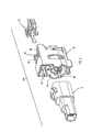
図1および図2に示すように、コネクタ位置保証装置10は、第1コネクタ部材12および第2コネクタ部材14とともに示されており、本発明のコネクタアセンブリ100を形成している。本発明のコネクタアセンブリ100について、以下に、より詳細に説明する。
An embodiment of a connector
As shown in FIGS. 1 and 2, the connector
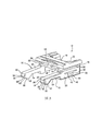
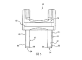
図3〜図6を参照して、コネクタ位置保証装置10は、1対の係止アーム部材16、交差部材18および1対の案内要素20を含んでいる。
1対の係止アーム部材16は、図3〜図5に最もよく示されているように、互いに離れて、ほぼ平行に配置されている。各係止アーム部材16は、頂面22、底面24、頂面22と底面24との間に延びる外向き側面26、後端部28および前端部30を有している。前端部30は、後端部28に一体的に接続され、後端部28の反対側に配置されている。各前端部30は、底面24から懸垂する係止突起32を有している。
3 to 6, the connector
The pair of
交差部材18は、後端部28の各頂面22において、1対の係止アーム部材16に一体的に接続されている。
各案内要素20は、後端部28の各外向き側面26に一体的に接続されており、後端部28の各外向き側面26から外側に向かって突出している。
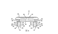
図3、図5および図6に最もよく示されているように、各前端部30は、頂面22と係止突起32との間に延びるほぼ平坦な正面34を有している。さらに、各係止アーム部材16は、頂面22とほぼ平坦な正面34とを相互接続する頂部曲縁36を含んでいる。また、各係止アーム部材16は、係止突起32と正面34とを相互接続する底部曲縁38を含んでいる。
The
Each
As best shown in FIGS. 3, 5 and 6, each
図3および図6に最もよく示されているように、各係止突起32は台形形状とされている。各係止突起32は、底部曲縁38に接続して底部曲縁38から後端部28に向かって、下方向および後方向に先細りになる第1先細り面40を有している。各係止突起32はまた、頂面22とほぼ平行に延びる、平坦な底部係止突起面42を有している。さらに、各係止突起32は、平坦な底部係止突起面42に接続して平坦な底部係止突起面42から係止アーム部材16の底面24に向かって上方向および後方向に先細りになる第2先細り面44を有している。
As best shown in FIGS. 3 and 6, each
図3および図6に示すように、各前端部30は、各後端部28と、片持ち状に一体形成されている。
図3、図4および図6に示すように、各案内要素20は、案内要素平坦面46、第1案内要素先細り面48および第2案内要素先細り面50を有している。各第1案内要素先細り面48は、案内要素平坦面46から後端部28の外向き側面26に向かって、前方向に先細りになっており、各第2案内要素先細り面50は、案内要素平坦面46から後端部28の外向き側面26に向かって、後方向に先細りになっている。
As shown in FIGS. 3 and 6, each
As shown in FIGS. 3, 4 and 6, each
図3〜図6を参照して、交差部材18は、頂部パネル52および1対の側部パネル54を有している。側部パネル54は、それぞれ、頂部パネル52と係止アーム部材16の後端部28の頂面22との間に配置され、頂部パネル52および前記頂面22に一体的に接続されて、1対の交差部材案内溝55を規定している。各交差部材案内溝55は、1対の係止アーム部材16と平行に延びている。さらに、交差部材18は、頂部パネル52から離れて1対の側部パネル54の間に配置され頂部パネル52と平行に延びる底部パネル56を含んでいる。底部パネル56は、1対の側部パネル54の間で、1対の側部パネル54に一体的に接続されている。
With reference to FIGS. 3-6, the
さらに、交差部材18は、頂部パネル52と底部パネル56との間に配置されて頂部パネル52および底部パネル56を一体的に接続するリブ58を含んでいる。リブ58は、図4に示すように、1対の側部パネル54の間の略中央に配置されており、1対の係止アーム部材16と平行に延びている。
また、図3および図4に示すように、頂部パネル52は、係止アーム部材16の後端部28のそれぞれを越えて外側に延びており、1対の案内要素20のそれぞれを越えて外側に延びている。
Further, the
Also, as shown in FIGS. 3 and 4, the
本発明のコネクタアセンブリ100について、図1、図2および図7〜図16を参照して、以下に説明する。図1、図2および図7において、第1コネクタ部材12は、第1コネクタ空洞60を区画しており、ラッチ構造部62および第1コネクタターミナルハウジング64を含んでいる。これらは両方とも、第1コネクタ空洞60の中に配置され、第1コネクタ部材12に接続されている。
The
図7および図8に最もよく示されているように、ラッチ構造部62は、ラッチ66および1対の停止部67を含んでいる。各停止部67は、図7に最もよく示されているように、ラッチ66に接続されて、ラッチ66から横方向に延びている。
ラッチ66は、(実線で示す)通常緩和状態および(点線で仮想的に示す)偏移状態を有し、通常緩和状態と偏移状態との間で、可動とされている。ラッチ66は、通常緩和状態へと弾性的に付勢されている。
As best shown in FIGS. 7 and 8, the
The
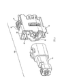
図7および図9に示すように、第2コネクタ部材14は、第1コネクタ空洞60に受けられる寸法とされており、第2コネクタ空洞68を区画している。第2コネクタ空洞68は、図11〜図14に最もよく示されており、以下に説明するように、第1コネクタターミナルハウジング64を受ける寸法とされている。第2コネクタ部材14は、図7および図10に最もよく示されているように、第2コネクタターミナルハウジング70を有している。第2コネクタターミナルハウジング70は、第2コネクタ空洞68の中に配置されており、第2コネクタ部材14に接続されている。
As shown in FIGS. 7 and 9, the
図10に最もよく示されているように、第2コネクタ部材14は、1対の捕捉部72と、1対の捕捉部72の間に配置された係止傾斜部74とを備える第2コネクタ外面14aを有している。第1コネクタ部材12および第2コネクタ部材14が、以下に、より詳細に説明するように、互いに接続されるべきときに、係止傾斜部74は、係止傾斜部面74aとして図1、図2および図7に示すように、第1コネクタ空洞60にほぼ対向する。1対の捕捉部72および係止傾斜部74は、第2コネクタ外面14aから突出している。
As best shown in FIG. 10, the
図2および図9を参照して、コネクタ位置保証装置10は、解除位置(図2および図11〜図14を参照)から係合位置(図16を参照)への移動のために、第1コネクタ部材12に摺動可能に接続されている。
図7を参照して、各係止アーム部材16の前端部30は、後端部に対して、上方向および下方向に移動することができる。各前端部30は、以下に、より詳細に説明するように、(実線で示す)通常緩和状態NRC、(仮想線で示す)中間偏移状態IFC、および(仮想線で示す)進行偏移状態EFCへ、ならびに、通常緩和状態と中間偏移状態と進行偏移状態との間で、連続的に(progressively)作動することができる。前端部30は、通常緩和状態NRCへと弾性的に付勢されている。
2 and 9, the connector
Referring to FIG. 7, the
図7に最もよく示されているように、ラッチ構造部62は、第1コネクタターミナルハウジング64に回動可能に取り付けられている。ラッチ構造部62は、支点部76を含んでおり、ラッチ66は、支点部にシーソー式に取り付けられている。また、図8に最もよく示されているように、ラッチ66は、第1および第2コネクタ部材が互いに接続されたときに係止傾斜部74を受ける寸法とされている係止傾斜部受け穴78を有している。
As best shown in FIG. 7, the
図8を参照して、第1コネクタ部材12は、第1コネクタ空洞60を形成する第1コネクタ内面12aを有している。第1コネクタ部材12は、第1コネクタ内面12a に形成された1対の案内受け溝80を含んでいる。1対の案内受け溝80は、互いに対向して、ラッチ構造部62に隣接するように配置されている。1対の案内受け溝80は、コネクタ位置保証装置10が第1コネクタ部材12に対して摺動することができるように、それぞれ、案内要素20が摺動するように構成されている。
Referring to FIG. 8, the
さらに、図1および図2に示すように、第1コネクタ部材12は、第1コネクタ内面12a に形成された案内レール溝を含んでいる。図1、図2および図9に示すように、第2コネクタ部材14は、第1コネクタ部材12の案内レール溝82に摺動可能に受けられる寸法とされた案内レール84を含んでいる。また、図1、図2および図8に最もよく示されているように、第1コネクタ部材12は、ラッチ構造部62の上方に配置された1対の第1コネクタ案内レール86を含んでいる。1対の第1コネクタ案内レール86は、上述したようにコネクタ位置保証装置10に形成された交差部材案内溝55を、それぞれ、摺動可能に受ける寸法とされている。
Further, as shown in FIGS. 1 and 2, the
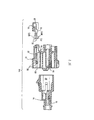
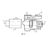
コネクタアセンブリ100の動作について、主に図11〜図16を参照しながら、以下に説明する。
コネクタ位置保証装置10が解除位置にあり、ラッチ66が通常緩和状態にある状態で、図11および図12に示すように第1および第2コネクタ部材を互いに完全に接続する前に、ラッチ66は、図8に最もよく示されているように、移動が禁止される。この移動禁止状態において、ラッチ66は、1対の停止部67のそれぞれと係止アーム部材16の前端部30とが、図8に示すように、少なくとも部分的に対向する。この結果として、第1コネクタ部材12に対するコネクタ位置保証装置10の摺動移動を防止している。
The operation of the
Prior to fully connecting the first and second connector members to each other as shown in FIGS. 11 and 12, with the connector
第1コネクタ部材12を(図11〜図14に示す)解除位置から係合位置(図16)へと動かす前に、第1コネクタ部材12および第2コネクタ部材14を、図11〜図13の矢印Aおよび矢印Bで示すように互いに向かって移動させることにより、接続する。当業者であれば、第1コネクタ部材12および第2コネクタ部材14が、互いに、図12に示す第1挿入位置、図13に示す第2挿入位置および図14に示す第3挿入位置から、段階的に接続されることを理解するであろう。
Prior to moving the
図12に示す第1挿入位置において、第2コネクタ空洞68が第1コネクタターミナルハウジング64を受けながら、第1コネクタ空洞60は第2コネクタ部材を受け、コネクタ位置保証装置10が解除位置にある状態で、係止アーム部材16の前端部30が通常緩和状態に位置しつつ、係止傾斜部74はラッチ66に接触する。
図12および図13を参照して、第1コネクタ部材12および第2コネクタ部材14が、第1挿入位置から第2挿入位置へ移動すると、係止傾斜部74は、ラッチ66を、通常緩和状態(図12)から中間偏移状態(図13)へ、上方向に移動させて、係止アーム部材16の前端部30が通常緩和状態(図13)に留まりながら、コネクタ位置保証装置10の摺動運動を可能にするために、ラッチ66を移動禁止状態(図12)から解放する。
In the first insertion position shown in FIG. 12, the
Referring to FIGS. 12 and 13, when the
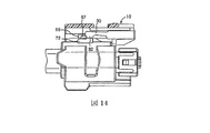
第1および第2コネクタ部材が、図13および図14に連続的に示すように、第2挿入位置(図13)から第3挿入位置(図14)へ移動すると、ラッチ66は、偏移状態(図13)から通常緩和状態(図14)へ、下方向に移動して、係止傾斜部74を係止傾斜部受け穴78の中に捕捉し、第1コネクタ部材12および第2コネクタ部材14をともに、主要係止状態(図14)に係止する。図14に示すように、各係止突起32および捕捉部72が互いに摺動可能に接触し、前端部30が通常緩和状態(図13)から中間偏移状態(図14)へ移動し、係止突起32が捕捉部72の頂部に配置されることに注意されたい。
When the first and second connector members move from the second insertion position (FIG. 13) to the third insertion position (FIG. 14) as shown in FIGS. 13 and 14, the
図14に示す第3挿入位置において、コネクタ位置保証装置10は、(例えば図14に示す)解除位置から(図16に示す)係合位置へ、摺動移動することが可能となる。各係止突起32が各停止部67の上へと摺動する(図14から図15)と、前端部30が中間偏移状態(図14)から進行偏移状態(図15)へ移動することに注意されたい。
コネクタ位置保証装置12が、図14〜図16に連続的に示すように、解除位置から係合位置へ移動すると、進行偏移状態(図15)にある前端部30は、摺動しながら停止部67を越えて移動する。コネクタ位置保証装置10が係合位置(図16)に到達したときに、前端部30は進行偏移状態(図15)から通常緩和状態(図16)へ移動し、係止突起32は、捕捉部72および停止部67の少なくとも実質的に前方に配置される。これで互いに完全に接続された(すなわち、主要係止状態および二次係止状態の両方で係止された)とみなされる第1コネクタ部材12および第2コネクタ部材14のために、主要係止状態とともに二次係止状態(図16)を提供する。
In the third insertion position shown in FIG. 14, the connector
When the connector
当業者であれば、コネクタ位置保証装置12が、第1および第2コネクタ部材との係合位置にあるときに、恒常的な負荷を受けておらず、実際には、通常緩和状態にあることを理解するであろう。また、コネクタ位置保証装置が係合位置にあるときに、ラッチ66の後部は、図16に最もよく示されているように、ユーザに対して露出している。ラッチ66は支点部76にシーソー式に取り付けられているため、ラッチは、コネクタ位置保証装置12を第1および第2コネクタ部材との係合から解放するために、ユーザが直接押し下げることができる。
If the person skilled in the art is in a position where the connector
しかし、本発明は、他のさまざまな異なる態様で実施されてもよく、本明細書に記載した例示的な実施形態に限定されると理解すべきではない。むしろ、これらの例示的な実施形態は、本開示を徹底的かつ完全にし、当業者に対して本発明の請求の範囲を十分に伝えるようにするために、提供されている。 However, it should be understood that the present invention may be implemented in a variety of other different ways and is not limited to the exemplary embodiments described herein. Rather, these exemplary embodiments are provided so that this disclosure will be thorough and complete, and will fully convey the scope of the claims to those skilled in the art.
Claims (31)
前記後端部における前記各頂面で、前記1対の係止アーム部材に一体的に接続された交差部材と、
1対の案内要素であって、それぞれが、前記後端部の前記外向き側面のそれぞれに一体的に接続されており、前記後端部の前記外向き側面のそれぞれから外側へ突出している1対の案内要素とを備える、コネクタ位置保証装置。 A pair of locking arm members disposed substantially parallel to and away from each other, the top surface, the bottom surface, an outward side surface extending between the top surface and the bottom surface, a rear end portion, and the rear end portion A pair of locking arm members having a front end portion integrally connected to the rear end portion and disposed on the opposite side of the rear end portion, each front end portion having a locking projection suspended from the bottom surface When,
A cross member integrally connected to the pair of locking arm members at each top surface at the rear end portion;
A pair of guide elements, each connected integrally to each of the outward side surfaces of the rear end portion, and projecting outward from each of the outward side surfaces of the rear end portion. A connector position assurance device comprising a pair of guide elements.
前記第1コネクタ空洞に受けられる寸法とされており、前記第1コネクタターミナルハウジングを受ける寸法とされた第2コネクタ空洞を区画しており、前記第2コネクタ空洞の中に配置され当該第2コネクタ部材に接続された第2コネクタターミナルハウジングを有しており、1対の捕捉部と、前記1対の捕捉部の間に配置された係止傾斜部とを備える第2コネクタ外面を有する第2コネクタ部材であって、前記1対の捕捉部および前記係止傾斜部は、前記第2コネクタ外面から突出しているものである、第2コネクタ部材と、
解除位置から係合位置への移動のために、前記第1コネクタ部材に摺動可能に接続されており、互いに離れてほぼ平行に配置された1対の係止アーム部材および前記1対の係止アーム部材に一体的に接続された交差部材を有するコネクタ位置保証装置であって、各係止アーム部材は、後端部、および前記後端部に一体的に接続され、前記後端部の反対側に配置された前端部を有し、各前端部は、当該前端部から懸垂する係止突起を有しており、前記前端部は、前記後端部に対して、上方向および下方向に移動することができ、通常緩和状態、中間偏移状態および進行偏移状態、ならびに、前記通常緩和状態と前記中間偏移状態と前記進行偏移状態との間で、連続的に移動することができ、前記前端部は、前記通常緩和状態へと弾性的に付勢されているものである、コネクタ位置保証装置と、
を備えるコネクタアセンブリであって、
前記第1および第2コネクタ部材を、前記コネクタ位置保証装置が前記解除状態にあり、前記ラッチが前記通常緩和状態にある状態で、互いに完全に接続する前に、移動ができない状態にある前記ラッチは、前記1対の停止部のそれぞれと前記前端部とが少なくとも部分的に対向している結果として、前記第1コネクタ部材に対する前記コネクタ位置保証装置の摺動移動を防止しており、
前記第1コネクタ部材を前記解除位置から前記係合位置へと動かす前に、前記第1および第2コネクタ部材が、第1挿入位置、第2挿入位置および第3挿入位置から段階的に、互いに向かって移動されることにより、接続され、
前記第1挿入位置において、前記第2コネクタ空洞が前記第1コネクタターミナルハウジングを受けながら、前記第1コネクタ空洞は前記第2コネクタ部材を受け、前記コネクタ位置保証装置が前記解除位置にある状態で、前記係止アーム部材の前記前端部が前記通常緩和状態に位置しつつ、前記係止傾斜部は前記ラッチに接触し、
前記第1および第2コネクタ部材が、前記第1挿入位置から前記第2挿入位置へ移動すると、前記係止傾斜部は、前記ラッチを、前記通常緩和状態から前記中間偏移状態へ、上方向に移動させて、前記係止アーム部材の前記前端部が前記通常緩和状態に留まりながら、前記コネクタ位置保証装置の摺動運動を可能にするために、前記ラッチを前記移動禁止状態から解放し、
前記第1および第2コネクタ部材が、前記第2挿入位置から前記第3挿入位置へ移動すると、前記ラッチは、前記偏移状態から前記通常緩和状態へ、下方向に移動して、前記係止傾斜部を捕捉し、前記第1および第2コネクタ部材をともに、主要係止状態に係止し、前記係止突起のそれぞれおよび前記捕捉部が互いに摺動可能に接触し、前記前端部が前記通常緩和状態から前記中間偏移状態へ移動し、前記係止突起が前記捕捉部の頂部に配置され、
前記第3挿入位置において、前記コネクタ位置保証装置は、前記係止突起が、それぞれ、前記停止部の上へと摺動すると、前記前端部が前記中間偏移状態から前記進行偏移状態へ移動するように、前記解除位置から前記係合位置へ、摺動移動することが可能であり、
前記コネクタ位置保証装置が前記解除位置から前記係合位置へ移動すると、前記進行偏移状態にある前記前端部は、摺動しながら前記停止部を越えて移動し、
前記コネクタ位置保証装置が前記係合位置に到達したときに、前記前端部は前記進行偏移状態から前記通常緩和状態へ移動し、前記係止突起は、前記捕捉部および前記停止部の少なくとも実質的に前方に配置され、互いに完全に接続されている前記第1および第2コネクタ部材のために、二次係止状態を提供する、コネクタアセンブリ。 A first connector member that forms a first connector cavity and includes a latch structure portion disposed in the first connector cavity and connected to the first connector member, and a first connector terminal housing, wherein the latch structure portion Includes a latch and a pair of stops, the latch being movable between a normal relaxed state and a shifted state, and between the normal relaxed state and the shifted state, wherein the latch is A first connector member that is normally elastically biased to a relaxed state, and each stop is connected to the latch and extends laterally from the latch;
The second connector cavity is dimensioned to be received by the first connector cavity and is dimensioned to receive the first connector terminal housing, and is disposed in the second connector cavity and the second connector A second connector terminal housing connected to the member, and having a second connector outer surface comprising a pair of capture portions and a locking inclined portion disposed between the pair of capture portions; A connector member, wherein the pair of capturing portions and the locking inclined portion protrude from the outer surface of the second connector, and a second connector member,
A pair of locking arm members slidably connected to the first connector member for movement from the release position to the engagement position and disposed substantially parallel to each other and the pair of engagement members A connector position assurance device having a cross member integrally connected to a stop arm member, wherein each locking arm member is integrally connected to a rear end portion and the rear end portion of the rear end portion. The front end portion is disposed on the opposite side, each front end portion has a locking projection suspended from the front end portion, and the front end portion is upward and downward with respect to the rear end portion. And continuously moving between the normal relaxation state, the intermediate shift state, and the forward shift state, and between the normal relax state, the intermediate shift state, and the forward shift state. The front end is elastically biased to the normal relaxed state. A shall, with the connector position assurance device,
A connector assembly comprising:
The first and second connector members in a state in which the connector position assurance device is in the released state, and the latch is in a state in which it cannot move before it is completely connected to each other in the normal relaxed state. Is preventing sliding movement of the connector position assurance device with respect to the first connector member as a result of at least partially facing each of the pair of stop portions and the front end portion,
Before moving the first connector member from the release position to the engagement position, the first and second connector members are stepped from the first insertion position, the second insertion position, and the third insertion position, step by step. Connected by moving towards
In the first insertion position, while the second connector cavity receives the first connector terminal housing, the first connector cavity receives the second connector member, and the connector position assurance device is in the release position. The front end portion of the locking arm member is positioned in the normal relaxed state, and the locking inclined portion contacts the latch,
When the first and second connector members move from the first insertion position to the second insertion position, the locking inclined portion moves the latch upward from the normal relaxed state to the intermediate shift state. In order to allow the connector position assurance device to slide while the front end of the locking arm member remains in the normal relaxed state, the latch is released from the movement prohibited state,
When the first and second connector members move from the second insertion position to the third insertion position, the latch moves downward from the deviation state to the normal relaxation state, and the locking The inclined portion is captured, the first and second connector members are both locked in a main locking state, the locking projections and the capturing portion are slidably in contact with each other, and the front end portion is the Move from the normal relaxed state to the intermediate shift state, the locking projection is disposed on the top of the capture portion,
In the third insertion position, the connector position assurance device moves the front end portion from the intermediate shift state to the advance shift state when the locking protrusions slide on the stop portions, respectively. So that it can slide from the release position to the engagement position,
When the connector position assurance device moves from the release position to the engagement position, the front end portion in the forward shift state moves beyond the stop portion while sliding,
When the connector position assurance device reaches the engagement position, the front end portion moves from the forward shift state to the normal relaxed state, and the locking projection is at least substantially the capture portion and the stop portion. A connector assembly that provides a secondary locking condition for the first and second connector members that are generally forwardly positioned and fully connected to each other.
Applications Claiming Priority (2)
| Application Number | Priority Date | Filing Date | Title |
|---|---|---|---|
| US11/634,213 US7326074B1 (en) | 2006-12-06 | 2006-12-06 | Connector position assurance device and a connector assembly incorporating the connector position assurance device |
| PCT/US2007/021961 WO2008069866A2 (en) | 2006-12-06 | 2007-10-15 | Connector position assurance device and a connector assembly incorporating the connector position assurance device |
Publications (2)
| Publication Number | Publication Date |
|---|---|
| JP2010511993A true JP2010511993A (en) | 2010-04-15 |
| JP2010511993A5 JP2010511993A5 (en) | 2010-08-05 |
Family
ID=38988772
Family Applications (1)
| Application Number | Title | Priority Date | Filing Date |
|---|---|---|---|
| JP2009540226A Pending JP2010511993A (en) | 2006-12-06 | 2007-10-15 | Connector position assurance device and connector assembly incorporating the same |
Country Status (6)
| Country | Link |
|---|---|
| US (1) | US7326074B1 (en) |
| EP (1) | EP2089938A2 (en) |
| JP (1) | JP2010511993A (en) |
| KR (1) | KR20090092276A (en) |
| CN (1) | CN101563817A (en) |
| WO (1) | WO2008069866A2 (en) |
Families Citing this family (63)
| Publication number | Priority date | Publication date | Assignee | Title |
|---|---|---|---|---|
| US7601019B2 (en) * | 2007-06-22 | 2009-10-13 | Delphi Technologies, Inc. | Electrical connection system |
| US7470138B1 (en) * | 2007-07-18 | 2008-12-30 | J.S.T. Corporation | Connector position assurance device and connector assembly apparatus incorporating the same |
| TWI359538B (en) * | 2008-07-01 | 2012-03-01 | Delta Electronics Inc | Electrical connector with latching device |
| US7682181B1 (en) * | 2008-09-09 | 2010-03-23 | Tyco Electronics Corporation | Latch securing member |
| US7892012B1 (en) * | 2009-08-24 | 2011-02-22 | Archtech Electronics Corporation | Connector locking device |
| EP2302744B1 (en) * | 2009-09-24 | 2012-06-20 | Tyco Electronics France SAS | Electrical socket with supporting element, electrical plug with deformation pocket and plug assembly with at least one socket and one plug as well as a method for connecting a plug and a socket |
| KR101117968B1 (en) * | 2009-11-05 | 2012-02-16 | 주식회사 경신 | Locking device |
| US8287306B2 (en) * | 2010-06-30 | 2012-10-16 | Delphi Technologies, Inc. | Electrical connection system that absorbs multi-connector positional mating tolerance variation |
| US8016606B1 (en) * | 2011-01-10 | 2011-09-13 | J.S.T. Corporation | Unstressed connector position assurance device and connector assembly |
| JP5728245B2 (en) * | 2011-02-21 | 2015-06-03 | 矢崎総業株式会社 | connector |
| US8277243B1 (en) * | 2011-03-25 | 2012-10-02 | Delphi Technologies, Inc. | Connector position assurance device |
| US8323046B1 (en) * | 2011-05-23 | 2012-12-04 | Delphi Technologies, Inc. | Bi-directional CPA member to prevent unmating of multiple connectors |
| US8678846B2 (en) * | 2012-03-28 | 2014-03-25 | Tyco Electronics Corporation | Electrical connector with connector position assurance device |
| US8926355B2 (en) * | 2012-06-29 | 2015-01-06 | Lear Corporation | Connector position assurance device for a connector assembly |
| DE102013205447B4 (en) * | 2013-03-27 | 2022-06-09 | Lisa Dräxlmaier GmbH | Electrical connector and electrical connector with such a connector |
| US9515410B2 (en) * | 2013-05-08 | 2016-12-06 | Sumitomo Wiring Systems, Ltd. | Connector with a slider releasably locked to a housing by a resilient stopper having two points of support for resilient deflection |
| EP2996208A4 (en) * | 2013-05-08 | 2016-04-20 | Sumitomo Wiring Systems | Connector |
| CN105284016B (en) * | 2013-06-07 | 2020-01-03 | 安费诺富加宜(亚洲)私人有限公司 | Connector assembly |
| USD745459S1 (en) * | 2013-06-17 | 2015-12-15 | Wago Verwaltungsgesellschaft Mbh | Electrical plug-in connector |
| JP6008250B2 (en) * | 2013-08-05 | 2016-10-19 | 住友電装株式会社 | connector |
| US9356394B2 (en) | 2013-12-11 | 2016-05-31 | JAE Oregon, Inc. | Self-rejecting connector |
| US8968021B1 (en) | 2013-12-11 | 2015-03-03 | JAE Oregon, Inc. | Self-rejecting automotive harness connector |
| US9054458B1 (en) | 2014-02-10 | 2015-06-09 | Yazaki North America, Inc. | Connector position assurance |
| WO2015160747A2 (en) * | 2014-04-14 | 2015-10-22 | Fci Asia Pte. Ltd | Crimp-to-wire electrical connector assembly |
| JP2016009597A (en) * | 2014-06-24 | 2016-01-18 | 日本航空電子工業株式会社 | connector |
| DE102015201089A1 (en) | 2015-01-22 | 2016-07-28 | Te Connectivity Germany Gmbh | Intermediate housing with a CPA receptacle and connector systems comprising such |
| EP3089280A1 (en) * | 2015-04-29 | 2016-11-02 | Delphi International Operations Luxembourg S.à r.l. | Electrical connector system comprising a secondary locking device |
| US9705228B2 (en) * | 2015-08-20 | 2017-07-11 | Delphi Technologies, Inc. | Connector system with disconnection evident connector position assurance feature |
| US10673168B2 (en) * | 2016-01-14 | 2020-06-02 | J.S.T. Corporation | MSL connector series |
| CN105591236A (en) * | 2016-02-22 | 2016-05-18 | 昆山全方位电子科技有限公司 | Lock catch element and electric connector provided with lock catch element |
| JP6288125B2 (en) * | 2016-03-03 | 2018-03-07 | 第一精工株式会社 | connector |
| FR3049118A1 (en) * | 2016-03-15 | 2017-09-22 | Tyco Electronics France Sas | CONNECTOR POSITION ASSURANCE DEVICE, CONNECTOR HOUSING, AND ELECTRICAL CONNECTOR SYSTEM |
| US10038278B2 (en) | 2016-03-17 | 2018-07-31 | Te Connectivity Corporation | Electrical connector having a connector position assurance element |
| FR3051080B1 (en) * | 2016-05-09 | 2022-07-22 | Delphi Int Operations Luxembourg Sarl | CONNECTION ASSEMBLY AND METHOD OF ASSEMBLING THIS CONNECTION ASSEMBLY |
| EP3252880B1 (en) * | 2016-06-02 | 2020-05-20 | Aptiv Technologies Limited | Electrical connector assembly with improved locking device |
| US9640895B1 (en) * | 2016-06-14 | 2017-05-02 | Te Connectivity Corporation | Electrical connector having a TPA |
| JP1584769S (en) | 2016-12-13 | 2017-08-28 | ||
| JP1584768S (en) | 2016-12-13 | 2017-08-28 | ||
| US10855025B2 (en) | 2017-05-01 | 2020-12-01 | J.S.T. Corporation | Connector position assurance device, connector system and method for operating the connector system |
| US10454209B2 (en) | 2017-05-01 | 2019-10-22 | J.S.T. Corporation | Connector position assurance device, a connector apparatus having male and female connector assemblies with connector position assurance device, a male connector assembly, a female connector assembly, and a method for assembling the connector apparatus |
| DE102017004887B4 (en) * | 2017-05-20 | 2023-05-04 | Kostal Kontakt Systeme Gmbh | Connector part and connector assembly |
| US9929509B1 (en) | 2017-06-12 | 2018-03-27 | Delphi Technologies, Inc. | Connector system with low profile connector position assurance device |
| USD831579S1 (en) | 2017-06-14 | 2018-10-23 | Delphi Technologies, Inc. | Connector position assurance device |
| US10038269B1 (en) * | 2017-06-29 | 2018-07-31 | Cisco Technology, Inc. | Self-locking electrical cable retainer |
| US10109950B1 (en) * | 2017-09-13 | 2018-10-23 | Delphi Technologies, Inc. | High vibration connector with a connector-position-assurance device |
| DE102017123696A1 (en) * | 2017-10-11 | 2019-04-11 | Amphenol-Tuchel Electronics Gmbh | High-current connector comprising a plug-in element and a socket element and a locking device |
| US10355414B1 (en) | 2018-02-08 | 2019-07-16 | Delphi Technologies, Llc | Connector with a connector position assurance device |
| EP3766139B1 (en) | 2018-03-12 | 2023-12-27 | J.S.T. Corporation | Electric connector with cpa |
| US11183804B2 (en) | 2018-07-23 | 2021-11-23 | J.S.T. Corporation | Connector system and electrical circuit for connector position assurance member |
| JP6800921B2 (en) | 2018-08-01 | 2020-12-16 | 矢崎総業株式会社 | connector |
| JP6839145B2 (en) * | 2018-09-03 | 2021-03-03 | 矢崎総業株式会社 | connector |
| JP6865725B2 (en) * | 2018-10-31 | 2021-04-28 | 矢崎総業株式会社 | connector |
| FR3088490B1 (en) * | 2018-11-12 | 2023-12-08 | Raydiall | CONNECTOR HOUSING EQUIPPED WITH AN IMPROVED CONNECTOR POSITION ASSURANCE (CPA) DEVICE |
| KR102647188B1 (en) * | 2018-11-14 | 2024-03-13 | 현대자동차주식회사 | Connector device |
| CN109546406B (en) * | 2018-11-29 | 2020-05-05 | 安徽江淮汽车集团股份有限公司 | Automobile wire harness plug-in |
| US10566726B1 (en) | 2018-11-29 | 2020-02-18 | Lear Corporation | Connector with sliding terminal position assurance |
| US11251560B2 (en) * | 2019-03-11 | 2022-02-15 | TE Connectivity Services Gmbh | Terminal position assurance member with multiple latches |
| JP2021005447A (en) * | 2019-06-25 | 2021-01-14 | 住友電装株式会社 | Connector, fitting position assurance member, and wiring harness |
| JP7132201B2 (en) * | 2019-10-17 | 2022-09-06 | 矢崎総業株式会社 | connector |
| CN113224570B (en) * | 2020-01-20 | 2023-11-28 | 泰科电子(上海)有限公司 | Connector assembly with position assurance device |
| JP2022090961A (en) | 2020-12-08 | 2022-06-20 | 日本航空電子工業株式会社 | Connector assembly |
| JP1703880S (en) * | 2021-04-02 | 2022-01-04 | ||
| US11710927B2 (en) * | 2021-06-01 | 2023-07-25 | Lear Corporation | Electrical connector with connector position assurance and mechanical assist |
Citations (8)
| Publication number | Priority date | Publication date | Assignee | Title |
|---|---|---|---|---|
| JPH01165582U (en) * | 1988-05-13 | 1989-11-20 | ||
| JPH10223312A (en) * | 1997-02-03 | 1998-08-21 | Yazaki Corp | Connector device |
| JP2002056933A (en) * | 2000-08-10 | 2002-02-22 | Sumitomo Wiring Syst Ltd | Connector |
| JP2002170628A (en) * | 2000-09-22 | 2002-06-14 | Yazaki Corp | Connector locking guarantee method, connector and connector housing with locking guarantee mechanism |
| JP2004095439A (en) * | 2002-09-02 | 2004-03-25 | Sumitomo Wiring Syst Ltd | Connector with detection member |
| JP2004164940A (en) * | 2002-11-12 | 2004-06-10 | Sumitomo Wiring Syst Ltd | Connector |
| JP2006221921A (en) * | 2005-02-09 | 2006-08-24 | Sumitomo Wiring Syst Ltd | Connector |
| JP2006244975A (en) * | 2005-02-04 | 2006-09-14 | Sumitomo Wiring Syst Ltd | Connector |
Family Cites Families (18)
| Publication number | Priority date | Publication date | Assignee | Title |
|---|---|---|---|---|
| JP2537302B2 (en) | 1990-03-01 | 1996-09-25 | 矢崎総業株式会社 | Lock check device for electrical connector |
| US6068507A (en) * | 1996-11-04 | 2000-05-30 | Molex Incorporated | Housing adapted to an electrical connector position assurance system |
| US6345855B2 (en) | 1996-11-27 | 2002-02-12 | Hwh Corporation | Level floor room extension |
| US5775930A (en) | 1996-12-13 | 1998-07-07 | General Motors Corporation | Electrical connector with locking connector position assurance member |
| US6077101A (en) | 1997-11-18 | 2000-06-20 | General Motors Corporation | Electronic connector with CPA device |
| DE19832352A1 (en) * | 1998-07-20 | 2000-01-27 | Walter Holzer | Touch-safe base / socket system for lights |
| US6045388A (en) * | 1998-09-02 | 2000-04-04 | Molex Incorporated | Electrical connector position assurance system |
| US6234826B1 (en) * | 1999-04-30 | 2001-05-22 | Cardell Corporation | Connector position assurance device |
| US6261116B1 (en) | 1999-11-22 | 2001-07-17 | Yazaki North America, Inc. | Connector position assurance element with lock protection feature |
| US6533601B2 (en) * | 2001-02-09 | 2003-03-18 | Tyco Electronics Corporation | Electrical connector assembly with a laterally deflectable latch member and CPA |
| US6435895B1 (en) * | 2001-04-27 | 2002-08-20 | Delphi Technologies, Inc. | Connector position assurance device |
| US6491542B1 (en) | 2002-01-16 | 2002-12-10 | Yazaki North America | Combined connection and terminal position assurance structure for vehicle wiring connectors |
| US6716052B2 (en) * | 2002-02-21 | 2004-04-06 | Tyco Electronics Corporation | Connector position assurance device and latch |
| JP2003249308A (en) * | 2002-02-25 | 2003-09-05 | Tyco Electronics Amp Kk | Electrical connector assembly |
| US6780045B2 (en) * | 2002-03-06 | 2004-08-24 | Tyco Electronics Corporation | Connector position assurance device |
| US6893277B2 (en) * | 2003-02-26 | 2005-05-17 | Tyco Electronics Corporation | Squib connector assembly with CPA |
| US6811424B2 (en) * | 2003-03-26 | 2004-11-02 | Fci Americas Technology, Inc. | Electrical connector having connector position assurance member |
| US7175451B2 (en) * | 2005-03-15 | 2007-02-13 | Tyco Electronics Corporation | Lever mated connector assembly with a position assurance device |
-
2006
- 2006-12-06 US US11/634,213 patent/US7326074B1/en active Active
-
2007
- 2007-10-15 JP JP2009540226A patent/JP2010511993A/en active Pending
- 2007-10-15 EP EP07839553A patent/EP2089938A2/en not_active Withdrawn
- 2007-10-15 WO PCT/US2007/021961 patent/WO2008069866A2/en active Application Filing
- 2007-10-15 KR KR1020097011674A patent/KR20090092276A/en not_active Application Discontinuation
- 2007-10-15 CN CNA2007800451555A patent/CN101563817A/en active Pending
Patent Citations (8)
| Publication number | Priority date | Publication date | Assignee | Title |
|---|---|---|---|---|
| JPH01165582U (en) * | 1988-05-13 | 1989-11-20 | ||
| JPH10223312A (en) * | 1997-02-03 | 1998-08-21 | Yazaki Corp | Connector device |
| JP2002056933A (en) * | 2000-08-10 | 2002-02-22 | Sumitomo Wiring Syst Ltd | Connector |
| JP2002170628A (en) * | 2000-09-22 | 2002-06-14 | Yazaki Corp | Connector locking guarantee method, connector and connector housing with locking guarantee mechanism |
| JP2004095439A (en) * | 2002-09-02 | 2004-03-25 | Sumitomo Wiring Syst Ltd | Connector with detection member |
| JP2004164940A (en) * | 2002-11-12 | 2004-06-10 | Sumitomo Wiring Syst Ltd | Connector |
| JP2006244975A (en) * | 2005-02-04 | 2006-09-14 | Sumitomo Wiring Syst Ltd | Connector |
| JP2006221921A (en) * | 2005-02-09 | 2006-08-24 | Sumitomo Wiring Syst Ltd | Connector |
Also Published As
| Publication number | Publication date |
|---|---|
| WO2008069866A2 (en) | 2008-06-12 |
| US7326074B1 (en) | 2008-02-05 |
| EP2089938A2 (en) | 2009-08-19 |
| CN101563817A (en) | 2009-10-21 |
| KR20090092276A (en) | 2009-08-31 |
| WO2008069866A3 (en) | 2008-07-24 |
Similar Documents
| Publication | Publication Date | Title |
|---|---|---|
| JP2010511993A (en) | Connector position assurance device and connector assembly incorporating the same | |
| JP2010511993A5 (en) | ||
| JP5751196B2 (en) | connector | |
| US7828579B2 (en) | Latch locking type connector | |
| JP5185345B2 (en) | Electrical connector having connector position assurance member | |
| JP4664436B2 (en) | Connector position assurance device and connector assembly incorporating the same | |
| JP5810980B2 (en) | connector | |
| KR101797866B1 (en) | Connector | |
| US5711684A (en) | Connector housing locking mechanism | |
| JP5768802B2 (en) | connector | |
| JP3810285B2 (en) | Half-mating prevention connector | |
| JP2014170746A (en) | Connector assembly equipped with connector position assurance stabilization device | |
| WO2011077685A1 (en) | Locking cover for electrical connection appliance | |
| JP2004103551A (en) | Connector | |
| US6811437B2 (en) | Connector and method of mounting it | |
| JP2019079638A (en) | Connector and connector assembly | |
| JP2009043648A (en) | Connector | |
| JP4496475B2 (en) | connector | |
| JPWO2019131372A1 (en) | connector | |
| JP2020080271A (en) | connector | |
| JP2017121833A (en) | Seat slide device | |
| JP4924902B2 (en) | Lock structure and connector | |
| JP2005197167A (en) | Connector | |
| JP2004200147A (en) | Male connector equipped with locking element | |
| KR20090001328A (en) | Connector assembly |
Legal Events
| Date | Code | Title | Description |
|---|---|---|---|
| A521 | Written amendment |
Free format text: JAPANESE INTERMEDIATE CODE: A523 Effective date: 20100615 |
|
| A621 | Written request for application examination |
Free format text: JAPANESE INTERMEDIATE CODE: A621 Effective date: 20100617 |
|
| A871 | Explanation of circumstances concerning accelerated examination |
Free format text: JAPANESE INTERMEDIATE CODE: A871 Effective date: 20100617 |
|
| RD04 | Notification of resignation of power of attorney |
Free format text: JAPANESE INTERMEDIATE CODE: A7424 Effective date: 20100621 |
|
| A975 | Report on accelerated examination |
Free format text: JAPANESE INTERMEDIATE CODE: A971005 Effective date: 20100707 |
|
| A131 | Notification of reasons for refusal |
Free format text: JAPANESE INTERMEDIATE CODE: A131 Effective date: 20100715 |
|
| A02 | Decision of refusal |
Free format text: JAPANESE INTERMEDIATE CODE: A02 Effective date: 20101209 |