JP2010502432A - Integrated microchannel synthesis and separation - Google Patents
Integrated microchannel synthesis and separation Download PDFInfo
- Publication number
- JP2010502432A JP2010502432A JP2009527391A JP2009527391A JP2010502432A JP 2010502432 A JP2010502432 A JP 2010502432A JP 2009527391 A JP2009527391 A JP 2009527391A JP 2009527391 A JP2009527391 A JP 2009527391A JP 2010502432 A JP2010502432 A JP 2010502432A
- Authority
- JP
- Japan
- Prior art keywords
- microchannel
- microchannels
- microchannel reactor
- reactor
- series
- Prior art date
- Legal status (The legal status is an assumption and is not a legal conclusion. Google has not performed a legal analysis and makes no representation as to the accuracy of the status listed.)
- Pending
Links
Images


Classifications
-
- B—PERFORMING OPERATIONS; TRANSPORTING
- B01—PHYSICAL OR CHEMICAL PROCESSES OR APPARATUS IN GENERAL
- B01J—CHEMICAL OR PHYSICAL PROCESSES, e.g. CATALYSIS OR COLLOID CHEMISTRY; THEIR RELEVANT APPARATUS
- B01J19/00—Chemical, physical or physico-chemical processes in general; Their relevant apparatus
- B01J19/0093—Microreactors, e.g. miniaturised or microfabricated reactors
-
- C—CHEMISTRY; METALLURGY
- C07—ORGANIC CHEMISTRY
- C07C—ACYCLIC OR CARBOCYCLIC COMPOUNDS
- C07C1/00—Preparation of hydrocarbons from one or more compounds, none of them being a hydrocarbon
- C07C1/02—Preparation of hydrocarbons from one or more compounds, none of them being a hydrocarbon from oxides of a carbon
- C07C1/04—Preparation of hydrocarbons from one or more compounds, none of them being a hydrocarbon from oxides of a carbon from carbon monoxide with hydrogen
- C07C1/0405—Apparatus
- C07C1/041—Reactors
-
- C—CHEMISTRY; METALLURGY
- C07—ORGANIC CHEMISTRY
- C07C—ACYCLIC OR CARBOCYCLIC COMPOUNDS
- C07C1/00—Preparation of hydrocarbons from one or more compounds, none of them being a hydrocarbon
- C07C1/02—Preparation of hydrocarbons from one or more compounds, none of them being a hydrocarbon from oxides of a carbon
- C07C1/04—Preparation of hydrocarbons from one or more compounds, none of them being a hydrocarbon from oxides of a carbon from carbon monoxide with hydrogen
- C07C1/0405—Apparatus
- C07C1/042—Temperature controlling devices; Heat exchangers
-
- C—CHEMISTRY; METALLURGY
- C07—ORGANIC CHEMISTRY
- C07C—ACYCLIC OR CARBOCYCLIC COMPOUNDS
- C07C1/00—Preparation of hydrocarbons from one or more compounds, none of them being a hydrocarbon
- C07C1/02—Preparation of hydrocarbons from one or more compounds, none of them being a hydrocarbon from oxides of a carbon
- C07C1/04—Preparation of hydrocarbons from one or more compounds, none of them being a hydrocarbon from oxides of a carbon from carbon monoxide with hydrogen
- C07C1/0425—Catalysts; their physical properties
-
- C—CHEMISTRY; METALLURGY
- C07—ORGANIC CHEMISTRY
- C07C—ACYCLIC OR CARBOCYCLIC COMPOUNDS
- C07C1/00—Preparation of hydrocarbons from one or more compounds, none of them being a hydrocarbon
- C07C1/02—Preparation of hydrocarbons from one or more compounds, none of them being a hydrocarbon from oxides of a carbon
- C07C1/04—Preparation of hydrocarbons from one or more compounds, none of them being a hydrocarbon from oxides of a carbon from carbon monoxide with hydrogen
- C07C1/0455—Reaction conditions
- C07C1/048—Temperature controlling measures
-
- C—CHEMISTRY; METALLURGY
- C07—ORGANIC CHEMISTRY
- C07C—ACYCLIC OR CARBOCYCLIC COMPOUNDS
- C07C29/00—Preparation of compounds having hydroxy or O-metal groups bound to a carbon atom not belonging to a six-membered aromatic ring
- C07C29/15—Preparation of compounds having hydroxy or O-metal groups bound to a carbon atom not belonging to a six-membered aromatic ring by reduction of oxides of carbon exclusively
- C07C29/151—Preparation of compounds having hydroxy or O-metal groups bound to a carbon atom not belonging to a six-membered aromatic ring by reduction of oxides of carbon exclusively with hydrogen or hydrogen-containing gases
- C07C29/152—Preparation of compounds having hydroxy or O-metal groups bound to a carbon atom not belonging to a six-membered aromatic ring by reduction of oxides of carbon exclusively with hydrogen or hydrogen-containing gases characterised by the reactor used
-
- C—CHEMISTRY; METALLURGY
- C10—PETROLEUM, GAS OR COKE INDUSTRIES; TECHNICAL GASES CONTAINING CARBON MONOXIDE; FUELS; LUBRICANTS; PEAT
- C10G—CRACKING HYDROCARBON OILS; PRODUCTION OF LIQUID HYDROCARBON MIXTURES, e.g. BY DESTRUCTIVE HYDROGENATION, OLIGOMERISATION, POLYMERISATION; RECOVERY OF HYDROCARBON OILS FROM OIL-SHALE, OIL-SAND, OR GASES; REFINING MIXTURES MAINLY CONSISTING OF HYDROCARBONS; REFORMING OF NAPHTHA; MINERAL WAXES
- C10G2/00—Production of liquid hydrocarbon mixtures of undefined composition from oxides of carbon
- C10G2/30—Production of liquid hydrocarbon mixtures of undefined composition from oxides of carbon from carbon monoxide with hydrogen
- C10G2/32—Production of liquid hydrocarbon mixtures of undefined composition from oxides of carbon from carbon monoxide with hydrogen with the use of catalysts
- C10G2/34—Apparatus, reactors
- C10G2/341—Apparatus, reactors with stationary catalyst bed
-
- B—PERFORMING OPERATIONS; TRANSPORTING
- B01—PHYSICAL OR CHEMICAL PROCESSES OR APPARATUS IN GENERAL
- B01J—CHEMICAL OR PHYSICAL PROCESSES, e.g. CATALYSIS OR COLLOID CHEMISTRY; THEIR RELEVANT APPARATUS
- B01J2219/00—Chemical, physical or physico-chemical processes in general; Their relevant apparatus
- B01J2219/00781—Aspects relating to microreactors
- B01J2219/00783—Laminate assemblies, i.e. the reactor comprising a stack of plates
-
- B—PERFORMING OPERATIONS; TRANSPORTING
- B01—PHYSICAL OR CHEMICAL PROCESSES OR APPARATUS IN GENERAL
- B01J—CHEMICAL OR PHYSICAL PROCESSES, e.g. CATALYSIS OR COLLOID CHEMISTRY; THEIR RELEVANT APPARATUS
- B01J2219/00—Chemical, physical or physico-chemical processes in general; Their relevant apparatus
- B01J2219/00781—Aspects relating to microreactors
- B01J2219/00819—Materials of construction
- B01J2219/00822—Metal
-
- B—PERFORMING OPERATIONS; TRANSPORTING
- B01—PHYSICAL OR CHEMICAL PROCESSES OR APPARATUS IN GENERAL
- B01J—CHEMICAL OR PHYSICAL PROCESSES, e.g. CATALYSIS OR COLLOID CHEMISTRY; THEIR RELEVANT APPARATUS
- B01J2219/00—Chemical, physical or physico-chemical processes in general; Their relevant apparatus
- B01J2219/00781—Aspects relating to microreactors
- B01J2219/00819—Materials of construction
- B01J2219/00835—Comprising catalytically active material
-
- B—PERFORMING OPERATIONS; TRANSPORTING
- B01—PHYSICAL OR CHEMICAL PROCESSES OR APPARATUS IN GENERAL
- B01J—CHEMICAL OR PHYSICAL PROCESSES, e.g. CATALYSIS OR COLLOID CHEMISTRY; THEIR RELEVANT APPARATUS
- B01J2219/00—Chemical, physical or physico-chemical processes in general; Their relevant apparatus
- B01J2219/00781—Aspects relating to microreactors
- B01J2219/00873—Heat exchange
-
- B—PERFORMING OPERATIONS; TRANSPORTING
- B01—PHYSICAL OR CHEMICAL PROCESSES OR APPARATUS IN GENERAL
- B01J—CHEMICAL OR PHYSICAL PROCESSES, e.g. CATALYSIS OR COLLOID CHEMISTRY; THEIR RELEVANT APPARATUS
- B01J2219/00—Chemical, physical or physico-chemical processes in general; Their relevant apparatus
- B01J2219/00781—Aspects relating to microreactors
- B01J2219/0095—Control aspects
- B01J2219/00984—Residence time
Landscapes
- Chemical & Material Sciences (AREA)
- Organic Chemistry (AREA)
- Chemical Kinetics & Catalysis (AREA)
- Oil, Petroleum & Natural Gas (AREA)
- Engineering & Computer Science (AREA)
- General Chemical & Material Sciences (AREA)
- Physical Or Chemical Processes And Apparatus (AREA)
- Organic Low-Molecular-Weight Compounds And Preparation Thereof (AREA)
- Heat-Exchange Devices With Radiators And Conduit Assemblies (AREA)
- Micromachines (AREA)
- Low-Molecular Organic Synthesis Reactions Using Catalysts (AREA)
- Hydrogen, Water And Hydrids (AREA)
- Devices And Processes Conducted In The Presence Of Fluids And Solid Particles (AREA)
Abstract
マイクロチャネルユニット操作を実行するための機器及びそのような機器を利用する方法、特に、単一の装置又はアセンブリ内に統合された複数のマイクロチャネルユニット操作を提供する。連続に少なくとも2つのユニット操作を実行するための方法であって、本方法は、(a)供給流れの少なくとも1つの化学物質に対する第1のマイクロチャネルユニット操作を含む統合アセンブリ内に供給流れを誘導し、個別のマイクロチャネルを通して流れを隔離する第1の組の個別のマイクロチャネルにおける第1のマイクロチャネルユニット操作を出る分配流出流れを生成する段階、及び(b)第1のマイクロチャネルユニット操作の分配流出流れを分配流入流れとして第2のマイクロチャネルユニット操作内に誘導し、第1の組の個別のマイクロチャネル間で流れを隔離する段階を継続し、かつ流入流れの少なくとも1つの化学物質に対する少なくとも1つの操作を実行して第2のマイクロチャネルユニット操作を出る生成物流れを生成する段階を含み、第1のマイクロチャネルユニット操作及び第2のユニット操作は、ハウジングを共有する。
【選択図】図1Provided are devices for performing microchannel unit operations and methods utilizing such devices, and in particular, multiple microchannel unit operations integrated within a single device or assembly. A method for performing at least two unit operations in succession, wherein the method directs a feed stream within an integrated assembly comprising (a) a first microchannel unit operation for at least one chemical in the feed stream. Generating a distributed effluent stream exiting a first microchannel unit operation in a first set of individual microchannels that isolates the flow through the individual microchannels; and (b) a first microchannel unit operation Directing the distribution effluent flow into the second microchannel unit operation as a distribution inflow, continuing to isolate the flow between the first set of individual microchannels, and for the at least one chemical in the inflow The product stream leaving the second microchannel unit operation by performing at least one operation Comprising the steps of forming a first microchannel unit operation and the second unit operation share a housing.
[Selection] Figure 1
Description
関連出願への相互参照
本出願は、2006年9月5日出願の「マイクロチャネル合成及び分離の統合」という名称の米国特許正規出願出願番号第11/516、027号に対する優先権を主張するものであり、この特許の内容全体は、引用により本明細書に組み込まれる。
CROSS-REFERENCE TO RELATED APPLICATIONS This application claims priority to U.S. Patent regular Application Serial No. 11 / 516,027, entitled "Integrated microchannel synthesis and separation", filed Sep. 5, 2006 The entire contents of this patent are hereby incorporated by reference.
本発明は、マイクロチャネルユニット操作を実行するための機器及びそのような機器を利用する方法に関し、より具体的には、単一の装置又はアセンブリ内に統合された複数のマイクロチャネルユニット操作に関する。 The present invention relates to devices for performing microchannel unit operations and methods for utilizing such devices, and more particularly to multiple microchannel unit operations integrated within a single device or assembly.
本発明は、マイクロチャネルユニット操作を実行する機器及びそのような機器を利用する方法に関し、より具体的には、単一の装置又はアセンブリ内に統合された複数のマイクロチャネルユニット操作に関する。本発明は、熱交換器及び任意的に相分離器又は化学的分離の他の手段と一体である合成化学反応器を含む。更に、マイクロチャネル技術の複数のユニット操作内への統合は、相互接続配管、圧力損失、関連の経費、及びサイズを低減するより大きな工場フローシート最適化及び強化を考慮したものである。更に、例示的なマイクロチャネル機器は、以下に限定されるものではないが、空間が制限される場合、及び貯蔵、取り扱い、及び輸送を考慮して気体材料の液体への転換が好ましい場合を含む陸上及び海上用途に利用することができる。 The present invention relates to devices for performing microchannel unit operations and methods for utilizing such devices, and more particularly to multiple microchannel unit operations integrated within a single device or assembly. The present invention includes a synthetic chemical reactor that is integral with a heat exchanger and optionally a phase separator or other means of chemical separation. In addition, the integration of microchannel technology into multiple unit operations allows for greater factory flowsheet optimization and enhancement that reduces interconnect piping, pressure loss, associated costs, and size. Further, exemplary microchannel devices include, but are not limited to, when space is limited, and when conversion of gaseous materials to liquids is preferred for storage, handling, and transportation considerations. It can be used for land and sea use.
本発明はまた、限定ではないが、マイクロチャネル蒸気メタン改質(SMR)を含む様々な例示的な化学反応及び分離処理を実行するためのマイクロチャネルベースの機器及び関連の方法を含む。マイクロチャネルベースの機器の利用は、実行される1つ又は複数の処理に依存して様々な利点をもたらす。例えば、SMR処理では、マイクロチャネルベースの機器の利用は、蒸気対炭素の比を下げて操作することができ、これは、従来のSMRユニットよりも実質的に少ない水量要件をもたらす。これは、上水の準備供給に淡水化のような高価な処理が必要である環境において特に有利である可能性がある。更に、合成ガスを生成する蒸気改質器の使用は、部分酸化又は自己熱改質に要求される酸素の必要性を排除する。更に、マイクロチャネル処理技術には、従来の改質、メタノール合成、及び蒸留技術に優る多くの利点がある。これらの利点は、陸上及び海上の環境においてより小型で廉価な機器で商業的に有意な量のメタノールを生成することを可能にすることになる。 The present invention also includes microchannel-based equipment and related methods for performing various exemplary chemical reactions and separation processes including, but not limited to, microchannel steam methane reforming (SMR). The use of microchannel-based equipment provides various advantages depending on the process or processes being performed. For example, in SMR processing, the use of microchannel-based equipment can be operated with a reduced steam to carbon ratio, which results in substantially lower water requirements than conventional SMR units. This can be particularly advantageous in environments where the preparatory supply of clean water requires expensive treatment such as desalination. In addition, the use of a steam reformer to produce syngas eliminates the need for oxygen required for partial oxidation or autothermal reforming. In addition, microchannel processing techniques have many advantages over conventional reforming, methanol synthesis, and distillation techniques. These advantages will make it possible to produce commercially significant amounts of methanol in smaller and less expensive equipment in terrestrial and marine environments.
本発明の第1の態様は、メタノールを形成する方法を提供することであり、本方法は、(a)炭素含有分子及び水素含有分子を含む供給流れをマイクロチャネル反応器に流入させる段階、(b)マイクロチャネル反応器内で炭素含有分子の一部を水素含有分子と反応させて、処理流れを流れるメタノール分子を形成する段階、(c)形成されたメタノール分子の少なくとも一部を処理流れから除去する段階、(d)炭素含有分子の更に別の一部を水素含有分子と反応させて、処理流れを流れるメタノール分子を形成する段階を含み、90パーセントを超える炭素含有分子が反応してメタノールを形成している。 A first aspect of the invention is to provide a method of forming methanol, the method comprising: (a) flowing a feed stream comprising carbon-containing molecules and hydrogen-containing molecules into a microchannel reactor; b) reacting some of the carbon-containing molecules with hydrogen-containing molecules in a microchannel reactor to form methanol molecules flowing through the process stream; (c) removing at least some of the formed methanol molecules from the process stream. Removing, (d) reacting yet another portion of the carbon-containing molecule with the hydrogen-containing molecule to form methanol molecules flowing through the process stream, wherein more than 90 percent of the carbon-containing molecules are reacted with methanol. Is forming.
第1の態様のより詳細な実施形態では、本方法は、(a2)段階(b)の前に供給蒸気の温度及び圧力の少なくとも一方を変える段階を更に含む。更に別のより詳細な実施形態では、本方法は、(b2)段階(c)の前に供給蒸気の温度及び圧力の少なくとも一方を変える段階を更に含む。更に別の詳細な実施形態では、本方法は、(b2)マイクロチャネル反応器内でのより低いエネルギの流体流れとの熱的連通によりマイクロチャネル反応器内で発生したエネルギの少なくとも一部を取り戻す段階を更に含む。更に別の詳細な実施形態では、本方法は、(c2)段階(d)の前に供給蒸気の温度及び圧力の少なくとも一方を変える段階を更に含む。より詳細な実施形態では、本方法は、(b2)段階(c)の前に処理流れの温度及び圧力の少なくとも一方を変える段階、及び(c2)段階(c)の後かつ段階(d)の前に処理流れの温度及び圧力の少なくとも一方を変える段階を更に含み、段階(b2)は、マイクロチャネル反応器に統合した第1の熱交換器において実行され、段階(c2)は、マイクロチャネル反応器に統合した第2の熱交換器において実行される。より詳細な実施形態では、本方法は、e)第1の熱交換器及び第2の熱交換器の少なくとも一方を通って流れる処理流れと熱的に連通するように熱伝達流体媒体を送出する段階を更に含む。別のより詳細な実施形態では、本方法は、(b2)段階(c)の前に処理蒸気の温度及び圧力の少なくとも一方を変える段階、及び(c2)段階(c)の後かつ段階(d)の前に処理流れの温度及び圧力の少なくとも一方を変える段階を更に含み、段階(b2)及び(c2)は、マイクロチャネル反応器に統合した熱交換器において実行される。更に別のより詳細な実施形態では、本方法は、(b2)マイクロチャネル分離ユニット操作に処理流れを誘導する段階を更に含み、段階(b)は、複数の下位処理流れを含むように複数のマイクロチャネル間に供給流れを分配する段階を含み、段階(b2)は、マイクロチャネル分離ユニット操作に入る時の下位処理流れの分離可能性を維持する段階を含む。更に別のより詳細な実施形態では、本方法は、(a2)供給蒸気を少なくとも1つのユニット操作に直接運ぶ複数の下位処理流れを形成するように作動するマイクロチャネル反応器の複数のマイクロチャネル間に供給流れを分配する段階を更に含む。 In a more detailed embodiment of the first aspect, the method further comprises the step of changing at least one of feed steam temperature and pressure prior to step (a2) (b). In yet another more detailed embodiment, the method further comprises changing the temperature and pressure of the feed steam prior to step (b2) (c). In yet another detailed embodiment, the method recovers at least a portion of the energy generated in the microchannel reactor by (b2) thermal communication with a lower energy fluid flow in the microchannel reactor. The method further includes a step. In yet another detailed embodiment, the method further comprises changing the temperature and / or pressure of the feed steam prior to step (c2) (d). In a more detailed embodiment, the method comprises (b2) changing at least one of temperature and pressure of the process stream before step (c), and (c2) after step (c) and in step (d) The method further includes the step of previously changing at least one of the temperature and pressure of the process stream, wherein step (b2) is performed in a first heat exchanger integrated in the microchannel reactor, and step (c2) is performed in the microchannel reaction. It is carried out in a second heat exchanger integrated in the oven. In a more detailed embodiment, the method e) delivers the heat transfer fluid medium in thermal communication with a process stream flowing through at least one of the first heat exchanger and the second heat exchanger. The method further includes a step. In another more detailed embodiment, the method comprises (b2) changing the temperature and / or pressure of the process steam before step (c), and (c2) after step (c) and in step (d ) Further comprising changing at least one of the temperature and pressure of the process stream, steps (b2) and (c2) are carried out in a heat exchanger integrated in the microchannel reactor. In yet another more detailed embodiment, the method further comprises (b2) directing a process flow to microchannel separation unit operation, wherein step (b) includes a plurality of sub-process flows to include a plurality of sub-process flows. Distributing the feed stream between the microchannels, step (b2) includes maintaining the separability of the sub-process stream when entering the microchannel separation unit operation. In yet another more detailed embodiment, the method comprises (a2) between a plurality of microchannels of a microchannel reactor that operates to form a plurality of sub-process streams that carry the feed steam directly to at least one unit operation. And further comprising the step of distributing the feed stream.
第1の態様の更に別のより詳細な実施形態では、ユニット操作は、化学反応器、化学分離器、熱交換器、圧縮器、伸張器、気化器、凝縮器、相分離器、及び混合器のうちの少なくとも1つを含む。更に別のより詳細な実施形態では、段階(a)のマイクロチャネル反応器は、2つの別々のマイクロチャネル反応器を含み、段階(a)の供給流れは、2つの別々のマイクロチャネル反応器間で分配され、段階(b)の処理流れは、2つの別々のマイクロチャネル反応器からの各流出処理流れを含み、2つの別々のマイクロチャネル反応器の一方からの第1の流出処理流れは、下流熱交換器に供給され、2つの別々のマイクロチャネル反応器の他方からの第2の流出処理流れも、その下流熱交換器に供給され、段階(c)においては、熱交換器内で第1の流出処理流れをより低い温度に冷却し、メタノール分子の少なくとも1つを液化してメタノール分子が乏しい気相処理流れを形成し、第2の流出処理流れは、気相処理流れと熱的に連通して、気相処理流れの温度を上げるように作動する。更に別の詳細な実施形態では、本方法は、(b2)処理流れとマイクロチャネル反応器を通って流れる冷却流体流れとの間で熱交換操作を実行する段階を更に含み、処理流れは、冷却流体流れと流体連通しておらず、段階(b2)は、複数の下位処理流れを含むように複数のマイクロチャネル間に処理流れを分配する段階を含み、段階(b2)は、複数の下位冷却流体流れを含むようにマイクロチャネル反応器の複数の冷却マイクロチャネル間に冷却流体流れを分配する段階を含む。更に別の詳細な実施形態では、本方法は、(b2)マイクロチャネル分離ユニット操作に処理流れを誘導する段階、及び(b3)処理流れとマイクロチャネル分離ユニット操作を通って流れる冷却流体流れとの間で熱交換操作を実行する段階を更に含み、処理流れは、冷却流体流れと流体連通しておらず、段階(b2)は、複数の下位処理流れを含むように複数のマイクロチャネル間に処理流れを分配する段階を含み、段階(b2)は、処理流れと熱的に連通するように冷却流体流れを分配する段階を含み、段階(b2)は、マイクロチャネル分離ユニット操作に入る時の下位処理流れの分離可能性を維持する段階を含む。 In yet another more detailed embodiment of the first aspect, the unit operation comprises a chemical reactor, a chemical separator, a heat exchanger, a compressor, an expander, a vaporizer, a condenser, a phase separator, and a mixer At least one of them. In yet another more detailed embodiment, the microchannel reactor of step (a) includes two separate microchannel reactors, and the feed stream of step (a) is between two separate microchannel reactors. And the process stream of step (b) includes each effluent process stream from two separate microchannel reactors, and the first effluent process stream from one of the two separate microchannel reactors is A second effluent treatment stream fed to the downstream heat exchanger and from the other of the two separate microchannel reactors is also fed to the downstream heat exchanger, and in step (c), the second One effluent treatment stream is cooled to a lower temperature, and at least one of the methanol molecules is liquefied to form a vapor phase treatment stream depleted in methanol molecules, and the second effluent treatment stream is thermally coupled to the vapor phase treatment stream. Communicate with It operates to raise the temperature of the gas phase process stream. In yet another detailed embodiment, the method further comprises the step of (b2) performing a heat exchange operation between the process stream and the cooling fluid stream flowing through the microchannel reactor, Step (b2) includes distributing the process flow among the plurality of microchannels so as to include a plurality of sub-process flows, and step (b2) includes a plurality of sub-cooling steps. Distributing the cooling fluid flow between a plurality of cooling microchannels of the microchannel reactor to include the fluid flow. In yet another detailed embodiment, the method comprises (b2) directing a process flow to the microchannel separation unit operation, and (b3) a process flow and a cooling fluid stream flowing through the microchannel separation unit operation. And a process flow is not in fluid communication with the cooling fluid stream, and step (b2) is performed between the plurality of microchannels to include a plurality of sub-process flows. Distributing the flow, step (b2) includes distributing the cooling fluid flow in thermal communication with the process flow, and step (b2) is subordinate to entering the microchannel separation unit operation. Maintaining the separability of the process stream.
第1の態様のより詳細な実施形態では、段階(b2)は、処理流れと熱的に連通しているマイクロチャネル分離ユニット操作の複数の冷却マイクロチャネル間に冷却流体流れを分配する段階を含む。更に別のより詳細な実施形態では、マイクロチャネル反応器への供給は、再利用流れを含まない。更に別の詳細な実施形態では、マイクロチャネル反応器は、個別のステージを含む。更に別の詳細な実施形態では、個別のステージの少なくとも1つは、再利用流れを含まない。より詳細な実施形態では、マイクロチャネル反応器の個別のステージの第1ステージは、触媒を含み、段階(c)は、約1000ミリ秒から約10ミリ秒の間の接触時間にわたって第1ステージの触媒に供給流れを導入する段階を含み、接触時間は、触媒を収容する反応器チャンバの開放容積を標準状態の供給流量で割ったものによって定められる。より詳細な実施形態では、マイクロチャネル反応器内で段階(d)を実行する。別のより詳細な実施形態では、個別のステージの第1のステージで形成されるものから段階(c)で除去されるメタノール分子の百分率は、約50パーセントから約95パーセントの間である。更に別のより詳細な実施形態では、本方法は、(f)段階(c)及び段階(d)を繰返し、炭素含有分子の90パーセントを超える転換を達成してメタノールを形成する段階を更に含み、マイクロチャネル反応器は、個別のステージを含み、段階(d)が、マイクロチャネル反応器の第2のステージにおいて最初に実行され、繰り返しの段階(d)は、マイクロチャネル反応器の第2のステージから下流のマイクロチャネル反応器の第3のステージにおいて実行され、第2のステージの作動温度は、第3のステージの作動温度よりも高い。更に別のより詳細な実施形態では、段階(a)から段階(d)は、単一のマイクロチャネルアセンブリ内で実行される。 In a more detailed embodiment of the first aspect, step (b2) comprises distributing the cooling fluid stream between the plurality of cooling microchannels of the microchannel separation unit operation in thermal communication with the process stream. . In yet another more detailed embodiment, the feed to the microchannel reactor does not include a recycle stream. In yet another detailed embodiment, the microchannel reactor includes individual stages. In yet another detailed embodiment, at least one of the individual stages does not include a reuse flow. In a more detailed embodiment, the first stage of the individual stage of the microchannel reactor comprises a catalyst, and step (c) comprises the step of the first stage over a contact time of between about 1000 milliseconds and about 10 milliseconds. Including introducing a feed stream to the catalyst, the contact time being determined by the open volume of the reactor chamber containing the catalyst divided by the feed rate at normal conditions. In a more detailed embodiment, step (d) is performed in a microchannel reactor. In another more detailed embodiment, the percentage of methanol molecules removed in step (c) from that formed in the first stage of the individual stage is between about 50 percent and about 95 percent. In yet another more detailed embodiment, the method further comprises (f) repeating steps (c) and (d) to achieve more than 90 percent conversion of the carbon-containing molecule to form methanol. , The microchannel reactor comprises a separate stage, stage (d) is first performed in the second stage of the microchannel reactor, and the repeated stage (d) is the second stage of the microchannel reactor. Performed in the third stage of the microchannel reactor downstream from the stage, the operating temperature of the second stage is higher than the operating temperature of the third stage. In yet another more detailed embodiment, steps (a) through (d) are performed within a single microchannel assembly.
第1の態様の更に別のより詳細な実施形態では、処理は、30キログラム/日を超えるメタノール分子を生成する。更に別のより詳細な実施形態では、マイクロチャネル反応器は、1日当たりメタノールの200立方メートル/1000メートルトン未満の排水容積を有する。更に別の詳細な実施形態では、マイクロチャネル反応器は、1日当たりメタノールの80立方メートル/1000メートルトン未満の排水容積を有する。更に別の詳細な実施形態では、段階(a)及び段階(b)は、格納船舶内で実行される。より詳細な実施形態では、供給流れは、蒸気改質器、部分酸化反応器、及び気体発生器のうちの少なくとも1つの中で実行される合成ガス発生処理からの生成物を含み、合成ガス発生処理から出る流れから水を除去するように作動する分離器が、合成ガス発生処理及びマイクロチャネル反応器の間に置かれる。より詳細な実施形態では、合成ガス発生処理は、天然ガス蒸気改質器であり、マイクロチャネルを含み、天然ガス蒸気改質処理は、蒸気改質器のマイクロチャネル内で実行される。別のより詳細な実施形態では、分離器により除去された水は、マイクロチャネル反応器を冷却するのに利用される。更に別のより詳細な実施形態では、分離器は、マイクロチャネル分離器であり、マイクロチャネル分離器からの少なくとも1つの流出流れは、マイクロチャネル反応器への供給流れを含み、圧縮器が、マイクロチャネル分離器から下流にあり、マイクロチャネル反応器へ送出する前に供給流れを圧縮する。 In yet another more detailed embodiment of the first aspect, the process produces more than 30 kilograms / day of methanol molecules. In yet another more detailed embodiment, the microchannel reactor has a drainage volume of less than 200 cubic meters / 1000 metric tons of methanol per day. In yet another detailed embodiment, the microchannel reactor has a drainage volume of less than 80 cubic meters / 1000 metric tons of methanol per day. In yet another detailed embodiment, steps (a) and (b) are performed in a containment vessel. In a more detailed embodiment, the feed stream includes products from a synthesis gas generation process performed in at least one of a steam reformer, a partial oxidation reactor, and a gas generator, and the synthesis gas generation A separator that operates to remove water from the stream exiting the process is placed between the syngas generation process and the microchannel reactor. In a more detailed embodiment, the synthesis gas generation process is a natural gas steam reformer and includes a microchannel, and the natural gas steam reforming process is performed within the microchannel of the steam reformer. In another more detailed embodiment, the water removed by the separator is utilized to cool the microchannel reactor. In yet another more detailed embodiment, the separator is a microchannel separator, the at least one effluent stream from the microchannel separator includes a feed stream to the microchannel reactor, and the compressor is a microchannel separator. Downstream from the channel separator, the feed stream is compressed before delivery to the microchannel reactor.
第1の態様の更に別のより詳細な実施形態では、供給流れは、蒸気改質器内で実行された天然ガス蒸気改質処理からの生成物を含み、熱交換器が、蒸気改質器及びマイクロチャネル反応器の間に置かれ、マイクロチャネル反応器を出る生成物からエネルギを除去する。更に別の詳細な実施形態では、熱交換器は、マイクロチャネル熱交換器であり、マイクロチャネル熱交換器からの少なくとも1つの流出流れは、供給流れを含み、圧縮器が、マイクロチャネル熱交換器から下流にあり、マイクロチャネル反応器へ送出する前に供給流れを圧縮する。より詳細な実施形態では、段階(c)は、マイクロチャネル蒸留ユニット、毛細管分離ユニット、及びマイクロチャネル膜分離ユニットのうちの少なくとも1つを利用して、形成されたメタノールの少なくとも一部を処理流れから除去する段階を含む。より詳細な実施形態では、供給流れの炭素含有分子及び水素含有分子は、天然ガス流れ改質処理、液体気体化処理、及び固体気体化処理のうちの少なくとも1つからの合成ガスを含む。 In yet another more detailed embodiment of the first aspect, the feed stream includes products from a natural gas steam reforming process performed in the steam reformer, and the heat exchanger is a steam reformer. And between the microchannel reactors to remove energy from the product exiting the microchannel reactor. In yet another detailed embodiment, the heat exchanger is a microchannel heat exchanger, at least one effluent stream from the microchannel heat exchanger includes a feed stream, and the compressor is a microchannel heat exchanger. Compress the feed stream before delivery to the microchannel reactor. In a more detailed embodiment, step (c) utilizes at least one of a microchannel distillation unit, a capillary separation unit, and a microchannel membrane separation unit to process at least a portion of the formed methanol. Removing from. In a more detailed embodiment, the feed stream carbon-containing molecules and hydrogen-containing molecules comprise synthesis gas from at least one of a natural gas stream reforming process, a liquid gasification process, and a solid gasification process.
本発明の第2の態様は、連続に少なくとも2つのユニット操作を実行するための処理を提供するものであり、処理は、(a)供給流れの少なくとも1つの化学物質に対する第1のマイクロチャネルユニット操作を含む統合アセンブリ内に供給流れを誘導し、個別のマイクロチャネルを通して流れを隔離する第1の組の個別のマイクロチャネルにおける第1のマイクロチャネルユニット操作を出る分配流出流れを生成する段階、(b)第1のマイクロチャネルユニット操作の分配流出流れを分配流入流れとして第2のマイクロチャネルユニット操作内に誘導し、第1の組の個別のマイクロチャネル間で流れを隔離する段階を継続し、かつ流入流れの少なくとも1つの化学物質に対する少なくとも1つの操作を実行して第2のマイクロチャネルユニット操作を出る生成物流れを生成する段階を含み、第1のマイクロチャネルユニット操作及び第2のユニット操作は、ハウジングを共有する。 A second aspect of the invention provides a process for performing at least two unit operations in succession, the process comprising: (a) a first microchannel unit for at least one chemical in the feed stream Generating a distribution effluent stream exiting a first microchannel unit operation in a first set of individual microchannels that directs the feed flow into an integrated assembly including operations and isolates the flow through the individual microchannels; b) directing the distributed outflow of the first microchannel unit operation as a distributed inflow into the second microchannel unit operation and continuing to isolate the flow between the first set of individual microchannels; And performing at least one operation on at least one chemical in the incoming flow to perform the second microchannel unit. Wherein the step of generating a product stream exiting the Tsu preparative operation, the first microchannel unit operation and the second unit operation share a housing.
第2の態様の別のより詳細な実施形態では、流入流れの少なくとも1つの化学物質に行われる操作は、化学反応器、化学分離器、熱交換器、圧縮器、伸張器、気化器、凝縮器、相分離器、及び混合器のうちの少なくとも1つを含む。更に別のより詳細な実施形態では、第1のマイクロチャネルユニット操作は、第1の平行ユニット操作及び第2の平行ユニット操作を含む2つの平行ユニット操作を含み、供給流れは、2つの平行ユニット操作間で分配され、分配された流出流れは、2つの平行ユニット操作の各々からの別々の分配流出副流れを含み、第2のマイクロチャネル操作は、熱交換器を含み、第1の平行ユニット操作からの第1の分配流出副流れは、熱交換器に供給され、第2の平行ユニット操作からの第2の分配流出副流れは、熱交換器に供給され、第1の分配流出副流れは、熱交換器内でより低い温度に冷却され、第1の分配流出副流れの化学物質を液化して化学物質が乏しい気相処理流れを形成し、第2の分配流出副流れは、気相処理流れと熱的に連通しており、気相処理流れの温度を上げるように操作する。更に別の詳細な実施形態では、第1のマイクロチャネルユニット操作を通って流れる供給流れは、第1のマイクロチャネルユニット操作からの複数のマイクロチャネル出口を有する複数のマイクロチャネル間で分割され、第2のマイクロチャネルユニット操作を通って流れる流入流れは、流入流れを受け取る複数のマイクロチャネル入口を有する複数のマイクロチャネル間で分割され、第1のマイクロチャネルユニット操作と第2のマイクロチャネルユニット操作の間のインタフェースは、第1のマイクロチャネルユニット操作の複数のマイクロチャネル出口を第2のマイクロチャネルユニット操作の複数のマイクロチャネル入口に接続すると同時に、マイクロチャネルを通って流れる流れの分離可能性をインタフェースで保持する。更に別の詳細な実施形態では、第1のマイクロチャネルユニット操作及び第2のマイクロチャネルユニット操作の少なくとも一方は、積層構造体を使用して組み立てられる。より詳細な実施形態では、第1のマイクロチャネルユニット操作は、化学反応を実行し、第2のマイクロチャネルユニット操作は、相分離操作を実行し、第1のマイクロチャネルユニット操作内で行われる化学反応は、平衡限界がある。より詳細な実施形態では、化学反応は、メタノール合成、アンモニア合成、フィッシャー・トロプシュ、アセチル化、アルドール縮合、アルキル化、アミノ化、脱水、エステル化、エーテル化、加水分解、異性化、オリゴマー化、及びエステル交換のうちの少なくとも1つである。 In another more detailed embodiment of the second aspect, the operation performed on at least one chemical in the incoming stream is a chemical reactor, chemical separator, heat exchanger, compressor, expander, vaporizer, condensation At least one of a separator, a phase separator, and a mixer. In yet another more detailed embodiment, the first microchannel unit operation includes two parallel unit operations including a first parallel unit operation and a second parallel unit operation, and the feed stream is two parallel units The distributed effluent stream distributed between the operations includes a separate distributed effluent substream from each of the two parallel unit operations, the second microchannel operation includes a heat exchanger, and the first parallel unit The first distribution effluent substream from the operation is fed to the heat exchanger and the second distribution effluent substream from the second parallel unit operation is fed to the heat exchanger and the first distribution effluent substream. Is cooled to a lower temperature in the heat exchanger and liquefies the first distribution effluent substream chemical to form a chemical-poor gas-phase process stream, and the second distribution effluent substream In thermal communication with the phase treatment flow Ri, to operate so as to raise the temperature of the gas phase process flow. In yet another detailed embodiment, the feed stream flowing through the first microchannel unit operation is divided between a plurality of microchannels having a plurality of microchannel outlets from the first microchannel unit operation, The inflow flow flowing through the two microchannel unit operations is divided among a plurality of microchannels having a plurality of microchannel inlets that receive the inflow, and the first microchannel unit operation and the second microchannel unit operation The interfacing interface simultaneously connects the plurality of microchannel outlets of the first microchannel unit operation to the plurality of microchannel inlets of the second microchannel unit operation, and at the same time interfaces the separability of the flow flowing through the microchannel Hold on. In yet another detailed embodiment, at least one of the first microchannel unit operation and the second microchannel unit operation is assembled using a stacked structure. In a more detailed embodiment, the first microchannel unit operation performs a chemical reaction, the second microchannel unit operation performs a phase separation operation, and the chemistry performed within the first microchannel unit operation. The reaction has an equilibrium limit. In a more detailed embodiment, the chemical reaction comprises methanol synthesis, ammonia synthesis, Fischer-Tropsch, acetylation, aldol condensation, alkylation, amination, dehydration, esterification, etherification, hydrolysis, isomerization, oligomerization, And at least one of transesterification.
本発明の第3の態様は、メタノールを形成する処理を提供することであり、処理は、(a)第1のマイクロチャネル反応器に炭素含有分子及び水素含有分子を含む第1の供給流れを流入させる段階、(b)第1のマイクロチャネル反応器と平行である第2のマイクロチャネル反応器に炭素含有分子及び水素含有分子を含む第2の供給流れを流入させる段階、(c)第1のマイクロチャネル反応器内に収容された触媒の存在下で炭素含有分子を水素含有分子と反応させて、第1の処理流れを流れるメタノール分子を形成する段階、(d)第2のマイクロチャネル反応器内に収容された触媒の存在下で炭素含有分子を水素含有分子と反応させて、第2の処理流れを流れるメタノール分子を形成する段階、e)第1の処理流れを下流熱交換器に誘導する段階、(f)第2の処理流れを下流熱交換器に誘導する段階、(g)下流熱交換器内で第1の処理流れを冷却して、第1の処理流れを構成する少なくとも1つの化学物質を凝縮させる段階、(h)化学物質を第1の処理流れから抽出して、冷却した気体処理流れを形成する段階、(i)冷却した気体処理流れと熱的に連通するように第2の処理流れを誘導し、温度を上げて炭素含有分子及び水素含有分子を有する昇温気体処理流れを形成する段階、(j)昇温気体処理流れを下流マイクロチャネル反応器に流入させる段階、及び(k)下流マイクロチャネル反応器内に収容された触媒の存在下で炭素含有分子を水素含有分子と反応させて、下流処理流れを流れるメタノール分子を形成する段階を含む。 A third aspect of the invention is to provide a process for forming methanol, the process comprising: (a) a first feed stream comprising carbon-containing molecules and hydrogen-containing molecules in a first microchannel reactor. (B) flowing a second feed stream comprising carbon-containing molecules and hydrogen-containing molecules into a second microchannel reactor parallel to the first microchannel reactor; (c) first Reacting carbon-containing molecules with hydrogen-containing molecules in the presence of a catalyst contained in a microchannel reactor to form methanol molecules flowing in the first process stream, (d) a second microchannel reaction Reacting carbon-containing molecules with hydrogen-containing molecules in the presence of a catalyst contained in the vessel to form methanol molecules flowing in the second process stream; e) passing the first process stream to the downstream heat exchanger Guidance (F) directing the second process stream to the downstream heat exchanger, (g) cooling at least the first process stream in the downstream heat exchanger to constitute at least one of the first process stream. Condensing two chemicals, (h) extracting the chemicals from the first process stream to form a cooled gas process stream, (i) in thermal communication with the cooled gas process stream. Inducing a second process stream and raising the temperature to form a temperature-enhanced gas process stream having carbon-containing molecules and hydrogen-containing molecules; And (k) reacting carbon-containing molecules with hydrogen-containing molecules in the presence of a catalyst contained in a downstream microchannel reactor to form methanol molecules flowing in the downstream process stream.
本発明の第4の態様は、メタノールを形成する処理を提供することであり、処理は、(a)反応剤を含む第1の供給流れを第1のマイクロチャネル反応器に流入させる段階、(b)第1のマイクロチャネル反応器と平行である第2のマイクロチャネル反応器に、反応剤を含む第2の供給流れを流入させる段階、(c)第1のマイクロチャネル反応器内に収容された触媒の存在下で反応剤の少なくとも一部を反応させて、第1の処理流れを流れる生成物を形成する段階、(d)第2のマイクロチャネル反応器内に収容された触媒の存在下で反応剤の少なくとも一部を反応させて、第2の処理流れを流れる生成物を形成する段階、e)第1の処理流れを下流熱交換器に誘導する段階、(f)第2の処理流れを下流熱交換器に誘導する段階、(g)下流熱交換器内で第1の処理流れを冷却し、第1の処理流れを構成する少なくとも1つの化学物質を凝縮させる段階、(h)化学物質を第1の処理流れから抽出して冷却した気体処理流れを形成する段階、(i)冷却した気体処理流れと熱的に連通するように第2の処理流れを誘導し、温度を上げて残りの反応剤を含む昇温気体処理流れを形成する段階、(j)昇温気体処理流れを下流マイクロチャネル反応器に流入させる段階、(k)下流マイクロチャネル反応器内に収容された触媒の存在下で残りの反応剤の少なくとも一部を反応させ、下流処理流れを流れる生成物を形成する段階を含む。 A fourth aspect of the invention is to provide a process for forming methanol, the process comprising: (a) flowing a first feed stream comprising a reactant into a first microchannel reactor; b) flowing a second feed stream containing the reactants into a second microchannel reactor parallel to the first microchannel reactor; (c) contained in the first microchannel reactor. Reacting at least a portion of the reactants in the presence of a fresh catalyst to form a product flowing through the first process stream, (d) in the presence of the catalyst contained in the second microchannel reactor. Reacting at least a portion of the reactants to form a product flowing through the second process stream, e) directing the first process stream to a downstream heat exchanger, and (f) a second process. Directing the flow to a downstream heat exchanger, (g) Cooling the first process stream in a flow heat exchanger and condensing at least one chemical comprising the first process stream; (h) extracting and cooling the chemical from the first process stream; Forming a gas process stream; (i) inducing a second process stream to be in thermal communication with the cooled gas process stream and raising the temperature to form a heated gas process stream containing the remaining reactants (J) allowing the heated gas treatment stream to flow into the downstream microchannel reactor; (k) reacting at least a portion of the remaining reactants in the presence of a catalyst contained in the downstream microchannel reactor. And forming a product flowing in the downstream process stream.
第4の態様の別のより詳細な実施形態では、マイクロチャネル反応器への供給流れには、再利用流れは含まれない。更に別の詳細な実施形態では、第1のマイクロチャネル反応器及び第2のマイクロチャネル反応器の少なくとも一方は、個別のステージを含む。更に別の詳細な実施形態では、第1のマイクロチャネル反応器を通って流れる供給流れは、段階c)で約1000ミリ秒と約10ミリ秒の間の接触時間で触媒と接触し、第2のマイクロチャネル反応器を通って流れる供給流れは、段階(d)で約1000ミリ秒と約10ミリ秒の間の接触時間で触媒と接触する。更に別の詳細な実施形態では、本方法は、(l)第1のマイクロチャネル反応器からの生成物の流出後に第1の処理流れから生成物の少なくとも一部を除去する段階、及び(m)第2のマイクロチャネル反応器からの生成物の流出後に第2の処理流れから生成物の少なくとも一部を除去する段階を更に含む。より詳細な実施形態では、段階(l)は、蒸留ユニット操作内で少なくとも部分的に実行され、蒸留ユニット操作からの少なくとも1つの流出流れは、生成物に富む流れであり、蒸留ユニット操作からの少なくとも第2の流出流れは、生成物が乏しい流れである。より詳細な実施形態では、少なくとも段階(c)及び段階(d)は、格納船舶内で実行される。 In another more detailed embodiment of the fourth aspect, the feed stream to the microchannel reactor does not include a recycle stream. In yet another detailed embodiment, at least one of the first microchannel reactor and the second microchannel reactor includes a separate stage. In yet another detailed embodiment, the feed stream flowing through the first microchannel reactor contacts the catalyst in step c) with a contact time between about 1000 milliseconds and about 10 milliseconds, The feed stream flowing through the microchannel reactor in step (d) contacts the catalyst with a contact time between about 1000 milliseconds and about 10 milliseconds. In yet another detailed embodiment, the method comprises (l) removing at least a portion of the product from the first process stream after effluent from the first microchannel reactor, and (m ) Further comprising removing at least a portion of the product from the second process stream after the product exits the second microchannel reactor. In a more detailed embodiment, stage (l) is performed at least partially within the distillation unit operation, and at least one effluent stream from the distillation unit operation is a product rich stream, At least the second effluent stream is a product-poor stream. In a more detailed embodiment, at least steps (c) and (d) are performed in the containment vessel.
第4の態様の更に別のより詳細な実施形態では、本方法は、(l)第1のマイクロチャネル反応器からの生成物の流出後に第1の処理流れから生成物の少なくとも一部を除去する段階、及び(m)燃料流れを流れ改質ユニット操作に送出し、蒸気改質器に入る炭化水素に富む流れに対する吸熱蒸気改質反応を実行するのに必要なエネルギを生成する段階を更に含み、段階(l)は、蒸気改質器及び第1のマイクロチャネル反応器の間に置かれた分離器において少なくとも部分的に実行され、分離器は、蒸気改質ユニット操作から出る燃料に富む流れから少なくとも1つの成分を除去するように作動し、蒸気改質ユニット操作に送出される燃料流れをもたらす。更に別のより詳細な実施形態では、少なくとも1つの成分は、水を含み、分離器により除去された水は、第1のマイクロチャネル反応器の下流熱交換器を通って流れる冷却流体として利用される。更に別の詳細な実施形態では、第1の供給流れは、蒸気改質器内で実行された天然ガス蒸気改質処理により供給され、熱交換器が、蒸気改質器及び第1のマイクロチャネル反応器の間に置かれ、第1のマイクロチャネル反応器に入る前に第1の供給流れからエネルギを除去する。更に別の詳細な実施形態では、段階(h)の化学物質は、メタノールを含み、段階(h)は、マイクロチャネル蒸留ユニット、毛細管分離ユニット、及びマイクロチャネル膜分離ユニットのうちの少なくとも1つを利用して、第1の処理流れから化学物質の少なくとも一部を除去する段階を含む。より詳細な実施形態では、第1の供給流れの反応剤は、天然ガス流れ改質処理からの合成ガスを含む。 In yet another more detailed embodiment of the fourth aspect, the method comprises (l) removing at least a portion of the product from the first process stream after effluent of the product from the first microchannel reactor. And (m) generating the energy required to deliver the fuel stream to the flow reforming unit operation to perform an endothermic steam reforming reaction on the hydrocarbon rich stream entering the steam reformer. And stage (l) is performed at least in part in a separator placed between the steam reformer and the first microchannel reactor, the separator being rich in fuel leaving the steam reforming unit operation. Operates to remove at least one component from the stream, resulting in a fuel stream that is delivered to the steam reforming unit operation. In yet another more detailed embodiment, the at least one component comprises water and the water removed by the separator is utilized as a cooling fluid that flows through the downstream heat exchanger of the first microchannel reactor. The In yet another detailed embodiment, the first feed stream is supplied by a natural gas steam reforming process performed in the steam reformer, and the heat exchanger is connected to the steam reformer and the first microchannel. It is placed between the reactors to remove energy from the first feed stream before entering the first microchannel reactor. In yet another detailed embodiment, the chemical in step (h) comprises methanol, and step (h) comprises at least one of a microchannel distillation unit, a capillary separation unit, and a microchannel membrane separation unit. Utilizing to remove at least a portion of the chemical from the first process stream. In a more detailed embodiment, the first feed stream reactant comprises syngas from a natural gas stream reforming process.
本発明の第5の態様は、メタノールを形成する処理を提供することであり、処理は、(a)第1の触媒を収容する蒸気改質反応器に炭化水素供給流れを流入させる段階、(b)蒸気を炭化水素供給流れと連通させる段階、(c)触媒の存在下で炭化水素供給流れの炭化水素を蒸気と反応させて、二酸化炭素、一酸化炭素、及び水素を含む合成ガス流れを形成する段階、(d)第2の触媒を収容するステージ式マイクロチャネルメタノール合成反応器に合成ガス流れを流入させる段階、(e)マイクロチャネル合成反応器内で第2の触媒の存在下で合成ガスを反応させて、反応剤及び生成物流れを流れるメタノール分子を形成する段階を含み、炭素基準で、合成ガスの炭素含有分子の90パーセントよりも多くは、ステージ式マイクロチャネルメタノール合成反応器内で合成されたメタノール分子に転換され、ステージ式マイクロチャネル反応器は、少なくとも3つのステージを含み、メタノール分子は、3つのステージのうちの少なくとも2つの間で反応剤及び生成物流れから除去される。 A fifth aspect of the invention is to provide a process for forming methanol, the process comprising: (a) flowing a hydrocarbon feed stream into a steam reforming reactor containing the first catalyst; b) communicating the steam with the hydrocarbon feed stream; and (c) reacting the hydrocarbon feed stream hydrocarbons with the steam in the presence of a catalyst to produce a synthesis gas stream comprising carbon dioxide, carbon monoxide, and hydrogen. Forming, (d) flowing a synthesis gas stream into a staged microchannel methanol synthesis reactor containing a second catalyst, and (e) synthesizing in the presence of the second catalyst in the microchannel synthesis reactor. Reacting the gas to form methanol molecules flowing through the reactant and product streams, and on a carbon basis, more than 90 percent of the carbon-containing molecules of the synthesis gas comprise a staged microchannel Converted to methanol molecules synthesized in a tanol synthesis reactor, the staged microchannel reactor includes at least three stages, and the methanol molecules are reacted and product between at least two of the three stages. Removed from the stream.
第5の態様の別のより詳細な実施形態では、3つのステージのうちの少なくとも2つは、マイクロチャネル熱交換器及びマイクロチャネル相分離器の少なくとも一方を含むユニット操作によって割り込まれ、ユニット操作は、直ぐ上流のステージから流出流れを受け取り、流出流れマイクロチャネルは、ユニット操作のマイクロチャネル内に直接に流れ込んでいる。更に別のより詳細な実施形態では、炭素基準で、合成ガスの炭素含有分子の50パーセントよりも多くは、第1のステージの終わりで合成されるメタノール分子に転換される。更に別の詳細な実施形態では、炭素基準で、合成ガスの炭素含有分子の75パーセントよりも多くは、第2のステージの終わりで合成されるメタノール分子に転換される。更に別の詳細な実施形態では、蒸気改質反応器は、マイクロチャネル蒸気改質反応器を含む。 In another more detailed embodiment of the fifth aspect, at least two of the three stages are interrupted by a unit operation including at least one of a microchannel heat exchanger and a microchannel phase separator, wherein the unit operation is Receives the effluent flow from the stage immediately upstream, and the effluent flow microchannel flows directly into the microchannel of unit operation. In yet another more detailed embodiment, on a carbon basis, more than 50 percent of the carbon-containing molecules of the synthesis gas are converted to methanol molecules that are synthesized at the end of the first stage. In yet another detailed embodiment, on a carbon basis, more than 75 percent of the carbon-containing molecules of the synthesis gas are converted to methanol molecules that are synthesized at the end of the second stage. In yet another detailed embodiment, the steam reforming reactor comprises a microchannel steam reforming reactor.
本発明の第6の態様は、(a)分子分解反応又は分子合成反応の少なくとも一方を促進する第1の触媒を収容する第1のネットワークのマイクロチャネル、(b)第1のネットワークのマイクロチャネルから下流にある第2のネットワークのマイクロチャネルであって、第2のネットワークのマイクロチャネルを通って流れる液体及び気体の少なくとも一方を分離抽出するように作動する微小孔を含み、かつ第1のネットワークのマイクロチャネルと第2のネットワークのマイクロチャネルの間のインタフェースが、50パーセント未満の圧力降下変化に関わっている第2のネットワークのマイクロチャネル、(c)分子分解反応又は分子合成反応の少なくとも一方を促進する第2の触媒を収容する第3のネットワークのマイクロチャネルであって、第1のネットワークのマイクロチャネルが、第2のネットワークのマイクロチャネルから下流にあり、かつ第2のネットワークのマイクロチャネルと第3のネットワークのマイクロチャネルの間のインタフェースが、50パーセント未満の圧力降下変化に関わっている第3のネットワークのマイクロチャネル、及び(d)第3のネットワークのマイクロチャネルから下流にある第4のネットワークのマイクロチャネルであって、第4のネットワークのマイクロチャネルを通って流れる液体及び気体の少なくとも一方を分離抽出するように作動する微小孔を含み、かつ第3のネットワークのマイクロチャネルと第4のネットワークのマイクロチャネルの間のインタフェースが、50パーセント未満の圧力降下変化に関わっている第4のネットワークのマイクロチャネルを含む統合マイクロチャネル反応器及び分離器を提供することである。 According to a sixth aspect of the present invention, (a) a microchannel of the first network containing a first catalyst that promotes at least one of a molecular decomposition reaction or a molecular synthesis reaction, and (b) a microchannel of the first network. A microchannel of a second network downstream from the microchannel, the microchannel operating to separate and extract at least one of a liquid and a gas flowing through the microchannel of the second network, and the first network An interface between the microchannel of the second network and the microchannel of the second network, wherein the interface of the second network is involved in a pressure drop change of less than 50 percent, (c) at least one of a molecular degradation reaction or a molecular synthesis reaction In the third network microchannel containing the second catalyst to promote The first network microchannel is downstream from the second network microchannel and the interface between the second network microchannel and the third network microchannel is less than 50 percent A third network microchannel involved in the pressure drop change; and (d) a fourth network microchannel downstream from the third network microchannel, passing through the fourth network microchannel. Pressure drop change with less than 50 percent of the interface between the microchannel of the third network and the microchannel of the fourth network including micropores operative to separate and extract at least one of the flowing liquid and gas The fourth involved It is to provide an integrated microchannel reactor and separator including microchannels Ttowaku.
第6の態様の別のより詳細な実施形態では、第2のネットワークのマイクロチャネルと第3のネットワークのマイクロチャネルの間のインタフェースは、50パーセント未満の圧力降下変化を伴っている。更に別のより詳細な実施形態では、第3のネットワークのマイクロチャネルと第4のネットワークのマイクロチャネルの間のインタフェースは、50パーセント未満の圧力降下変化を伴っている。更に別の詳細な実施形態では、第1の触媒は、第1のネットワークのマイクロチャネルの少なくとも一部分の線又はパックの少なくとも一方であり、第2の触媒は、第3のネットワークのマイクロチャネルの少なくとも一部分の線又はパックの少なくとも一方である。更に別の詳細な実施形態では、50パーセント未満の圧力降下変化は、少なくとも部分的には、第1及び第2のネットワークのマイクロチャネル間のインタフェースに隣接した第1のマイクロチャネルネットワークを含むマイクロチャネルの統合を回避する結果であり、第1のマイクロチャネルネットワークのマイクロチャネルの75パーセントよりも少ないものが、第1及び第2のネットワークのマイクロチャネル間のインタフェースに隣接して統合される。より詳細な実施形態では、第2及び第3のマイクロチャネルネットワーク間の50パーセント未満の圧力降下の変化は、少なくとも部分的には、第2及び第3のネットワークのマイクロチャネル間のインタフェースに隣接した第2のマイクロチャネルネットワークを含むマイクロチャネルの統合を回避する結果であり、第2のマイクロチャネルネットワークのマイクロチャネルの75パーセントよりも少ないものが、第2及び第3のネットワークのマイクロチャネル間のインタフェースに隣接して統合される。より詳細な実施形態では、第3及び第4のマイクロチャネルネットワーク間の50パーセント未満の圧力降下の変化は、少なくとも部分的には、第3及び第4のネットワークのマイクロチャネル間のインタフェースに隣接した第3のマイクロチャネルネットワークを含むマイクロチャネルの統合を回避する結果であり、第3のマイクロチャネルネットワークのマイクロチャネルの75パーセントよりも少ないものが、第3及び第4のネットワークのマイクロチャネル間のインタフェースに隣接して統合される。 In another more detailed embodiment of the sixth aspect, the interface between the second network microchannel and the third network microchannel is accompanied by a pressure drop change of less than 50 percent. In yet another more detailed embodiment, the interface between the third network microchannel and the fourth network microchannel is accompanied by a pressure drop change of less than 50 percent. In yet another detailed embodiment, the first catalyst is at least one of the lines or packs of at least a portion of the first network microchannel, and the second catalyst is at least one of the third network microchannel. At least one of a portion of the line or pack. In yet another detailed embodiment, a pressure drop change of less than 50 percent includes a first microchannel network adjacent to an interface between microchannels of the first and second networks, at least in part. The result is that less than 75 percent of the microchannels of the first microchannel network are integrated adjacent to the interface between the microchannels of the first and second networks. In a more detailed embodiment, the change in pressure drop of less than 50 percent between the second and third microchannel networks is at least partially adjacent to the interface between the microchannels of the second and third networks. The result of avoiding the integration of microchannels including the second microchannel network, less than 75 percent of the microchannels of the second microchannel network is the interface between the microchannels of the second and third networks Integrated adjacent to In a more detailed embodiment, the change in pressure drop of less than 50 percent between the third and fourth microchannel networks is at least partially adjacent to the interface between the microchannels of the third and fourth networks. The result of avoiding the integration of microchannels including the third microchannel network, less than 75 percent of the microchannels of the third microchannel network is the interface between the microchannels of the third and fourth networks Integrated adjacent to
本発明の例示的な実施形態は、マイクロチャネルユニット操作を実行する機器及びそのような機器を利用する方法を含むように以下で説明及び解説するものである。本明細書で使用する時、マイクロチャネルという用語は、2mm又はそれ未満(一部の実施形態では、約1.0mm又はそれ未満)かつ100nmよりも大きく(好ましくは、1μmよりも大きい)、一部の実施形態では50から500μmを含む1cm又はそれ未満の少なくとも1つの寸法(高さ、長さ、又は幅)(壁間、触媒を数えず)を有するあらゆる導管を指す。マイクロチャネルはまた、少なくとも1つの出口とは別である少なくとも1つの入口の存在によって定められる。マイクロチャネルは、単にゼオライト又はメソ多孔性材料を通るチャネルではない。マイクロチャネルの長さは、マイクロチャネルを通る流れ方向に対応する。マイクロチャネル高さ及び幅は、チャネルを通る流れ方向に実質的に垂直である。マイクロチャネルが2つの主面(例えば、積み重ねて接合したシートによって形成された表面)を有する積層装置の場合、高さは、主面間の距離であり、幅は、高さに垂直である。言うまでもなく、以下で説明する例示的な実施形態が本質的に例証であり、本発明の範囲及び精神から逸脱することなく再構成することができることは、当業者に明らかであろう。しかし、明瞭さ及び精度を期すために、以下で説明する例示的な実施形態は、本発明の範囲に該当するための要件ではないと当業者が認識すべき任意的な段階、方法、及び特徴を含む場合がある。 Exemplary embodiments of the present invention are described and described below to include devices that perform microchannel unit operations and methods of utilizing such devices. As used herein, the term microchannel is 2 mm or less (in some embodiments about 1.0 mm or less) and greater than 100 nm (preferably greater than 1 μm), one In some embodiments, it refers to any conduit having at least one dimension (height, length, or width) (between walls, not counting catalyst) of 1 cm or less, including 50 to 500 μm. The microchannel is also defined by the presence of at least one inlet that is separate from the at least one outlet. Microchannels are not simply channels through zeolites or mesoporous materials. The length of the microchannel corresponds to the direction of flow through the microchannel. The microchannel height and width are substantially perpendicular to the direction of flow through the channel. In the case of a laminating device in which the microchannel has two major surfaces (eg, a surface formed by stacked and joined sheets), the height is the distance between the major surfaces and the width is perpendicular to the height. Of course, it will be apparent to those skilled in the art that the exemplary embodiments described below are illustrative in nature and can be reconfigured without departing from the scope and spirit of the invention. However, for clarity and precision, the exemplary embodiments described below are optional steps, methods, and features that should be recognized by those skilled in the art as not being a requirement to fall within the scope of the present invention. May be included.
本発明の開示に向けて、「アセンブリ」は、並列に操作される(1ユニットよりも多い場合)1つ又はそれよりも多くのマイクロチャネルユニット操作を収容する格納船舶である。流体の流れは、ユニットに至るものであり、各ユニットの流出流れにより排出される。 For the purposes of the present disclosure, an “assembly” is a containment vessel that accommodates one or more microchannel unit operations operated in parallel (if more than one unit). The fluid flow reaches the unit and is discharged by the outflow flow of each unit.
本発明の開示に向けて、「ユニット操作」は、化学反応、化学的分離(吸収、蒸留、吸着、抽出を含む)、熱交換、圧縮、膨脹、気化、凝縮、相分離、及び混合のうちの1つ又はそれよりも多くを実行するように作動する機器を含む。 For the purposes of the present disclosure, “unit operation” includes chemical reactions, chemical separations (including absorption, distillation, adsorption, extraction), heat exchange, compression, expansion, vaporization, condensation, phase separation, and mixing. Equipment that operates to perform one or more of the following.
本発明の開示に向けて、「波形」は、平面物体から少なくとも部分的に1つ又はそれよりも多くのマイクロチャネルを形成する3次元物体に変形される熱伝導性材料の連続する部分である。波形は、マイクロチャネル寸法であるか又はより大きい場合がある波間の間隙を有することができる。例示的な形においては、この間隙は、マイクロチャネル寸法内とすることができ、その理由は、熱は、こうして波の長手方向に簡単に伝達され、これが、導電性の高い波形を下って熱伝達チャネルまで伝わる前に熱伝達チャネルを分離するからである。波形は、銅、アルミニウム、金属、酸化物、又は1W/m−Kよりも大きい熱伝導率を有する他の材料で製造することができる。 For the purposes of the present disclosure, a “waveform” is a continuous portion of a thermally conductive material that is deformed from a planar object to a three-dimensional object that at least partially forms one or more microchannels. . The corrugations can have inter-wave gaps that can be microchannel dimensions or larger. In an exemplary form, this gap can be within the microchannel dimensions, because heat is thus simply transferred in the longitudinal direction of the wave, which heats down the highly conductive waveform. This is because the heat transfer channel is separated before being transmitted to the transfer channel. The corrugations can be made of copper, aluminum, metal, oxide, or other materials having a thermal conductivity greater than 1 W / m-K.
図1を参照すると、第1の例示的な実施形態は、マイクロチャネル蒸気改質器102及び下流メタノール合成反応器104を含む陸上又は海上用途での設置に適する小型マイクロチャネルプラント100を含む。例示的なマイクロチャネルプラント100は、1)デッキ(テラス)空間を最小にするために個別構成要素数が低減された小型ハードウエア、2)船舶揺れに対応する短い蒸留塔、3)最小の淡水に対する要件、及び4)競争力のある炭素効率及び全体的経済性という特に海上用途に有利な顕著な特徴を含むことができる。しかし、これらの特徴の全てを有していない実施形態も依然として本発明の範囲に含むことができることは理解されるものとする。
With reference to FIG. 1, a first exemplary embodiment includes a
例示的なマイクロチャネルプラント100が特に適する用途は、液体メタノールへの天然ガスの海上転換である。この用途においては、天然ガスは、一般的に蒸気改質として公知である方法を用いるマイクロチャネル蒸気改質器102内で合成ガス(以下、主として二酸化炭素、一酸化炭素、及び水素気体、並びに水を含む「合成ガス」と呼ぶ)に転換される。しかし、石炭、バイオマス、産業廃棄物、都市ごみ、下水汚泥、石油コークス、タールサンド、又はビチューメンのような固形物の気体化、又はナフサ、残留油、LNG、LPGのような液体の気体化を含むがこれらに限定されない合成ガスを形成する方法を用いることも本発明の範囲である。それにも関わらず、簡潔さを期すために、合成ガス発生のための例示的な実施形態は、蒸気改質処理を含むように説明している。蒸気改質は、天然ガス分子と水分子間の化学反応を促進する触媒の存在下で天然ガス(メタン、エタン、プロパンなど)を蒸気と混合させ、かつ高温(700から1000C)で反応させて反応合成ガスを生成する吸熱反応である。例示的なマイクロチャネル蒸気改質器反応器及びその変形の設計は、Mathias他によるUS2004/0031592、Tonkovich他によるUS2004/0033455、Fitzgerald他によるUS2005/0087767、及びRogers他によるUS2005/0175519で以前に説明されており、これらの各々の開示内容は、本明細書において引用により組み込まれている。
A particularly suitable application of the
マイクロチャネル蒸気改質器102からの流出物は、合成ガス流れと、合成ガス流れ及び前駆反応剤流れを運ぶマイクロチャネルと熱的に連通している熱伝達マイクロチャネルからの排出流れとを含む。排出流れは、流れ改質反応を実行するのに十分な活性化エネルギを送出するために合成ガス及びあらゆる前駆反応剤を運ぶマイクロチャネルにエネルギを伝達する燃焼のような熱伝達マイクロチャネルの中で外へ通過する発熱反応からの生成物を含む。しかし、熱伝達マイクロチャネル内で起こる発熱反応の代わりに、蒸気改質反応を容易にするように熱又はエネルギ源として作動して過熱流体を運ぶことは本発明の範囲であることは理解されるものとする。
The effluent from the
全体的な淡水の保持が海上用途などのプラント100作動の重要な考慮事項である場合、回収ユニット操作117は、排出ガス流れを受け取り、かつ排出流れから水の少なくとも一部を除去して、プラント100を通して1つ又はそれよりも多くのユニット操作(102など)に水を再循環させるように作動する。排出流出物からの水の回収は、任意的であるが、プラント100作動のために脱塩ユニットのような反復ベースで得る必要がある淡水全量が低減されることは理解されるものとする。より詳細に後述するように、燃料は、メタノール合成反応器104の下流にある蒸留ユニット118の出口流れから蒸気改質器102に供給される。
If overall freshwater retention is an important consideration for
図1及び図2を参照すると、マイクロチャネル熱交換器及び相分離器130は、流れ改質器102から下流にあり、3組のマイクロチャネル132、134、136を含む。第1の組のマイクロチャネル132は、冷却流体、例えば、熱的に連通するように蒸留ユニット118からの液体の水を通過させ、第2の組のマイクロチャネル134は、湿潤合成ガス生成物(2相)を運ぶ。冷却流体と湿潤合成ガス生成物の間のエンタルピー勾配は、エネルギが湿潤合成ガス生成物から冷却流体まで伝達されるようなものであり、従って、第2の組のマイクロチャネル134を通って流れる湿潤合成ガス生成物内での水成分の凝集が発生する。冷却流体の流れ方向は、2相湿潤合成ガス生成物の流れ方向に対して並流、逆流、又は交差流とすることができる。第2の組のマイクロチャネル134から復水は、第3の組のマイクロチャネル136で運び去られる。第3の組のマイクロチャネル136を通って流れる水は、メタノール合成反応器104に供給され、反応器104内で熱伝達流体として作動する。第2の組のマイクロチャネル134の下流部は、比較的乾燥した合成ガス生成物をほぼ20バールでマイクロチャネル熱交換器及び相分離器130からメタノール合成反応器104に又は任意的な圧縮器140に送出する。この例示的な実施形態では、圧縮器140は、メタノール合成反応器104内に入るようにほぼ20バールからほぼ50バール又はそれよりも大きく乾燥合成ガス生成物を加圧する。しかし、圧縮器140は、必要な機器ではないので、特定の作動条件では省略することができることは理解されるものとする。
With reference to FIGS. 1 and 2, the microchannel heat exchanger and
メタノールの合成は、平衡により強く制限され、触媒の存在下で乾燥合成ガス生成物を反応させてメタノールを形成することにより起こる。この反応は、発熱反応であり、反応式の組(1)として以下に表している。
CO+2H2→CH3OH;デルタH(300K)=−90.77kJ/モル (1)
CO2+3H2→CH3OH+H2O;デルタH(300K)=−49.16kJ/モル
(参考文献:Uhlmann著「産業化学百科辞典」)
The synthesis of methanol is strongly limited by equilibrium and occurs by reacting the dry synthesis gas product in the presence of a catalyst to form methanol. This reaction is an exothermic reaction and is represented below as a reaction formula group (1).
CO + 2H 2 → CH 3 OH; Delta H (300K) = − 90.77 kJ / mol (1)
CO 2 + 3H 2 → CH 3 OH + H 2 O; Delta H (300K) = − 49.16 kJ / mol (reference: “Industrial Chemistry Encyclopedia” by Uhlmann)
図3及び図4を参照すると、メタノール合成反応器104は、任意的に利用される時には、分離器130から又は圧縮器140から直接に乾燥合成ガス生成物を受け取る予熱区画148内の第1のネットワークのマイクロチャネル142を含む。マイクロチャネルネットワーク142を通じた加圧合成ガス生成物の分配により、合成ガス生成物は、反応器104の予熱区画148の第2のネットワークのマイクロチャネル150を通って流れる蒸気のような熱伝導媒体と熱的に連通する。乾燥合成ガス生成物は、従来技術のマニホルドの利用がなくても、予熱区画148マイクロチャネルネットワーク142(図4を参照されたい)を通って反応マイクロチャネル154に入る。より詳細に後述するように、熱伝導媒体は、メタノールの結果として生成された発熱エネルギの一部を運び去るようにメタノール合成が発生中である合成マイクロチャネルの少なくとも一部と熱的に連通するように蒸気を形成して運ぶメタノール合成反応器104内の再利用流れにより第2のネットワークのマイクロチャネル150に送出することができる。
Referring to FIGS. 3 and 4, the
図4から図6を参照すると、第1の反応器ステージ152は、予熱区画148の直後にあり、合成触媒に合成ガス反応剤を導入する反応マイクロチャネル154を含む。この例示的な実施形態では、合成触媒は、マイクロチャネル内に充填されるか、マイクロチャネル壁に沿って裏張りされるか、又は第1の反応器ステージ152のマイクロチャネル内で他の方法で形成するか又は成長させることができる。成長した触媒は、反応、メッキ、又は架橋して、又は他の方法でチャネル壁間の多孔質接続を形成する溶液中又は懸濁液中の前駆体を含む触媒を含む。有孔性は、マクロ多孔性、メソ多孔性、又は微小孔性、又は3つのあらゆる組合せとすることができる。第1の反応器ステージ152の第2の組のマイクロチャネル158は、反応マイクロチャネル154と熱的に連通しており、流体熱伝導媒体を運ぶ。例示的な形態では、この媒体は、プラント100の様々な区画に蒸気を送出するためにメタノールの発熱合成において生成された熱エネルギにより一部沸騰させる水である。マイクロチャネル158を通って流れる水の流量は、本質的に等温である反応区画をもたらすように正確に制御される。マイクロチャネル154内の圧力、温度、反応、及び流量を正確に制御することにより、厳しい温度公差内に、通常は±40℃又はより好ましくは±15℃以内に、更に一層好ましくは±5℃以内に合成反応を維持することができる。メタノール合成又はFT反応又はその他のための触媒は、マイクロチャネル154のアレイ内に充填して、具体的には、充填触媒からの熱を熱伝達壁、次に、冷却チャネル158に誘導する波形間に充填することが好ましい。好ましい実施形態では、波形は、波形の高さがマイクロチャネル幅より大であるように(波形の各脚部間の距離により定義)、高熱伝導率材料(>20W/m−K、>50W/m−K、より好ましくは、>80W/m−K、1つの好ましい実施形態では、300W/m−Kよりも大きい熱伝導率を有する銅)である。この新規な構成は、反応器容積中で触媒部分の増加に対応するものであり、従って、全体的な単位容積当たりの反応器生産性を改善する。反応器容積中の触媒容積の割合は、好ましくは、30%よりも大きく、より好ましくは、40%よりも大きく、より好ましくは、更に50%よりも大きい。一実施形態では、反応器中の触媒容積は、80%よりも大きい。
With reference to FIGS. 4-6, the
図3及び図4を参照すると、第1の冷却ステージ162は、第1の反応器ステージ152の直後であり、2組の分配マイクロチャネル164、166を含む。第1の組のマイクロチャネル164は、第1の反応器ステージ152からのメタノール及び残留合成ガス反応剤を運び、一方、第2の組のマイクロチャネル166は、メタノール及び残留合成ガス反応剤と熱的に連通するように冷却流体を運ぶ。冷却流体の流れ方向は、2相混合物の流れ方向に対して並流、逆流、又は交差流とすることができる。
Referring to FIGS. 3 and 4, the
第1の組のマイクロチャネル164を通って流れる合成流れ(合成ガス反応剤及びメタノール)と第2の組のマイクロチャネル166を通って流れる冷却液との間のエンタルピー差は、エネルギが合成流れから冷却流体まで伝達され、従って、合成流れの温度が下がるようなものである。この例示的な実施形態では、冷却流体は、高温メタノール合成流れからの熱伝達の結果として2相流を生成するために少なくとも部分的に気化する水である。第1の組のマイクロチャネル164で生成された蒸気は、マイクロチャネル蒸気改質器102への蒸気流入物として利用することができる。
The enthalpy difference between the synthesis stream (syngas reactant and methanol) flowing through the first set of
図7を参照すると、従来のマイクロチャネルユニット操作は、そこに分配されたマイクロチャネル402と直列であるマニホルド400の結果として付加的な圧力降下を受ける。これらのマニホルド400は、マイクロチャネルユニット操作と別のマイクロチャネルユニット操作又は従来のユニット操作との間の流体連通を確立するのに利用されたものである。マニホルド400は、従来、マイクロチャネルユニット操作からの吐き出しに向けて多くのマイクロチャネルを統合するか、又は一群のマイクロチャネル402間で統合された流れを分配するように作動する。この強化及び分配により、結果として流体流れが妨げられ、かつ渦損失が増大するために相当な圧力損失が発生する。この好ましくない圧力損失を克服するために、本発明は、マイクロチャネルの保護を利用しており、それによって統合された流れ又は分配から生じている流れの数が低減される。
Referring to FIG. 7, conventional microchannel unit operation undergoes an additional pressure drop as a result of the manifold 400 in series with the
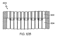
図8から図11を参照すると、本発明では、マイクロチャネルユニット操作間でのマニホルドの使用は必要ではない。例示的な形態では、ユニット操作502の第1のユニット操作又は区画からの複数の流出流れは、下流ユニット操作504の下流ユニット操作又は区画内の同様の数又は等しい数の入口チャネルに供給される。同じユニット操作のユニット操作間又は区画間のこのインタフェースは、マイクロチャネルの維持と呼ばれる。マイクロチャネルの維持を用いると、流れは、下流ユニット操作又は区画に入った時に第1のユニット操作又は区画において流路に直交する方向に実質的な向きを変えたり、その方向に移動しない。第1のユニット操作又は区画と下流ユニット操作又は区画との間の接続部での得られる圧力損失は、従来技術のマニホルド設計で受ける圧力損失の10%未満とすることができる。マイクロチャネルユニット操作又はユニット操作区画間でマイクロチャネルの維持を実施する例示的な構造を図8から図11に示している。
With reference to FIGS. 8-11, the present invention does not require the use of a manifold between microchannel unit operations. In an exemplary form, multiple outlet streams from the first unit operation or compartment of
図12を参照すると、メタノールの生成は、システム内のメタノール濃度、システム圧力、システム温度、及び合成ガス反応剤が合成触媒と接触している滞留時間に依存する。等電位マイクロチャネル反応器104又は平行等電位マイクロチャネル反応器104は、メタノール合成のような平衡により制限された反応に対して高い単一通過の転換を達成する例示的な方法である。温度が反応器長に沿って下がった場合、転換の平衡電位が増大する。例示的な形態では、3ステージ直列反応器104は、単一のモジュール内に構成され、容積及び温度は、所要の入口流量が得られるように全反応器容積及び接触時間を最小にするために、商業レベルのメタノール合成触媒の反応速度論に基づいて最適化される。接触時間は、粒子状形触媒を含む全反応器容積を標準状態での反応剤の全容積流量によって割ったもので定められる。上述の合成反応器104においては、750ミリ秒の接触時間により、3ステージ反応器内での70.5%という全CO転換が得られる。
Referring to FIG. 12, the production of methanol depends on the methanol concentration in the system, the system pressure, the system temperature, and the residence time that the syngas reactant is in contact with the synthesis catalyst. The
例示的なメタノール合成マイクロチャネル反応器104では、処理流体及び熱交換流体の横流を取り入れる。3つの異なる反応帯域が、反応器200、202、204の縦方向に沿って設計される。第1の反応帯域200は、全反応チャネル長の20%、すなわち、1mの長さチャネルの0.2mである。第2の反応帯域202は、チャネル長中間点まで1m長さチャネルの0.3mだけ延びている。第3で最終反応帯域204は、中間点(0.5m)からチャネル端部まで延びている。メタノール合成マイクロチャネル反応器104の反復ユニット幾何学的形状は、図3に示されている。この設計では、反応器当たりの全触媒容積と全反応器容積の比率を30%超まで、一部の更に別の例示的な実施形態では、70%超まで増大させる。この高い触媒容積比により、蒸気メタン改質と比較してメタノール合成の反応時間延長が相殺され、かつ適度の数の反応器アセンブリが得られる。これらの設計寸法に基づいて、1日につき500メートルトンのメタノールには、合計9つのアセンブリが必要である。各メタノール合成アセンブリは、1m(幅)x1.2m(高)x3.9m(長)であり、蒸気メタン改質器アセンブリのサイズに同一である。3つのアセンブリの得られるスタック高さは、7m未満である。
The exemplary methanol
図4、図12、及び図13を参照すると、触媒(図示せず)を収容する反応マイクロチャネル154内のメタノールの高濃度化により、反応が平衡により制限されるので合成ガスをメタノールに転換する反応の頻度が減り、従って、炭素転換率では、メタノールへの合成ガス生成物の全体的な転換率が下がる。従って、合成ガス流れ内のメタノール濃度を低減することは有利である。統合マイクロチャネル熱交換器及び凝縮器170は、第1の冷却ステージ162の直後にあり、3組のマイクロチャネル174、176、178を含む。第1の組のマイクロチャネル174は、冷却マイクロチャネル164から下流にあり、熱的に連通するように温度が下がった合成流れを運び、冷却流体は、沸騰温度未満にメタノール生成物の温度を下げるために第2の組のマイクロチャネル176を通って流れる。この例示的な凝縮器170においては、冷却流体は、液体の水である。それによってメタノール及び未反応合成ガス、並びに一部の副産物の水を含む2相合成流れをもたらす。第1の組のマイクロチャネル174は、毛細管排除区画138と連通するように2相流を運ぶ。
Referring to FIGS. 4, 12, and 13, synthesis gas is converted to methanol because the reaction is limited by equilibrium due to the high concentration of methanol in
図13を参照すると、マイクロチャネルプラント100の液体捕捉(水、メタノールを問わず)は、毛細管排除の原理に基づいている。例示的な毛細管排除区画138は、そうでなければ隣接するマイクロチャネル174、178を架橋する小孔210を有する材料を含む。小孔210の片側でのP1での圧力は、孔の反対側のP2よりも大きい。従って、液体が孔210と接触した時、毛管圧力は、気体の漏出圧力よりも大きく、従って、液体は、強制的に孔210を通って出口マイクロチャネル178に入る。円形の孔に対して、この関係は、以下に方程式2で示している。
Referring to FIG. 13, the liquid capture (whether water or methanol) of the
![]()
![]()
ここで、σ=気体と液相の間の表面張力、r=単一の孔の半径である。あらゆる形状の孔を使用することができ、これには、水圧半径を使用する同等の式に方程式(2)を修正する必要があると考えられる。依然として第3の組のマイクロチャネル178の凝縮メタノールは、毛細管排除区画138から運び去られてメタノール蒸留ユニット118に運び出される。
Where σ = surface tension between the gas and liquid phases, r = radius of a single hole. Any shape of hole can be used, which would require the modification of equation (2) to an equivalent equation using the hydraulic radius. Still, the condensed methanol in the third set of
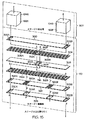
図14及び図15を参照すると、平行反応器104A、104Bは、共通マイクロチャネル熱交換器及び凝縮器170にメタノール、未反応合成ガス、及び合成反応副産物(生成物流れ)を含む蒸気流れを送出するように構成することができる。凝縮器170の第1の端板300は、平行反応器104A、104Bのそれぞれの第1の冷却ステージ162A、162Bから生成物流れを受け取る開口部302A、302Bを提供する。矢印A及び矢印Bは、凝縮器170を通って流れる生成物流れの流体流れを表している。第1の板300に隣接した第2の板304は、遠端で第1の板302A、302Bを通って流れる生成物流れを受け取るマイクロチャネル306A、306Bを含む。生成物流れは、これらのマイクロチャネル306A、306Bに沿って流れ、生成物流れの蒸気相からメタノールの少なくとも一部を凝縮するために隣接板(図示せず)内に形成された隣接マイクロチャネルを通って流れる冷却流体(図示せず)により冷却される。第3の板308は、毛細管排除区画318A、318Bを含む第4の板316内で形成された2相生成物混合物を別の組のマイクロチャネル314A、314Bに送出する第2の板を貫通する開口部312A、312Bに整列する開口部310A、310Bを含み、そこで、液相は、第5の板322の整列したマイクロチャネル320A、320Bを通じて抜かれる。第6の板326を貫通する開口部324A、324Bは、第5の板322のマイクロチャネル320A、320Bに整列し、かつ液体生成物を蒸留ユニット(図示せず)に運ぶ。マイクロチャネル314A及び314Bを通って流れる比較的乾燥した気体生成物は、気体の成分が開口部328A、328B、330A、330Bを使用する第2の反応器ステージ202に入る前に復熱式に加熱される。図14と図15の間の大きな差は、図15が、マイクロチャネル熱交換器及び凝縮器170内で復熱式熱交換を使用する時に特に有利である対掌性実施形態を示すということである。
14 and 15,
図16を参照すると、例示的な流れ図が、復熱式熱交換が利用される平行反応器104A、104Bに対して示されている。復熱式熱交換では、第1の冷却ステージ162から流入する暖かい流れを使用して、マイクロチャネル熱交換器及び凝縮器170からの出口気体流れを加熱する。このようにして、第1の冷却ステージからの暖かい流れからのエネルギは、この蒸気のエンタルピーを増大させるために出口気体流れと交換される。このエンタルピー増大は、メタノールへの合成ガス転換率増大を得るための好ましい反応速度論をもたらすために有利である。
Referring to FIG. 16, an exemplary flow diagram is shown for
再び図12を参照すると、第2の反応器ステージ202は、マイクロチャネル熱交換器及び凝縮器170から直ちに下流である。第2の反応器ステージ202のマイクロチャネルは、熱交換器及び凝縮器170から直接に気体反応剤(合成ガス)を受け取り、マイクロチャネル内に充填するか、マイクロチャネル壁に沿って裏張りするか、又は第1の反応器ステージ152のマイクロチャネル内で他の方法で形成するか又は成長させることができる合成触媒にこれらの反応剤を導入する。成長した触媒は、反応、メッキ、又は架橋して、又は他の方法でチャネル壁間の多孔質接続部を形成する溶液中又は懸濁液中の前駆体を含む触媒を含む。空隙率は、マクロ多孔性、メソ多孔性、又は微小孔性、又はこの3つのあらゆる組合せとすることができる。上述のように、メタノール合成は、平衡に依存し、かつ凝縮器170内のメタノールの引き抜きにより、残留合成ガス反応剤間の反応の頻度を増大させるように作動するマイクロチャネル202内のメタノール濃度が低下し、従って、炭素転換率では、メタノールへの合成ガス生成物の全体的な転換率が下がる。
Referring again to FIG. 12, the
第2の熱交換器及び凝縮器190は、図13の第1の熱交換器及び凝縮器170に類似した3組のマイクロチャネル(図示せず)を含む。第1の組のマイクロチャネルは、第2の反応器ステージ202からの生成物を運ぶ第2の組のマイクロチャネルと熱的に連通するように液体の水を運ぶ。生成物と水の間のエンタルピー差は、エネルギが生成物から液体の水に伝達され、従って、第2の組のマイクロチャネルを通って流れる生成物内でメタノール成分の凝縮が発生するようなものである。第2の組のマイクロチャネルからの凝縮メタノール及び副産物処理コンデンセート/水は、第3の組のマイクロチャネルで運び去られて、メタノール蒸留ユニット118に運ばれる。熱伝達マイクロチャネルから生成された温水は、プラント100内で他の処理流れを加熱するために使用することができ、一方、第2の組のマイクロチャネルの残留気体成分は、第3の反応器ステージ204に供給される。
The second heat exchanger and
第2の熱交換器及び凝縮器190から直ちに下流である第3の反応器ステージ204は、第2の熱交換器及び凝縮器190からの気体反応剤(合成ガス)を受け取る分配マイクロチャネルを含み、マイクロチャネル内に充填するか、マイクロチャネル壁に沿って裏張りするか、又はマイクロチャネル内で他の方法で構成することができる合成触媒にこれらの反応剤を導入する。上述のように、メタノール合成は、平衡に依存し、かつ凝縮器190内のメタノールの引き抜きにより、残留合成ガス反応剤間の反応の頻度を増大させるように作動するマイクロチャネル内のメタノール濃度が低下し、従って、炭素転換率では、メタノールへの合成ガス生成物の全体的な転換率が90%近くに上がる。この第3の反応器ステージ204は任意的であり、必ずしも全ての用途に利用することができるわけではないことは理解されるものとする。
The
第3の熱交換器及び凝縮器194は、図13の第1の熱交換器及び凝縮器170に類似した3組のマイクロチャネル(図示せず)を含む。第1の組のマイクロチャネルは、第3の反応器ステージ204からの生成物を運ぶ第2の組のマイクロチャネルと熱的に連通するように液体の水を運ぶ。生成物と水の間のエンタルピー差は、エネルギが生成物から液体の水に伝達され、従って、第2の組のマイクロチャネルを通って流れる生成物内でメタノール成分の凝縮が発生するようなものである。第2の組のマイクロチャネルからの凝縮メタノールは、第3の組のマイクロチャネルで運び去られて、メタノール蒸留ユニット118に運ばれる。第1の組のマイクロチャネルで生成された温水は、予熱流体又は蒸気前駆体としてプラント100で利用され、一方、残留気体成分(残留合成ガス反応剤及び副産物)は、蒸気改質器102内で利用される。内蔵型相分離チャネルを有するマイクロチャネル熱交換器を使用して1日当たり1000メートルトンのメタノールのプラント機能のメタノール合成区画は、ほぼ1m(幅)x1.2m(高)x3.9m(長)の1つのアセンブリ104に適合するようにサイズ決定される。例示的なマイクロチャネル装置サイズは、1日当たり1000メートルトンのメタノールにつき200m3未満、より好ましくは、1日当たり1000メートルトンのメタノールにつき80m3未満、更に一層好ましくは、1日当たり1000メートルトンのメタノールにつき10m3未満のメタノール合成反応器104に対して変動する。
The third heat exchanger and
図1を参照すると、メタノール蒸留ユニット118は、プラント100全体の熱的統合を改善するために加圧下で操作される。48バール蒸留ユニットの温度範囲は、200℃から242℃である。これは、周囲圧力で80から120℃の蒸留温度範囲に同等のものである。非凝縮性気体流れは、液体及び気体の逆流に対して20段マイクロチャネル蒸留ユニット118に入る前に液体から分離される。メタノールは、95%よりも大きい純度で蒸留ユニットの上部側流から回収され、水は、99%よりも大きい純度でユニット底部から回収される。水は、蒸気改質器102の供給流れに移動する前に、メタノール合成反応器104の冷却水に再循環される。メタノール蒸留ユニット118では、6つのマイクロチャネルアセンブリを使用し、各アセンブリは、1.2m(高)x1m(幅)x3.9m(長)である。
Referring to FIG. 1, the
上述の例示的な実施形態によれば、メタノール生成物純度の範囲は、80から90%の間、好ましくは、95%から99%超の間である。水純度の範囲は、80から90%の間、好ましくは、95%から99%超の間である。更に、メタノール蒸留ユニット容積生産性の範囲は、1日当たりの1000メートルトンのメタノールに対して10から25m3の間、好ましくは、1日当たりの1000メートルトンのメタノールに対して25から100m3超の間である。更に別の水の範囲は、25から50%、好ましくは、50%から65%超の間である。 According to the exemplary embodiment described above, the range of methanol product purity is between 80 and 90%, preferably between 95% and more than 99%. The range of water purity is between 80 and 90%, preferably between 95% and more than 99%. Furthermore, the methanol distillation unit volumetric productivity range is between 10 and 25 m 3 for 1000 metric tons of methanol per day, preferably between 25 and more than 100 m 3 for 1000 metric tons of methanol per day. Between. Yet another range of water is between 25 and 50%, preferably between 50% and over 65%.
例示的な蒸留ユニット118をメタノール蒸留に対して説明したが、他の組成を同様にプラント100によって生成及び蒸留し、他の化学反応処理によって生成される生成物の望ましい純度をもたらすことができる。例えば、蒸留ユニットは、以下の種類の化合物、すなわち、アルカン、アルケン、アルキン、ナフタレン、及び他の環状化合物、芳香族化合物、及びアルデヒド、アルコール、ケトン、カルボン酸、及びニトリルを含む酸素化物のうちの少なくとも1つを含む混合物を含む炭化水素を分離する分留器として機能するように適応させることができる。蒸留ユニットはまた、無機化合物又は天然由来物質含む混合物を分離することができる。分留器は、エタン−エチレン分留器又はヘキサン−シクロヘキサン分離器のような近沸騰化合物を分離することができる。例示的な形態では、液体入口流れは、84%のヘキサン及び16%のシクロヘキサンを含有し、蒸気入口流れは、9%のヘキサン及び91%のシクロヘキサンを含む。出口液体生成物流れは、入口蒸気流れより僅かに下方にある点で除去され、7%のヘキサン及び93%のシクロヘキサンを含んでいた。チャネルは、5インチのチャネル長に15個の平衡ステージを発生させた。ユニットにわたる温度範囲は、69℃から83℃間で変化した。エタン−エチレン及びシクロヘキサン−ヘキサン(参考「ChemCAD(登録商標)5.5.0」成分ライブラリ)の相対揮発度は、水及びメタノールより大幅に厳しいものである。
Although the
方程式2に示すような理論板同等高さ(HETP)の推定は、マイクロチャネル内での対流時間及び拡散時間の均衡を取ることに基づいている。単一ステージの対流の固有時間は、ステージ長を平均流速で割ったものによって定められる。単一ステージにおける拡散の固有時間は、拡散距離の二乗を流体拡散率で割ったものによって定められる。2つの固有時間を等しく設定すると、相平衡の所要HETPの簡単な推定値を解くことができる。類似した方法は、化学反応における触媒壁への拡散に対して成功することが証明されており、類推により蒸留に対して評価されたものである。
Estimating the theoretical plate equivalent height (HETP) as shown in

マイクロチャネル蒸留は、Tonkovich他によるUS2006/0016216に説明されており、本明細書において引用により組み込まれている。US2006/0016216に説明されている装置を使用したシクロヘキサン−ヘキサン分離のマイクロチャネル蒸留実験では、1.35ミリメートル(mm)の気体チャネルに隣接してステンレス鋼製金網上に流液体を流すことにより0.178mmの液膜を作り出すものであった。液体速度は、1mm/秒(s)であり、液体拡散率は、5x105cm2/sであった。液体側の得られる予測HETPは、方程式2を用いると0.63cm台であった。気相拡散率は、0.0342cm2/sであり、平均気体流速は、0.015m/sであり、気体チャネル間隙は、1.35mmであった。得られる予測気相HETPは、0.8cmであった。気相の予測HETPが液相より高かったことは、幾分驚くべきことであったが、これは、両方の流体に対してチャネル設計の均衡を取ることの重要性を明らかにしている。組成の変化に基づいて、実験的なHETPは、0.83cmと計算された。高速化時に行った更に別の実験により、HETPが速度にほぼ反比例していることを確認された。これは、HETPの大体の予測に対して注目に値する合致点であり、他のマイクロチャネル蒸留ユニットにおけるHETPの良好な定性的予想値と考えられる。
Microchannel distillation is described in US 2006/0016216 by Tonkovich et al., Which is incorporated herein by reference. In a microchannel distillation experiment with cyclohexane-hexane separation using the apparatus described in US 2006/0016216, a flow liquid is run over a stainless steel wire mesh adjacent to a 1.35 millimeter (mm) gas channel. A liquid film of 178 mm was created. Liquid rate was 1 mm / sec (s), the liquid spreading rate was 5x105cm 2 / s. The predicted HETP obtained on the liquid side was on the order of 0.63
1cmのHETPは、気体薄膜と接触する液体薄膜のHETPが方程式2により近似される分離原理に基づいて、メタノール蒸留ユニットの設計基準に利用される。しかし、以下に限定されるものではないが、5cm未満、2cm未満、1cm未満、0.1cm未満のような他のHETPを利用することもできるであろう。25ミクロンの膜厚及び0.015m/sの速度に対して、HETPは、1cmに近づく。気体チャネルは、気体と液体間のチャネル間隙比率を10未満に維持することにより、0.1cm未満の予測HETPを有する。そうすることにより、気体チャネルの拡散距離の二乗は、液相よりも気相拡散率で3桁の低減よりも大きくオフセットされる。HETPを利用して、蒸留及び吸着のような気体液体接触ユニット操作の効率を説明することができる。本発明の好ましいHETP範囲は、10cm未満、又は5cm未満、又は1cm未満、又は0.5cm未満である。
1 cm of HETP is used as a design criterion for the methanol distillation unit based on the separation principle that the HETP of the liquid film in contact with the gas film is approximated by
合成反応器104内でメタノールで同時に生成される水は、次に、加圧マイクロチャネル蒸留ユニット118を通じてメタノールから除去される。メタノールは95%超まで浄化されて、浄化生成物導管198を通じて蒸留ユニット118から排出される。蒸留ユニット118の水は、マイクロチャネル熱交換器及び相分離器130に送られる。
The water that is simultaneously generated with methanol in the
水は、合成反応器104に向けて3つの供給源、すなわち、湿潤合成ガス流れ、メタノール蒸留ユニット118、及び任意的に燃焼排出流れからプラント100内で再循環される。従って、アルコール、炭化水素、エーテルなどのような水流内の少量の反応副産物は、水再循環における堆積を軽減するマイクロチャネル蒸気改質器102内で容易に改質されることが予想される。
Water is recycled into the
コンピュータシミュレーションを利用して、1日当たり1、000メートルトンのメタノールを生成するようにプラント100を拡張した。このケースに対しては、各反応区画は、表IIに示す温度及び圧力条件で保持される。このケースには、メタノール反応ユニットに統合したメタノールコンデンセート除去、及び相分離及び復熱式熱交換のための対応する温度降下は含まれない。表Iは、主要なユニット操作の流量及び熱負荷を詳細に示すものである。例えば、マイクロチャネル蒸気改質器102に供給される全水量は、39.9メートルトン/時間である。このうちの23.3メートルトン/時間のみが、システム内の水捕捉及び再利用の理由で独立水源からのものである。蒸気改質器102の排出からの水も捕捉される場合、必要とされる淡水全量は、16.4メートルトン/時間である。これは、65%という所要全水量の正味低減を表している。
Utilizing computer simulation, the
(表I)
表IIは、例示的な3区画合成反応器104の各区画に関連の温度、圧力、容積、及び熱負荷を詳細に示すものである。
Table II details the temperature, pressure, volume, and heat load associated with each section of the exemplary three-
(表II)
第2のコンピュータシミュレーションを利用して、1日当たり1、000メートルトンのメタノールを生成するようにプラント100を拡張した。この場合、反応器区画の各々は、250Cの温度、及び第1のステージ入口の50バールから第3のステージ出口での48.8バールに減少する圧力に維持した。メタノールコンデンセート除去及び復熱式熱交換は、反応ステージの間に組み込んだ。表IIIは、主要なユニット操作の流量及び熱負荷を詳細に示すものである。例えば、マイクロチャネル蒸気改質器102に供給される全水量は、56.6メートルトン/時間である。このうちの33メートルトン/時間のみが、システム内の水捕捉及び再利用の理由で独立水源からのものである。蒸気改質器102の排出からの水も捕捉される場合、必要とされる淡水全量は、23.3メートルトン/時間である。これは、65%という所要全水量の正味低減を表している。
Utilizing a second computer simulation, the
(表III)
第3のコンピュータシミュレーションを利用して、1日当たり1、000メートルトンのメタノールを生成するようにプラント100を拡張した。この場合、反応器区画の各々は、240Cの温度及び33バールの圧力に維持した。メタノールコンデンセート除去及び復熱式熱交換は、反応ステージの間に組み込んだ。表IVは、主要なユニット操作の流量及び熱負荷を詳細に示すものである。例えば、マイクロチャネル蒸気改質器102に供給される全水量は、56.6メートルトン/時間である。このうちの33メートルトン/時間のみが、システム内の水捕捉及び再利用の理由で独立水源からのものである。蒸気改質器102の排出からの水も捕捉される場合、必要とされる淡水全量は、23.3メートルトン/時間である。これは、65%という所要全水量の正味低減を表している。表Vは、表III及びIVからの結果を比較するものである。
Utilizing a third computer simulation, the
3帯域等温メタノール反応器が中間ステージ生成物冷却と共に使用され、かつ液体回収が各ステージの間に含まれる時、メタノールへの天然ガス流れの転換による全体的な炭素効率は、60%を僅かに超えている。各ステージ後に生成物を除去することにより、3ステージ反応器の全体的な転換は、250Cで90%に近づけることができる。この炭素効率は、メタノールに関する他の海上固定式気体品質改善手法と競合するが、従来の陸上メタノールプラントよりも低い。この効率が低い点は、設置面積の低減及び海上生成のプラント複雑さの最小限化との交換条件である。天然ガスからのメタノール生成に向けてマイクロチャネル反応ユニット及びマイクロチャネル蒸留ユニットを兼ね備えたプラントの30%よりも大きい炭素効率は、本発明の範囲に該当することは確かである。 When a three-zone isothermal methanol reactor is used with intermediate stage product cooling and liquid recovery is included between each stage, the overall carbon efficiency due to the conversion of natural gas flow to methanol is slightly less than 60%. Over. By removing the product after each stage, the overall conversion of the three stage reactor can approach 90% at 250C. This carbon efficiency is competitive with other offshore fixed gas quality improvement approaches for methanol, but lower than conventional onshore methanol plants. This low efficiency is a trade-off with reduced footprint and minimal offshore plant complexity. A carbon efficiency greater than 30% of a plant that combines a microchannel reaction unit and a microchannel distillation unit for methanol production from natural gas is certainly within the scope of the present invention.
(表IV)
(表V)
上述のように、プラント100を通した化学反応の副産物として生成された水の回収は、特定の用途において特に重要であると考えられる。1つの水源は、マイクロチャネル蒸気改質器102内の酸素源流による天然ガスの燃焼に由来する。例示的な作動条件においては、蒸気改質器102からの排出ガスは、30℃まで冷却され、復水は、図3に示すような毛細管排除区画による毛細管排除により除去される。排出流れからの水捕捉に対しては、P1は、ほぼ103キロパスカル(kPa)である。水の表面張力は、0.0728N/mである。例えば、ほぼ25ミクロンの孔210の半径は、液体を液体回収リザーバ及びポンプステーションに移動させるほぼ5、000Paの差動圧力を可能にするであろう。
As mentioned above, the recovery of water produced as a by-product of a chemical reaction through the
図1を参照すると、再利用することができる別の水源は、蒸気メタン改質の後に残る水に由来する。湿潤合成ガス生成物流れ内の水は、圧力を掛けて除去されて、メタノール合成反応器104に流れる水冷却水流に向けて回収ヘッダに送られる。水は、凝縮器170によりメタノール合成反応器104からの排出流れからも捕捉される。また、分離は、圧力を掛けて行われ、凝縮流れは、メタノール合成反応器104の冷却液供給に向けて水ヘッダに送られ、非凝縮流れは、熱源としてマイクロチャネル蒸留ユニット118に送ることができる。
Referring to FIG. 1, another source of water that can be reused comes from the water remaining after steam methane reforming. Water in the wet synthesis gas product stream is removed under pressure and sent to a recovery header for a water cooling water stream that flows to the
図17を参照すると、本発明のプラント100の例示的な用途は、海上天然ガスプラットフォームに入渠された船舶上である。1日当たり1、000メートルトンの統合メタノール生成ユニットの配置図600は、15mx18m内に収まるように設計されている。3つの蒸気メタン改質アセンブリ602の各々は、対応するメタノール合成反応器区画604を含む。互いの上に積み重ねられた蒸気メタン改質器及び2つのメタノール反応器アセンブリの各組のデッキ(テラス)サイズは、3.9mx1mx6.3m高である。9つのアセンブリスタックは、18mの船舶デッキ空間にわたって収まり、そこで、ほぼ1mは、保守のためのアクセスができるようにアセンブリスタック間に許容されている。1組の蒸留アセンブリ606には、ほぼ3.9mx12mの設置面積が必要であり、高さは、ほぼ1mである。ここでもまた、1mのデッキ空間が、保守のためにアクセスができるように蒸留アセンブリ間に許容されている。マイクロチャネルユニット及び従来機器の得られる組合せは、18mx15mデッキ設置面積に容易に収まる。このプラント配置図は、圧縮器、ポンプ、制御システム、付加的な熱交換器も含む。これは、そうでなければ非マイクロチャネル技術に必要とされると考えられるデッキ空間と際立った対照である。
Referring to FIG. 17, an exemplary application of the
6つのアセンブリ内に収容される30個のフルスケール反応器ブロックを有する1日当たり1、000メートルトンメタノールプラントの規模は、3.9mx5.8mx3.9mである。改質反応区画の18ワット(W)/平方センチメートル(cm2)の熱流束及びほぼ14m2反応熱伝達面積/反応器という性能値でのこのプラントの完全なシステムには、アセンブリ当たり5つの反応器から成る9つのSMRアセンブリが必要である。海上メタノール合成反応システム向けに統合された各アセンブリは、ほぼ3.9m(長)x3.9m(高)x1m(幅)になる。 The scale of a 1,000 metric ton methanol plant per day with 30 full scale reactor blocks housed in six assemblies is 3.9 mx 5.8 mx 3.9 m. The complete system of this plant, with a performance value of 18 watts (W) / square centimeter (cm 2 ) heat flux and approximately 14 m 2 reaction heat transfer area / reactor in the reforming reaction zone, has 5 reactors per assembly. Nine SMR assemblies consisting of: Each assembly integrated for the offshore methanol synthesis reaction system will be approximately 3.9 m (long) x 3.9 m (high) x 1 m (width).
図18を参照すると、上述の主要な例は、メタノール合成のためのものであるが、本発明は、複数のユニット操作を結合して単一のブロック500に又は複数のサブアセンブリを結合して統合反応器ブロック500にするのに等しく有用である。組付け後に単一の構成要素を形成するように積み重ねるか又は組み込む2つ又はそれよりも多くの固有の箱を使用することができる複数のユニット操作と共に統合反応又は分離システムを組み立てることが好ましいであろう。
Referring to FIG. 18, the main example described above is for methanol synthesis, but the present invention combines multiple unit operations to combine a
この例においては、1つの供給流れ582は、分配及び混合区画548の上部に入り、第2の供給流れ506は、側面から入って、反応器区画552に入る前に十分な均一性に混合されて第1の供給流れ582に入る。熱交換流体流れ514は、反応器区画552に入って、化学反応が行われる反応区画552のマイクロチャネルと熱的に連通する。反応区画552からの得られる生成物は、反応器区画552端部と接合されている分離及び熱交換区画510に供給され、熱交換区画510は、そこから出る2つの生成物流れ516、518を含む。
In this example, one feed stream 582 enters the top of the distribution and
図5を参照すると、区画548、552、510は、シム又は積層体から製造されて、チャネル流路が合成反応器104に類似した方法でサブアセンブリ端部まで遙かに延びることを可能にするために、選択的に部分的にエッチングされる。この特徴及び従って流れ通路は、マイクロチャネル寸法内である少なくとも1つの寸法を有する。流体の少なくとも1つの出口は、装置の端部まで延びる(上図では左から右に第1及び第4の積層体で示すように)。装置端部まで延びることにより、流れ通路は、流体が実質的な流れ回収及び再分配なく進むことができるように第2の形式のサブアセンブリ内の流れチャネルに整列することができる。実質的な流れ回収及び再分配により、いずれか1つのチャネル内で最大20%までの流れ、より好ましくは、10%未満の流れ、及び更により好ましくは、いずれか1つのチャネル内の流体の2%未満が、第2のアセンブリにおいて対応する流れチャネル以外のチャネルに移動する可能性がある。一実施形態では、チャネルは、殆どが第1及び第2のアセンブリから1対1にマップすることができ、第1のサブアセンブリ内の各チャネルを出る流体は、第2のサブアセンブリ内の1つのチャネルにマップされる。代替的な実施形態では、第1のサブアセンブリ内の2つ又はそれよりも多いチャネルからの流体は、第2のサブアセンブリ内の1つのチャネルにマップされる。代替的な実施形態では、第1のアセンブリ内の1つのチャネルからの流体は、第2のサブアセンブリ内の2つ又はそれよりも多いチャネルにマップされる。流体は、第1及び第2のサブアセンブリを他のチャネルと分離するプレナム内では実質的に漏出したり又は直交して進んだりしない。流体は、複数の小さなチャネルから、その後に流れ方向を変えて第2のサブアセンブリのチャネルの第2のアレイに再分配される1つの大きなチャネルに回収されたりしない。第1及び第3の区画548、510は、3つの区画548、552、510の全てを通る流路が実質的な流れの統合なく全体的に延びるように第2の区画552と嵌合する。
Referring to FIG. 5, compartments 548, 552, 510 are manufactured from shims or laminates to allow the channel flow path to extend far to the subassembly end in a manner similar to
図8から図11に示すように、2つのアセンブリ(548から552又は552から510)を嵌合又は接合する複数の方法がある。図8に示す第1の実施形態600においては、第1の区画548又は552のチャネル(図8では502と表す)は、第1の区画548又は552のチャネル出口近くでチャネル断面が低減し、かつ第2の区画552又は510(図8では504と表す)の入口に当接する。本方法により、2本のチャネルの許容誤差が緩められ、それによってそれぞれ第1及び第2の区画内の第2のチャネルの隣への第1のチャネルの正確な配置はより大きな誤差の程度を有するが、それでも第1及び第2の区画内の流体チャネル間の妨害されない接続を作り出すことができる。
As shown in FIGS. 8-11, there are multiple ways to fit or join two assemblies (548 to 552 or 552 to 510). In the
図9を参照すると、第2の例示的な実施形態602においては、第1の区画上の流れチャネルでは、局所点では断面の低減はないが、接続点で第1及び第2のサブアセンブリのチャネルの一方のチャネル寸法がアラインメントの問題を緩和するように他方よりも小さいように第1のアセンブリで流れ長さを通して断面が小さくなる。
Referring to FIG. 9, in the second
図10を参照すると、第3の例示的な実施形態604においては、第1の区画のための流体チャネルは、チャネル間の金属に延びる溝を作り出し、それによって溝が明確なアラインメントのために波形の上に適合するように設計されている。溝は、アラインメントが容易であるように舌状部からはみ出ている。
Referring to FIG. 10, in a third
図11を参照すると、第4の例示的な実施形態606においては、開放プレナムは、第1及び第2の区画間で流体チャネルを分離する。この例に対しては、流体は、第1及び第2の区画に実質的に直線的に進む。流体は、第1及び第2のサブアセンブリを分離するプレナム内では実質的に再分配されない。流体は、サブアセンブリ間でチャネルからチャネルに、又は第1及び第2の区画間で1つのチャネルから2つ又はそれよりも多くのチャネルに又は2つ又はそれよりも多いチャネルから1つのチャネルにそれぞれ通常の方法でマップされる。
Referring to FIG. 11, in a fourth
2つの区画の接合、更に同様に製造されるが各個々の区画が接合された後に接合される2つの区画の付加的な利点は、触媒又は吸着剤統合の容易さから生じるであろう。端部以外の点で装置を壊す機能は、触媒又は収着剤を追加するか又は除去して再装荷する使用を可能にすることができる。この手法は、区画の一部を失うことなく反応器の芯又は収着剤を交換する効果を可能にすることができる。第2の区画の触媒が仮にヒューズを溶融して第2の区画から除去することができなくなった場合、新しい区画又は第2の区画を追加するか又は従来の第1の区画と統合して装置をまた使用することができる。この手法は、単相又は多相の用途にも有用であろう。この手法が役立つユニット操作には、化学反応、熱交換、混合、流体分配、分離、蒸留、吸着、吸着、分類、及びその他がある。 The additional advantage of joining two compartments, and also two compartments that are manufactured similarly, but joined after each individual compartment has been joined, will result from the ease of catalyst or adsorbent integration. The ability to break the device at a point other than the end can allow use to add or remove catalyst or sorbent and reload. This approach can allow the effect of changing the reactor core or sorbent without losing part of the compartment. If the second compartment catalyst melts the fuse and cannot be removed from the second compartment, a new compartment or a second compartment is added or integrated with the conventional first compartment Can also be used. This approach may also be useful for single-phase or multiphase applications. Unit operations for which this approach is useful include chemical reactions, heat exchange, mixing, fluid distribution, separation, distillation, adsorption, adsorption, classification, and others.
1つ又はそれよりも多くの統合マイクロチャネルユニット操作ブロックが加圧格納船舶内に収容されることも本発明の範囲である。例示的な船舶は、米国特許出願出願番号第10/774298号(2005年8月11日公開のUS2005/0175519)に開示されており、これらの開示内容は、本明細書において引用により組み込まれている。
It is also within the scope of the present invention that one or more integrated microchannel unit operating blocks are housed in a pressurized containment vessel. Exemplary ships are disclosed in US patent application Ser. No. 10 / 774,298 (
図4から図6を改めて参照すると、フィッシャー・トロプシュ(FT)反応と一般的に呼ぶ代替の例示的な反応を図示の構造体を使用して高縦横比マイクロチャネルで実行することができる。本発明の開示に向けて、高縦横比は、約2よりも大きい高さ:幅の比率を含む。この例示的な反応においては、第1の反応器ステージ152では、一酸化炭素及び水素が様々な形の液化炭化水素に転換される化学反応を実行する。このFT反応器148は、高い熱伝導率材料(すなわち、20W/m−Kよりも大きい熱伝導率を有する材料)から製造される波形インサート700を組み込んでいる。第1の組のマイクロチャネル154は、ほぼ1から60インチの縦方向チャネル長を有するように対向平面シート702間に挟持される直角波形インサート700を協働使用して形成される。しかし、60インチよりも大きいマイクロチャネル長を利用することも本発明の範囲である。従って、各マイクロチャネルは、3つの側面で波形インサートにより、第4の側面では平面シートのうちの1枚によって形成される。従って、FT反応中にマイクロチャネル154内で生成された熱は、高温点を更に抑制して冷却液チャネル158上での乾燥可能性を低減するように流体流れ方向に縦方向に波形インサート700を通って流れることができる。例示的な形態では、冷却液マイクロチャネル158は、FT反応の熱を除去するために一部沸騰される水を収容する。
Referring again to FIGS. 4-6, an alternative exemplary reaction, commonly referred to as a Fischer-Tropsch (FT) reaction, can be performed in a high aspect ratio microchannel using the illustrated structure. For purposes of the present disclosure, a high aspect ratio includes a height: width ratio greater than about 2. In this exemplary reaction, the
当業者に明らかなように、冷却チャネル158のサイズ決定は、所要の全体的な熱伝達負荷、並びにインサート700及びシート702の所要熱流束に依存するであろう。更に、反応器全体148は、銅のような高熱伝導率材料から製造することができる。本発明の反応器148の例示的な寸法には、ほぼ0.125インチの反応マイクロチャネル高さ、ほぼ0.04インチの幅及びほぼ1から60インチの長さが含まれる。更に、例示的なシート702の厚みは、ほぼ0.02インチであり、一方、例示的な波形インサート厚み(シート自体の)は、ほぼ0.006インチである。
As will be apparent to those skilled in the art, the sizing of the
図19を参照すると、図4から図6の反応器の例示的な部分断面には、粒状形態で、対向する熱伝達壁間の間隙に実質的に及ぶようにマイクロチャネル154内に詰められたFT触媒706が含まれる。上述のように、各マイクロチャネル154の横側面は、波形インサート700を含み、一方、各マイクロチャネルの上部及び底部は、インサート及び平面シート702を含む。このマイクロチャネル反応器154の反復するユニットは、点線により示されている。代替の例示的な実施形態では、波形インサート700は、FT反応による大部分の熱が熱伝達マイクロチャネル158に向けて流れるように、単一の平面シート702及び対応するマイクロチャネル158と共に使用することができる。FT触媒粒子706は、最低2つの平均的触媒粒径がインサート700の対向側壁間に及ぶことができるようなサイズに維持されることが好ましい。例えば、触媒粒子706の主要な寸法(すなわち、平均直径)は、インサート700の対向側壁間の距離より少なくとも3倍小さいとすることができる。しかし、小さい触媒粒子706を利用してインサート700の対向壁幅:粒径の1:1より少ない比率をもたらすことができる。換言すれば、ほぼ1mmの対向壁距離に対しては、300ミクロン及びそれ未満(100ミクロン又はそれ未満を含む)のような500ミクロン又はそれ未満の粒径であれば適切である。このようにして、例示的な反応器148により、固定反応器容積に追加すべき触媒の高質量化が可能であり、従って、非テイラー流パターンを有する反応器からのより高体積の生産率が可能になる。
Referring to FIG. 19, exemplary partial cross-sections of the reactors of FIGS. 4-6 are packed in
更に別の代替的な実施形態では、FT反応器148には、マイクロチャネル154内に触媒706及び不活性物質(図示せず)を部分的に詰め込むことができる。不活性物質は、冷却マイクロチャネル158の直近ではない領域で、反応チャネルの上部、底部、又はその両方に詰め込むことができる。一部の例示的な実施形態では、不活性成分は除去されて触媒と交換される。その理由は、冷却マイクロチャネル158の直近ではない(同じ軸線方向平面において)これらの領域内で生成された反応熱が、下流(反応器先端で詰め込まれた触媒の場合)又は上流(反応器出口面で詰め込まれた触媒の場合)で高熱伝導率インサート700に沿って縦方向に(又は軸線方向に)利用可能な冷却マイクロチャネル158に進むことができるからである。詰め込まれた触媒は、インサート700に開く反応器面の上部及び底部に当接する発泡体又はスクリーン材料を使用して保持することができる。当接材料は、粒子状触媒706の平均粒径よりも小さい平均開口部を有する。
In yet another alternative embodiment, the
図20を参照すると、FT反応器148の出口面は、1つよりも多い平行マイクロチャネルからの流れを集めて回収管への移動を可能にするフッターに接合される。生成物フッターは、反応で同時に生成される液体及びワックスの自由な流れを容易にするために、角度又はテーパ付きで設計されることが好ましい。平行平面から反応器の出口面まで測定される傾斜角は、好ましくは、1度よりも大きく、より好ましくは、5度よりも大きく、更により好ましくは、10度よりも大きい。一部の好ましい実施形態では、フッターは、1つよりも多い傾斜角を有することができ、FT反応器148の出口面に接続する中心部、側面、又は他のポートに排水することができる。
Referring to FIG. 20, the exit face of the
図21及び22を参照すると、代替FT反応器800は、複数の積層体802、804を使用して製造することができる。各図は、A、B、A、B、A、Bのパターンで積み重ねられた時に、幅1mmのFT反応マイクロチャネル(図19に示すものと同様)及び幅0.5mmの冷却マイクロチャネル(図19に示すものと同様)を有するように寸法決めされた反応器800を作り出す銅製シムから製造された別々のシムパターンを示している。上部シム(図21)のマイクロチャネルの高さは、1から20mmの範囲とすることができる。下部シム(図22)のマイクロチャネルの高さは、0.05から5mmの範囲とすることができる。接合、ろう付け、又は他の方法で密接に接合された後に、反応器800は、FT触媒を受け取るために背が高いチャネルを開くように切り取られた左右の側面を有することが好ましい。2つの端板(図示せず)が、反応器800の両側に追加される。各端板は、水又は別の冷却媒体に連結するために入口及び出口接続部を含む。冷却機構は、沸騰又は対流熱伝達を利用することができる。この反応器800は、最高の熱除去率を反応器床の上部での熱除去の最高発生点に適合させるために冷却液の並行流(又は逆流)を提供する。
Referring to FIGS. 21 and 22, an
図23及び24を参照すると、代替FT反応器820は、シム822、824から製造して、熱伝達流体の流れがシム厚み方向に直交して移動する半直交パターンで統合FT反応器を製造することができる。
Referring to FIGS. 23 and 24, an
図25から図30を参照すると、モデル計算が、例示的な反復ユニット(破線概略線を使用して図19に例示的な形で図示)に行われた。この反復ユニットの境界は、銅リブ中央部を通って切断されている。モデル領域は、処理チャネル全長に延びている。以下に限定されるものではないが、2つの側面での周期的壁境界、冷却チャネルに対向する壁上の一定温度(220Cに設定)のようないくつかの境界条件が計算のために仮定され、質量流束は、300マイクロ秒の接触時間が得られるように指定され、供給材料内のCOに対するH2の比率は2で、残りは10%N2であり、供給温度は、壁温と同じ値に設定され、最後に、反応器出口圧力は、350psiに設定されている。更に、触媒床特性は、ほぼ0.35の空隙率を示し、ほぼ0.3W/m−Kの有効熱伝導率を有するように仮定されている。 Referring to FIGS. 25-30, model calculations were performed on an exemplary iteration unit (shown in exemplary form in FIG. 19 using a dashed outline). The boundary of this repeating unit is cut through the center of the copper rib. The model region extends the entire length of the processing channel. Some boundary conditions are assumed for the calculation, such as but not limited to: periodic wall boundaries on two sides, constant temperature on the wall facing the cooling channel (set to 220C). , mass flux, 300 contact time microseconds specified so as to obtain, in a ratio of H 2 to CO in the feed is 2, the remainder being 10% N 2, supply temperature, wall temperature Prefecture Set to the same value, and finally the reactor outlet pressure is set to 350 psi. Furthermore, the catalyst bed characteristics are assumed to exhibit a porosity of approximately 0.35 and have an effective thermal conductivity of approximately 0.3 W / m-K.
複合FT反応システムは、図25に示す6つの反応を使用してモデル化される。C1からC4を生成する反応は、理想的なASF生成物分配がC4よりも小さいと適用されないという事実に対処するために別々にモデル化される。FT生成物は、C14としてモデル化される。14という炭素数は、0.9としての連鎖成長確率を有するASF生成物分配を仮定して全ての生成物C5+を平均した結果である。 The complex FT reaction system is modeled using the six reactions shown in FIG. The reaction that produces C 1 to C 4 is modeled separately to address the fact that the ideal ASF product partition is not applicable if it is less than C 4 . FT product is modeled as C 14. A carbon number of 14 is the result of averaging all products C 5+ assuming an ASF product partition with a chain growth probability of 0.9.
この組の反応速度論は、試験データとの妥当な一致を与えた。これらの速度は、単位触媒質量に基づいている。多孔質媒体への反応は、容量反応としてモデル化される。速度を単位体積ベースの速度に変換するために、kg−cat/m3単位の触媒充填値を前指数係数に掛ける。触媒充填レベルは、70%CO変換を目標に選択される。この値は、1980kg−cat/m3である。触媒充填レベルを変える意図は、本質的により活性な触媒の影響を評価する代わりであり、かつ熱を管理する反応器の設計ができることである。
This set of kinetics gave reasonable agreement with the test data. These rates are based on unit catalyst mass. The reaction to the porous medium is modeled as a volumetric response. In order to convert the rate to a unit volume based rate, the catalyst charge value in kg-cat / m3 units is multiplied by the pre-exponential factor. The catalyst loading level is selected with the goal of 70% CO conversion. This value is 1980 kg-cat /
6インチ長反応マイクロチャネルの全体的な反応器性能は、以下の通りである。
・CO変換:69.2%
・CH4選択度:15.6%
・触媒床の最大温度上昇:4.3C
・最大温度の位置:触媒床開始点から0.3インチの触媒床内
・熱伝達壁上の最大熱流束:1.32W/cm2
・最大熱流束の位置:触媒床開始点から0.3インチ。
The overall reactor performance of the 6 inch long reaction microchannel is as follows.
・ CO conversion: 69.2%
-CH4 selectivity: 15.6%
・ Maximum temperature rise of catalyst bed: 4.3C
・ Maximum temperature position: 0.3 inch in the catalyst bed from the catalyst bed starting point ・ Maximum heat flux on the heat transfer wall: 1.32 W / cm <2>
Maximum heat flux position: 0.3 inch from catalyst bed start point.
図26を参照すると、床の中心部に沿った反応器長の関数として床内温度をプロットすることにより、触媒床内の計算温度プロフィールが示されている。このプロットから、最大温度及びその位置を簡単に判断することができる。 Referring to FIG. 26, the calculated temperature profile in the catalyst bed is shown by plotting the bed temperature as a function of reactor length along the center of the bed. From this plot, the maximum temperature and its position can be easily determined.
図27を参照すると、位置の関数として床内の温度をプロットすることにより、反応マイクロチャネルの断面での計算温度分布が示されている。このプロットから、この反応器における優勢熱伝達距離が銅製リブ間の間隔の半分であることが明らかにされている。リブは、反応帯域から迅速に熱を除去する熱伝達超高速経路として作用する。 Referring to FIG. 27, the calculated temperature distribution in the cross section of the reaction microchannel is shown by plotting the temperature in the bed as a function of position. This plot reveals that the dominant heat transfer distance in this reactor is half the spacing between the copper ribs. The ribs act as a heat transfer ultrafast path that quickly removes heat from the reaction zone.
図28を参照すると、反応器内の計算温度分布プロフィールは、反応器内の構成要素の位置の関数として温度をプロットすることにより示されている。反応熱は、主に銅製波形インサートにより反応帯域から伝達されるが、インサートの外側壁に沿った温度変化は、銅の高い熱伝導率のために小さい。チャネル高さ方向の銅に沿った温度分布は、中心部(最大T)から壁縁部(最小T)まで0.2C未満の小さな温度変化を示している。比較すると、触媒床の中心部に沿ったTの差は、〜4Cである。 Referring to FIG. 28, the calculated temperature distribution profile in the reactor is shown by plotting temperature as a function of component position in the reactor. Although the heat of reaction is transferred from the reaction zone primarily by the copper corrugated insert, the temperature change along the outer wall of the insert is small due to the high thermal conductivity of copper. The temperature distribution along the copper in the channel height direction shows a small temperature change of less than 0.2 C from the center (maximum T) to the wall edge (minimum T). In comparison, the difference in T along the center of the catalyst bed is ~ 4C.
熱流束分布も、図19に示す例示的な反応器構造体に対して計算された。上述の作動条件下の触媒に対して波形インサートにより作り出された周期的な解からの結果は、以下の通りである。
波形インサートに隣接した上部シート上で:
・全除去熱:2.23W
・平均熱流束:0.57W/cm2
シートに対向する波形インサート壁上で:
・全除去熱:1.33W
・平均熱流束:0.68W/cm2
触媒に隣接した上部シート上で:
・全除去熱:0.9W
・平均熱流束:0.46W/cm2
これらの結果から、(1)シート層を通って流れる全熱流は一様でないこと、及び(2)波形インサートに隣接したシートを通って流れる熱流束は、触媒に隣接したシートを通って流れるものよりも高いということを示すことができる。
The heat flux distribution was also calculated for the exemplary reactor structure shown in FIG. The results from the periodic solution created by the corrugated insert for the catalyst under the operating conditions described above are as follows.
On the top sheet adjacent to the corrugated insert:
-Total removal heat: 2.23W
- The average heat flux: 0.57W / cm 2
On the corrugated insert wall opposite the sheet:
-Total removal heat: 1.33W
Average heat flux: 0.68 W / cm 2
On the top sheet adjacent to the catalyst:
・ Total removal heat: 0.9W
- The average heat flux: 0.46W / cm 2
From these results, (1) the total heat flow flowing through the sheet layer is not uniform, and (2) the heat flux flowing through the sheet adjacent to the corrugated insert flows through the sheet adjacent to the catalyst. Can be shown to be higher.
図29を参照すると、反応器長に沿った熱流束プロフィールが、2つの位置に対してプロットされている。青色曲線は、銅製リブ対向区画の中心でのものであり、緑色曲線は、触媒対向区画の中心でのものである。あらゆる反応器長で、前者の位置では最大熱流束が得られ、後者の位置では最小熱流束値が得られる。これらの曲線から、上部壁及びその位置での最大熱流束値を読み取ることができる。 Referring to FIG. 29, the heat flux profile along the reactor length is plotted against two positions. The blue curve is at the center of the copper rib facing section and the green curve is at the center of the catalyst facing section. For any reactor length, the maximum heat flux is obtained at the former position and the minimum heat flux value is obtained at the latter position. From these curves, the maximum heat flux value at the top wall and its location can be read.
図30を参照すると、プロットは、上部壁上の横方向に沿った熱流束分布を示している。熱流束は、2つの位置でプロットされている。黒色曲線は、触媒床開始点から0.3インチ、赤色曲線は、触媒床開始点から3インチである。リブ対向区画の方がプロフィールは平坦である。 Referring to FIG. 30, the plot shows the heat flux distribution along the lateral direction on the top wall. The heat flux is plotted at two positions. The black curve is 0.3 inches from the catalyst bed start point and the red curve is 3 inches from the catalyst bed start point. The rib facing section has a flat profile.
22インチ長反応マイクロチャネルの全体的な反応器性能は、以下の通りである。
・CO変換:70.0%
・CH4選択度:15.5%
・最大温度上昇:4.7C
・最大温度の位置:触媒床の開始点から0.5インチの触媒床内
・熱伝達壁上の最大熱流束:1.5W/cm2
・最大熱流束の位置:触媒床の開始点から0.5インチ。
温度分布及び熱流束分布は、例示的な6インチの反応器と類似している。同様に、6インチ反応器に対して引き出された結論は、22インチ反応器にも適用される。この点に関して、図31は、反応器長に沿ったCO変換を示している。曲線は、反応器の端部に向けて平坦である。図32は、反応器長に沿ったCH4選択度を示している。それは、開始の13.3%から終了の15.5%まで増加する。
The overall reactor performance of the 22 inch long reaction microchannel is as follows.
・ CO conversion: 70.0%
-CH4 selectivity: 15.5%
・ Maximum temperature rise: 4.7C
Maximum temperature position: 0.5 inch in catalyst bed from catalyst bed start point Maximum heat flux on heat transfer wall: 1.5 W /
Maximum heat flux position: 0.5 inch from the start of the catalyst bed.
The temperature distribution and heat flux distribution are similar to the exemplary 6 inch reactor. Similarly, the conclusions drawn for 6 inch reactors also apply to 22 inch reactors. In this regard, FIG. 31 shows the CO conversion along the reactor length. The curve is flat towards the end of the reactor. FIG. 32 shows the CH 4 selectivity along the reactor length. It increases from 13.3% at the start to 15.5% at the end.
上述の例示的な実施形態では、図19から図32に関して説明したように、波形インサート700と対向平面シート702の間のインタフェースは、波形インサート700と触媒706の間と同様に抵抗がないと推定した。換言すれば、伝導性熱伝達が唯一の熱伝達手段であるように、波形インサート700と平面シート702の間には間隙が存在しないと推定した。それにも関わらず、(1)半インチを超えて同じ軸線方向位置で波形インサートと隣接シートの間に物理的接触の減少がある場合、全体的なFT予想性能に及ぼす影響は取るに足らないものであり、(2)波形インサートの一方の全側面及びその隣接シートだけに物理的接触の減少が発生した場合、全体的なFT予想性能に及ぼす影響は取るに足らないものであり、(3)触媒と波形インサートの間の物理的接触の減少がマイクロチャネルの一方の側面、その程度、反応器の全長又は反応器の短い長さのいずれかにわたってのみに発生した場合、全体的なFT予想性能に及ぼす影響は取るに足らないものであり、(4)隣接した構造体の間の減少した物理的接触が潜在的な高温領域から遙かに離れた位置で、すなわち、この反応システムの反応器入口近くで発生した場合、全体的なFT予想性能に及ぼす影響は取るに足らないものであることが見出されている。
In the exemplary embodiment described above, as described with respect to FIGS. 19-32, the interface between the
銅製波形インサート700と隣接シート702(すなわち、シム)の間の様々な程度の熱抵抗は、調節可能な熱抵抗層(図33を参照されたい)を使用することによりモデル化することができる。熱伝導だけが熱抵抗層で起こると仮定する。これらの温度層の特性の一部は、(a)0.001インチの気体間隙(つまり銅製波形と熱伝達壁の間の絶縁層)の厚みが推定され、(b)絶縁層の熱伝導率が、0.05W/m−Kであると推定され、(c)層の熱容量が、1000J/kg−Kであると推定され、(d)密度が、8kg/m3であると推定されることである。更に、このモデル化手法は、以下の要素により、すなわち、(l)潜在的に高い温度領域に近いか又は潜在的に高い温度領域から非常に遠くに離れた熱接触不良の位置、(2)熱接触不良の程度(処理チャネルの全長又は長さの短い区画上の)、(3)処理チャネルの両側又は一方の側での熱接触不良、及び(4)熱接触不良による熱抵抗のレベルにより形づくられた。
Various degrees of thermal resistance between the copper corrugated
これらの要素を念頭において、以下の前提を用いて解析解が計算された反応器に対して、異なる熱抵抗の4つのケースを定める。
A)0.44から0.88インチまでの区画でのチャネルの両側での熱抵抗(銅板と処理チャネルシムの間で完全な熱接触の場合の最大触媒床温度の限界を定めるので、この特定の長さを選択する)、
B)0.44から0.88インチまでの区画でのチャネル片側(底壁)での熱抵抗、
C)反応器全長にわたるチャネル片側(底壁)での熱抵抗、及び
D)10.03から10.47インチまでの長さでのチャネル片側(底壁)での熱抵抗。
更に、以下の境界条件、すなわち、(I)2つの側面での周期的壁境界、(II)冷却チャネルに対向する壁上の一定温度を220Cに設定すること、(III)入口で質量流束を300マイクロ秒の接触時間が得られるように指定すること、(IV)供給材料のCOに対するH2の比率が2であり、残りが10%N2であること、(V)供給材料温度を壁温と同じ値に設定すること、及び(VI)反応器出口圧力を350psiに設定することを使用した。更に、以下の触媒床特性、すなわち、(i)空隙率をほぼ0.35に設定すること、(ii)有効熱伝導率を0.3W/m−Kに設定することを利用した。図15に示すような反応速度論も利用する。
With these factors in mind, we define four cases of different thermal resistances for a reactor whose analytical solution has been calculated using the following assumptions:
A) Thermal resistance on both sides of the channel in the 0.44 to 0.88 inch section (this specification defines the maximum catalyst bed temperature limit for complete thermal contact between the copper plate and the treatment channel shim) Select the length of)
B) Thermal resistance on one side of the channel (bottom wall) in a section from 0.44 to 0.88 inches,
C) Thermal resistance on one side of the channel (bottom wall) over the entire reactor length, and D) Thermal resistance on one side of the channel (bottom wall) for lengths from 10.03 to 10.47 inches.
Furthermore, the following boundary conditions are: (I) periodic wall boundary on two sides, (II) setting a constant temperature on the wall opposite the cooling channel to 220 C, (III) mass flux at the
0.44から0.88インチの区画でのチャネルの両側での熱抵抗の場合である第1のケース、すなわち、ケースAに対して、以下のデータを判断した。
・CO変換:70.1%
・CH4選択度:15.5%
・最大温度上昇:7.1C
・最大温度の位置:触媒床の開始点から〜0.7インチの触媒床内
・熱伝達壁上の最大熱流束:3.13W/cm2
・最大熱流束の位置:触媒床開始点から〜0.9インチ。
The following data were determined for the first case, ie, Case A, which is the case of thermal resistance on both sides of the channel in a 0.44 to 0.88 inch section.
・ CO conversion: 70.1%
-CH4 selectivity: 15.5%
・ Maximum temperature rise: 7.1C
• Maximum temperature position: in the catalyst bed ˜0.7 inch from the start of the catalyst bed • Maximum heat flux on the heat transfer wall: 3.13 W /
Maximum heat flux position: ~ 0.9 inch from catalyst bed start point.
0.44から0.88インチの区画でのチャネル片側(底壁)での熱抵抗の場合である第2のケース、すなわち、ケースBに対して、以下のデータを判断した。
・CO変換:70.1%
・CH4選択度:15.5%
・最大温度上昇:5.2C
・最大温度上昇の位置:触媒床開始点から〜0.7インチの触媒床内。
・熱伝達壁上の最大熱流束:2.31W/cm2
・最大熱流束の位置:触媒床開始点から〜0.7インチ。
The following data were determined for the second case, ie, Case B, which is the case of thermal resistance on one side of the channel (bottom wall) in a 0.44 to 0.88 inch section.
・ CO conversion: 70.1%
-CH4 selectivity: 15.5%
・ Maximum temperature rise: 5.2C
• Maximum temperature rise position: within -0.7 inch of catalyst bed from catalyst bed starting point.
・ Maximum heat flux on the heat transfer wall: 2.31 W /
Maximum heat flux position: ~ 0.7 inch from catalyst bed start point.
反応器全長にわたるチャネル片側(底壁)での熱抵抗の場合である第3のケース、すなわち、ケースCに対して、以下のデータを判断した。
・CO変換:70.5%
・CH4選択度:15.7%
・最大温度上昇:5.5C
・最大温度の位置:触媒床開始点から〜0.5インチの触媒床内
・熱伝達壁上の最大熱流束:2.64W/cm2
・最大熱流束の位置:触媒床開始点から〜0.5インチ。
The following data were determined for the third case, ie, Case C, which is the case of thermal resistance on one side of the channel (bottom wall) over the entire reactor length.
・ CO conversion: 70.5%
-CH4 selectivity: 15.7%
・ Maximum temperature rise: 5.5C
Maximum temperature position: in the catalyst bed up to 0.5 inch from the catalyst bed start point Maximum heat flux on the heat transfer wall: 2.64 W /
Maximum heat flux position: ~ 0.5 inch from catalyst bed starting point.
10.03から10.47インチの区画でのチャネル片側(底壁)での熱抵抗の場合である第4のケース、すなわち、ケースDに対して、以下のデータを判断した。
・CO変換:70.1%
・CH4選択度:15.5%
・最大温度上昇:4.7C
・最大温度の位置:触媒床開始点から〜0.5インチの触媒床内
・熱伝達壁上の最大熱流束:1.47W/cm2
・最大熱流束の位置:触媒床開始点から〜0.5インチ。
The following data was determined for the fourth case, ie, Case D, which is the case of thermal resistance on one side of the channel (bottom wall) in the 10.03 to 10.47 inch section.
・ CO conversion: 70.1%
-CH4 selectivity: 15.5%
・ Maximum temperature rise: 4.7C
Maximum temperature position: in the catalyst bed up to 0.5 inch from the catalyst bed start point Maximum heat flux on the heat transfer wall: 1.47 W /
Maximum heat flux position: ~ 0.5 inch from catalyst bed starting point.
参考ケースとして、銅製フィンと処理チャネル壁の間の熱抵抗のないケースの結果を以下に列挙する。
・CO変換:70.0%
・CH4選択度:15.5%
・最大温度上昇:4.7C
・最大温度の位置:触媒床開始点から0.5インチの触媒床内
・熱伝達壁上の最大熱流束:1.5W/cm2
・最大熱流束位置:触媒床開始点から0.5インチ。
As a reference case, the results of cases where there is no thermal resistance between the copper fin and the processing channel wall are listed below.
・ CO conversion: 70.0%
-CH4 selectivity: 15.5%
・ Maximum temperature rise: 4.7C
・ Maximum temperature position: 0.5 inch in the catalyst bed from the catalyst bed starting point ・ Maximum heat flux on the heat transfer wall: 1.5 W / cm <2>
Maximum heat flux position: 0.5 inch from catalyst bed start point.
最大温度上昇に関して、ケースAは最悪であるが、驚くべきことに性能に及ぼす影響は非常に低い。その理由は、接触不良が、短い区画にわたるものに過ぎないが処理マイクロチャネルの両側で仮定されたからである。ケースA及びBを比較することにより、マイクロチャネルの片側のみでの熱接触不良は、遥かに小さい懸念事項であることが明らかである。更に、ケースB及びCを比較することにより、熱接触不良がマイクロチャネルの片側のみで発生した場合、この接触不良の程度は、大差ないと結論付けられる。ケースDにより、熱接触不良が潜在的に高温の領域から遙かに離れた位置で起こった場合、非常に大きな問題にはならないことが示されている。 Case A is the worst with respect to maximum temperature rise, but surprisingly the impact on performance is very low. The reason is that poor contact was assumed on both sides of the processing microchannel, but only over a short section. By comparing cases A and B, it is clear that poor thermal contact on only one side of the microchannel is a much smaller concern. Furthermore, by comparing cases B and C, it can be concluded that if a thermal contact failure occurs only on one side of the microchannel, the degree of this contact failure is not significantly different. Case D shows that if thermal contact failure occurs at a position far away from a potentially hot area, it is not a very big problem.
図34から図37を参照すると、ケースAの中心線での触媒床の温度が、最初の2インチにわたって反応器長に沿ってプロットされている。温度は、処理マイクロチャネルの両側で、接触不良範囲(0.44から0.88インチ)で0.7インチのマーク近くでピークに達する。更に、触媒床中央部を通る平面でのマイクロチャネル高さにわたる詳細な温度分布を示す。灰色の面は、波形インサートと平面シートの間の接触不良が仮定される区画を示している。予想通りに、最大温度は、高熱抵抗区画の内側で観測されている。更に別の処理マイクロチャネル壁上の熱流束は、ケースAの場合に反応器長に沿ってプロットされている。このケースに対しては、接触不良が0.44から0.88インチの区画にわたって処理マイクロチャネルの両側で仮定されている場合、上部壁及び底壁上の熱流束分布は、同じである。従って、底壁上の熱流束だけが位置1及び2でプロットされている。負の符号は、処理マイクロチャネルの熱流から出る熱の流れを意味する。接触不良領域直前直後の大きな熱流束スパイクが観測されている。同じ流れプロフィールは、図37では、最初の2インチの反応器長にわたってプロットされている。
Referring to FIGS. 34-37, the temperature of the catalyst bed at the centerline of Case A is plotted along the reactor length over the first 2 inches. The temperature peaks on both sides of the treatment microchannel near the 0.7 inch mark in the poor contact range (0.44 to 0.88 inch). Furthermore, a detailed temperature distribution is shown over the microchannel height in a plane through the center of the catalyst bed. The gray surface indicates a section where poor contact between the corrugated insert and the flat sheet is assumed. As expected, the maximum temperature is observed inside the high thermal resistance compartment. The heat flux on yet another process microchannel wall is plotted along the reactor length for Case A. For this case, the heat flux distribution on the top and bottom walls is the same if poor contact is assumed on both sides of the treatment microchannel across the 0.44 to 0.88 inch section. Therefore, only the heat flux on the bottom wall is plotted at
図38を参照すると、処理チャネル壁上での熱流束が、ケースBに対してプロットされている。ケースBにおいては、銅製フィンとチャネル壁の間の熱接触不良が、底部側で、かつ0.44から0.88インチの区画にわたって仮定されている。興味深いことに、最大熱流束は、実は熱接触不良位置の反対側(上部壁)で観測されている。 Referring to FIG. 38, the heat flux on the processing channel wall is plotted against Case B. In Case B, poor thermal contact between the copper fin and the channel wall is assumed on the bottom side and over a 0.44 to 0.88 inch section. Interestingly, the maximum heat flux is actually observed on the opposite side (upper wall) of the thermal contact failure location.
図39を参照すると、接触不良が反応器の全長さにわたって底壁上で仮定されるケースCに対してマイクロチャネル壁の両側での熱流束がプロットされている。予想通り、あらゆる軸線方向の位置での熱接触不良側の反対側である上部壁上の方に高い熱流束が発生している。 Referring to FIG. 39, the heat flux on both sides of the microchannel wall is plotted for Case C where poor contact is assumed on the bottom wall over the length of the reactor. As expected, a higher heat flux is generated on the upper wall, which is the opposite side of the poor thermal contact at any axial position.
図40及び図41を相互参照すると、ケースDに対して、反応器長に沿った中心線での触媒床温度がプロットされている。反応器中央部近くの熱接触不良は、重大ではない温度スパイクをもたらす。熱接触不良区画の直前及び直後のマイクロチャネル壁上の熱流束は、スパイクは非常に大きいが(図41を参照されたい)、それらは、依然として反応器入口近くでの大きな全体的最大値のマグニチュードを超えてはいない。 Referring to FIGS. 40 and 41, for case D, the catalyst bed temperature at the center line along the reactor length is plotted. A poor thermal contact near the center of the reactor results in a non-critical temperature spike. Although the heat flux on the microchannel wall just before and immediately after the thermal contact section is very large (see FIG. 41), they still have a large overall maximum magnitude near the reactor inlet. Is not exceeded.
予測外の結果として、冷却チャネルに発熱をもたらすための高熱伝導率波形インサート又は代替構造体の使用により、熱接触が完全ではない場合の強固な作動が可能になる。 As an unexpected result, the use of high thermal conductivity corrugated inserts or alternative structures to generate heat in the cooling channel allows for robust operation when the thermal contact is not perfect.
以下は、本発明の例示的な実施形態による波形インサートの一部の例示的な数値の説明である。第1に、波形インサートは、1よりも大きい縦横比(すなわち、開放チャネル幅(w[m])に対する開放チャネル高さ(h[m]))を有することができる。縦横比は、正方形チャネルの場合の1から平行板のゼロ近くまでになる。波形の縦横比が大きいほど、波形あたり多くの触媒を使用することができる。好ましい波形は、1.5よりも大きい、より好ましくは、2よりも大きい、更により好ましくは、5よりも大きい縦横比を有する。第2に、処理シートと熱伝達層の間に交互配置された周囲壁(又はシム)(ks[W/m/k])に対する波形インサート(kw[W/m/k])の熱伝導率の比は、Rに等しく、より大きなR値が好ましい。好ましい熱伝導率比率は、1.5よりも大きく、より好ましくは、2よりも大きく、更により好ましくは、5よりも大きく、最も好ましくは、10よりも大きい。 The following is a description of some exemplary numerical values of a corrugated insert according to an exemplary embodiment of the present invention. First, the corrugated insert can have an aspect ratio (ie, open channel height (h [m]) to open channel width (w [m])) greater than one. The aspect ratio is from 1 for a square channel to near zero in a parallel plate. The larger the aspect ratio of the waveform, the more catalyst can be used per waveform. Preferred waveforms have an aspect ratio greater than 1.5, more preferably greater than 2, even more preferably greater than 5. Second, the heat of the processing sheet interleaved between the heat transfer layer ambient wall (or shims) (k s [W / m / k]) corrugated insert for (k w [W / m / k]) The conductivity ratio is equal to R, and a larger R value is preferred. Preferred thermal conductivity ratios are greater than 1.5, more preferably greater than 2, even more preferably greater than 5 and most preferably greater than 10.
第3に、波形壁の熱的効果(□[−])は、幅wの矩形断面、中心から隣接壁までの壁の長さ(L[m])、床の中心から壁までの熱伝達係数(hb[W/m2/K])を仮定すると、以下の式で説明される。 Third, the thermal effect of the corrugated wall (□ [−]) is as follows: rectangular cross section with width w, wall length from center to adjacent wall (L [m]), heat transfer from floor center to wall. Assuming a coefficient (h b [W / m 2 / K]), it is described by the following equation.
触媒床幅の中心からの熱伝達率は、床の有効熱伝導率を長さ尺度、すなわち、実質的に熱伝達壁間に延びる波形インサートの平行壁間の距離によって定められる床幅の半分で割ったものである。 The heat transfer coefficient from the center of the catalyst bed width is the length of the effective thermal conductivity of the bed, i.e., half the bed width defined by the distance between the parallel walls of the corrugated insert extending between the heat transfer walls. Divided.
壁効果は、以下になる。 The wall effect is as follows.
この効果が高いほど、壁面区域の多くを使用して熱を制御して縦横比を拡張することができる。波形壁効果係数の例を下表に示している。 The higher this effect, the more wall space can be used to control the heat and expand the aspect ratio. Examples of corrugated wall effect coefficients are shown in the table below.
銅に対しては、0.5インチの全壁高(半分の壁の高さが0.25インチ)は、95%よりも大きい効果を与えるであろう。アルミニウム合金2024のような銅よりも低い熱伝導率値を有する材料に対しては、0.32インチの全壁高(半分の壁の高さが0.16インチ)は、95%よりも大きい効果を与えると考えられる。これらのケースは、1mmのチャネル幅に基づくものであったが、幅は、実質的に熱伝達層間を進む波形フィン間の距離によって定められる。 For copper, a 0.5 inch full wall height (half wall height of 0.25 inch) would have an effect greater than 95%. For materials with lower thermal conductivity values than copper, such as aluminum alloy 2024, a total wall height of 0.32 inches (half wall height is 0.16 inches) is greater than 95% It is thought to give an effect. These cases were based on a channel width of 1 mm, but the width is determined by the distance between the corrugated fins traveling substantially through the heat transfer layers.
(表)
FT反応に選択される銅製波形に対しては、波形インサート全高の好ましい範囲は、0.05から1インチの範囲である。この範囲にわたって、効果係数は、85%から99%超の範囲である。 For copper corrugations selected for the FT reaction, the preferred range for the overall height of the corrugated insert is in the range of 0.05 to 1 inch. Over this range, the effectiveness factor ranges from 85% to over 99%.
以上の説明及び本発明の要約から、本明細書で説明する方法及び装置は、本発明の例示的な実施形態を構成するが、本明細書で記載する本発明は、この実施形態に正確に限定されるものではなく、かつ特許請求の範囲によって定められる本発明の範囲から逸脱することなく変更をこのような実施形態に実行することができることが当業者には明らかであるはずである。更に、本発明の範囲は、特許請求の範囲によって定められ、かつ本明細書で定める例示的な実施形態を説明するいかなる制限又は要素も、そのような制限又は要素が明示的に定められていない限り、いかなる請求項の要素の解釈にも取り込まれるようには意図していないことは理解されるものとする。同様に、本発明は特許請求の範囲によって定められ、かつ本発明の固有の及び/又は未知の利点は、それらを明示的に本明細書で説明していない場合があったとしても存在すると考えられるので、いずれかの特許請求の範囲に含めるために本明細書で開示する本発明の特定された利点又は目的のいずれか又は全部を満たすことは必要でないことも理解されるものとする。 From the foregoing description and summary of the invention, the method and apparatus described herein constitute an exemplary embodiment of the invention, but the invention described herein is precisely to this embodiment. It should be apparent to those skilled in the art that modifications may be made to such embodiments without limitation and without departing from the scope of the invention as defined by the claims. Further, the scope of the present invention is defined by the claims, and any limitations or elements describing exemplary embodiments defined herein are not expressly defined as such limitations or elements It is to be understood that, as long as it is not intended to be incorporated into the interpretation of any claim element. Similarly, the present invention is defined by the following claims, and the unique and / or unknown advantages of the present invention may exist, even if not explicitly described herein. It is therefore to be understood that it is not necessary to meet any or all of the specified advantages or objectives of the invention disclosed herein for inclusion in any claim.
特許請求する内容は、以下の通りである。 The contents claimed are as follows.
100 小型マイクロチャネルプラント
102 マイクロチャネル蒸気改質器
104 下流メタノール合成反応器
100
Claims (53)
前記波形インサートと熱的に連通した第1の組のマイクロチャネルと、
を含むことを特徴とする統合マイクロチャネル反応器及び熱交換器。 A corrugated insert sandwiched between opposed shim sheets and attached to the shim sheet to form a series of microchannels each including a pair of straight side walls and an upper wall formed by at least one of the opposed shim sheets; ,
A first set of microchannels in thermal communication with the corrugated insert;
An integrated microchannel reactor and a heat exchanger.
前記連続的マイクロチャネル内の前記複数の粒子は、一連の平行充填床を構成する、
ことを特徴とする請求項73に記載の統合マイクロチャネル反応器及び熱交換器。 The catalyst includes a plurality of particles having a size of less than 500 microns;
The plurality of particles in the continuous microchannel constitute a series of parallel packed beds;
74. The integrated microchannel reactor and heat exchanger of claim 73.
ことを特徴とする請求項74に記載の統合マイクロチャネル反応器及び熱交換器。 The catalyst comprises a plurality of particles having a size of less than 300 microns;
75. The integrated microchannel reactor and heat exchanger of claim 74.
ことを特徴とする請求項74に記載の統合マイクロチャネル反応器及び熱交換器。 The catalyst includes a plurality of particles sized less than 100 microns;
75. The integrated microchannel reactor and heat exchanger of claim 74.
ことを特徴とする請求項70から請求項76のいずれか1項に記載の統合マイクロチャネル反応器及び熱交換器。 At least a plurality of the continuous microchannels include an aspect ratio greater than 1.5;
77. The integrated microchannel reactor and heat exchanger according to any one of claims 70 to 76.
ことを特徴とする請求項77に記載の統合マイクロチャネル反応器及び熱交換器。 At least a plurality of said continuous microchannels comprise an aspect ratio greater than 3;
78. The integrated microchannel reactor and heat exchanger of claim 77.
ことを特徴とする請求項70から請求項78のいずれか1項に記載の統合マイクロチャネル反応器及び熱交換器。 The corrugated insert has a height ranging between 0.05 to 1 inch;
79. The integrated microchannel reactor and heat exchanger according to any one of claims 70 to 78, wherein:
ことを特徴とする請求項70から請求項79のいずれか1項に記載の統合マイクロチャネル反応器及び熱交換器。 The first set of microchannels includes a heat exchanger adapted to carry a cooling fluid that removes thermal energy from the series of microchannels.
80. The integrated microchannel reactor and heat exchanger according to any one of claims 70 to 79.
ことを特徴とする請求項73から請求項76のいずれか1項に記載の統合マイクロチャネル反応器及び熱交換器。 More than 30 percent of the effective volume of the series of microchannels and the first set of microchannels is occupied by the catalyst;
77. The integrated microchannel reactor and heat exchanger according to any one of claims 73 to 76.
ことを特徴とする請求項70から請求項81のいずれか1項に記載の統合マイクロチャネル反応器及び熱交換器。 More than 60 percent around the cross-section of the series of microchannels is provided by the corrugated insert;
82. The integrated microchannel reactor and heat exchanger according to any one of claims 70 to 81.
ことを特徴とする請求項70から請求項82のいずれか1項に記載の統合マイクロチャネル反応器及び熱交換器。 A common manifold is in fluid communication with the series of microchannels;
83. The integrated microchannel reactor and heat exchanger according to any one of claims 70 to 82, wherein:
(a)1.5よりも大きい縦横比を有して触媒を収容する一連のマイクロチャネルを少なくとも部分的に形成する波形インサートを含むマイクロチャネル反応器に、炭素含有分子及び水素含有分子を含む供給流れを流入させる段階、
(b)前記マイクロチャネル反応器内で前記炭素含有分子の一部分を前記水素含有分子と反応させて、処理流れを流れる炭化水素分子を形成する段階、
(c)前記マイクロチャネル反応器と熱的に連通した第1の組の冷却マイクロチャネルを使用して該マイクロチャネル反応器から熱エネルギを除去する段階、及び
(d)前記マイクロチャネル反応器から前記炭化水素分子の少なくとも一部分を除去する段階、
を含むことを特徴とする方法。 A method for performing a Fischer-Tropsch reaction,
(A) a feed comprising a carbon-containing molecule and a hydrogen-containing molecule in a microchannel reactor comprising a corrugated insert that at least partially forms a series of microchannels having an aspect ratio greater than 1.5 containing a catalyst. Inflowing the flow,
(B) reacting a portion of the carbon-containing molecules with the hydrogen-containing molecules in the microchannel reactor to form hydrocarbon molecules flowing in a process stream;
(C) removing thermal energy from the microchannel reactor using a first set of cooled microchannels in thermal communication with the microchannel reactor; and (d) from the microchannel reactor Removing at least a portion of the hydrocarbon molecules;
A method comprising the steps of:
前記連続的マイクロチャネル内の前記複数の粒子は、一連の平行充填床を構成する、
ことを特徴とする請求項84又は請求項85に記載の方法。 The catalyst includes a plurality of particles having a size of less than 500 microns;
The plurality of particles in the continuous microchannel constitute a series of parallel packed beds;
88. A method according to claim 84 or claim 85.
前記一酸化炭素の前記炭化水素分子への30パーセントよりも大きい転換が達成される、
ことを特徴とする請求項84から請求項89のいずれか1項に記載の方法。 The carbon-containing molecule comprises carbon monoxide;
Greater than 30 percent conversion of the carbon monoxide to the hydrocarbon molecule is achieved;
90. The method according to any one of claims 84 to 89, wherein:
ことを特徴とする請求項90に記載の方法。 Greater than 60 percent conversion of the carbon monoxide to the hydrocarbon molecule is achieved.
92. The method of claim 90, wherein:
ことを特徴とする請求項90又は請求項91に記載の方法。 The act of reacting a portion of the carbon-containing molecules with the hydrogen-containing molecules in the microchannel reactor to form hydrocarbon molecules flowing in a process stream comprises less than 20 percent methane selectivity;
92. A method according to claim 90 or claim 91.
ことを特徴とする請求項86に記載の方法。 The intermediate temperature difference between two of the series of parallel packed beds is within 20C;
90. The method of claim 86, wherein:
ことを特徴とする請求項86に記載の方法。 The temperature difference in one of the series of parallel packed beds is within 10C;
90. The method of claim 86, wherein:
前記対向板にわたる中間熱流束が、0.5W/cm2よりも大きい、
ことを特徴とする請求項84から請求項94のいずれか1項に記載の方法。 The microchannel reactor includes a pair of opposing plates that sandwich the corrugated insert;
The intermediate heat flux across the opposing plate is greater than 0.5 W / cm 2 ;
95. The method according to any one of claims 84 to 94, wherein:
(a)1.5よりも大きい縦横比を有して粒状触媒を少なくとも部分的に収容する一連のマイクロチャネルを少なくとも部分的に形成する波形インサートを含むマイクロチャネル反応器に反応剤の供給流れを流入させる段階、
(b)メタノール合成、フィッシャー・トロプシュ、水素化、水素化分解、オリゴマー化、重合化、アルキル化、スルホン化、ニトロ化、アンモニア合成、酸化、及び直接的な組合せによる過酸化水素合成のうちの少なくとも1つである反応により、前記マイクロチャネル反応器内で反応剤の少なく一部分を反応させて生成物分子を形成する段階、
(c)前記マイクロチャネル反応器と熱的に連通した第1の組の冷却マイクロチャネルを使用して該マイクロチャネル反応器から熱エネルギを除去する段階、及び
(d)前記マイクロチャネル反応器から前記生成物分子の少なくとも一部分を除去する段階、
を含むことを特徴とする方法。 A method for performing reaction and simultaneous heat exchange in a microchannel unit, comprising:
(A) Reactant feed stream to a microchannel reactor comprising a corrugated insert that at least partially forms a series of microchannels having an aspect ratio greater than 1.5 and at least partially containing particulate catalyst. The inflow stage,
(B) of methanol synthesis, Fischer-Tropsch, hydrogenation, hydrocracking, oligomerization, polymerization, alkylation, sulfonation, nitration, ammonia synthesis, oxidation, and hydrogen peroxide synthesis by direct combination Reacting at least one of the reactants in the microchannel reactor with at least one reaction to form product molecules;
(C) removing thermal energy from the microchannel reactor using a first set of cooled microchannels in thermal communication with the microchannel reactor; and (d) from the microchannel reactor Removing at least a portion of the product molecules;
A method comprising the steps of:
を更に含むことを特徴とする請求項70から請求項83のいずれか1項に記載の統合マイクロチャネル反応器及び熱交換器。 Sandwiched between opposing shim sheets and attached to the shim sheet to form the series of microchannels, each including a pair of straight side walls and an upper wall formed by at least one of the opposing shim sheets At least two corrugated inserts,
The integrated microchannel reactor and heat exchanger according to any one of claims 70 to 83, further comprising:
を更に含むことを特徴とする請求項70から請求項83のいずれか1項に記載の統合マイクロチャネル反応器及び熱交換器。 A manifold in fluid communication with the series of microchannels, each of the at least two corrugated inserts including a pair of straight side walls and an upper wall formed by at least one of the opposed shim sheets;
The integrated microchannel reactor and heat exchanger according to any one of claims 70 to 83, further comprising:
を更に含むことを特徴とする請求項70から請求項83のいずれか1項に記載の統合マイクロチャネル反応器及び熱交換器。 A filter that is in series with the series of microchannels and that operates to prevent particulate matter from passing through;
The integrated microchannel reactor and heat exchanger according to any one of claims 70 to 83, further comprising:
を更に含むことを特徴とする請求項70から請求項83のいずれか1項に記載の統合マイクロチャネル反応器及び熱交換器。 A plurality of Fischer-Tropsch catalyst particles housed in the series of microchannels;
The integrated microchannel reactor and heat exchanger according to any one of claims 70 to 83, further comprising:
ことを特徴とする請求項70から請求項83のいずれか1項に記載の統合マイクロチャネル反応器及び熱交換器。 More than 60 percent around the cross-section of the series of microchannels is provided by the corrugated insert;
84. The integrated microchannel reactor and heat exchanger according to any one of claims 70 to 83.
ことを特徴とする請求項84から請求項95のいずれか1項に記載の方法。 Flowing the feed stream into the microchannel reactor includes flowing the feed stream in a non-Taylor flow pattern;
96. The method according to any one of claims 84 to 95, wherein:
前記一連のマイクロチャネル内の前記複数の粒子は、一連の平行充填床を構成する、
ことを特徴とする請求項96に記載の方法。 The catalyst includes a plurality of particles having a size of less than 500 microns;
The plurality of particles in the series of microchannels constitute a series of parallel packed beds;
99. The method of claim 96, wherein:
前記マイクロチャネル反応器に流入される炭素含有分子に対する水素含有分子の比が、1よりも大きい、
ことを特徴とする請求項84、及び請求項161から請求項163のいずれか1項に記載の方法。 Fischer-Tropsch reaction has occurred,
The ratio of hydrogen-containing molecules to carbon-containing molecules flowing into the microchannel reactor is greater than 1.
164. The method of claim 84 and any one of claims 161-163.
前記一酸化炭素の前記炭化水素分子への30パーセントよりも大きい転換が達成される、
ことを特徴とする請求項164に記載の方法。 The carbon-containing molecule comprises carbon monoxide;
Greater than 30 percent conversion of the carbon monoxide to the hydrocarbon molecule is achieved;
166. The method of claim 164, wherein:
ことを特徴とする請求項165に記載の方法。 Greater than 60 percent conversion of the carbon monoxide to the hydrocarbon molecule is achieved.
166. The method of claim 165, wherein:
ことを特徴とする請求項165又は請求項166に記載の方法。 The act of reacting a portion of the carbon-containing molecules with the hydrogen-containing molecules in the microchannel reactor to form hydrocarbon molecules flowing in a process stream comprises less than 20 percent methane selectivity;
167. The method of claim 165 or 166, wherein:
ことを特徴とする請求項161に記載の方法。 The intermediate temperature difference between two of the series of parallel packed beds is within 20 degrees Celsius,
164. The method of claim 161.
ことを特徴とする請求項161に記載の方法。 The temperature difference in one of the series of parallel packed beds is within 10 degrees Celsius,
164. The method of claim 161.
前記対向板にわたる中間熱流束が、0.5W/cm2よりも大きい、
ことを特徴とする請求項96、及び請求項161から請求項169のいずれか1項に記載の方法。 The microchannel reactor includes a pair of opposing plates that sandwich the corrugated insert;
The intermediate heat flux across the opposing plate is greater than 0.5 W / cm 2 ;
170. A method according to any one of claims 96 and 161-169.
ことを特徴とする請求項84、及び請求項161から請求項170のいずれか1項に記載の方法。 Flowing the feed stream into the microchannel reactor includes flowing the feed stream in a non-Taylor flow pattern;
178. The method according to any one of claims 84 and 161-170.
Applications Claiming Priority (2)
| Application Number | Priority Date | Filing Date | Title |
|---|---|---|---|
| US11/516,027 US7820725B2 (en) | 2006-09-05 | 2006-09-05 | Integrated microchannel synthesis and separation |
| PCT/US2007/019352 WO2008030467A2 (en) | 2006-09-05 | 2007-09-05 | Integrated microchannel synthesis and separation |
Related Child Applications (1)
| Application Number | Title | Priority Date | Filing Date |
|---|---|---|---|
| JP2012165864A Division JP5848206B2 (en) | 2006-09-05 | 2012-07-26 | Integrated microchannel synthesis and separation |
Publications (2)
| Publication Number | Publication Date |
|---|---|
| JP2010502432A true JP2010502432A (en) | 2010-01-28 |
| JP2010502432A5 JP2010502432A5 (en) | 2010-07-29 |
Family
ID=39152641
Family Applications (3)
| Application Number | Title | Priority Date | Filing Date |
|---|---|---|---|
| JP2009527391A Pending JP2010502432A (en) | 2006-09-05 | 2007-09-05 | Integrated microchannel synthesis and separation |
| JP2012165864A Active JP5848206B2 (en) | 2006-09-05 | 2012-07-26 | Integrated microchannel synthesis and separation |
| JP2015155333A Pending JP2016026869A (en) | 2006-09-05 | 2015-08-05 | Integrated microchannel synthesis and separation |
Family Applications After (2)
| Application Number | Title | Priority Date | Filing Date |
|---|---|---|---|
| JP2012165864A Active JP5848206B2 (en) | 2006-09-05 | 2012-07-26 | Integrated microchannel synthesis and separation |
| JP2015155333A Pending JP2016026869A (en) | 2006-09-05 | 2015-08-05 | Integrated microchannel synthesis and separation |
Country Status (8)
| Country | Link |
|---|---|
| US (3) | US7820725B2 (en) |
| EP (1) | EP2073917A4 (en) |
| JP (3) | JP2010502432A (en) |
| CN (1) | CN101528337B (en) |
| AU (1) | AU2007293066B2 (en) |
| BR (1) | BRPI0714894A2 (en) |
| CA (1) | CA2662290C (en) |
| WO (1) | WO2008030467A2 (en) |
Cited By (4)
| Publication number | Priority date | Publication date | Assignee | Title |
|---|---|---|---|---|
| JP2012526649A (en) * | 2009-05-12 | 2012-11-01 | ロンザ アーゲー | Small reactor for continuous reaction |
| KR101238630B1 (en) | 2010-07-30 | 2013-02-28 | 한국에너지기술연구원 | Micro-channel reactor for methanation of synthesis gas |
| JP2014504199A (en) * | 2010-11-09 | 2014-02-20 | エクソンモービル リサーチ アンド エンジニアリング カンパニー | In situ evaporator and recuperator for cross-flow devices |
| JP2017192937A (en) * | 2011-07-19 | 2017-10-26 | ヴェロシス インコーポレイテッド | Microchannel reactors and fabrication processes |
Families Citing this family (43)
| Publication number | Priority date | Publication date | Assignee | Title |
|---|---|---|---|---|
| US7820725B2 (en) | 2006-09-05 | 2010-10-26 | Velocys, Inc. | Integrated microchannel synthesis and separation |
| US8497308B2 (en) | 2006-09-05 | 2013-07-30 | Velocys, Inc. | Integrated microchannel synthesis and separation |
| AU2009233786B2 (en) * | 2008-04-09 | 2014-04-24 | Velocys Inc. | Process for converting a carbonaceous material to methane, methanol and/or dimethyl ether using microchannel process technology |
| WO2009126769A2 (en) * | 2008-04-09 | 2009-10-15 | Velocys Inc. | Process for upgrading a carbonaceous material using microchannel process technology |
| US8100996B2 (en) | 2008-04-09 | 2012-01-24 | Velocys, Inc. | Process for upgrading a carbonaceous material using microchannel process technology |
| CN102099346A (en) | 2008-07-14 | 2011-06-15 | 巴斯夫欧洲公司 | Process for making ethylene oxide |
| US20100056648A1 (en) * | 2008-07-24 | 2010-03-04 | Schroer Joseph W | Processes and systems for production of liquefied petroleum gas (LPG) |
| US8568495B2 (en) * | 2008-09-05 | 2013-10-29 | Samsung Sdi Co., Ltd. | Evaporator and fuel reformer having the same |
| CN102245289A (en) | 2008-10-10 | 2011-11-16 | 万罗赛斯公司 | Process and apparatus employing microchannel process technology |
| WO2010056331A2 (en) * | 2008-11-14 | 2010-05-20 | Massachusetts Institute Of Technology | Small-scale method and appratus for separating mixtures |
| US7919070B2 (en) * | 2008-12-02 | 2011-04-05 | Range Fuels, Inc. | Multi-zone reforming methods and apparatus for conversion of devolatilized biomass to syngas |
| WO2011044549A1 (en) | 2009-10-09 | 2011-04-14 | Velocys Inc. | Process for treating heavy oil |
| EP2438982A1 (en) * | 2010-10-06 | 2012-04-11 | Silicon Fire AG | Method for preparing and using an alcohol and use of the alcohol to improve the efficiency and performance of a combustion engine |
| CA2815208C (en) * | 2010-10-18 | 2020-07-14 | Velocys Corporation | Laminated, leak-resistant chemical processors, methods of making, and methods of operating |
| WO2012107718A2 (en) | 2011-02-07 | 2012-08-16 | Oxford Catalysts Limited | Catalysts |
| GB201201619D0 (en) | 2012-01-30 | 2012-03-14 | Oxford Catalysts Ltd | Treating of catalyst support |
| GB201214122D0 (en) | 2012-08-07 | 2012-09-19 | Oxford Catalysts Ltd | Treating of catalyst support |
| CN105451873B (en) * | 2012-10-22 | 2018-04-27 | 万罗赛斯公司 | Fischer-tropsch process in micro passage reaction |
| US9676623B2 (en) | 2013-03-14 | 2017-06-13 | Velocys, Inc. | Process and apparatus for conducting simultaneous endothermic and exothermic reactions |
| CN103254046B (en) * | 2013-05-07 | 2015-09-02 | 南京工业大学 | In a kind of micro-structured reactor, phase transfer catalysis process prepares the method for former ester class |
| JP6376131B2 (en) * | 2013-09-13 | 2018-08-22 | 株式会社Ihi | Reactor |
| US9646085B2 (en) * | 2014-06-27 | 2017-05-09 | Sonos, Inc. | Music streaming using supported services |
| JP6199254B2 (en) | 2014-07-31 | 2017-09-20 | 株式会社神戸製鋼所 | Component movement processing method and component movement processing apparatus |
| CN104801251B (en) * | 2015-05-06 | 2016-09-14 | 深圳前海中盛环保科技有限公司 | A kind of process equipment preparing strongly oxidized water |
| GB2554618B (en) | 2015-06-12 | 2021-11-10 | Velocys Inc | Synthesis gas conversion process |
| CN106311247A (en) * | 2015-06-23 | 2017-01-11 | 中国石油化工股份有限公司 | Method for preparing catalyst used for methanol synthesis |
| CN105713059A (en) * | 2016-01-05 | 2016-06-29 | 浙江朗华制药有限公司 | Method for synthesizing zidovudine azide intermediate by using microchannel reactor |
| EP3401299B1 (en) * | 2017-05-12 | 2021-11-03 | L'air Liquide, Société Anonyme Pour L'Étude Et L'exploitation Des Procédés Georges Claude | Reactor for carrying out exothermic equilibrium reactions |
| EP3401300B1 (en) * | 2017-05-12 | 2021-06-23 | L'air Liquide, Société Anonyme Pour L'Étude Et L'exploitation Des Procédés Georges Claude | Method for the production of methanol |
| CN107270434A (en) * | 2017-06-13 | 2017-10-20 | 北京建筑大学 | A kind of micro-channel heat exchanger dustproof anticorrosive method and device |
| WO2019095067A1 (en) | 2017-11-16 | 2019-05-23 | Societe de Commercialisation des Produits de la Recherche Appliquée Socpra Sciences et Génie S.E.C. | Integrated solar micro-reactors for hydrogen synthesis via steam methane reforming |
| CN108952861B (en) * | 2018-06-07 | 2021-02-26 | 上海柯来浦能源科技有限公司 | Device and method for generating power by recovering waste heat of hydrogen booster bed in liquefied working medium |
| CN108892685B (en) * | 2018-08-17 | 2019-07-30 | 山东海众化工科技有限公司 | Chemical producing system |
| CN109852448B (en) * | 2019-04-01 | 2024-03-26 | 南京工业大学 | Device and method for absorbing and decarbonizing biogas by pressurized water by utilizing micro-channel mixing device |
| KR20220024005A (en) | 2019-06-13 | 2022-03-03 | 벨로시스 테크놀로지스 리미티드 | catalyst regeneration |
| US10874037B1 (en) * | 2019-09-23 | 2020-12-22 | Ford Global Technologies, Llc | Power-module assembly with cooling arrangement |
| KR102306626B1 (en) * | 2019-12-19 | 2021-09-30 | 한국에너지기술연구원 | Method of high purity ammonia production using sorption-enhanced reaction process |
| GB2593938B (en) | 2020-04-10 | 2022-05-18 | Velocys Tech Limited | Process and apparatus |
| CN111704534A (en) * | 2020-06-15 | 2020-09-25 | 杭州迈科瑞科技有限公司 | Process for continuously and industrially producing terephthalaldehyde by using microchannel reactor |
| WO2022061041A2 (en) * | 2020-09-16 | 2022-03-24 | Stars Technology Corporation | Method and apparatus for inductively heating micro- and meso-channel process systems |
| CN114669074B (en) * | 2022-03-25 | 2023-10-24 | 高拓微通传热技术(北京)有限公司 | Multifunctional micro-channel condenser for multi-effect distilled water machine |
| CN115791244B (en) * | 2023-02-06 | 2023-04-28 | 中国核动力研究设计院 | Modular microchannel compact heat exchange experiment body, method, equipment and medium |
| CN117628949B (en) * | 2024-01-25 | 2024-04-09 | 中国核动力研究设计院 | Microchannel cooling tower and welding frock thereof |
Citations (13)
| Publication number | Priority date | Publication date | Assignee | Title |
|---|---|---|---|---|
| JPH0894277A (en) * | 1994-09-29 | 1996-04-12 | Mitsubishi Heavy Ind Ltd | Heat exchanger |
| JPH11502366A (en) * | 1996-01-11 | 1999-02-23 | インターナショナル フュール セルズ コーポレイション | Small selective oxidizer assembly assembly for fuel cell power plant |
| JPH11337286A (en) * | 1998-04-20 | 1999-12-10 | Air Prod And Chem Inc | Plate-fin heat exchanger, its assembling method, low-temperature air separator incorporating the same, and down-flow reboiler |
| JP2002143675A (en) * | 2000-09-04 | 2002-05-21 | Kawasaki Heavy Ind Ltd | Reactor as well as catalyst used for this reactor, and method for manufacturing the catalyst |
| JP2003520671A (en) * | 2000-01-25 | 2003-07-08 | メギット (ユーケー) リミテッド | Chemical reactor with heat exchanger |
| JP2004340569A (en) * | 2003-05-16 | 2004-12-02 | Api Schmidt-Bretten Gmbh & Co Kg | Plate-heat exchanger |
| JP2005501692A (en) * | 2001-07-11 | 2005-01-20 | ジーティーエル マイクロシステムズ アクチェンゲゼルシャフト | Catalytic reactor |
| JP2006514878A (en) * | 2002-08-15 | 2006-05-18 | ヴェロシス,インク. | Processes that perform equilibrium-restricted chemical reactions in a single-stage process channel |
| WO2006079848A1 (en) * | 2005-01-31 | 2006-08-03 | Compactgtl Plc | Catalytic reactor |
| JP2007519884A (en) * | 2004-01-28 | 2007-07-19 | シエル・インターナシヨネイル・リサーチ・マーチヤツピイ・ベー・ウイ | Heat exchanger for exothermic reaction |
| JP2007519805A (en) * | 2004-01-28 | 2007-07-19 | ヴェロシス,インク. | Fischer-Tropsch synthesis using microchannel technology and novel catalyst and microchannel reactors |
| JP2007519601A (en) * | 2004-01-27 | 2007-07-19 | ヴェロシス,インク. | Process for producing hydrogen peroxide using microchannel technology |
| JP2008526943A (en) * | 2005-01-15 | 2008-07-24 | コンパクトジーティーエル パブリック リミテッド カンパニー | Catalytic reactor |
Family Cites Families (50)
| Publication number | Priority date | Publication date | Assignee | Title |
|---|---|---|---|---|
| JPH02136698A (en) * | 1988-11-18 | 1990-05-25 | Agency Of Ind Science & Technol | Heat transfer promoting device in convection heat transfer surface |
| US5089532A (en) * | 1989-03-28 | 1992-02-18 | Iowa State University Research Foundation, Inc. | Catalyst, method of producing and using same for production of methanol and higher alcohols |
| JPH03181797A (en) | 1989-12-08 | 1991-08-07 | Showa Alum Corp | Heat exchanger made of aluminum |
| US5262443A (en) * | 1990-03-19 | 1993-11-16 | Haldor Topsoe A/S | Method of preparing methanol |
| JPH084104Y2 (en) * | 1990-03-23 | 1996-02-07 | 秀雄 亀山 | Exothermic reactor that doubles as a heat exchanger |
| JP3459271B2 (en) * | 1992-01-17 | 2003-10-20 | 株式会社デンソー | Heater core of automotive air conditioner |
| US5811062A (en) * | 1994-07-29 | 1998-09-22 | Battelle Memorial Institute | Microcomponent chemical process sheet architecture |
| US5611214A (en) * | 1994-07-29 | 1997-03-18 | Battelle Memorial Institute | Microcomponent sheet architecture |
| JP3612826B2 (en) * | 1995-11-29 | 2005-01-19 | 三菱電機株式会社 | Heat exchange element |
| US6074725A (en) * | 1997-12-10 | 2000-06-13 | Caliper Technologies Corp. | Fabrication of microfluidic circuits by printing techniques |
| AU2043400A (en) | 1998-12-07 | 2000-06-26 | Syntroleum Corporation | Structured fischer-tropsch catalyst system and method for its application |
| US6192596B1 (en) * | 1999-03-08 | 2001-02-27 | Battelle Memorial Institute | Active microchannel fluid processing unit and method of making |
| DE60021086T2 (en) | 1999-08-17 | 2006-05-04 | Battelle Memorial Institute, Richland | CHEMICAL REACTOR AND METHOD FOR CATALYTIC GAS PHASE REACTIONS |
| US6488838B1 (en) | 1999-08-17 | 2002-12-03 | Battelle Memorial Institute | Chemical reactor and method for gas phase reactant catalytic reactions |
| DE19947803A1 (en) | 1999-10-05 | 2001-04-12 | Behr Gmbh & Co | Reactor with a heat exchanger structure |
| US7300635B2 (en) * | 2000-01-11 | 2007-11-27 | Compactgtl Plc | Catalytic reactor |
| US7435392B2 (en) * | 2000-02-03 | 2008-10-14 | Acclavis, Llc | Scalable continuous production system |
| US7125540B1 (en) | 2000-06-06 | 2006-10-24 | Battelle Memorial Institute | Microsystem process networks |
| US6875247B2 (en) * | 2000-06-06 | 2005-04-05 | Battelle Memorial Institute | Conditions for fluid separations in microchannels, capillary-driven fluid separations, and laminated devices capable of separating fluids |
| US6666909B1 (en) * | 2000-06-06 | 2003-12-23 | Battelle Memorial Institute | Microsystem capillary separations |
| CA2416431C (en) * | 2000-07-28 | 2011-02-01 | Honda Giken Kogyo Kabushiki Kaisha | Method for processing fluid flows in a micro component reformer system |
| US6503298B1 (en) | 2001-04-30 | 2003-01-07 | Battelle Memorial Institute | Apparatus and methods for hydrogen separation/purification utilizing rapidly cycled thermal swing sorption |
| US6508862B1 (en) | 2001-04-30 | 2003-01-21 | Battelle Memorial Institute | Apparatus and methods for separation/purification utilizing rapidly cycled thermal swing sorption |
| US6766817B2 (en) * | 2001-07-25 | 2004-07-27 | Tubarc Technologies, Llc | Fluid conduction utilizing a reversible unsaturated siphon with tubarc porosity action |
| WO2003033131A1 (en) | 2001-10-12 | 2003-04-24 | Gtl Microsystems Ag | Catalytic reactor |
| DE10159824A1 (en) * | 2001-12-06 | 2003-07-03 | Basf Ag | Ordered packing used for carrying out exothermic or endothermic reactions has flow deviating sheets arranged in longitudinal direction of reactor and parallel with heating/cooling casing |
| US6869462B2 (en) * | 2002-03-11 | 2005-03-22 | Battelle Memorial Institute | Methods of contacting substances and microsystem contactors |
| AU2003222279C1 (en) | 2002-03-11 | 2009-04-09 | Battelle Memorial Institute | Microchannel reactors with temperature control |
| US7402719B2 (en) | 2002-06-13 | 2008-07-22 | Velocys | Catalytic oxidative dehydrogenation, and microchannel reactors for catalytic oxidative dehydrogenation |
| US7250151B2 (en) | 2002-08-15 | 2007-07-31 | Velocys | Methods of conducting simultaneous endothermic and exothermic reactions |
| US7014835B2 (en) * | 2002-08-15 | 2006-03-21 | Velocys, Inc. | Multi-stream microchannel device |
| US7404936B2 (en) * | 2002-10-22 | 2008-07-29 | Velocys | Catalysts, in microchannel apparatus, and reactions using same |
| GB0314790D0 (en) | 2003-06-25 | 2003-07-30 | Accentus Plc | Catalytic reactor and process |
| US7541007B2 (en) | 2002-12-20 | 2009-06-02 | Lehigh University | Microreactor and method of use to produce hydrogen by methanol reforming |
| US20040266615A1 (en) | 2003-06-25 | 2004-12-30 | Watson Junko M. | Catalyst support and steam reforming catalyst |
| US20050207953A1 (en) * | 2003-07-22 | 2005-09-22 | The Regents Of The University Of California | High aspect ratio chemical microreactor |
| US7422910B2 (en) | 2003-10-27 | 2008-09-09 | Velocys | Manifold designs, and flow control in multichannel microchannel devices |
| US7470408B2 (en) * | 2003-12-18 | 2008-12-30 | Velocys | In situ mixing in microchannels |
| US20050175519A1 (en) * | 2004-02-06 | 2005-08-11 | Rogers William A.Jr. | Microchannel compression reactor |
| US8747805B2 (en) * | 2004-02-11 | 2014-06-10 | Velocys, Inc. | Process for conducting an equilibrium limited chemical reaction using microchannel technology |
| GB0408896D0 (en) | 2004-04-20 | 2004-05-26 | Accentus Plc | Catalytic reactor |
| JP5627837B2 (en) * | 2004-07-23 | 2014-11-19 | ヴェロシス,インク. | Distillation process using microchannel technology |
| US7305850B2 (en) * | 2004-07-23 | 2007-12-11 | Velocys, Inc. | Distillation process using microchannel technology |
| US7234514B2 (en) * | 2004-08-02 | 2007-06-26 | Asml Holding N.V. | Methods and systems for compact, micro-channel laminar heat exchanging |
| JP4581964B2 (en) * | 2005-02-14 | 2010-11-17 | セイコーエプソン株式会社 | Manufacturing method of microchannel structure |
| EP2626129A1 (en) | 2005-09-23 | 2013-08-14 | Heatric | Multiple reactor chemical production system |
| GB0603609D0 (en) | 2006-02-23 | 2006-04-05 | Accentus Plc | Catalyst structure |
| AU2011213887B2 (en) | 2006-09-05 | 2015-04-30 | Velocys, Inc | Integrated microchannel synthesis and separation |
| US7820725B2 (en) * | 2006-09-05 | 2010-10-26 | Velocys, Inc. | Integrated microchannel synthesis and separation |
| ES2829701T3 (en) | 2013-12-11 | 2021-06-01 | The Ohio State Innovation Found | Microbial Inoculant Delivery System and Related Materials and Procedures |
-
2006
- 2006-09-05 US US11/516,027 patent/US7820725B2/en not_active Expired - Fee Related
-
2007
- 2007-09-05 BR BRPI0714894-1A patent/BRPI0714894A2/en not_active IP Right Cessation
- 2007-09-05 EP EP07811676.1A patent/EP2073917A4/en active Pending
- 2007-09-05 AU AU2007293066A patent/AU2007293066B2/en not_active Ceased
- 2007-09-05 CA CA2662290A patent/CA2662290C/en active Active
- 2007-09-05 WO PCT/US2007/019352 patent/WO2008030467A2/en active Application Filing
- 2007-09-05 CN CN2007800402243A patent/CN101528337B/en active Active
- 2007-09-05 JP JP2009527391A patent/JP2010502432A/en active Pending
-
2012
- 2012-07-26 JP JP2012165864A patent/JP5848206B2/en active Active
-
2014
- 2014-10-27 US US14/525,195 patent/US20150045459A1/en not_active Abandoned
-
2015
- 2015-08-05 JP JP2015155333A patent/JP2016026869A/en active Pending
-
2016
- 2016-08-17 US US15/239,605 patent/US9643151B2/en active Active
Patent Citations (13)
| Publication number | Priority date | Publication date | Assignee | Title |
|---|---|---|---|---|
| JPH0894277A (en) * | 1994-09-29 | 1996-04-12 | Mitsubishi Heavy Ind Ltd | Heat exchanger |
| JPH11502366A (en) * | 1996-01-11 | 1999-02-23 | インターナショナル フュール セルズ コーポレイション | Small selective oxidizer assembly assembly for fuel cell power plant |
| JPH11337286A (en) * | 1998-04-20 | 1999-12-10 | Air Prod And Chem Inc | Plate-fin heat exchanger, its assembling method, low-temperature air separator incorporating the same, and down-flow reboiler |
| JP2003520671A (en) * | 2000-01-25 | 2003-07-08 | メギット (ユーケー) リミテッド | Chemical reactor with heat exchanger |
| JP2002143675A (en) * | 2000-09-04 | 2002-05-21 | Kawasaki Heavy Ind Ltd | Reactor as well as catalyst used for this reactor, and method for manufacturing the catalyst |
| JP2005501692A (en) * | 2001-07-11 | 2005-01-20 | ジーティーエル マイクロシステムズ アクチェンゲゼルシャフト | Catalytic reactor |
| JP2006514878A (en) * | 2002-08-15 | 2006-05-18 | ヴェロシス,インク. | Processes that perform equilibrium-restricted chemical reactions in a single-stage process channel |
| JP2004340569A (en) * | 2003-05-16 | 2004-12-02 | Api Schmidt-Bretten Gmbh & Co Kg | Plate-heat exchanger |
| JP2007519601A (en) * | 2004-01-27 | 2007-07-19 | ヴェロシス,インク. | Process for producing hydrogen peroxide using microchannel technology |
| JP2007519884A (en) * | 2004-01-28 | 2007-07-19 | シエル・インターナシヨネイル・リサーチ・マーチヤツピイ・ベー・ウイ | Heat exchanger for exothermic reaction |
| JP2007519805A (en) * | 2004-01-28 | 2007-07-19 | ヴェロシス,インク. | Fischer-Tropsch synthesis using microchannel technology and novel catalyst and microchannel reactors |
| JP2008526943A (en) * | 2005-01-15 | 2008-07-24 | コンパクトジーティーエル パブリック リミテッド カンパニー | Catalytic reactor |
| WO2006079848A1 (en) * | 2005-01-31 | 2006-08-03 | Compactgtl Plc | Catalytic reactor |
Cited By (4)
| Publication number | Priority date | Publication date | Assignee | Title |
|---|---|---|---|---|
| JP2012526649A (en) * | 2009-05-12 | 2012-11-01 | ロンザ アーゲー | Small reactor for continuous reaction |
| KR101238630B1 (en) | 2010-07-30 | 2013-02-28 | 한국에너지기술연구원 | Micro-channel reactor for methanation of synthesis gas |
| JP2014504199A (en) * | 2010-11-09 | 2014-02-20 | エクソンモービル リサーチ アンド エンジニアリング カンパニー | In situ evaporator and recuperator for cross-flow devices |
| JP2017192937A (en) * | 2011-07-19 | 2017-10-26 | ヴェロシス インコーポレイテッド | Microchannel reactors and fabrication processes |
Also Published As
| Publication number | Publication date |
|---|---|
| JP2016026869A (en) | 2016-02-18 |
| EP2073917A2 (en) | 2009-07-01 |
| WO2008030467A2 (en) | 2008-03-13 |
| US20150045459A1 (en) | 2015-02-12 |
| EP2073917A4 (en) | 2018-01-03 |
| US9643151B2 (en) | 2017-05-09 |
| CN101528337B (en) | 2013-07-24 |
| CN101528337A (en) | 2009-09-09 |
| AU2007293066B2 (en) | 2011-08-25 |
| JP2013027867A (en) | 2013-02-07 |
| AU2007293066A1 (en) | 2008-03-13 |
| BRPI0714894A2 (en) | 2013-05-28 |
| CA2662290A1 (en) | 2008-03-13 |
| JP5848206B2 (en) | 2016-01-27 |
| US20160354753A1 (en) | 2016-12-08 |
| US7820725B2 (en) | 2010-10-26 |
| CA2662290C (en) | 2012-10-30 |
| WO2008030467A3 (en) | 2008-07-31 |
| US20080058434A1 (en) | 2008-03-06 |
Similar Documents
| Publication | Publication Date | Title |
|---|---|---|
| JP5848206B2 (en) | Integrated microchannel synthesis and separation | |
| US8497308B2 (en) | Integrated microchannel synthesis and separation | |
| AU2004217989B2 (en) | Pressure swing reforming for fuel cell systems | |
| CN100564495C (en) | Hydrogen manufacturing is arranged with autothermal reformer-reforming exchanger | |
| EP2364270B1 (en) | Systems and methods for improving ammonia synthesis efficiency | |
| US8118889B2 (en) | Catalytic reactor | |
| US7829602B2 (en) | Process and apparatus for converting natural gas to higher molecular weight hydrocarbons using microchannel process technology | |
| RU2361900C2 (en) | Processing of natural gas for production of hydrocarbons with longer chains | |
| CA2412299A1 (en) | Microsystem process networks | |
| JP2010502432A5 (en) | ||
| WO2004016347A2 (en) | Multi-stream microchannel device | |
| CA2623390A1 (en) | Multiple reactor chemical production system | |
| NO333822B1 (en) | Procedure for performing Fisher-Tropsch synthesis | |
| WO2012064628A1 (en) | In-situ vaporizer and recuperator for alternating flow device | |
| US20060135630A1 (en) | Producing longer-chain hydrocarbons from natural gas | |
| AU2015207908B2 (en) | Integrated microchannel synthesis and separation | |
| PT1333917E (en) | Process and apparatus using plate arrangement for reactant heating and preheating | |
| WO2010133621A1 (en) | Process to prepare a mixture of carbon monoxide and hydrogen | |
| VandenBussche | Process Intensification | |
| MXPA05012062A (en) | Method for producing electricity using temperature swing reforming and solid oxide fuel cell |
Legal Events
| Date | Code | Title | Description |
|---|---|---|---|
| A521 | Written amendment |
Free format text: JAPANESE INTERMEDIATE CODE: A523 Effective date: 20100604 |
|
| A621 | Written request for application examination |
Free format text: JAPANESE INTERMEDIATE CODE: A621 Effective date: 20100604 |
|
| A977 | Report on retrieval |
Free format text: JAPANESE INTERMEDIATE CODE: A971007 Effective date: 20111221 |
|
| A131 | Notification of reasons for refusal |
Free format text: JAPANESE INTERMEDIATE CODE: A131 Effective date: 20120130 |
|
| A601 | Written request for extension of time |
Free format text: JAPANESE INTERMEDIATE CODE: A601 Effective date: 20120501 |
|
| A602 | Written permission of extension of time |
Free format text: JAPANESE INTERMEDIATE CODE: A602 Effective date: 20120510 |
|
| A02 | Decision of refusal |
Free format text: JAPANESE INTERMEDIATE CODE: A02 Effective date: 20121009 |