JP2010501364A - Wallboard taping knife with polymer hammer - Google Patents
Wallboard taping knife with polymer hammer Download PDFInfo
- Publication number
- JP2010501364A JP2010501364A JP2009525546A JP2009525546A JP2010501364A JP 2010501364 A JP2010501364 A JP 2010501364A JP 2009525546 A JP2009525546 A JP 2009525546A JP 2009525546 A JP2009525546 A JP 2009525546A JP 2010501364 A JP2010501364 A JP 2010501364A
- Authority
- JP
- Japan
- Prior art keywords
- hammer
- tool
- handle
- blade
- cap
- Prior art date
- Legal status (The legal status is an assumption and is not a legal conclusion. Google has not performed a legal analysis and makes no representation as to the accuracy of the status listed.)
- Pending
Links
Images


Classifications
-
- B—PERFORMING OPERATIONS; TRANSPORTING
- B25—HAND TOOLS; PORTABLE POWER-DRIVEN TOOLS; MANIPULATORS
- B25D—PERCUSSIVE TOOLS
- B25D1/00—Hand hammers; Hammer heads of special shape or materials
- B25D1/02—Inserts or attachments forming the striking part of hammer heads
-
- B—PERFORMING OPERATIONS; TRANSPORTING
- B25—HAND TOOLS; PORTABLE POWER-DRIVEN TOOLS; MANIPULATORS
- B25F—COMBINATION OR MULTI-PURPOSE TOOLS NOT OTHERWISE PROVIDED FOR; DETAILS OR COMPONENTS OF PORTABLE POWER-DRIVEN TOOLS NOT PARTICULARLY RELATED TO THE OPERATIONS PERFORMED AND NOT OTHERWISE PROVIDED FOR
- B25F1/00—Combination or multi-purpose hand tools
- B25F1/006—Combination or multi-purpose hand tools with percussion tool-heads or -blades, e.g. hammers, axes
-
- B—PERFORMING OPERATIONS; TRANSPORTING
- B25—HAND TOOLS; PORTABLE POWER-DRIVEN TOOLS; MANIPULATORS
- B25B—TOOLS OR BENCH DEVICES NOT OTHERWISE PROVIDED FOR, FOR FASTENING, CONNECTING, DISENGAGING OR HOLDING
- B25B13/00—Spanners; Wrenches
- B25B13/10—Spanners; Wrenches with adjustable jaws
- B25B13/12—Spanners; Wrenches with adjustable jaws the jaws being slidable
- B25B13/20—Arrangements for locking the jaws
- B25B13/22—Arrangements for locking the jaws by ratchet action or toothed bars
-
- B—PERFORMING OPERATIONS; TRANSPORTING
- B25—HAND TOOLS; PORTABLE POWER-DRIVEN TOOLS; MANIPULATORS
- B25B—TOOLS OR BENCH DEVICES NOT OTHERWISE PROVIDED FOR, FOR FASTENING, CONNECTING, DISENGAGING OR HOLDING
- B25B33/00—Hand tools not covered by any other group in this subclass
-
- B—PERFORMING OPERATIONS; TRANSPORTING
- B25—HAND TOOLS; PORTABLE POWER-DRIVEN TOOLS; MANIPULATORS
- B25D—PERCUSSIVE TOOLS
- B25D3/00—Hand chisels
-
- B—PERFORMING OPERATIONS; TRANSPORTING
- B25—HAND TOOLS; PORTABLE POWER-DRIVEN TOOLS; MANIPULATORS
- B25G—HANDLES FOR HAND IMPLEMENTS
- B25G1/00—Handle constructions
- B25G1/10—Handle constructions characterised by material or shape
- B25G1/102—Handle constructions characterised by material or shape the shape being specially adapted to facilitate handling or improve grip
-
- B—PERFORMING OPERATIONS; TRANSPORTING
- B25—HAND TOOLS; PORTABLE POWER-DRIVEN TOOLS; MANIPULATORS
- B25G—HANDLES FOR HAND IMPLEMENTS
- B25G3/00—Attaching handles to the implements
- B25G3/02—Socket, tang, or like fixings
- B25G3/12—Locking and securing devices
- B25G3/26—Locking and securing devices comprising nails, screws, bolts, or pins traversing or entering the socket
Abstract
長時間の使用後、作業者の肩および腕に疲労を経験させず、しかもハンマーが軽量でバランスのとれたハンマー付きテーピングナイフの提供。該ナイフは、作業用末端を有するブレード、および該作業用末端と反対のハンドル末端;該ハンドル末端へ取り付けられ、ブレード末端およびハンマー末端を有するハンドル;該ハンマー末端へ取り付けられ、比較的固い軽量のポリマー性材料例えばポリカーボネートからつくられた本体を有するハンマーからなる。
【選択図】図1Providing a taping knife with a hammer that does not experience fatigue on the shoulders and arms of the operator after a long period of use, and is light and balanced. The knife includes a blade having a working end and a handle end opposite the working end; a handle having a blade end and a hammer end attached to the handle end; a blade having a hammer end and a hammer end; It consists of a hammer having a body made of a polymeric material such as polycarbonate.
[Selection] Figure 1
Description
本発明は、一般に、ウォールボードの結合部および継目へ結合化合物を適用するのに使用されるウォールボードテーピングナイフまたは同様な塗装工用の工具のような手作業用工具に関し、特に改善されたハンマーを有するハンド工具に関する。 The present invention relates generally to hand tools such as wallboard taping knives or similar painter tools used to apply bonding compounds to wallboard joints and seams, and particularly to improved hammers. It is related with the hand tool which has.
従来のテーピングナイフは、仕上げつつあるウォールボードの表面へのウォールボードねじまたは釘の打ち込みを仕上げるために、テーピングブレードの反対のハンドルにハンマーが付いていることが知られている。このようなハンマーは、代表的な例として、固体金属、例えば亜鉛(その耐久性、腐食抵抗性および比較的安価のためによく用いられている)からつくられる。さらに、亜鉛は、「鉛筆」としても使用され、結合化合物に書くのに用いられる。テーピングナイフにハンマーが付いている他の利点は、もし工具が梯子から落ちた場合、工具がブレードからより、むしろハンマーを下にして落下しがちである。ブレードは、理想的には、結合化合物の滑らかなそして平らなコーティングを適用するために変形してはならない。 Conventional taping knives are known to have a hammer on the opposite handle of the taping blade to finish driving a wallboard screw or nail into the wallboard surface being finished. Such hammers are typically made from a solid metal, such as zinc (which is often used for its durability, corrosion resistance and relatively low cost). Furthermore, zinc is also used as a “pencil” and is used to write on binding compounds. Another advantage of having a taping knife with a hammer is that if the tool falls from the ladder, the tool tends to fall with the hammer down rather than from the blade. The blade should ideally not be deformed to apply a smooth and flat coating of binding compound.
しかし、これらのナイフの使用者は、このような工具の長時間の使用後、肩および腕が疲労する。この疲労が生ずる原因の1つとして分かっていることは、亜鉛ハンマーにより生ずる重量の増加およびナイフのバランスの悪さである。 However, users of these knives get tired of their shoulders and arms after prolonged use of such tools. One known cause of this fatigue is the increased weight caused by the zinc hammer and the imbalance of the knife.
そのため、上記の欠点に対応しそれを克服する、ハンマーを備えた改善されたテーピングナイフが求められている。 Therefore, there is a need for an improved taping knife with a hammer that addresses and overcomes the above disadvantages.
上記の目的は、比較的固く軽量のポリマー性材料好ましくはポリカーボネートから製造されたハンマーを備えたテーピングナイフのような本発明の工具により達成することができる。このハンマーは、工具の重量を減らしバランスを改善しつつ、ウォールボード中へ一部分打ち込まれた固定具を完全に叩き込むのに好適な剛さを有する。1つの態様では、ハンマーは、複合した形でつくられており、主な部分はポリマー性材料例えばポリカーボネートでつくられており、亜鉛のキャップがポリカーボネートのハンマーの芯の上に取り付けられる。後者の態様は、衝撃抵抗性の増加、および結合化合物に書くことができる能力を特徴とする。本発明のハンマーの他の特徴は、ハンマーは柄を経るため、ブレードへ直接接続されておらず、そのため、ハンマーの打ち込みで発生するショックによる過剰なまたは追加の使用者の疲労により生ずる損傷を減らす。 The above objective can be achieved by the tool of the present invention such as a taping knife with a hammer made of a relatively hard and light polymeric material, preferably polycarbonate. The hammer has a stiffness suitable for fully driving a fixture partially driven into the wallboard while reducing tool weight and improving balance. In one embodiment, the hammer is made in a composite form, the main part being made of a polymeric material such as polycarbonate, and a zinc cap mounted on the polycarbonate hammer core. The latter embodiment is characterized by an increased impact resistance and the ability to write on the binding compound. Another feature of the hammer of the present invention is that the hammer goes through a handle and is not directly connected to the blade, thus reducing damage caused by excessive or additional user fatigue due to the shock caused by hammer strike. .
さらに特に、本発明の工具は、作業用末端および作業用末端とは反対のハンドルの末端を備えたブレード;ハンドルの末端へ取り付けられそしてブレード末端およびハンマーの末端を有するハンドルを含む。ハンマーは、ハンマーの末端へ取り付けられ、そして比較的固い軽量のポリマー性材料からつくられた本体を有する。 More particularly, the tool of the present invention includes a blade having a working end and a handle end opposite the working end; a handle attached to the handle end and having a blade end and a hammer end. The hammer is attached to the end of the hammer and has a body made from a relatively hard, lightweight polymeric material.
他の態様では、工具は、作業用末端および作業用末端とは反対のハンドルの末端を備えたブレード;ハンドルの末端へ取り付けられそしてブレードの末端およびハンマーの末端を有するハンドルを含む。ハンマーは、ハンマーの末端へ取り付けられ、そしてポリマー性材料からつくられたハンマーの部分を含む本体を有する。ハンマーの本体は、共通の衝撃部末端から突き出しているスカート部を有する軸方向の芯を有し、スカート部は肩部を画成している。金属製のキャップは、ハンマー本体へ付着するように形成され、そして組み立てたとき、キャップが本体の外部の表面と同一平面にあるように、肩部と係合する縁を有する。 In another aspect, the tool includes a blade having a working end and a handle end opposite the working end; a handle attached to the handle end and having a blade end and a hammer end. The hammer has a body attached to the end of the hammer and including a portion of the hammer made from a polymeric material. The body of the hammer has an axial core with a skirt projecting from a common impact end, and the skirt defines a shoulder. The metal cap is formed to adhere to the hammer body and has an edge that engages the shoulder so that when assembled, the cap is flush with the exterior surface of the body.
なお他の態様では、ハンマーには、ハンドルを有する工具が設けられ、そしてほぼ軸方向の芯を画成するハンマー本体、および共通の末端から突き出しているスカート部を含み、スカート部は肩部を画成する。金属製のキャップは、ハンマー本体を固定するように形成され、そして組み立てたとき、キャップが本体の外部表面と同一平面にあるように肩部と係合している縁を有する。キャップは、本体中の凹みと係合する中心の突起を有する。 In yet another aspect, the hammer is provided with a tool having a handle and includes a hammer body defining a generally axial core and a skirt projecting from a common end, the skirt having a shoulder. Define. The metal cap is formed to secure the hammer body and has an edge that engages the shoulder so that when assembled, the cap is flush with the exterior surface of the body. The cap has a central projection that engages a recess in the body.
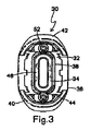
図1−4では、本発明の工具の好ましい態様であるテーピングナイフは、広く10と命名され、作業用末端14、作業用末端とは反対の柄17(隠されている)およびハンドル末端16を含む。テーピングナイフが好ましい工具であるが、他の手作業用工具例えば掻き取り具も下記の本発明のハンマーを備えることも本発明に含まれる。当業者に周知のように、ブレード12には、種々の幅および形状のものが含まれ、或るものは柄がないが、作業用末端14は、好ましくは、ウォールボード化合物または同様な硬化できる物質を滑らかにするために直線の縁である。これらの工具の使用者にとり重要なことは、もし工具が誤って特に高所例えば梯子から落下したとき、作業用末端14が、縁を損傷するかもしれない地面と衝突しないことである。
1-4, the taping knife, which is a preferred embodiment of the tool of the present invention, is broadly named 10 and has a working
ハンドル18は、好ましくはハンドルおよびブレード12が一体化して結合するようにインサート成形により、ハンドルの末端16へ取り付けられる。しかし、他の結合技術も含まれ、例えばリベットまたはねじ込みの固定具も用いられる。また、ハンドル18には、当業者に周知のように、複数の部分、例えば比較的固いプラスチック内部部分20と比較的弾性があって覆うように成形された取っ手部分22とが設けられる。好適なハンドルの構造は、本明細書で参考として引用される米国特許出願11/187582に示されている。
The
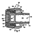
好ましい態様では、ハンドル18は、ブレード末端24そしてブレード末端とは反対のハンマー末端26を有する。ハンマー30は、ハンドル18のハンマー末端26へ取り付けられ、そしてハンドルへ取り付けられるように形成された第1の末端34および衝撃に抵抗するようにデザインされた第2の反対の末端36を有する本体32を有する。好ましい態様では、ハンマー30は、典型的な亜鉛ハンマーと比べたとき、比較的固く軽量であるポリマー性材料から少なくとも一部つくられる。考えられるポリマーはポリカーボネートであるが、もし重量、衝撃抵抗性、成形可能性およびコストで同等であるならば、同様な材料も考えられる。
In a preferred embodiment, the
より詳細には、本体32は、ほぼ軸方向に配置された芯38、および芯から半径方向に芯から離れているが芯へ一体化されて結合しているスカート部40を含む。スカート部40は、ブレード12へ向かってほぼ突き出しており、ハンドル18と係合するように形成された縁44および外部の表面42を有する。
More particularly, the
図2では、芯38は、ブレードへ向かって突き出しそしてスカート部40の縁44を越えて延在する舌状突起部分46を有する。舌状突起部分46は、好ましくは、中空であり、ハンドル18の凹みに受容される。ピン(図示せず)は、ハンマー30をハンドル18へ取り付けるために、ハンドル18および取付け孔48を通る。さらに、芯38が、化学接着剤、超音波溶接、インサート成形などによってハンドル18へ取り付けられることも考えられる。
In FIG. 2, the
本発明のハンマーの特徴は、それがブレード12の反対のハンドル末端16から軸方向へ移動していることである。言い換えれば、ハンドル18は、ブレード12からハンマー30を分離する。軸方向の移動は、ハンマー30が打ち込みに使用されるとき、衝撃力を分散させる。この移動は、ブレード12を保護しそしてまた使用者の手へのショックを和らげる。
A feature of the hammer of the present invention is that it has moved axially from the opposite handle end 16 of the blade 12. In other words, the
図2および4では、ハンマー本体32の第2または衝撃部末端36には、好ましくは、亜鉛であると考えられる金属製キャップ50が設けられる。亜鉛は、固く経済的な金属であり、ウォールボード化合物上に「書く」能力を特徴とするが、固さ、重量およびコストの点で同様な他の金属も考えられる。キャップ50は、好ましくはハンマー30の軸に平行であってキャップ上の対応する任意にねじ切りされた垂下する突起54と係合する、少なくとも1つのねじ切りされた固定具52により本体32へ取り付けられるが、他のタイプの固定具または上記の固定技術も考えられる。
2 and 4, the second or impact
芯38上で、肩部56は、スカート部40上に画成され、そしてキャップが本体32の外部表面42とほぼ同一平面にあるようにキャップ50の輪状の縁58を受容する。キャップ50の中心の突起60は、本体32の凹み62中に受容される(図4)。また、本体32上に含まれるのは、吊り下げ用孔64である。ハンマー30にポリカーボネートのようなポリマー性材料を使用する利点は、吊り下げ用孔64が、ハンマーの構造上の一体性を損なうことなく第2または衝撃部末端36の近くに配置できることである。
On the
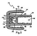
図5では、ハンマー30の別の態様が、広く70と命名される。ハンマー30と70との間で相当するコンポーネントは、同一の符号を付される。ハンマー70の主な明白な特徴は、それがポリマー性材料、ここではポリカーボネートのみからつくられていることである。そのため、金属製キャップ50がないことから、軸方向の芯の部分38は、第2または衝撃部末端36をも形成する共通の厚い衝撃構成部72によりスカート部40は結合される。
In FIG. 5, another aspect of the
ハンマー70の他の違いは、それが吊り下げ用孔64と隣接している複数の壁状物(castellation)74を含むことである。壁状物74は、好ましくは、ハンマー70と一体になって形成され、そしてポリマーのみのハンマー70の成形性を改善する間隔のあいたほぼ軸方向に延在する構成物である。壁状物74が、好ましくは、吊り下げ用孔64へ向かって傾いているかまたは斜切されていることは、理解されるだろう(図5)。壁状物74は、壁状物に隣接して形成された溝76を分離する。壁78は、溝76の近い部分を閉じそしてハンマーの反対の側の対応する溝からそれぞれの溝を分離する。
Another difference of the
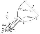
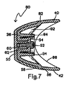
図6および7では、工具10の別の態様が10′と命名され、そして広く80と命名される本発明の別の態様が提供される。今までのハンマーと相当するコンポーネントは、同一の符号が付けられる。ハンマー80は、それが好ましくはポリカーボネートからつくられたポリマー性本体82、および少なくとも1つの固定具52により本体82へ取り付けられたキャップ50を有する点で、ハンマー30と同じである。キャップ50は、好ましくは、上記の理由から亜鉛からつくられる。ハンマー80では、芯84は、スカート部40のほぼ弓状の縁86を通って延在していない。さらに、ハンマー80は、吊り下げ用孔64がない。その代わり、工具10′では、吊り下げ用孔88はハンドル18中にある。
6 and 7, another embodiment of the tool 10 is designated 10 'and another embodiment of the present invention, generally designated 80, is provided. The components corresponding to the conventional hammer are given the same reference numerals.
図8では、本発明のハンマーの別の態様が、広く90と命名される。今までのハンマーと同じコンポーネントは、同一の符号が付けられる。ハンマー90は、全体の形状がハンマー80と同様であるが、金属キャップ50がなくそしてポリマーのみ好ましくはポリカーボネートである点でハンマー70と同様である。そのため、スカート部40および芯38は、共通の厚い衝撃構成部72に沿って結合されている。また、芯82は、スカート部40の縁を通って延在していない。ハンマー30、70および80の場合と同様に、空間92は、スカート部40と芯38、84との間に画成される。ハンマー80の場合と同じく、芯84は、スカート部40の縁86を通って突き出していない。
In FIG. 8, another embodiment of the hammer of the present invention is broadly designated as 90. The same components as the conventional hammer are given the same reference numerals.
ハンマー30、70、80、90を備えた工具10例えばテーピングナイフなどが、従来の金属/ハンマーの工具より比較的軽量であることが分かった。それゆえ、本発明の工具は、操作者に疲労を生じさせることなく、長期間使用するのが容易であり、また使用者または操作者にとり、よりバランスのとれた操作を助ける。
ポリマー性ハンマー付き乾式壁テーピングナイフの特別の態様が示され記述されたが、変化および改変が、広い範囲でそして請求の範囲に規定された本発明から離れることなく、それについてなされることは、当業者により理解されるだろう。
It has been found that a tool 10 with
While a particular embodiment of a dry wall taping knife with a polymeric hammer has been shown and described, changes and modifications may be made thereto without departing from the invention as defined broadly and in the claims that It will be understood by those skilled in the art.
10 テーピングナイフ
10′ テーピングナイフ
12 ブレード
14 作業用末端
16 ハンドル末端
17 柄
18 ハンドル
20 プラスッチク部分
22 取っ手部分
24 ブレード末端
26 ハンマー末端
30 ハンマー
32 本体
34 第1の末端
36 反対の末端
38 芯
40 スカート部
42 外部の表面
44 縁
46 舌状突起
48 取付孔
50 金属性キャップ
52 固定具
54 突起
58 輪状の縁
60 中心の突起
62 凹み
64 吊り下げ用孔
70 ハンマー
72 衝撃構成部
74 壁状物
76 溝
80 ハンマー
82 本体
88 吊り下げ用孔
90 ハンマー
92 空間
DESCRIPTION OF SYMBOLS 10 Taping knife 10 'Taping knife 12
Claims (19)
該ハンドル末端へ取り付けられ、ブレード末端およびハンマー末端を有するハンドル;
該ハンマー末端へ取り付けられ、比較的固い軽量のポリマー性材料からつくられた本体を有するハンマー
からなることを特徴とする工具。 A blade having a working end and a handle end opposite the working end;
A handle attached to the handle end and having a blade end and a hammer end;
A tool comprising a hammer attached to the hammer end and having a body made of a relatively hard, lightweight polymeric material.
該ハンドル末端へ取り付けられ、ブレード末端およびハンマー末端を有するハンドル;
該ハンマー末端へ取り付けられ、そしてハンドルへ取り付けられる形状を有しポリカーボネートからつくられたハンマー部分を含む本体を有するハンマー;
共通の末端から突き出し肩部を画成するスカート部をもつ軸方向の芯を有する該ハンマー本体;
該ハンマー本体へ固定する形状を有し、さらに該肩と係合する縁を有し、組み立てたとき、該本体の外部の表面とほぼ同一平面にある金属性キャップ
からなることを特徴とする工具。 A blade having a working end and a handle end opposite the working end;
A handle attached to the handle end and having a blade end and a hammer end;
A hammer having a body attached to the hammer end and including a hammer portion made of polycarbonate having a shape that is attached to the handle;
The hammer body having an axial core with a skirt projecting from a common end and defining a shoulder;
A tool having a shape to be fixed to the hammer body, further comprising an edge for engaging with the shoulder, and comprising a metallic cap that is substantially flush with the outer surface of the body when assembled. .
該ハンマー本体へ固定される形状をもち、該肩部と係合する縁を有し、組み立てたとき、該本体の外部の表面とほぼ同一平面にある金属性キャップ;および
該本体中の凹みと係合する中心の突起を有する該キャップ
からなることを特徴とするハンドルを有する工具のためのハンマー。 A hammer body defining a generally axial core and a skirt protruding from a common end and defining a shoulder;
A metal cap that is shaped to be secured to the hammer body, has an edge that engages the shoulder, and is substantially flush with the exterior surface of the body when assembled; and a recess in the body; A hammer for a tool having a handle, characterized in that it comprises a cap with a central projection to engage.
Applications Claiming Priority (2)
| Application Number | Priority Date | Filing Date | Title |
|---|---|---|---|
| US11/510,452 US7587778B2 (en) | 2006-08-25 | 2006-08-25 | Wallboard taping knife with polymeric hammer |
| PCT/US2007/017183 WO2008027149A2 (en) | 2006-08-25 | 2007-08-01 | Wallboard taping knife with polymeric hammer |
Publications (2)
| Publication Number | Publication Date |
|---|---|
| JP2010501364A true JP2010501364A (en) | 2010-01-21 |
| JP2010501364A5 JP2010501364A5 (en) | 2010-09-02 |
Family
ID=39111977
Family Applications (1)
| Application Number | Title | Priority Date | Filing Date |
|---|---|---|---|
| JP2009525546A Pending JP2010501364A (en) | 2006-08-25 | 2007-08-01 | Wallboard taping knife with polymer hammer |
Country Status (22)
| Country | Link |
|---|---|
| US (2) | US7587778B2 (en) |
| EP (1) | EP2069108A4 (en) |
| JP (1) | JP2010501364A (en) |
| KR (1) | KR20090048475A (en) |
| CN (1) | CN101505923B (en) |
| AR (1) | AR062532A1 (en) |
| AU (1) | AU2007290810A1 (en) |
| BR (1) | BRPI0714638A2 (en) |
| CA (1) | CA2661717C (en) |
| CO (1) | CO6251298A2 (en) |
| CR (1) | CR10631A (en) |
| GT (1) | GT200900042A (en) |
| HR (1) | HRP20090118A2 (en) |
| IL (1) | IL197228A0 (en) |
| MX (1) | MX2009002070A (en) |
| MY (1) | MY146359A (en) |
| NO (1) | NO20091189L (en) |
| PE (1) | PE20080864A1 (en) |
| RU (1) | RU2009106230A (en) |
| TW (1) | TW200817562A (en) |
| WO (1) | WO2008027149A2 (en) |
| ZA (1) | ZA200901343B (en) |
Cited By (1)
| Publication number | Priority date | Publication date | Assignee | Title |
|---|---|---|---|---|
| KR102566975B1 (en) * | 2022-05-20 | 2023-08-14 | 강태호 | Multifunctional putty hera |
Families Citing this family (18)
| Publication number | Priority date | Publication date | Assignee | Title |
|---|---|---|---|---|
| US8060962B2 (en) * | 2009-09-05 | 2011-11-22 | David Shortt | Taping knife with hammer |
| US8819944B2 (en) * | 2010-06-07 | 2014-09-02 | Hyde Tools, Inc. | Bladed tool with a bent blade-retaining shank |
| USD742199S1 (en) * | 2014-06-27 | 2015-11-03 | A. Richard Tools Co. | Taping knife |
| CN105983954A (en) * | 2015-02-06 | 2016-10-05 | 杭州巨星工具有限公司 | Hand tool with reliable connection |
| US10518401B2 (en) | 2015-02-06 | 2019-12-31 | Hangzhou Great Star Tools Co., Ltd. | Hand tool with reliable connections |
| AU2017217377B2 (en) | 2016-02-08 | 2019-06-27 | Swimc Llc | Folding tool |
| USD808242S1 (en) | 2016-02-08 | 2018-01-23 | The Sherwin-Williams Company | Prep tool |
| USD809359S1 (en) | 2016-02-08 | 2018-02-06 | The Sherwin-Williams Company | Folding tool |
| USD808241S1 (en) | 2016-02-08 | 2018-01-23 | The Sherwin-Williams Company | Prep tool |
| CN106312941B (en) * | 2016-11-04 | 2018-09-11 | 杭州中杰工具有限公司 | A kind of preparation method of high productivity combinatorial disjunctor chisel |
| USD828740S1 (en) | 2017-01-17 | 2018-09-18 | The Sherwin-Williams Company | Multi-tool with bit slot |
| NL1042591B1 (en) * | 2017-10-16 | 2019-04-24 | Magali Shachar | Cleft-Mallet |
| TWD193891S (en) | 2018-02-09 | 2018-11-11 | 日商七十八股份有限公司 | Replacement blade for hand scraper |
| TWD193890S (en) | 2018-02-09 | 2018-11-11 | 日商七十八股份有限公司 | Hand scraper |
| GB2586508A (en) * | 2019-08-23 | 2021-02-24 | Scot Young Res Limited | Mop head and a method of making the same |
| USD934044S1 (en) * | 2019-08-27 | 2021-10-26 | Phaanix Pty Ltd | Drywall taping blade |
| CN111973063B (en) * | 2020-07-10 | 2021-07-20 | 湖南工程学院 | Floor furniture waxing device |
| CN115445876A (en) * | 2022-10-13 | 2022-12-09 | 威海速诺户外用品有限公司 | Handheld vibrations moulding sword |
Citations (5)
| Publication number | Priority date | Publication date | Assignee | Title |
|---|---|---|---|---|
| JPS60146680U (en) * | 1984-03-07 | 1985-09-28 | 大野 哲平 | Dual use hammer |
| JPS619275U (en) * | 1984-06-23 | 1986-01-20 | 株式会社 前田シエルサ−ビス | shotcress hammer |
| JPS63176088U (en) * | 1986-11-29 | 1988-11-15 | ||
| JP3105526U (en) * | 2004-05-27 | 2004-11-18 | 仁士 菊池 | Universal tool |
| JP2005510374A (en) * | 2001-11-21 | 2005-04-21 | スナップ − オン テクノロジーズ,インコーポレイテッド | Encapsulated dead blow hammer with improved skeleton |
Family Cites Families (24)
| Publication number | Priority date | Publication date | Assignee | Title |
|---|---|---|---|---|
| US979058A (en) * | 1909-12-08 | 1910-12-20 | Ramon Bove | Hair-waving machine. |
| US1557853A (en) * | 1925-04-07 | 1925-10-20 | W C Lipscomb | Tool handle |
| US1779293A (en) * | 1928-02-25 | 1930-10-21 | J O Thompson | Painter's implement |
| US3343576A (en) * | 1965-12-20 | 1967-09-26 | Vaughan & Bushnell Mfg Co | Dead-blow hammer head |
| GB1196481A (en) * | 1967-02-21 | 1970-06-24 | Thor Hammer Company Ltd | Improvements in Hammers |
| US3562826A (en) * | 1968-11-29 | 1971-02-16 | James P Vaughn | Multipurpose scraping tool |
| US4620369A (en) * | 1984-08-09 | 1986-11-04 | Gercken Richard H | Drywall knife |
| DE3525163A1 (en) * | 1985-07-13 | 1987-01-22 | Werner Hermann Wera Werke | TOOL HANDLE, ESPECIALLY FOR SCREWDRIVERS |
| US5327612A (en) * | 1993-03-02 | 1994-07-12 | Marshalltown Trowel Company | Plastic molded trowel handle having fingerguard and palm grip |
| US5372053A (en) * | 1993-12-02 | 1994-12-13 | Lee; Chang C. | Hammer |
| US5615445A (en) * | 1994-12-27 | 1997-04-01 | Marshalltown Trowel Company | Taping knife handle |
| US5546625A (en) * | 1995-07-13 | 1996-08-20 | Mealey, Sr.; Eddie H. | Multipurpose painter's tool |
| US5976799A (en) * | 1996-03-21 | 1999-11-02 | The Board Of Trustees Of The University Of Arkansas | Early detection of ovarian carcinoma using P16 gene products |
| US5956788A (en) * | 1997-07-23 | 1999-09-28 | Warner Manufacturing Company | Ergonomic, single hand, folding painter's tool |
| US5956799A (en) * | 1997-09-10 | 1999-09-28 | Panaccione; Mark Thomas | Putty knife and scraper handle |
| US5979058A (en) | 1998-06-10 | 1999-11-09 | Warner Manufacturing Company | Contractor hand tool |
| US6131290A (en) * | 1999-03-30 | 2000-10-17 | Ding Wei Enterprises, Inc. | Mason's hand tool |
| FR2791591A1 (en) * | 1999-04-02 | 2000-10-06 | Outil Parfait Km Ets Marquardt | Bi-material handle for tool for plasterer or painter has interchangeable endpieces made of metal or plastic such as to differentiate quality of similar tools |
| US6182317B1 (en) * | 1999-05-10 | 2001-02-06 | Chin-Chen Huang | Scraper having hammering head connected with the blade |
| US6272708B1 (en) * | 2000-03-14 | 2001-08-14 | Martin Chen | Scraper kit for masons |
| US6421860B1 (en) * | 2000-08-11 | 2002-07-23 | Phillip G. Abbott | Painter's tool |
| US6530098B1 (en) * | 2000-08-11 | 2003-03-11 | Allway Tools, Inc. | Multiple tool device |
| US6860180B1 (en) * | 2003-10-31 | 2005-03-01 | Chien-Hsia Liao | Screwdriver provided with percussion mechanism to facilitate the unfastening and the fastening of screw |
| US7434318B2 (en) * | 2005-07-22 | 2008-10-14 | United States Gypsum Company | Tool with enlarged hammer element |
-
2006
- 2006-08-25 US US11/510,452 patent/US7587778B2/en active Active
-
2007
- 2007-08-01 AU AU2007290810A patent/AU2007290810A1/en not_active Abandoned
- 2007-08-01 KR KR1020097003952A patent/KR20090048475A/en not_active Application Discontinuation
- 2007-08-01 RU RU2009106230/02A patent/RU2009106230A/en not_active Application Discontinuation
- 2007-08-01 MY MYPI20090767A patent/MY146359A/en unknown
- 2007-08-01 WO PCT/US2007/017183 patent/WO2008027149A2/en active Application Filing
- 2007-08-01 JP JP2009525546A patent/JP2010501364A/en active Pending
- 2007-08-01 MX MX2009002070A patent/MX2009002070A/en active IP Right Grant
- 2007-08-01 BR BRPI0714638-8A patent/BRPI0714638A2/en not_active IP Right Cessation
- 2007-08-01 CA CA2661717A patent/CA2661717C/en active Active
- 2007-08-01 EP EP07810984A patent/EP2069108A4/en not_active Withdrawn
- 2007-08-01 CN CN2007800315921A patent/CN101505923B/en active Active
- 2007-08-20 PE PE2007001120A patent/PE20080864A1/en not_active Application Discontinuation
- 2007-08-24 TW TW096131539A patent/TW200817562A/en unknown
- 2007-08-24 AR ARP070103781A patent/AR062532A1/en unknown
-
2009
- 2009-02-24 HR HR20090118A patent/HRP20090118A2/en not_active Application Discontinuation
- 2009-02-24 IL IL197228A patent/IL197228A0/en unknown
- 2009-02-24 GT GT200900042A patent/GT200900042A/en unknown
- 2009-02-25 ZA ZA200901343A patent/ZA200901343B/en unknown
- 2009-02-25 CR CR10631A patent/CR10631A/en not_active Application Discontinuation
- 2009-02-25 CO CO09019186A patent/CO6251298A2/en not_active Application Discontinuation
- 2009-03-20 NO NO20091189A patent/NO20091189L/en not_active Application Discontinuation
- 2009-08-07 US US12/537,574 patent/US20090293200A1/en not_active Abandoned
Patent Citations (5)
| Publication number | Priority date | Publication date | Assignee | Title |
|---|---|---|---|---|
| JPS60146680U (en) * | 1984-03-07 | 1985-09-28 | 大野 哲平 | Dual use hammer |
| JPS619275U (en) * | 1984-06-23 | 1986-01-20 | 株式会社 前田シエルサ−ビス | shotcress hammer |
| JPS63176088U (en) * | 1986-11-29 | 1988-11-15 | ||
| JP2005510374A (en) * | 2001-11-21 | 2005-04-21 | スナップ − オン テクノロジーズ,インコーポレイテッド | Encapsulated dead blow hammer with improved skeleton |
| JP3105526U (en) * | 2004-05-27 | 2004-11-18 | 仁士 菊池 | Universal tool |
Cited By (1)
| Publication number | Priority date | Publication date | Assignee | Title |
|---|---|---|---|---|
| KR102566975B1 (en) * | 2022-05-20 | 2023-08-14 | 강태호 | Multifunctional putty hera |
Also Published As
| Publication number | Publication date |
|---|---|
| ZA200901343B (en) | 2010-07-28 |
| CA2661717A1 (en) | 2008-03-06 |
| MX2009002070A (en) | 2009-03-09 |
| US20090293200A1 (en) | 2009-12-03 |
| NO20091189L (en) | 2009-03-20 |
| WO2008027149A3 (en) | 2008-10-02 |
| BRPI0714638A2 (en) | 2013-07-16 |
| WO2008027149A2 (en) | 2008-03-06 |
| RU2009106230A (en) | 2010-09-27 |
| CR10631A (en) | 2009-06-05 |
| TW200817562A (en) | 2008-04-16 |
| EP2069108A2 (en) | 2009-06-17 |
| HRP20090118A2 (en) | 2009-05-31 |
| KR20090048475A (en) | 2009-05-13 |
| PE20080864A1 (en) | 2008-08-23 |
| EP2069108A4 (en) | 2011-09-07 |
| CN101505923A (en) | 2009-08-12 |
| AR062532A1 (en) | 2008-11-12 |
| US7587778B2 (en) | 2009-09-15 |
| CO6251298A2 (en) | 2011-02-21 |
| CN101505923B (en) | 2011-07-20 |
| MY146359A (en) | 2012-08-15 |
| CA2661717C (en) | 2013-04-23 |
| GT200900042A (en) | 2011-07-28 |
| AU2007290810A1 (en) | 2008-03-06 |
| US20080047074A1 (en) | 2008-02-28 |
| IL197228A0 (en) | 2009-12-24 |
Similar Documents
| Publication | Publication Date | Title |
|---|---|---|
| JP2010501364A (en) | Wallboard taping knife with polymer hammer | |
| US7434318B2 (en) | Tool with enlarged hammer element | |
| RU2417292C2 (en) | Handle of palette knife with identification insert | |
| RU2673264C2 (en) | Vibration reduction mechanism for striking tool | |
| JP3116035U (en) | bucket | |
| CA2830632C (en) | Handle protector for a hand tool | |
| CA2615766A1 (en) | Taping knife with offset handle | |
| JP2010501364A5 (en) | ||
| WO2016022594A1 (en) | Hammer | |
| US6158307A (en) | Shock absorption system for a striking tool | |
| US6497439B1 (en) | Snow shovel having light weight and greater strength | |
| US5906144A (en) | Toe-nailing hammer | |
| JP6921278B2 (en) | Hollow golf club head | |
| KR100528699B1 (en) | Hammer having a function | |
| US20040149086A1 (en) | Attachment for a tool | |
| JP6722563B2 (en) | Hollow golf club head | |
| US9566703B2 (en) | Hand tool with handle apparatus and associated method |
Legal Events
| Date | Code | Title | Description |
|---|---|---|---|
| A521 | Request for written amendment filed |
Free format text: JAPANESE INTERMEDIATE CODE: A523 Effective date: 20100713 |
|
| A621 | Written request for application examination |
Free format text: JAPANESE INTERMEDIATE CODE: A621 Effective date: 20100713 |
|
| RD03 | Notification of appointment of power of attorney |
Free format text: JAPANESE INTERMEDIATE CODE: A7423 Effective date: 20111216 |
|
| A131 | Notification of reasons for refusal |
Free format text: JAPANESE INTERMEDIATE CODE: A131 Effective date: 20120821 |
|
| A977 | Report on retrieval |
Free format text: JAPANESE INTERMEDIATE CODE: A971007 Effective date: 20120823 |
|
| A02 | Decision of refusal |
Free format text: JAPANESE INTERMEDIATE CODE: A02 Effective date: 20130205 |