JP2010501336A - Fluid assembly comprising a purification element - Google Patents
Fluid assembly comprising a purification element Download PDFInfo
- Publication number
- JP2010501336A JP2010501336A JP2009525704A JP2009525704A JP2010501336A JP 2010501336 A JP2010501336 A JP 2010501336A JP 2009525704 A JP2009525704 A JP 2009525704A JP 2009525704 A JP2009525704 A JP 2009525704A JP 2010501336 A JP2010501336 A JP 2010501336A
- Authority
- JP
- Japan
- Prior art keywords
- fluid
- substrate
- block
- handling device
- purifier
- Prior art date
- Legal status (The legal status is an assumption and is not a legal conclusion. Google has not performed a legal analysis and makes no representation as to the accuracy of the status listed.)
- Pending
Links
Images

Classifications
-
- B—PERFORMING OPERATIONS; TRANSPORTING
- B01—PHYSICAL OR CHEMICAL PROCESSES OR APPARATUS IN GENERAL
- B01D—SEPARATION
- B01D53/00—Separation of gases or vapours; Recovering vapours of volatile solvents from gases; Chemical or biological purification of waste gases, e.g. engine exhaust gases, smoke, fumes, flue gases, aerosols
- B01D53/34—Chemical or biological purification of waste gases
- B01D53/74—General processes for purification of waste gases; Apparatus or devices specially adapted therefor
-
- B—PERFORMING OPERATIONS; TRANSPORTING
- B01—PHYSICAL OR CHEMICAL PROCESSES OR APPARATUS IN GENERAL
- B01D—SEPARATION
- B01D2258/00—Sources of waste gases
- B01D2258/02—Other waste gases
- B01D2258/0216—Other waste gases from CVD treatment or semi-conductor manufacturing
Landscapes
- Engineering & Computer Science (AREA)
- Chemical & Material Sciences (AREA)
- Environmental & Geological Engineering (AREA)
- Analytical Chemistry (AREA)
- General Chemical & Material Sciences (AREA)
- Oil, Petroleum & Natural Gas (AREA)
- Chemical Kinetics & Catalysis (AREA)
- Health & Medical Sciences (AREA)
- Biomedical Technology (AREA)
- Separation Using Semi-Permeable Membranes (AREA)
- Filtering Of Dispersed Particles In Gases (AREA)
Abstract
本発明は、ポートを有する流体操作デバイス(11)と、流体導管を有する基板(12)と、ブロック浄化器(13)とを含む流体アセンブリに関する。ブロック浄化器は、流路(14)を1つしか含まず、この流路に浄化要素(15)が配置される。ブロック浄化器は、流体操作デバイスと基板との間に位置付けられ、ブロック浄化器の流路は、流体操作デバイスのポートおよび基板の流体導管と流体的に連通状態にある。
【選択図】 図1
The present invention relates to a fluid assembly comprising a fluid handling device (11) having a port, a substrate (12) having a fluid conduit, and a block purifier (13). The block purifier includes only one flow path (14), and the purification element (15) is disposed in this flow path. The block purifier is positioned between the fluid handling device and the substrate, and the flow path of the block purifier is in fluid communication with the port of the fluid handling device and the fluid conduit of the substrate.
[Selection] Figure 1
Description
本発明は、流体アセンブリに関する。特に、本発明は、流体、例えば、半導体の製造に使用されるガスを含むガスなどの流体を浄化するために使用される流体アセンブリに関する。固体、コロイド、ゲル、および液体粒子などの粒状物質と、均質または分子汚染物質などの化学物質を除去するために、産業プロセスにおいて使用するガスが浄化されてもよい。半導体の製造においては、ガス中の粒状物質により製造中の半導体に傷が付く可能性があるため、例えば、粒状物質を除去するために、ガスが浄化されてもよい。 The present invention relates to fluid assemblies. In particular, the present invention relates to fluid assemblies used to purify fluids, such as gases including gases used in semiconductor manufacturing. Gases used in industrial processes may be purified to remove particulates such as solids, colloids, gels, and liquid particles and chemicals such as homogeneous or molecular contaminants. In the manufacture of semiconductors, there is a possibility that the semiconductor being manufactured may be damaged by the particulate matter in the gas. For example, the gas may be purified in order to remove the particulate matter.
本発明により、高効率で高信頼性の流体アセンブリが提供される。本発明の1つの態様によれば、流体アセンブリは、流体操作デバイスと、基板と、ブロック浄化器とを含んでもよい。流体操作デバイスは、例えば、マスフローコントローラ、温度センサ、圧力センサ、または流体が流入および/または貫流する任意の他のデバイスを含む、流体とともに使用する任意のタイプのデバイスであってもよい。流体操作デバイスは、少なくとも1つのポートを含んでもよい。基板は、1つ以上の流体導管を有し、1つ以上の流体操作デバイスを支持する任意の本体であってもよい。ブロック浄化器は、流体操作デバイスと基板との間に位置してもよく、流体操作デバイスのポートと基板の流体導管との間を連通状態にする唯一の流路を含んでもよい。ブロック浄化器は、流路に配置された透過性浄化要素をさらに含んでもよい。基板の流体導管と流体操作デバイスのポートとの間に流れる流体が、ブロック浄化器の流路を通過し、浄化要素によって浄化される。 The present invention provides a highly efficient and reliable fluid assembly. According to one aspect of the invention, the fluid assembly may include a fluid handling device, a substrate, and a block purifier. The fluid handling device may be any type of device for use with fluids, including, for example, a mass flow controller, temperature sensor, pressure sensor, or any other device through which fluid flows in and / or through. The fluid handling device may include at least one port. The substrate may be any body having one or more fluid conduits and supporting one or more fluid handling devices. The block purifier may be located between the fluid handling device and the substrate and may include a single flow path that provides communication between the port of the fluid handling device and the fluid conduit of the substrate. The block purifier may further include a permeable purification element disposed in the flow path. Fluid flowing between the substrate fluid conduit and the port of the fluid handling device passes through the flow path of the block purifier and is purified by the purification element.
本発明の流体アセンブリには、多くの利点がある。例えば、本発明の流体アセンブリには、シールがほとんどない。ブロック浄化器が、単一の流路しか含まなくてもよいため、流路がブロック浄化器に出入りする場所にだけシールを設置することができ、高度に洩れ耐性のある流体アセンブリが得られる。流路が1つしかない別の利点は、ブロック浄化器のサイズが小型でコンパクトになることで、流体アセンブリのサイズが小さくなり、全体として流体アセンブリの機械的完全性を維持しながら、ブロック浄化器の利用目的がより幅広くなることである。 The fluid assembly of the present invention has many advantages. For example, the fluid assembly of the present invention has few seals. Since the block purifier need only contain a single flow path, a seal can be installed only where the flow path enters and exits the block purifier, resulting in a highly leak-resistant fluid assembly. Another advantage of having only one flow path is that the size of the block purifier is small and compact, which reduces the size of the fluid assembly and maintains the mechanical integrity of the fluid assembly as a whole, while purifying the block. The purpose of use of the vessel is to be wider.
いくつかの実施形態において、流体アセンブリが、流体操作デバイスと基板との間に位置するスペーサーをさらに含んでもよく、このスペーサーは、ブロック浄化器から離れた位置にある別個のものである。例えば、ブロック浄化器は、流体操作デバイスの第1のポート、例えば、入口ポートと、基板の第1の流体導管と流体連通状態にあってもよい。流体操作デバイスは、第2のポート、例えば、出口ポートを含んでもよく、基板は、第2の流体導管を含んでもよい。スペーサーは、流体操作デバイスと基板との間に位置されてもよく、流体操作デバイスの第2のポートと、基板の第2の流体導管との間とを流体連通状態にする流路を含んでもよい。好ましくは、スペーサーは、ブロック浄化器の厚みに対応する厚みを有してもよい。 In some embodiments, the fluid assembly may further include a spacer located between the fluid handling device and the substrate, the spacer being separate from the block purifier. For example, the block purifier may be in fluid communication with a first port of the fluid handling device, eg, an inlet port, and a first fluid conduit of the substrate. The fluid handling device may include a second port, eg, an outlet port, and the substrate may include a second fluid conduit. The spacer may be positioned between the fluid handling device and the substrate and may include a flow path that provides fluid communication between the second port of the fluid handling device and the second fluid conduit of the substrate. Good. Preferably, the spacer may have a thickness corresponding to the thickness of the block purifier.
他の実施形態において、流体操作デバイスが、脚部を有するものであってもよい。例えば、流体操作デバイスは、基部を含んでもよい。ブロック浄化器は、流体操作デバイスの基部の1つの領域と基板との間に位置されてもよい。ブロック浄化器は、流体操作デバイスの第1のポート、例えば、入口ポートと、基板の第1の流体導管との間が流体連通状態にあってもよい。流体操作デバイスは、第2のポート、例えば、出口ポートを含んでもよく、基板は、第2の流体導管を含んでもよい。基部の別の領域で、流体操作デバイスは、基板に伸長する脚部を含んでもよい。脚部は、基板の第2の流体導管と直接的に流体連通状態にあってもよい流体操作デバイスの第2のポートを含んでもよい。 In other embodiments, the fluid handling device may have legs. For example, the fluid handling device may include a base. The block purifier may be located between one region of the base of the fluid handling device and the substrate. The block purifier may be in fluid communication between a first port of the fluid handling device, eg, an inlet port, and the first fluid conduit of the substrate. The fluid handling device may include a second port, eg, an outlet port, and the substrate may include a second fluid conduit. In another region of the base, the fluid handling device may include legs that extend to the substrate. The legs may include a second port of the fluid handling device that may be in direct fluid communication with the second fluid conduit of the substrate.
本発明の他の実施形態に関して、流体操作デバイスおよび/または基板は、切欠きを含んでもよく、ブロック浄化器は、切欠きに配置されてもよい。切欠きは、ブロック浄化器に空間を与えることで、基板上に流体操作デバイスを直接取り付けられるようになることによって、空間要件が低減し、よりコンパクトな流体アセンブリを提供できる。 With respect to other embodiments of the present invention, the fluid handling device and / or the substrate may include a notch and the block purifier may be disposed in the notch. The notch provides space for the block clarifier so that the fluid handling device can be mounted directly on the substrate, thereby reducing space requirements and providing a more compact fluid assembly.
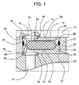
本発明を具現化した流体アセンブリは、種々のやり方で構成されてもよい。図1および図2に、流体アセンブリ10の多くの例の1つが示されており、同図において、流体アセンブリは、流体操作デバイス11、基板12、およびブロック浄化器13を含む。図1および図2に示す流体アセンブリ10のブロック浄化器13は、1つのみの流路14と、流路14に配置された浄化要素15とを含んでもよい。流路14は、浄化要素15を通りながら、ブロック浄化器13を通って伸長してもよく、流体操作デバイス11の1つのみのポート16と、基板12の1つのみの流体導管17と流体連通状態にあってもよい。
A fluid assembly embodying the present invention may be configured in various ways. FIGS. 1 and 2 show one of many examples of a
ブロック浄化器は、円筒状、ディスク状、または直方体状などの不規則形状または規則形状を含む任意の適切な形状のものであってもよく、多種多様な方法で構成されてもよい。例えば、ブロック浄化器は、Palermoらの米国特許第6,514,323号明細書に開示されたものと同様の方法で構成されてもよい。代替的には、ブロック浄化器は、発明者としてBrian Palermoが名を連ねる、2006年8月25日に出願された“Purification Assemblies,Purification Units,and Methods of Assembling Purification Assemblies”という発明の名称の米国仮特許出願第60/840,024号明細書に開示されたものと同様の方法で構成されてもよい。米国特許第6,514,323号明細書および米国仮特許出願第60/840,024号明細書は共に、ブロック浄化器の特徴をさらにサポートするために、本願明細書に参照により組み込まれる。 The block purifier may be of any suitable shape including irregular or regular shapes, such as cylindrical, disk, or cuboid, and may be configured in a wide variety of ways. For example, the block purifier may be configured in a manner similar to that disclosed in US Pat. No. 6,514,323 to Pallermo et al. Alternatively, the block purifier is named “Purification Assemblies, Purification Units, and Methods of Assembling Purification Inventive United States”, filed on August 25, 2006, invented by Brian Pallemo as the inventor. You may comprise by the method similar to what was indicated by provisional patent application 60 / 840,024 specification. US Pat. No. 6,514,323 and US Provisional Patent Application No. 60 / 840,024 are both incorporated herein by reference to further support the features of the block purifier.
ブロック浄化器13は、1つ以上の取り付け面、例えば、対向する取り付け面18、19を含んでもよい。流体操作デバイス11と基板12との間に、ブロック浄化器13が据え付けられると、取り付け面の一方18が、流体操作デバイス11の対応する取り付け面と対面し接触してもよく、別の取り付け面19が、基板12の別の対応する取り付け面と対面し接触してもよい。図1に示す実施形態において、ブロック浄化器13は、ブロック浄化器13の両側にある2つの実質的に平坦な取り付け面18、19を含み、唯一の流路14は、各取り付け面18、19に開口する。ブロック浄化器13は、例えば、ブロック部材にあるボルト孔のボルト締め、溶接、または、締まり嵌めを含む任意の適切な方法で、流体操作デバイス11および/または基板12に永続的または脱着可能に取り付けられてもよい。
The
唯一の流路14は、ブロック浄化器の取り付け面18、19間に伸長してもよく、例えば、流体操作デバイス11の入口ポート16と、基板12の流体導管17との間に流体連通状態をもたらす。このため、流路14は、流体操作デバイス11と対面する取り付け面18と、基板12と対面する取り付け面19との間に伸長してもよい。一般に、流路は、種々に構成されてもよい。流路は、例えば、直線形の構成またはL字状の構成などの任意の適切な構成を有してもよく、円形の構成など、任意の断面構成を有してもよい。また、流路は、ブロック浄化器の両側にある開口が同軸になる状態でブロック浄化器を直線的に通過するものであってもよく、あるいは、代替的には、ブロック浄化器の両側にある開口が同軸ではない状態にオフセットされてもよい。取り付け面の流路開口は、基板および流体操作デバイスの開口に適合するように標準化されてもよい。
A
ブロック浄化器は、唯一の流路を有するブロック部材と、流路にある浄化要素とを備えてもよい。ブロック部材は、円筒状、ディスク状、または直方体状などの不規則形状または規則形状を含む任意の適切な形状のものであってもよく、種々に構成されてもよい。例えば、ブロック部材は、単一の一体的または統合的なブロック部材を備えてもよく、またはブロック部材を形成するために互いに取り付け可能な複数の部品を備えてもよい。ブロック部材が、互いに取り付け可能な2つ以上の部品を備える場合、これらの部品は、互いに永続的に固定されても、脱着可能に取り付けられてもよい。例えば、部品は、互いに対して、溶接、ボルト締め、螺装、または締まり嵌めされてもよい。ブロック部材は、浄化要素が配置される空隙を有してもよく、浄化要素が配置される空隙を通って、唯一の流路が伸長する。 The block purifier may comprise a block member having a single flow path and a purification element in the flow path. The block member may have any suitable shape including irregular shapes or regular shapes such as a cylindrical shape, a disk shape, or a rectangular parallelepiped shape, and may be variously configured. For example, the block member may comprise a single integral or integral block member or may comprise a plurality of parts that can be attached together to form the block member. If the block member comprises two or more parts that can be attached to each other, these parts may be permanently fixed to each other or detachably attached. For example, the parts may be welded, bolted, screwed, or interference fitted to each other. The blocking member may have a void in which the purification element is disposed, and a unique flow path extends through the void in which the purification element is disposed.
代替的には、ブロック浄化器13は、ブロック部材21と、取り付け具22とを備えてもよい。ブロック部材21は、ソケット23を含んでもよく、取り付け具22は、ブロック部材21のソケット23に装着されてもよい。いくつかの実施形態において、ブロック部材21は、なんら流路を有さなくてもよい。取り付け具22は、浄化要素15が配置されてもよい空隙24を含んでもよく、ブロック浄化器13の唯一の流路14が、取り付け具22を通って伸長し、空隙24を含んでもよい。取り付け具22は、円筒状、ディスク状、または直方体状の構成などの不規則構成または規則構成を含む任意の適切な構成のものであってもよい。取り付け具22は、単一の一体的または統合的な取り付け具を備えてもよく、または取り付け具22を形成するために互いに取り付け可能な複数の部品25、26を備えてもよい。図1に示す2つの部品25、26の構成は、同様のものであるが、例えば、異なる形状および/または異なる寸法、例えば、異なる厚みなどの様々な構成を有するものであってもよい。取り付け具が、互いに取り付け可能な2つ以上の部品を備える場合、これらの部品は、例えば、溶接、または脱着可能な取り付け、例えば、ボルト締めによって、互いに永続的に固定されてもよい。例示した実施形態において、2つの部品25、26は、溶接部27によって永続的に取り付けられてもよい。
Alternatively, the
図1に示す取り付け具22は、互いに取り付け可能な2つの部品25、26を含み、浄化要素15を収容する空隙24を画定する。唯一の流路14は、空隙24を含んでもよく、取り付け面18、19に開口する流路14の開口は、空隙24よりも小さくてもよく、例えば、小さな直径を有してもよい。空隙は、ブロック部材あるいは取り付け具のいずれの場合であっても、浄化要素の場合と同様の構成を含む、多種多様な任意の構成を有するものであってもよい。空隙24は、取り付け具22の2つの部品25、26の間の境界に位置する流路14に配置されてもよい。代替的には、空隙は、複数の部品の1つにのみ配置されてもよい。例えば、部品の1つのほぼ全体を、穴を有した取り付け具で構成し、他の部品を取り付け具の穴に差込み可能なプラグとしてもよい。空隙は、穴の底部とプラグの底面とで形成されてもよい。
The
浄化要素は、種々の適切な構成のものを有してもよい。浄化要素は、例えば、円筒状、円錐状、ディスク状、またはドーム状である多孔性本体であってもよい。浄化要素はまた、大量の繊維または粒子床など、より不規則な構成を有してもよい。好ましくは、浄化要素は、ブロック部材または取り付け具の空隙にある流路に配置されるため、流路を通過するガスの相当量、より好ましくは、すべてが、浄化要素を通過する。浄化要素は、溶接、ろう付け、締め付け、圧着など、シールを形成するための任意の適切な方法で、ブロック部材または取り付け具に接合されてもよい。例えば、取り付け具22を形成するために、複数の部品25、26が互いに直接取り付けられる場合、浄化要素15は、部品25、26のみを圧縮して適所に保持されてもよい。例示した実施形態において、浄化要素15は、例えば、空隙24の周囲にある溝28に浄化要素15の縁部を圧縮することによって、取り付け具22の2つの部品25、26の間に締め付けられてもよい。
The purification element may have a variety of suitable configurations. The purification element may be, for example, a porous body that is cylindrical, conical, disc-shaped, or dome-shaped. The purification element may also have a more irregular configuration, such as a large amount of fiber or particle bed. Preferably, the purification element is disposed in a flow path in the gap of the block member or fixture so that a substantial amount of gas passing through the flow path, more preferably all, passes through the purification element. The purification element may be joined to the block member or fixture in any suitable manner for forming a seal, such as welding, brazing, clamping, crimping, and the like. For example, if a plurality of
浄化要素の構造および孔径は、例えば、浄化要素を流れる流体から除去される材料、最大動作温度、および浄化要素を通る所望の流量特性を含むさまざまな要因に従って選択されうる。半導体製造に使用されるガスを浄化するために浄化要素が使用される場合、浄化要素は、ステンレス鋼、ニッケル、またはハステロイ金属などガス放出量の少ない、焼き付け可能な、耐食性材料で形成されることが好ましい。代替的には、浄化要素を高分子膜または繊維質材料などの高分子材料から、またはガラス繊維材料またはセラミック材料から仕上げてもよい。また、米国特許第5,490,868号明細書および同第5,545,242号明細書に、いくつかのタイプの浄化要素が詳細に記載されており、同特許の内容全体は、本発明の上記および他の特徴をサポートするために、本願明細書に参照により組み込まれる。浄化要素はまた、望ましくないガス成分等の化学物質を含む均質または分子汚染物質を流体から除去するために、媒体、例えば、反応媒体を含んでもよい。Brownらの国際公開第0168241号パンフレットには、反応媒体の1つの例が開示されており、その内容全体は、本発明の上記および他の特徴をサポートするために、本願明細書に参照により組み込まれる。 The structure and pore size of the purification element can be selected according to various factors including, for example, the material removed from the fluid flowing through the purification element, the maximum operating temperature, and the desired flow characteristics through the purification element. When purification elements are used to purify gases used in semiconductor manufacturing, the purification elements must be formed of a bakable, corrosion-resistant material that emits less gas, such as stainless steel, nickel, or hastelloy metal. Is preferred. Alternatively, the purification element may be finished from a polymeric material, such as a polymeric membrane or fibrous material, or from a glass fiber material or a ceramic material. Also, U.S. Pat. Nos. 5,490,868 and 5,545,242 describe several types of purification elements in detail, the entire contents of which are incorporated herein by reference. In order to support these and other features, the present specification is hereby incorporated by reference. The purification element may also include a medium, eg, a reaction medium, to remove homogeneous or molecular contaminants, including chemicals such as undesirable gas components, from the fluid. Brown et al., WO 0168241, discloses one example of a reaction medium, the entire contents of which are incorporated herein by reference to support the above and other features of the present invention. It is.
取り付け具22は、任意の多数の方法で、ブロック部材21のソケット23に取り付けられてもよい。取り付け具は、ブロック部材に永続的に固定されても、脱着可能に取り付けられてもよい。例えば、取り付け具は、溶接、ボルト締め、螺装、圧入、スナップ嵌合、または摩擦嵌合によってブロック部材に取り付けられてもよい。取り付け具22は、例えば、取り付け具22の側面にある少なくとも1つの周囲係合表面を含んでもよく、この表面は、ブロック部材21のソケット11の対応する係合表面と接触してもよい。図1に示すように、取り付け具22は、取り付け具の外部の周りに溝31を含んでもよく、この溝により、取り付け具22の側面上に複数の係合表面32、33ができ、この表面は、ブロック部材21のソケット23の1つ以上の係合表面と接触してもよい。取り付け具22の係合表面32、33は、取り付け面18、19の位置から始まり、溝31に対して軸方向に伸長するものであってもよい。係合表面32、33の軸長さは、取り付け具22の全軸長さの約50%未満であってもよく、より好ましくは、35%未満であってもよく、さらに好ましくは、25%未満であってもよい。接触点での面積当たりの力は、係合表面の表面積の低減に伴い増大する。このように、面積当たりの圧力および力が増大すると、エネルギー点が高くなり、ブロック部材21のソケット23における取り付け具22の締まり嵌めが良好な場合がある。さらに、溶接部27は、ブロック部材21と接触せずに溝31内に伸長することで、溶接部27に行われることがある機械加工量が低減することもある。
The
ブロック浄化器21は、例えば、ブロック浄化器13の取り付け面と流体操作デバイス11の対応する取り付け面との間、またはブロック浄化器13の取り付け面と基板12の対応する取り付け面との間の漏出防止のために、1つ以上のシール34を含んでもよい。Cリングシール、Oリングシール、Wシール、またはZシールなどの面シールを含むシールが、流体アセンブリの外部からの流路を封止するために、流路の周りに配置されてもよい。例えば、各取り付け面に位置する流路開口の周りに配置された溝または陥凹内、および流体操作デバイスおよび基板の取り付け面に配置されてもよく、対応する溝または凹部内に、面シールが置かれてもよい。ブロック浄化器が、流体操作デバイスおよび/または基板に取り付けられる場合、シールにより、ブロック浄化器と流体操作デバイスとの間およびブロック浄化器と基板との間の漏出が防止される。
The
ブロック部材および取り付け具を含むブロック浄化器は、ステンレス鋼などの金属材料および高分子材料を含む任意の適切な材料から形成されてもよい。取り付け具の第1および第2の部品などのブロック浄化器の異なる部品は、異なる材料で形成されてもよいが、ブロック浄化器の部品は、同じ材料、ステンレス鋼などの金属から形成されることが好ましい。 The block purifier, including the block member and fixture, may be formed from any suitable material including metallic materials such as stainless steel and polymeric materials. Different parts of the block purifier, such as the first and second parts of the fixture, may be formed of different materials, but the parts of the block purifier should be formed of the same material, metal such as stainless steel Is preferred.
流体操作デバイスは、例えば、マスフローコントローラ、温度センサ、圧力センサ、または流体が流入および/または貫流する任意の他のデバイスを含む、流体とともに使用する任意のタイプのデバイスであってもよい。流体操作デバイスは、1つ以上のポート、例えば、2つのポートを有してもよい。流体操作デバイスは、入口ポートのみを有してもよく、入口ポートおよび出口ポートを有してもよい。流体操作デバイスは、多種多様な方法で構成されてもよい。例えば、流体操作デバイス11は、ブロック浄化器13の取り付け面18とほぼ同一平面上のものであってもよい基部35をさらに含んでもよい。流体操作デバイス11はまた、ブロック浄化器13の取り付け面18と接触する取り付け面36を有してもよい。流体操作デバイス11が基部35を含む場合、流体操作デバイス11の取り付け面36は、基部35上にあってもよい。流体操作デバイス11のポート16が、基部35を通って伸長し、取り付け面36に開口してもよい。
The fluid handling device may be any type of device for use with fluids, including, for example, a mass flow controller, temperature sensor, pressure sensor, or any other device through which fluid flows in and / or through. The fluid handling device may have one or more ports, for example two ports. The fluid handling device may have only an inlet port or may have an inlet port and an outlet port. The fluid handling device may be configured in a wide variety of ways. For example, the
基板は、1つ以上の流体導管を有する任意の本体であってもよい。また、基板は、1つ以上の流体操作デバイスを支持してもよい。基板は、例えば、規則構成または不規則構成を含む任意のさまざまな構成を有してもよい。また、基板12は、ブロック浄化器13の取り付け面19と接触する取り付け面37を有してもよい。取り付け面19、37の両方は、ほぼ同一平面上のものであってもよい。流体導管17が、基板12を通って伸長し、取り付け面37に開口してもよい。
The substrate may be any body having one or more fluid conduits. The substrate may also support one or more fluid handling devices. The substrate may have any of a variety of configurations including, for example, a regular configuration or an irregular configuration. Further, the
図1に示す流体アセンブリ10の実施形態において、ブロック浄化器13は、1つのみの流路14と、流路14に配置された浄化要素15とを含んでもよい。ブロック浄化器13の唯一の流路14は、流体操作デバイス11のポート16、例えば、入口ポートまたは出口ポート、および基板12の流体導管17に対して、整列され封止されてもよい。このように、流路14は、流体操作デバイス11のポート16と、基板12の流体導管17との間で流体連通状態にあってもよく、浄化要素15を通過しながら、ブロック浄化器13を通って伸長してもよい。ブロック浄化器13は、任意の多数の方法で流体操作デバイス11および/または基板12の間に挟まれてもよく、それらに永続的または脱着可能に接続されてもよい。例えば、流体アセンブリの流体操作デバイス11およびブロック浄化器13は、基板12にボルト締めされてもよいが、例えば、溶接または締まり嵌めまたは摩擦嵌合を含む任意の他の固定手段が用いられてもよい。ブロック浄化器は、流体操作デバイスおよび/または基板に脱着可能に接続される場合、流体アセンブリから容易に取り外しが可能である。これにより、使用済みの浄化ユニットを有するブロック浄化器を容易に取り替えることができる。また、これにより、あるブロック浄化器を、異なる媒体を備える浄化要素を含む別のブロック浄化器に置き換えることが可能であることで、多くの異なる方法で流体を浄化するために、流体アセンブリを使用することができる。
In the embodiment of the
いくつかの実施形態において、流体アセンブリは、スペーサーをさらに含んでもよい。例えば、図2は、別個のコンポーネントであり、互いに間隔を置いて設けられてもよいブロック浄化器13とスペーサー40との両方を含む流体アセンブリの実施形態を示す。ブロック浄化器13は、図1に示すブロック浄化器13に類似したものであってもよく、唯一の流路14と、ソケット23を有するブロック部材21と、空隙24を有し、ソケット23に配置された取り付け具22と、空隙24および流路14に配置された浄化要素15とを含んでもよい。ブロック浄化器は、流体操作デバイス11と基板12との間に位置されてもよく、流路14は、基板12の流体導管17と流体操作デバイス11のポート16との間で流体連通状態であってもよい。
In some embodiments, the fluid assembly may further include a spacer. For example, FIG. 2 shows an embodiment of a fluid assembly that includes both a
スペーサーは、例えば、スペースブロックの形状をブロック浄化器の形状に類似したものにするやり方を含む種々のやり方で構成されてもよい。スペースブロックは、ブロック浄化器の厚みに対応する厚みを有してもよく、流体操作デバイスと基板との間に、ブロック浄化器から離れて位置されてもよいことで、ブロック浄化器13の取り付け面18、19を、流体操作デバイス11および基板12の対応する取り付け面36、37に対して平坦にすることができる。
The spacer may be configured in a variety of ways including, for example, making the space block shape similar to the shape of the block purifier. The space block may have a thickness corresponding to the thickness of the block purifier, and may be positioned away from the block purifier between the fluid handling device and the substrate, so that the
スペーサー40は、少なくとも1つの流路41を含んでもよいが、浄化要素を、例えば、流路に含まない。流路41は、スペーサー40を通って伸長してもよく、スペーサー40上、例えば、スペーサー40の両側にある取り付け面42、43で終端してもよい。スペーサー40は、例えば、ブロック浄化器13の場合と同様の方法で、流体操作デバイス11と基板12との間に挟まれ、それらに接続されてもよい。スペーサー40上の取り付け面42、43は、例えば、面シールによって、流体操作デバイス11および基板12上の対応する取り付け面36、37に封止されてもよく、スペーサー40の流路41は、流体操作デバイス11にある第2のポート46、例えば、出口ポートと、基板12にある第2の流体導管47との間で流体的に連通していてもよい。次いで、ブロック浄化器13の唯一の流路14に沿って、基板12の第1の流体導管17から流体が流れてもよく、この場合、流体は、浄化要素15によって浄化されて、流体操作デバイス11の入口ポート16内に流入する。次いで、流体は、浄化されることなく、流体操作デバイス11を通って、流体操作デバイス11の出口ポート46からスペーサー40の流路41に沿って、基板12の第2の流体導管47内に流入してもよい。
The
代替的には、2つの流体操作デバイスを結ぶ基板上に、スペーサーが取り付けられてもよい。例えば、スペーサーの流路は、基板と流体的に連通することなく、流体操作デバイスのポート間で直接連通してもよい。ブロック浄化器を介して、第1の流体操作デバイスを通って第1の流体操作デバイス内に流入した後、流体は、浄化されずに、第1の流体操作デバイスの出口ポートから、スペーサーにある流路を通って、基板へと通じていない第2の流体操作デバイスの入口ポート内へ流入してもよい。 Alternatively, a spacer may be attached on the substrate connecting the two fluid handling devices. For example, the flow path of the spacer may be in direct communication between the ports of the fluid handling device without being in fluid communication with the substrate. After flowing through the block clarifier, through the first fluid handling device and into the first fluid handling device, the fluid is not purified and is in the spacer from the outlet port of the first fluid handling device. It may flow through the flow path into the inlet port of the second fluid handling device that is not in communication with the substrate.
別の形態として、スペーサーは、スペーサーにある任意の流路を有さなくてもよく、例えば、スペーサーは、ソリッドであってもよい。このようなスペーサーは、ポートが1つしかなく、例えば、入口ポートしかない流体操作デバイスに特に有用であろう。 Alternatively, the spacer may not have any channels in the spacer, for example, the spacer may be solid. Such a spacer would be particularly useful for fluid handling devices that have only one port, eg, only an inlet port.
他の実施形態において、流体アセンブリ10は、ブロック浄化器13と、基板12と、脚部50を有する流体操作デバイス11を含んでもよい。例えば、図3に示すように、ブロック浄化器13は、流体操作デバイス11の基部35の1つの領域で、流体操作デバイス11と基板12との間に取り付けられてもよい。流体操作デバイス11の基部35の別の領域が、基板12に伸長する脚部50を含んでもよい。脚部50の高さは、ブロック浄化器13の厚みに対応してもよい。スペーサーが用いられる場合と同様に、流体操作デバイス11の脚部50により、ブロック浄化器13の取り付け面18、19を、流体操作デバイス11と基板12の両方の取り付け面36、37に対して平坦にすることができる。脚部は、任意のポートを含まなくてもよく、例えば、ソリッドであってもよい。しかしながら、例示した実施形態において、脚部50は、基板12にある第2の流体導管47と連通する流体操作デバイス11の第2のポート46、例えば、出口ポートを含んでもよい。流体操作デバイス11の基部35の脚部領域は、例えば、ボルト、溶接、または締まり嵌めによる任意の多数の方法で、基板12に取り付けられてもよく、脚部50の底部は、例えば、面シールによって、基板12上の対応する取り付け面45に封止されてもよい取り付け面51を含んでもよい。次いで、ブロック浄化器13の唯一の流路14に沿って、基板12の第1の流体導管17から流体が流れてもよく、この場合、流体は、浄化要素15によって浄化されて、流体操作デバイス11の入口ポート16内に流入する。次いで、流体は、流体操作デバイス11、脚部50を通って、流体操作デバイス11の出口ポート46から、基板12の第2の流体導管47内に直接流入してもよい。
In other embodiments, the
流体アセンブリの多くの実施形態は、少なくとも2つのポートを有する流体操作デバイスと、ブロック浄化器およびスペーサーまたは流体操作デバイスの脚部を介して流体連通状態になる少なくとも2つの流体導管を有する基板とを含んでもよい。しかしながら、他の実施形態において、流体操作デバイスのポートおよび基板の流体導管は、2つ以上のブロック浄化器を介してすべて流体的に連通状態であってもよく、これらのブロック浄化器には、各々に1つずつしか流路が貫通していない。例えば、図2に示すスペースブロック40または図3に示す脚部50を取り除いてもよく、取り除いた構成部品の代わりに別のブロック浄化器に置き換えられてもよい。図1〜図3に示すブロック浄化器13と同一のものであってもよい第2のブロック浄化器には、流路が1つしかなくてもよい。流路は、浄化要素を含んでもよく、流体操作デバイスの第2のポートと、基板の第2の流体導管との間に封止されてもよい。
Many embodiments of the fluid assembly include a fluid handling device having at least two ports and a substrate having a block purifier and at least two fluid conduits that are in fluid communication through the spacer or the legs of the fluid handling device. May be included. However, in other embodiments, the port of the fluid handling device and the substrate fluid conduit may all be in fluid communication via two or more block purifiers, including: Only one channel passes through each. For example, the
さらなる別の実施形態において、流体アセンブリ10は、流体操作デバイスと、基板と、流体操作デバイスおよび基板の一方または両方にある切欠きに取り付けられたブロック浄化器とを含んでもよい。例えば、図4に示すように、流体操作デバイス11は、基部35を含んでもよく、基部35に、切欠き52が配置されてもよい。図1〜3のブロック浄化器に類似したものであってもよいブロック浄化器13は、切欠き52に永続的または脱着可能に位置されて、流体操作デバイス11のポート16と、基板12の流体導管17との間で流体的に連通状態にあってもよい。切欠き52は、ブロック浄化器13の厚みに対応する深さを有してもよい。次いで、流体操作デバイス11の基部35は、ブロック浄化器13の底部と同一平面上にあることで、ブロック浄化器13および流体操作デバイス11を、基板12上に直接着座させることができる。これにより、スペーサーまたは脚部を使用せずにすむことで、空間範囲が縮小し、よりコンパクトで簡潔な流体アセンブリが得られうる。基部35は、基板12の第2の流体導管47と直接的な流体連通状態にあり、例えば、面シールによって基板12に直接封止された第2のポート46、例えば、出口ポートを含んでもよい。代替的には、ベースは、ブロック浄化器と流体的に連通状態にあるポートが1つしかなくてもよい。
In yet another embodiment, the
別の例として、基板は、切欠きを含んでもよく、ブロック浄化器は、基板の切欠きに配置されてもよい。例えば、図5は、基板12が切欠き53を含み、ブロック浄化器13が切欠き53に永続的または脱着可能に位置された流体アセンブリ10を示す。次いで、図1〜4のブロック浄化器13に類似したものであってよいブロック浄化器13は、流体操作デバイス11のポート16と、基板12の流体導管17との間で連通状態になる。この場合も、切欠き53は、ブロック浄化器13の厚みに対応する深さを有してもよいことで、流体操作デバイス11を、ブロック浄化器13および基板12上に直接着座させることができる。また、これにより、スペーサーまたは脚部を使用せずにすむことで、空間要件が低減し、よりコンパクトで簡潔な流体アセンブリが得られうる。
As another example, the substrate may include a cutout and the block purifier may be disposed in the cutout of the substrate. For example, FIG. 5 shows the
本発明の流体アセンブリには、多くの利点がある。例えば、本発明の流体アセンブリには、シールがほとんどない。ブロック浄化器が、単一の流路しか含まないこともあるため、流路がブロック浄化器に出入する場所にだけシールを位置させることで、非常に効率的で高信頼性、かつ高度に漏れ耐性を有する流体アセンブリが得られる。さらに、単一の流路しかないことによって、ブロック浄化器が小型でコンパクトになることで、流体アセンブリのサイズが小さくなり、全体として流体アセンブリの機械的完全性を維持しながら、ブロック浄化器の利用目的を幅広くすることができる。 The fluid assembly of the present invention has many advantages. For example, the fluid assembly of the present invention has few seals. Because the block purifier may contain only a single flow path, the seal is located only where the flow path enters and exits the block purifier, making it very efficient, reliable, and highly leaky A fluid assembly with resistance is obtained. In addition, the fact that there is only a single flow path makes the block purifier smaller and more compact, reducing the size of the fluid assembly and maintaining the mechanical integrity of the fluid assembly as a whole while maintaining the block purifier's size. The purpose of use can be broadened.
本発明のさまざまな態様は、いくつかの実施形態を参照しながら例示および記載してきたが、これらの実施形態の変形例およびまったく異なる実施形態が、本発明に包含されてもよい。例えば、開示された任意の実施形態の特徴の1つ以上が、任意の他の実施形態の1つ以上の特徴と置き換えられ、および/または、組み合わされてもよい。さらに、実施形態が、開示されたそれぞれの実施形態の特徴のすべてより少ない特徴を含むものであってもよい。したがって、本発明は、以下の特許請求の範囲によって規定されるように、本発明の趣旨および範囲内に包含されたすべての修正例を含む。 While various aspects of the invention have been illustrated and described with reference to certain embodiments, variations and entirely different embodiments of these embodiments may be encompassed by the invention. For example, one or more of the features of any disclosed embodiment may be replaced and / or combined with one or more features of any other embodiment. Furthermore, embodiments may include fewer than all of the features of each disclosed embodiment. Accordingly, this invention includes all modifications encompassed within the spirit and scope of the invention as defined by the following claims.
Claims (24)
ポートを有する流体操作デバイスと、
流体導管を有する基板と、
流路を1つのみ有し、前記流路に配置された浄化要素を有するブロック浄化器とを含み、前記ブロック浄化器が、前記流体操作デバイスと前記基板との間に位置されて、前記ブロック浄化器の前記流路が、前記流体操作デバイスの前記ポートと、前記基板の前記流体導管と流体的に連通状態にある、流体アセンブリ。 A fluid assembly comprising:
A fluid handling device having a port;
A substrate having a fluid conduit;
A block purifier having only one flow path and having a purification element disposed in the flow path, the block purifier being positioned between the fluid handling device and the substrate, A fluid assembly wherein the flow path of a purifier is in fluid communication with the port of the fluid handling device and the fluid conduit of the substrate.
Applications Claiming Priority (2)
| Application Number | Priority Date | Filing Date | Title |
|---|---|---|---|
| US84002506P | 2006-08-25 | 2006-08-25 | |
| PCT/US2007/076210 WO2008024683A1 (en) | 2006-08-25 | 2007-08-17 | Fluid assemblies comprising a purification element |
Publications (2)
| Publication Number | Publication Date |
|---|---|
| JP2010501336A true JP2010501336A (en) | 2010-01-21 |
| JP2010501336A5 JP2010501336A5 (en) | 2010-09-02 |
Family
ID=38780804
Family Applications (1)
| Application Number | Title | Priority Date | Filing Date |
|---|---|---|---|
| JP2009525704A Pending JP2010501336A (en) | 2006-08-25 | 2007-08-17 | Fluid assembly comprising a purification element |
Country Status (4)
| Country | Link |
|---|---|
| US (1) | US20110041470A1 (en) |
| JP (1) | JP2010501336A (en) |
| KR (1) | KR101423586B1 (en) |
| WO (1) | WO2008024683A1 (en) |
Citations (9)
| Publication number | Priority date | Publication date | Assignee | Title |
|---|---|---|---|---|
| JPS48109246U (en) * | 1972-03-24 | 1973-12-17 | ||
| JP2000035148A (en) * | 1998-07-22 | 2000-02-02 | Hitachi Metals Ltd | Integrated fluid control device |
| JP2000167318A (en) * | 1998-12-01 | 2000-06-20 | Ultra Clean Technology Kaihatsu Kenkyusho:Kk | Gasket filter |
| JP2002130479A (en) * | 2000-10-23 | 2002-05-09 | Tokyo Electron Ltd | Integrated fluid supplying device, seal material used in it, and semiconductor manufacturing device fitted therewith |
| JP2002518167A (en) * | 1998-06-24 | 2002-06-25 | ポール・コーポレーション | Purification assembly and purification method |
| JP2002250645A (en) * | 2001-02-26 | 2002-09-06 | Stec Inc | Fluid supply mechanism using integrated-type mass flow controller |
| JP2004183771A (en) * | 2002-12-03 | 2004-07-02 | Fujikin Inc | Fluid control device |
| JP2006038525A (en) * | 2004-07-23 | 2006-02-09 | Fuji Photo Film Co Ltd | Liquid filtering instrument and dry analyzing element |
| JP2006046502A (en) * | 2004-08-04 | 2006-02-16 | Ckd Corp | Gas supply accumulating unit |
Family Cites Families (39)
| Publication number | Priority date | Publication date | Assignee | Title |
|---|---|---|---|---|
| JPS5849394Y2 (en) * | 1977-12-13 | 1983-11-11 | アイシン精機株式会社 | Dust filtration negative pressure pipe fitting |
| US4382808A (en) * | 1981-06-26 | 1983-05-10 | Beckman Instruments, Inc. | Assembly for holding a filter |
| US4487618A (en) * | 1982-08-19 | 1984-12-11 | La-Man Corporation | Airline vapor trap |
| JPS61108861A (en) * | 1984-11-01 | 1986-05-27 | Honda Motor Co Ltd | Air cleaner |
| US4600416A (en) * | 1985-02-08 | 1986-07-15 | La-Man Corporation | Air line vapor trap |
| US5330723A (en) * | 1987-06-01 | 1994-07-19 | Mst, Inc. | In-line compressed air carbon monoxide filter |
| US5192348A (en) * | 1991-08-21 | 1993-03-09 | Brod & Mcclung-Pace Co. | Directional air diffuser panel for clean room ventilation system |
| US5234165A (en) * | 1992-02-25 | 1993-08-10 | Tri-Tech Services, Inc. | Agricultural sprayers |
| US5663476A (en) * | 1994-04-29 | 1997-09-02 | Motorola, Inc. | Apparatus and method for decomposition of chemical compounds by increasing residence time of a chemical compound in a reaction chamber |
| US5558688A (en) * | 1994-07-14 | 1996-09-24 | Semi-Gas Systems, Inc. | Block filter-purifier |
| US5545242A (en) * | 1994-07-19 | 1996-08-13 | Pall Corporation | In-line filter for tubing |
| US5922344A (en) * | 1995-02-10 | 1999-07-13 | Abbott Laboratories | Product for prevention of respiratory virus infection and method of use |
| US5605179A (en) * | 1995-03-17 | 1997-02-25 | Insync Systems, Inc. | Integrated gas panel |
| KR100232112B1 (en) * | 1996-01-05 | 1999-12-01 | 아마노 시게루 | Gas supply unit |
| JP4132143B2 (en) * | 1996-09-05 | 2008-08-13 | 日揮株式会社 | Gas transfer piping |
| US6302141B1 (en) * | 1996-12-03 | 2001-10-16 | Insync Systems, Inc. | Building blocks for integrated gas panel |
| US5888259A (en) * | 1997-05-22 | 1999-03-30 | Maeda Limited | Filter device for compressed air |
| JP4378553B2 (en) * | 1997-10-13 | 2009-12-09 | 忠弘 大見 | Fluid control device |
| AU2218699A (en) * | 1998-01-09 | 1999-07-26 | Swagelok Company | Seal for a modular flow devices |
| US6015444A (en) * | 1998-02-27 | 2000-01-18 | Eaton Corporation | Apparatus and system for venting a transmission |
| US6123752A (en) * | 1998-09-03 | 2000-09-26 | 3M Innovative Properties Company | High efficiency synthetic filter medium |
| US6149718A (en) * | 1998-10-16 | 2000-11-21 | Mott Mettallurgical Corporation | Contamination control system |
| SE512980C2 (en) * | 1998-10-22 | 2000-06-12 | Flaekt Ab | Filter device for air ducts or air handling units |
| WO2000031462A1 (en) * | 1998-11-20 | 2000-06-02 | Mykrolis Corporation | System and method for integrating gas components |
| US6283143B1 (en) * | 2000-03-31 | 2001-09-04 | Lam Research Corporation | System and method for providing an integrated gas stick |
| JP4156184B2 (en) * | 2000-08-01 | 2008-09-24 | 株式会社キッツエスシーティー | Integrated gas control device |
| US6447565B1 (en) * | 2001-05-03 | 2002-09-10 | General Motors Corporation | Transmission vent assembly |
| US6769463B2 (en) * | 2001-05-16 | 2004-08-03 | Celerity Group, Inc. | Fluid flow system |
| JP3969082B2 (en) * | 2001-08-10 | 2007-08-29 | 株式会社デンソー | Blower for vehicle |
| JP3564115B2 (en) * | 2001-12-06 | 2004-09-08 | シーケーディ株式会社 | Gas supply unit |
| US6966940B2 (en) * | 2002-04-04 | 2005-11-22 | Donaldson Company, Inc. | Air filter cartridge |
| JP4092164B2 (en) * | 2002-09-20 | 2008-05-28 | シーケーディ株式会社 | Gas supply unit |
| US7105037B2 (en) | 2002-10-31 | 2006-09-12 | Advanced Technology Materials, Inc. | Semiconductor manufacturing facility utilizing exhaust recirculation |
| US7083663B2 (en) * | 2003-10-30 | 2006-08-01 | The Regents Of The University Of Michigan | Active filtration of airborne contaminants employing heated porous resistance-heated filters |
| US20050186901A1 (en) * | 2004-02-23 | 2005-08-25 | Moore Fred D.Jr. | Adjustable ceiling mounted filter access frame and return system |
| US7410519B1 (en) * | 2005-08-16 | 2008-08-12 | Ewald Dieter H | Sandwich filter block |
| US7566353B2 (en) * | 2005-12-08 | 2009-07-28 | Noam Lanker | Modular air purification system |
| US7575616B2 (en) * | 2006-02-10 | 2009-08-18 | Entegris, Inc. | Low-profile surface mount filter |
| US7879123B2 (en) * | 2007-09-27 | 2011-02-01 | Pall Corporation | Inertial separator |
-
2007
- 2007-08-17 US US12/376,443 patent/US20110041470A1/en not_active Abandoned
- 2007-08-17 JP JP2009525704A patent/JP2010501336A/en active Pending
- 2007-08-17 WO PCT/US2007/076210 patent/WO2008024683A1/en active Application Filing
- 2007-08-17 KR KR1020097003815A patent/KR101423586B1/en active IP Right Grant
Patent Citations (9)
| Publication number | Priority date | Publication date | Assignee | Title |
|---|---|---|---|---|
| JPS48109246U (en) * | 1972-03-24 | 1973-12-17 | ||
| JP2002518167A (en) * | 1998-06-24 | 2002-06-25 | ポール・コーポレーション | Purification assembly and purification method |
| JP2000035148A (en) * | 1998-07-22 | 2000-02-02 | Hitachi Metals Ltd | Integrated fluid control device |
| JP2000167318A (en) * | 1998-12-01 | 2000-06-20 | Ultra Clean Technology Kaihatsu Kenkyusho:Kk | Gasket filter |
| JP2002130479A (en) * | 2000-10-23 | 2002-05-09 | Tokyo Electron Ltd | Integrated fluid supplying device, seal material used in it, and semiconductor manufacturing device fitted therewith |
| JP2002250645A (en) * | 2001-02-26 | 2002-09-06 | Stec Inc | Fluid supply mechanism using integrated-type mass flow controller |
| JP2004183771A (en) * | 2002-12-03 | 2004-07-02 | Fujikin Inc | Fluid control device |
| JP2006038525A (en) * | 2004-07-23 | 2006-02-09 | Fuji Photo Film Co Ltd | Liquid filtering instrument and dry analyzing element |
| JP2006046502A (en) * | 2004-08-04 | 2006-02-16 | Ckd Corp | Gas supply accumulating unit |
Also Published As
| Publication number | Publication date |
|---|---|
| US20110041470A1 (en) | 2011-02-24 |
| KR20090069268A (en) | 2009-06-30 |
| KR101423586B1 (en) | 2014-07-25 |
| WO2008024683A1 (en) | 2008-02-28 |
Similar Documents
| Publication | Publication Date | Title |
|---|---|---|
| JP5127304B2 (en) | Fluid control device | |
| KR101343692B1 (en) | filtration module | |
| US7213618B2 (en) | Gas-panel assembly | |
| US5116499A (en) | High-strength spin-on tube filter | |
| US7410519B1 (en) | Sandwich filter block | |
| US8961644B2 (en) | Seal devices for filters | |
| JPH0852311A (en) | In-line type filter | |
| US20180147524A1 (en) | Purification column | |
| US8202422B2 (en) | Fluid system | |
| JP2007321833A (en) | Gas supply equipment flow path block and semiconductor manufacturing gas supply unit | |
| US6149718A (en) | Contamination control system | |
| JP2010501336A (en) | Fluid assembly comprising a purification element | |
| JP5630743B2 (en) | Purification assembly and assembly method of purification assembly | |
| WO2004094022A3 (en) | Pleated construction for effecting gas transfer membrane | |
| JP4411656B2 (en) | Filter device | |
| US6514323B1 (en) | Purification assemblies and purification methods | |
| TW442317B (en) | High flow metal membrane gas filter | |
| JPH09184577A (en) | Part having flat bottom for system for fluid and gas and structure of it | |
| CN217068284U (en) | Gas purifier for semiconductor manufacturing process | |
| JPH11165012A (en) | Filter device | |
| JP3157490B2 (en) | Apparatus for isolating and containing reactive media | |
| JP3123099U (en) | Gas supply device flow path block and semiconductor manufacturing gas supply unit | |
| JPH0611079Y2 (en) | Microfiltration filter | |
| JPH04322711A (en) | Manufacture of metal filter for micro-filtration | |
| WO2000053289A1 (en) | Purifier assemblies |
Legal Events
| Date | Code | Title | Description |
|---|---|---|---|
| A521 | Written amendment |
Free format text: JAPANESE INTERMEDIATE CODE: A523 Effective date: 20100713 |
|
| A621 | Written request for application examination |
Free format text: JAPANESE INTERMEDIATE CODE: A621 Effective date: 20100713 |
|
| A977 | Report on retrieval |
Free format text: JAPANESE INTERMEDIATE CODE: A971007 Effective date: 20111125 |
|
| A131 | Notification of reasons for refusal |
Free format text: JAPANESE INTERMEDIATE CODE: A131 Effective date: 20120110 |
|
| A601 | Written request for extension of time |
Free format text: JAPANESE INTERMEDIATE CODE: A601 Effective date: 20120409 |
|
| A602 | Written permission of extension of time |
Free format text: JAPANESE INTERMEDIATE CODE: A602 Effective date: 20120416 |
|
| A601 | Written request for extension of time |
Free format text: JAPANESE INTERMEDIATE CODE: A601 Effective date: 20120509 |
|
| A602 | Written permission of extension of time |
Free format text: JAPANESE INTERMEDIATE CODE: A602 Effective date: 20120516 |
|
| A601 | Written request for extension of time |
Free format text: JAPANESE INTERMEDIATE CODE: A601 Effective date: 20120611 |
|
| A602 | Written permission of extension of time |
Free format text: JAPANESE INTERMEDIATE CODE: A602 Effective date: 20120618 |
|
| A131 | Notification of reasons for refusal |
Free format text: JAPANESE INTERMEDIATE CODE: A131 Effective date: 20121023 |
|
| A601 | Written request for extension of time |
Free format text: JAPANESE INTERMEDIATE CODE: A601 Effective date: 20130123 |
|
| A602 | Written permission of extension of time |
Free format text: JAPANESE INTERMEDIATE CODE: A602 Effective date: 20130130 |
|
| A601 | Written request for extension of time |
Free format text: JAPANESE INTERMEDIATE CODE: A601 Effective date: 20130225 |
|
| A602 | Written permission of extension of time |
Free format text: JAPANESE INTERMEDIATE CODE: A602 Effective date: 20130304 |
|
| A601 | Written request for extension of time |
Free format text: JAPANESE INTERMEDIATE CODE: A601 Effective date: 20130325 |
|
| A602 | Written permission of extension of time |
Free format text: JAPANESE INTERMEDIATE CODE: A602 Effective date: 20130401 |
|
| A02 | Decision of refusal |
Free format text: JAPANESE INTERMEDIATE CODE: A02 Effective date: 20140107 |