JP2010286371A - Physical quantity detector, abnormality diagnosis system of the same, and abnormality diagnosis method of the same - Google Patents
Physical quantity detector, abnormality diagnosis system of the same, and abnormality diagnosis method of the same Download PDFInfo
- Publication number
- JP2010286371A JP2010286371A JP2009140703A JP2009140703A JP2010286371A JP 2010286371 A JP2010286371 A JP 2010286371A JP 2009140703 A JP2009140703 A JP 2009140703A JP 2009140703 A JP2009140703 A JP 2009140703A JP 2010286371 A JP2010286371 A JP 2010286371A
- Authority
- JP
- Japan
- Prior art keywords
- abnormality
- signal
- physical quantity
- determination
- detection device
- Prior art date
- Legal status (The legal status is an assumption and is not a legal conclusion. Google has not performed a legal analysis and makes no representation as to the accuracy of the status listed.)
- Pending
Links
Images


Landscapes
- Gyroscopes (AREA)
Abstract
Description
本発明は、物理量検出装置、物理量検出装置の異常診断システム及び物理量検出装置の異常診断方法等に関する。 The present invention relates to a physical quantity detection device, an abnormality diagnosis system for a physical quantity detection device, an abnormality diagnosis method for a physical quantity detection device, and the like.
従来より、様々な物理量を検出する物理量検出装置が知られている。例えば、物理量として角速度を検出する角速度検出装置が知られており、角速度検出装置を搭載し、角速度検出装置により検出された角速度に基づいて所定の制御を行う様々な電子機器やシステムが広く利用されている。例えば、自動車の車両走行制御システムでは角速度検出装置により検出された角速度に基づいて、自動車の横滑りを防止する走行制御が行なわれている。 Conventionally, physical quantity detection devices that detect various physical quantities are known. For example, an angular velocity detection device that detects an angular velocity as a physical quantity is known, and various electronic devices and systems that are equipped with the angular velocity detection device and perform predetermined control based on the angular velocity detected by the angular velocity detection device are widely used. ing. For example, in a vehicle traveling control system for an automobile, traveling control for preventing a side slip of the automobile is performed based on an angular velocity detected by an angular velocity detector.
これらの電子機器やシステムでは、物理量検出装置が故障したり一時的に異常な動作をしたりすると誤った制御が行われるので、故障している場合や一時的に異常な動作をしている場合には警告ランプを点灯する等の対策が行われている。そして、物理量検出装置の故障診断や異常診断を行うための種々の技術が提案されている。例えば、特許文献1では、物理量センサーのセンサー回路で異常が発生した場合に、その異常がセンサー回路中のいずれの部位で発生しているか特定できるようにしたセンサー回路が記載されている。
In these electronic devices and systems, if the physical quantity detection device fails or temporarily operates abnormally, incorrect control is performed, so if it is malfunctioning or temporarily malfunctioning Measures are taken such as turning on a warning lamp. Various techniques for performing failure diagnosis and abnormality diagnosis of the physical quantity detection device have been proposed. For example,
特許文献1に記載のセンサー回路では、振動子(センサーエレメント)を駆動振動させるための駆動信号に基づいて、自己診断信号のクロックパターンを生成している。したがって、振動子の発振動作そのものに異常が発生した場合には、自己診断信号として正常なクロックパターンを生成することができない場合がある。この場合、異常そのものが検出できなかったり、異常が発生した箇所を特定できなかったりすることになる。このような現象の発生は、高い信頼性を要求される用途において問題となる可能性がある。
In the sensor circuit described in
また、物理量検出装置においては、瞬間的なノイズ等の影響で、異常の有無の監視対象となる信号の値が瞬間的に異常になる場合がある。このような場合に異常が発生したものと判断することは好ましくない。 Further, in the physical quantity detection device, the value of the signal to be monitored for the presence or absence of abnormality may become instantaneously abnormal due to instantaneous noise or the like. In such a case, it is not preferable to determine that an abnormality has occurred.
本発明は、以上のような問題点に鑑みてなされたものであり、本発明のいくつかの態様によれば、より信頼性の高い異常判定出力が可能な物理量検出装置、物理量検出装置の異常診断システム及び物理量検出装置の異常診断方法を提供することができる。 The present invention has been made in view of the above problems, and according to some aspects of the present invention, a physical quantity detection device capable of more reliable abnormality determination output and an abnormality of the physical quantity detection device An abnormality diagnosis method for a diagnosis system and a physical quantity detection device can be provided.
(1)本発明に係る物理量検出装置は、
所定の物理量を検出する物理量検出装置であって、
前記物理量を検出し、検出した前記物理量の大きさに応じた信号を生成する振動子と、
前記振動子が所定の発振周波数で動作しているか否かを検出し、前記振動子が所定の発振周波数で動作しているか否かを表す発振動作判定信号を生成する発振動作判定部と、
前記物理量検出装置に含まれる回路において監視対象となる1つ以上の監視対象信号の異常の有無を検出し、前記監視対象信号の少なくとも一部に異常があるか否かを表す異常フラグ信号を生成する異常フラグ生成部と、
前記異常フラグ信号に基づいて、前記物理量検出装置の動作に異常があるか否かを表す異常判定信号を生成出力する異常判定出力部とを含み、
前記異常判定出力部は、
前記発振動作判定信号と前記異常フラグ信号とを受け付け、
前記発振動作判定信号が異常を表す値である場合には、前記物理量検出装置の動作の異常を表す値の前記異常判定信号を出力し、
前記発振動作判定信号が正常を表す値である場合には、前記振動子が出力する信号に基づいて生成されたクロック信号を用いて、前記異常フラグ信号が正常を表す値から異常を表す値に変化してから、異常を表す値が第1の時間以上継続した後に、前記異常判定信号を、正常を表す値から異常を表す値に変更して出力することを特徴とする。
(1) A physical quantity detection device according to the present invention includes:
A physical quantity detection device for detecting a predetermined physical quantity,
A transducer that detects the physical quantity and generates a signal corresponding to the magnitude of the detected physical quantity;
An oscillation operation determination unit that detects whether or not the transducer is operating at a predetermined oscillation frequency and generates an oscillation operation determination signal that indicates whether or not the transducer is operating at a predetermined oscillation frequency;
The circuit included in the physical quantity detection device detects the presence or absence of abnormality of one or more monitoring target signals to be monitored, and generates an abnormality flag signal indicating whether or not at least a part of the monitoring target signal is abnormal An abnormal flag generator to
An abnormality determination output unit that generates and outputs an abnormality determination signal indicating whether or not there is an abnormality in the operation of the physical quantity detection device based on the abnormality flag signal;
The abnormality determination output unit
Receiving the oscillation operation determination signal and the abnormality flag signal;
When the oscillation operation determination signal is a value representing an abnormality, the abnormality determination signal having a value representing an operation abnormality of the physical quantity detection device is output,
When the oscillation operation determination signal is a value indicating normality, the abnormality flag signal is changed from a value indicating normality to a value indicating abnormality using a clock signal generated based on a signal output from the vibrator. After the change, after the value indicating abnormality continues for a first time or more, the abnormality determination signal is changed from a value indicating normal to a value indicating abnormality and output.
所定の物理量は、例えば、角速度、加速度、地磁気、圧力等である。 The predetermined physical quantity is, for example, angular velocity, acceleration, geomagnetism, pressure or the like.
本発明によれば、振動子が所定の発振周波数で動作していない場合には、他の監視対象信号の異常の有無にかかわらず、物理量検出装置の動作の異常を表す異常判定信号を出力することができる。これにより、振動子が所定の発振周波数で動作していない場合という、重要な異常を確実に通知することができる。 According to the present invention, when the vibrator is not operating at a predetermined oscillation frequency, an abnormality determination signal that indicates an abnormality in the operation of the physical quantity detection device is output regardless of whether there is an abnormality in other monitoring target signals. be able to. This makes it possible to reliably notify an important abnormality such as when the vibrator is not operating at a predetermined oscillation frequency.
また、異常フラグ信号が正常を表す値から異常を表す値に変化してから、異常を表す値が第1の時間以上継続した後に、異常判定信号を、正常を表す値から異常を表す値に変更して出力するため、瞬間的な(第1の時間よりも短い期間の)ノイズ等の影響で監視対象信号の値が瞬間的に異常になる場合には、異常判定信号が異常を表す値にならない。これにより、瞬間的なノイズ等の影響による誤診断を減らすことができる。 In addition, after the abnormality flag signal has changed from a value indicating normality to a value indicating abnormality and the value indicating abnormality continues for a first time or more, the abnormality determination signal is changed from a value indicating normality to a value indicating abnormality. Since the output is changed and output, if the value of the monitoring target signal becomes instantaneously abnormal due to instantaneous noise (during a period shorter than the first time), the abnormality determination signal is a value indicating abnormality. do not become. This can reduce misdiagnosis due to instantaneous noise and the like.
さらに、振動子が所定の発振周波数で動作している場合にのみ異常判定出力部で第1の時間をカウントすればよいので、振動子が出力する信号に基づいて生成されたクロック信号を用いて第1の時間をカウントすることができる。 Furthermore, since the abnormality determination output unit only needs to count the first time when the vibrator is operating at a predetermined oscillation frequency, the clock signal generated based on the signal output from the vibrator is used. The first time can be counted.
したがって、信頼性の高い異常判定出力が可能な物理量検出装置を実現することができる。 Therefore, it is possible to realize a physical quantity detection device capable of highly reliable abnormality determination output.
(2)この物理量検出装置は、
前記振動子が所定の駆動振幅で動作しているか否かを検出し、前記振動子が所定の駆動振幅で動作しているか否かを表す駆動振幅判定信号を生成する駆動振幅判定部を含み、
前記異常判定出力部は、
前記発振動作判定信号と前記駆動振幅判定信号と前記異常フラグ信号とを受け付け、
前記発振動作判定信号及び前記駆動振幅判定信号の少なくとも一方が異常を表す値である場合には、前記物理量検出装置の動作の異常を表す値の前記異常判定信号を出力し、
前記発振動作判定信号及び前記駆動振幅判定信号のいずれもが正常を表す値である場合には、前記振動子が出力する信号に基づいて生成されたクロック信号を用いて、前記異常フラグ信号が正常を表す値から異常を表す値に変化してから、異常を表す値が前記第1の時間以上継続した後に、前記異常判定信号を、正常を表す値から異常を表す値に変更して出力してもよい。
(2) This physical quantity detection device
A drive amplitude determination unit that detects whether or not the vibrator is operating at a predetermined drive amplitude and generates a drive amplitude determination signal that indicates whether or not the vibrator is operating at a predetermined drive amplitude;
The abnormality determination output unit
Receiving the oscillation operation determination signal, the drive amplitude determination signal, and the abnormality flag signal;
When at least one of the oscillation operation determination signal and the drive amplitude determination signal is a value representing an abnormality, the abnormality determination signal having a value representing an operation abnormality of the physical quantity detection device is output.
When both the oscillation operation determination signal and the drive amplitude determination signal are values indicating normality, the abnormality flag signal is normal using a clock signal generated based on a signal output from the vibrator. After the value representing the abnormality changes to the value representing the abnormality and the value representing the abnormality continues for the first time or more, the abnormality determination signal is changed from the value representing the normal to the value representing the abnormality and output. May be.
本発明によれば、振動子が所定の発振周波数で動作していない場合に加えて、振動子が所定の駆動振幅で動作していない場合にも、他の監視対象信号の異常の有無にかかわらず異常判定信号を出力することができる。これにより、振動子が所定の駆動振幅で動作していない場合という、重要な異常を確実に通知することができる。したがって、より信頼性の高い異常判定出力が可能な物理量検出装置を実現することができる。 According to the present invention, not only when the vibrator is not operating at a predetermined oscillation frequency, but also when the vibrator is not operating at a predetermined drive amplitude, whether or not there is an abnormality in another monitored signal. It is possible to output an abnormality determination signal. This makes it possible to reliably notify an important abnormality such as when the vibrator is not operating at a predetermined drive amplitude. Therefore, it is possible to realize a physical quantity detection device that can output an abnormality determination output with higher reliability.
(3)この物理量検出装置は、
前記異常判定出力部は、前記異常フラグ信号が異常を表す値から正常を表す値に変化してから第2の時間に亘る前記異常フラグ信号に基づいて、前記異常判定信号を、異常を表す値から正常を表す値に変化させて出力してもよい。
(3) This physical quantity detection device
The abnormality determination output unit converts the abnormality determination signal to a value indicating abnormality based on the abnormality flag signal over a second time after the abnormality flag signal changes from a value indicating abnormality to a value indicating normality. The output may be changed to a value representing normality.
本発明によれば、異常フラグ信号が異常を表す値から正常を表す値に変化してから、第2の時間以上に亘る異常フラグ信号に基づいて、異常判定信号を、異常を表す値から正常を表す値に変化させて出力するため、異常フラグ信号が正常を表す値に変化しても、少なくとも第2の時間に亘っては、異常判定信号は正常を表す値に変化しない。そのため、検出回路から出力される検出信号が異常値を示しているにもかかわらず、正常を表す異常判定信号を出力してしまう可能性が小さくなる。したがって、より信頼性の高い異常判定出力が可能な物理量検出装置を実現することができる。 According to the present invention, the abnormality determination signal is changed from the value indicating abnormality to the normal value based on the abnormality flag signal over the second time after the abnormality flag signal changes from the value indicating abnormality to the value indicating normality. Therefore, even if the abnormality flag signal changes to a value indicating normality, the abnormality determination signal does not change to a value indicating normality for at least the second time. Therefore, the possibility that an abnormality determination signal indicating normality will be output is reduced even though the detection signal output from the detection circuit indicates an abnormal value. Therefore, it is possible to realize a physical quantity detection device that can output an abnormality determination output with higher reliability.
(4)この物理量検出装置は、
前記異常判定出力部は、前記異常フラグ信号が異常を表す値から正常を表す値に変化してから、正常を表す値が前記第2の時間以上継続した後に、前記異常判定信号を、異常を表す値から正常を表す値に変更して出力してもよい。
(4) This physical quantity detection device
The abnormality determination output unit changes the abnormality determination signal to the abnormality determination signal after the abnormality flag signal has changed from a value indicating abnormality to a value indicating normality and the value indicating normality continues for the second time or more. The value to be displayed may be changed to a value indicating normality and output.
本発明によれば、異常フラグ信号が異常を表す値から正常を表す値に変化してから、正常を表す値が第2の時間以上継続した後に、異常判定信号を、異常を表す値から正常を表す値に変更して出力するため、異常フラグ信号が正常を表す値に変化しても、少なくとも第2の時間に亘っては、異常判定信号は正常を表す値に変化しない。加えて、第2の時間に満たない時間だけ異常フラグ信号が正常を表す値になっても、異常判定信号は正常を表す値に変化しない。そのため検出回路から出力される検出信号が異常値を示しているにもかかわらず、正常を表す異常判定信号を出力してしまう可能性が小さくなる。したがって、より信頼性の高い異常判定出力が可能な物理量検出装置を実現することができる。 According to the present invention, after the abnormality flag signal has changed from a value representing abnormality to a value representing normality, the value representing normality continues for a second time or longer, and then the abnormality determination signal is changed from the value representing abnormality to normal. Therefore, even if the abnormality flag signal changes to a value indicating normality, the abnormality determination signal does not change to a value indicating normality for at least the second time. In addition, the abnormality determination signal does not change to a value representing normality even if the abnormality flag signal becomes a value representing normality for a time less than the second time. Therefore, the possibility that an abnormality determination signal indicating normality will be output is reduced even though the detection signal output from the detection circuit indicates an abnormal value. Therefore, it is possible to realize a physical quantity detection device that can output an abnormality determination output with higher reliability.
(5)この物理量検出装置は、
前記異常判定出力部は、前記第1の時間及び前記第2の時間のうち少なくとも一方を可変に構成されていてもよい。
(5) This physical quantity detection device
The abnormality determination output unit may be configured to vary at least one of the first time and the second time.
本発明によれば、所定時間を可変に構成されているため、要求される信頼度に応じて第1の時間及び第2の時間を変更することが可能になる。 According to the present invention, since the predetermined time is configured to be variable, the first time and the second time can be changed according to the required reliability.
(6)本発明に係る物理量検出装置の異常診断システムは、
これらのいずれかの物理量検出装置と、
前記異常判定信号を受け付け、前記異常判定信号に基づいて前記物理量検出装置の動作に異常があるか否かを判定する異常診断装置とを含むことを特徴とする。
(6) An abnormality diagnosis system for a physical quantity detection device according to the present invention includes:
One of these physical quantity detection devices,
And an abnormality diagnosis device that receives the abnormality determination signal and determines whether or not there is an abnormality in the operation of the physical quantity detection device based on the abnormality determination signal.
本発明によれば、異常判定信号に基づいて物理量検出装置の動作に異常があるか否かを異常診断装置で診断するため、複雑な演算処理を要する診断手法も可能となる。したがって、より信頼性の高い異常判定出力が可能な物理量検出装置の異常診断システムを実現することができる。 According to the present invention, since the abnormality diagnosis device diagnoses whether or not there is an abnormality in the operation of the physical quantity detection device based on the abnormality determination signal, a diagnosis method that requires complicated arithmetic processing is also possible. Therefore, it is possible to realize an abnormality diagnosis system for a physical quantity detection device that can output an abnormality determination output with higher reliability.
(7)本発明に係る物理量検出装置の異常診断方法は、
物理量を検出し、検出した前記物理量の大きさに応じた信号を出力する振動子を含む物理量検出装置の異常診断方法であって、
前記振動子が所定の発振周波数で動作しているか否かを検出する発振動作検出工程と、
前記物理量検出装置に含まれる回路において監視対象となる1つ以上の監視対象信号の異常の有無を検出する異常検出工程と、
前記物理量検出装置の動作に異常があるか否かを判定する判定工程とを含み、
前記判定工程において、
前記発振動作検出工程における検出結果が異常である場合には、判定結果を異常とし、
前記発振動作検出工程における検出結果が正常である場合には、前記振動子が出力する信号に基づいて生成されたクロック信号を用いて、前記異常検出工程における検出結果が正常から異常に変化してから、正常を表す検出結果が第1の時間以上継続した後に、判定結果を正常から異常へ変更することを特徴とする。
(7) An abnormality diagnosis method for a physical quantity detection device according to the present invention includes:
An abnormality diagnosis method for a physical quantity detection device including a vibrator that detects a physical quantity and outputs a signal corresponding to the detected magnitude of the physical quantity,
An oscillation operation detection step for detecting whether or not the vibrator is operating at a predetermined oscillation frequency;
An abnormality detection step of detecting the presence or absence of abnormality of one or more monitoring target signals to be monitored in a circuit included in the physical quantity detection device;
Determining whether there is an abnormality in the operation of the physical quantity detection device,
In the determination step,
If the detection result in the oscillation operation detection step is abnormal, the determination result is abnormal,
When the detection result in the oscillation operation detection step is normal, the detection result in the abnormality detection step changes from normal to abnormal using the clock signal generated based on the signal output from the vibrator. The determination result is changed from normal to abnormal after the detection result indicating normality continues for the first time or more.
本発明によれば、振動子が所定の発振周波数で動作していない場合には、他の監視対象信号の異常の有無にかかわらず判定結果を異常とすることができる。これにより、振動子が所定の発振周波数で動作していない場合という、重要な異常を確実に判定することができる。 According to the present invention, when the vibrator is not operating at a predetermined oscillation frequency, it is possible to make the determination result abnormal regardless of the presence or absence of other monitoring target signals. Thereby, it is possible to reliably determine an important abnormality that occurs when the vibrator is not operating at a predetermined oscillation frequency.
また、異常検出工程における検出結果が正常から異常に変化した場合に、第1の時間に亘る異常検出工程における検出結果に基づいて、判定結果を正常から異常へ変更するため、瞬間的な(第1の時間よりも短い期間の)ノイズ等の影響で、監視対象信号の値が瞬間的に異常になる場合には、判定結果が異常とはならない。これにより、瞬間的なノイズ等の影響による誤診断を減らすことができる。 In addition, when the detection result in the abnormality detection process changes from normal to abnormal, the determination result is changed from normal to abnormal based on the detection result in the abnormality detection process over the first time. If the value of the monitoring target signal instantaneously becomes abnormal due to noise or the like (for a period shorter than 1 time), the determination result does not become abnormal. This can reduce misdiagnosis due to instantaneous noise and the like.
したがって、信頼性の高い異常判定出力が可能な物理量検出装置の異常診断方法を実現することができる。 Therefore, it is possible to realize an abnormality diagnosis method for a physical quantity detection device that can output an abnormality determination output with high reliability.
以下、本発明の好適な実施形態について図面を用いて詳細に説明する。なお、以下に説明する実施の形態は、特許請求の範囲に記載された本発明の内容を不当に限定するものではない。また以下で説明される構成の全てが本発明の必須構成要件であるとは限らない。 DESCRIPTION OF EMBODIMENTS Hereinafter, preferred embodiments of the present invention will be described in detail with reference to the drawings. The embodiments described below do not unduly limit the contents of the present invention described in the claims. Also, not all of the configurations described below are essential constituent requirements of the present invention.
1.物理量検出装置
以下では、物理量として角速度を検出する物理量検出装置(角速度検出装置)を例にとり説明するが、本発明は、角速度、加速度、地磁気、圧力等の様々な物理量のいずれかを検出することができる装置に適用可能である。
1. Physical quantity detection device In the following, a physical quantity detection device (angular velocity detection device) that detects angular velocity as a physical quantity will be described as an example. However, the present invention detects any one of various physical quantities such as angular velocity, acceleration, geomagnetism, and pressure. It is applicable to a device that can
[第1実施形態]
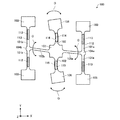
図1は、第1実施形態の角速度検出装置の構成について説明するための図である。
[First Embodiment]
FIG. 1 is a diagram for explaining the configuration of the angular velocity detection device of the first embodiment.
第1実施形態の角速度検出装置1は、ジャイロセンサー素子100と角速度検出用IC10を含んで構成されている。
The angular
ジャイロセンサー素子100(本発明における振動子の一例)は、駆動電極と検出電極が配置された振動片が不図示のパッケージに封止されて構成されている。一般的に、振動片のインピーダンスをできるだけ小さくして発振効率を高めるためにパッケージ内の気密性が確保されている。 The gyro sensor element 100 (an example of a vibrator in the present invention) is configured by sealing a vibrating piece in which a drive electrode and a detection electrode are arranged in a package (not shown). Generally, hermeticity in the package is secured in order to reduce the impedance of the resonator element as much as possible to increase the oscillation efficiency.
ジャイロセンサー素子100の振動片は、例えば、水晶(SiO2)、タンタル酸リチウム(LiTaO3)、ニオブ酸リチウム(LiNbO3)等の圧電単結晶やジルコン酸チタン酸鉛(PZT)等の圧電セラミックスなどの圧電性材料を用いて構成してもよいし、シリコン半導体の表面の一部に、駆動電極に挟まれた酸化亜鉛(ZnO)、窒化アルミニウム(AlN)等の圧電薄膜を配置した構造であってもよい。
The vibrating piece of the
また、この振動片は、例えば、T型の2つの駆動振動腕を有するいわゆるダブルT型であってもよいし、音叉型であってもよいし、三角柱、四角柱、円柱状等の形状の音片型であってもよい。 Further, this vibrating piece may be, for example, a so-called double T type having two T type driving vibrating arms, a tuning fork type, a triangular prism, a quadrangular prism, a cylindrical shape, or the like. A sound piece type may be used.
本実施形態では、ジャイロセンサー素子100は、水晶を材料とするダブルT型の振動片により構成される。
In the present embodiment, the
図2は、本実施形態のジャイロセンサー素子100の振動片の平面図である。
FIG. 2 is a plan view of the resonator element of the
本実施形態のジャイロセンサー素子100は、Zカットの水晶基板により形成されたダブルT型の振動片を有する。水晶を材料とする振動片は、温度変化に対する共振周波数の変動が極めて小さいので、角速度の検出精度を高めることができるという利点がある。なお、図2におけるX軸、Y軸、Z軸は水晶の軸を示す。
The
図2に示すように、ジャイロセンサー素子100の振動片は、2つの駆動用基部104a、104bからそれぞれ駆動振動腕101a、101bが+Y軸方向及び−Y軸方向に延出している。駆動振動腕101aの側面及び上面にはそれぞれ駆動電極112及び113が形成されており、駆動振動腕101bの側面及び上面にはそれぞれ駆動電極113及び112が形成されている。駆動電極112、113は、それぞれ、図1に示した角速度検出用IC10の外部出力端子11、外部入力端子12を介して駆動回路20に接続される。
As shown in FIG. 2, in the vibrating piece of the
駆動用基部104a、104bは、それぞれ−X軸方向と+X軸方向に延びる連結腕105a、105bを介して矩形状の検出用基部107に接続されている。
The drive bases 104a and 104b are connected to a
検出振動腕102は、検出用基部107から+Y軸方向及び−Y軸方向に延出している。検出振動腕102の上面には検出電極114及び115が形成されており、検出振動腕102の側面には共通電極116が形成されている。検出電極114、115は、それぞれ、図1に示した角速度検出用IC10の外部入力端子13、14を介して検出回路30に接続される。また、共通電極116は接地される。
The
駆動振動腕101a、101bの駆動電極112と駆動電極113との間に駆動信号として交流電圧が与えられると、図3に示すように、駆動振動腕101a、101bは逆圧電効果によって矢印Bのように、2本の駆動振動腕101a、101bの先端が互いに接近と離間を繰り返す屈曲振動(励振振動)をする。
When an AC voltage is applied as a drive signal between the
なお、本出願では、ジャイロセンサー素子に角速度がかかっていない状態で上述の屈曲振動(励振振動)するときの、各駆動振動腕における振動エネルギーの大きさ又は振動の振幅の大きさが2本の駆動振動腕で等しいとき、駆動振動腕の振動エネルギーのバランスがとれているという。 In the present application, when the bending vibration (excitation vibration) described above is performed with no angular velocity applied to the gyro sensor element, the magnitude of the vibration energy or the magnitude of the vibration in each drive vibration arm is two. When the drive vibration arms are equal, the vibration energy of the drive vibration arms is balanced.
ここで、ジャイロセンサー素子100の振動片にZ軸を回転軸とした角速度が加わると、駆動振動腕101a、101bは、矢印Bの屈曲振動の方向とZ軸の両方に垂直な方向にコリオリの力を得る。その結果、図4に示すように、連結腕105a、105bは矢印Cで示すような振動をする。そして、検出振動腕102は、連結腕105a、105bの振動(矢印C)に連動して矢印Dのように屈曲振動をする。
Here, when an angular velocity with the Z axis as the rotation axis is applied to the vibrating piece of the
また、駆動振動腕101a、101bの励振振動は、ジャイロセンサー素子の製造バラつきなどによって、駆動振動腕の振動エネルギーのバランスがくずれると、検出振動腕102には漏れ振動を発生させる。この漏れ振動は、コリオリの力に基づいた振動と同様に矢印Dに示す屈曲振動であるが、駆動信号とは同位相である。なお、コリオリ力に伴う振動は駆動振動とは90°ずれた位相である。
In addition, the excitation vibration of the
そして、圧電効果によってこれらの屈曲振動に基づいた交流電荷が、検出振動腕102の検出電極114、115に発生する。ここで、コリオリの力に基づいて発生する交流電荷は、コリオリの力の大きさ(言い換えれば、ジャイロセンサー素子100に加わる角速度の大きさ)に応じて変化する。一方、漏れ振動に基づいて発生する交流電荷は、ジャイロセンサー素子100に加わる角速度の大きさに関係しない。
Then, AC charges based on these bending vibrations are generated in the
なお、図2の構成では、振動片のバランスを良くするために、検出用基部107を中央に配置し、検出用基部107から+Y軸と−Y軸の両方向に検出振動腕102を延出させている。さらに、検出用基部107から+X軸と−X軸の両方向に連結腕105a、105bを延出させ、連結腕105a、105bのそれぞれから、+Y軸と−Y軸の両方向に駆動振動腕101a、101bを延出させている。
In the configuration of FIG. 2, in order to improve the balance of the resonator element, the
また、駆動振動腕101a、101bの先端には、駆動振動腕101a、101bよりも幅の広い矩形状の錘部103が形成されている。駆動振動腕101a、101bの先端に錘部103を形成することにより、コリオリの力を大きくするとともに、所望の共振周波数を比較的短い振動腕で得ることができる。同様に、検出振動腕102の先端には、検出振動腕102よりも幅の広い錘部106が形成されている。検出振動腕102の先端に錘部106を形成することにより、検出電極114、115に発生する交流電荷を大きくすることができる。
Further, a
以上のようにして、ジャイロセンサー素子100は、Z軸を検出軸としてコリオリの力に基づく交流電荷(すなわち、検出信号)と、励振振動の漏れ振動に基づく交流電荷(すなわち、漏れ信号)とを検出電極114、115を介して出力する。
As described above, the
図1に戻り、角速度検出用IC10は、駆動回路20、検出回路30及び基準電源回路40を含んで構成されている。
Returning to FIG. 1, the angular velocity detection IC 10 includes a drive circuit 20, a detection circuit 30, and a reference
駆動回路20は、I/V変換回路(電流電圧変換回路)210、AC増幅回路220及び振幅調整回路230を含んで構成されている。
The drive circuit 20 includes an I / V conversion circuit (current / voltage conversion circuit) 210, an
ジャイロセンサー素子100の振動片に流れた駆動電流は、I/V変換回路210によって交流電圧信号に変換される。
The drive current that has flowed through the resonator element of the
I/V変換回路210から出力された交流電圧信号は、AC増幅回路220及び振幅調整回路230に入力される。AC増幅回路220は、入力された交流電圧信号を増幅し、所定の電圧値でクリップさせて方形波電圧信号22を出力する。振幅調整回路230は、I/V変換回路210が出力する交流電圧信号のレベルに応じて、方形波電圧信号22の振幅を変化させ、駆動電流が一定に保持するようにAC増幅回路220を制御する。
The AC voltage signal output from the I /
方形波電圧信号22は、外部出力端子11を介してジャイロセンサー素子100の振動片の駆動電極112に供給される。このように、ジャイロセンサー素子100は図3に示すような所定の駆動振動を継続して励振している。また、駆動電流を一定に保つことにより、ジャイロセンサー素子100の駆動振動腕101a、101bは一定の振動速度を得ることができる。そのため、コリオリ力を発生させる元となる振動速度は一定となり、感度をより安定にすることができる。
The square
検出回路30は、チャージアンプ回路310、320、差動増幅回路330、AC増幅回路340、同期検波回路350、平滑回路360、可変増幅回路370及びローパスフィルター380を含んで構成されている。
The detection circuit 30 includes
チャージアンプ回路310には、外部入力端子13を介してジャイロセンサー素子100の振動片の検出電極114から検出信号と漏れ信号を含む交流電荷が入力される。
An AC charge including a detection signal and a leakage signal is input to the
同様に、チャージアンプ回路320には、外部入力端子14を介してジャイロセンサー素子100の振動片の検出電極115から検出信号と漏れ信号を含む交流電荷が入力される。
Similarly, AC charge including a detection signal and a leakage signal is input to the
このチャージアンプ回路310及び320は、それぞれ入力された交流電荷を、基準電圧Vrefを基準とした交流電圧信号に変換する。なお、基準電圧Vrefは、基準電源回路40により、電源入力端子15から入力された外部電源に基づいて生成される。
The
差動増幅回路330は、チャージアンプ回路310の出力信号とチャージアンプ回路320の出力信号を差動増幅する。差動増幅回路330は、同相成分を消去し、逆相成分を加算増幅するためのものである。
The
AC増幅回路340は、差動増幅回路330の出力信号を増幅し、被検波信号36を同期検波回路350に出力する。
The
同期検波回路350は、方形波電圧信号22により、被検波信号36に対して同期検波を行う。同期検波回路350は、例えば、検波信号34の電圧レベルが基準電圧Vrefよりも高い時はAC増幅回路340の出力信号を選択し、検波信号34の電圧レベルが基準電圧Vrefよりも低い時はAC増幅回路340の出力信号を基準電圧Vrefに対して反転した信号を選択するスイッチ回路として構成することができる。
The
同期検波回路350の出力信号は、平滑回路360で直流電圧信号に平滑化された後、可変増幅回路370に入力される。
The output signal of the
可変増幅回路370は、平滑回路360の出力信号(直流電圧信号)を、設定された増幅率(又は減衰率)で増幅(又は減衰)して検出感度を調整する。可変増幅回路370で増幅(又は減衰)された信号は、ローパスフィルター380に入力される。
The
ローパスフィルター380は、可変増幅回路370の出力信号を使用に適した周波数帯域に制限する回路であり、角速度検出信号32を生成する。そして、角速度検出信号32は外部出力端子17を介して外部に出力される。
The low-
次に、図1のA点〜G点における信号波形の一例を示して、第1実施形態の角速度検出装置1の角速度検出動作についてより具体的に説明する。
Next, an example of signal waveforms at points A to G in FIG. 1 will be shown to describe the angular velocity detection operation of the angular
図5は、角速度検出装置1が静止している時の信号波形の一例を示す図である。図5において横軸は時間、縦軸は電圧を表す。
FIG. 5 is a diagram illustrating an example of a signal waveform when the angular
ジャイロセンサー素子100の振動片が振動している状態では、I/V変換回路210の出力(A点)には、ジャイロセンサー素子100の振動片の駆動電極113からフィードバックされた電流が変換された一定周波数の交流電圧が発生している。すなわち、I/V変換回路210の出力(A点)には、一定周波数の正弦波電圧信号が発生している。
In a state where the vibrating piece of the
そして、AC増幅回路220の出力(B点)には、I/V変換回路210の出力信号(A点の信号)が増幅された、振幅が一定値Vcの方形波電圧信号が発生する。
Then, at the output (point B) of the
ジャイロセンサー素子100に角速度が加わっていない場合は、ジャイロセンサー素子100の振動片の検出電極114、115には角速度の検出信号は発生しないが、漏れ信号は発生する。
When the angular velocity is not applied to the
ジャイロセンサー素子100の検出電極114及び115に発生した漏れ信号(交流電荷)は、それぞれチャージアンプ回路310及び320により、交流電圧信号に変換される。ここでは、チャージアンプ回路310と320から出力される交流電圧信号は逆相であるとしている。その結果、チャージアンプ回路310及び320の出力(C点及びD点)には、AC増幅回路220の出力信号(B点の信号)と同じ周波数の正弦波電圧信号が発生する。ここで、チャージアンプ回路310の出力信号(C点の信号)の位相は、AC増幅回路220の出力信号(B点の信号)に対して90°ずれている。また、チャージアンプ回路320の出力信号(D点の信号)の位相は、チャージアンプ回路310の出力信号(C点の信号)に対して逆位相である(180°ずれている)。
Leakage signals (AC charges) generated at the
チャージアンプ回路310及び320の出力信号(C点の信号及びD点の信号)は差動増幅回路330により差動増幅され、AC増幅回路340の出力(E点)には、チャージアンプ回路310の出力(C点)に発生する正弦波電圧信号と同じ周波数で同位相の正弦波電圧信号が発生する。AC増幅回路340の出力(E点)に発生するこの正弦波電圧信号は、ジャイロセンサー素子100の振動片の検出電極114、115に発生する漏れ信号に対応する信号である。
The output signals of the
AC増幅回路340の出力信号(E点の信号)は、同期検波回路350により、AC増幅回路220が出力する方形波電圧信号22(B点の信号)に基づいて同期検波される。
The output signal (point E signal) of the
ここで、AC増幅回路340の出力信号(E点の信号)と方形波電圧信号22(B点の信号)は90°だけ位相がずれているので、同期検波回路350の出力信号(F点の信号)において、基準電圧Vrefよりも高い電圧の積分量と基準電圧Vrefよりも低い電圧の積分量が等しくなる。その結果、漏れ信号はキャンセルされ、ローパスフィルター380の出力(G点)には角速度が0であることを示す基準電圧Vrefの直流電圧信号が発生する。
Here, since the output signal (point E signal) of the
図6は、角速度検出装置1に角速度が加わっている時の信号波形の一例を示す図である。図6において横軸は時間、縦軸は電圧を表す。
FIG. 6 is a diagram illustrating an example of a signal waveform when an angular velocity is applied to the angular
A点及びB点の各信号波形は図5と同じであり、その説明を省略する。 The signal waveforms at points A and B are the same as those in FIG.
ジャイロセンサー素子100に角速度が加わると、ジャイロセンサー素子100の振動片の検出電極114、115には検出信号と漏れ信号が発生する。この検出信号のレベルはコリオリ力の大きさに応じて変化する。一方、漏れ信号は図5と同じ信号波形になり、キャンセルされる。そのため、図6では検出信号のみに着目した信号波形を示しており、以下の説明においても検出信号のみに着目して説明する。
When an angular velocity is applied to the
ジャイロセンサー素子100の振動片の検出電極114及び115に発生した検出信号(交流電荷)は、それぞれチャージアンプ回路310及び320により、交流電圧信号に変換される。その結果、チャージアンプ回路310及び320の出力(C点及びD点)には、AC増幅回路220の出力信号(B点の信号)と同じ周波数の正弦波電圧信号が発生する。ここで、チャージアンプ回路310の出力信号(C点の信号)の位相は、AC増幅回路220の出力信号(B点の信号)と同位相である。また、チャージアンプ回路320の出力信号(D点の信号)の位相は、チャージアンプ回路310の出力信号(C点の信号)に対して逆位相である(180°ずれている)。
Detection signals (AC charges) generated at the
チャージアンプ回路310及び320の出力信号(C点の信号及びD点の信号)は差動増幅回路330により差動増幅され、AC増幅回路340の出力(E点)には、チャージアンプ回路310の出力(C点)に発生する正弦波電圧信号と同じ周波数で同位相の正弦波電圧信号が発生する。AC増幅回路340の出力(E点)に発生するこの正弦波電圧信号は、ジャイロセンサー素子100の検出電極114、115に発生する検出信号に対応する信号である。
The output signals of the
AC増幅回路340の出力信号(E点の信号)は、同期検波回路350により、AC増幅回路220が出力する方形波電圧信号22(B点の信号)に基づいて同期検波される。ここで、AC増幅回路340の出力信号(E点の信号)と方形波電圧信号22(B点の信号)は同位相であるので、同期検波回路350の出力信号(F点の信号)は、AC増幅回路340の出力信号(E点の信号)が全波整流された信号となる。その結果、ローパスフィルター380の出力(G点)には、角速度の大きさに応じた電圧値V1の直流電圧信号(すなわち、角速度検出信号32)が発生する。
The output signal (point E signal) of the
なお、角速度検出装置1に図6と逆方向の角速度が加わった場合には、チャージアンプ回路310の出力信号(C点の信号)及びチャージアンプ回路320の出力信号(D点の信号)がともに基準電圧Vrefを中心として反転した波形になる。その結果、角速度検出信号32は、図6とは逆に基準電圧Vrefよりも低い電圧の信号になる。
When an angular velocity in the direction opposite to that in FIG. 6 is applied to the
このようにして角速度検出装置1は角速度を検出することができる。そして、角速度検出信号32は、その電圧値がコリオリの力の大きさ(角速度の大きさ)に比例し、その極性が回転方向により決まるので、角速度検出信号32に基づいて角速度検出装置1に加えられた角速度を計算することができる。
In this way, the angular
図1に戻り、角速度検出用IC10は、異常診断回路60を含んで構成されている。
Returning to FIG. 1, the angular velocity detection IC 10 includes an
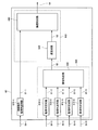
図7は、異常診断回路60の構成について説明するための図である。図7に示す例において、異常診断回路60は、発振動作監視判定回路610−1、監視判定回路610−3〜610−6、論理和回路620、遅延回路630及び論理和回路640を含んで構成されている。
FIG. 7 is a diagram for explaining the configuration of the
発振動作監視判定回路610−1は、監視対象信号50−1を監視し、ジャイロセンサー素子100が所定の発振周波数で動作しているか否かを判定し、ジャイロセンサー素子100が所定の発振周波数で動作しているか否かを表す発振動作判定信号61−1を生成する。同様に、監視判定回路610−3〜610−6は、それぞれ監視対象信号50−3〜50−6を監視し、監視対象信号50−3〜50−6の異常の有無を判定し、監視対象信号50−3〜50−6に異常があるか否かを表す判定信号61−3〜61−6を生成する。
The oscillation operation monitoring determination circuit 610-1 monitors the monitoring target signal 50-1, determines whether or not the
論理和回路620は、判定信号61−3〜61−6を受け付け、その論理和を異常フラグ信号82として生成する。
The
遅延回路630は、異常フラグ信号82の立ち上がりタイミング及び立ち下がりタイミングの少なくとも一方を遅延させて遅延信号63を生成する。遅延回路620は、例えば、シフトレジスターを用いて構成され、ジャイロセンサー素子100が出力する信号に基づいて生成されたクロック信号(例えば、方形波電圧信号22や、方形波電圧信号22を分周した信号等)を用いて、異常フラグ信号82の立ち上がりタイミング及び立ち下がりタイミングの少なくとも一方を所定時間だけ遅延させて遅延信号63を生成してもよい。
The
論理和回路640は、発振動作判定信号61−1及び遅延信号63を受け付け、その論理和を異常判定信号64として生成する。
The
なお、図7に示す例では、発振動作監視判定回路610−1が本発明における発振動作判定部に、監視判定回路610−3〜610−6及び論理和回路620が本発明における異常フラグ生成部800に、遅延回路630及び論理和回路640が本発明における異常判定出力部900にそれぞれ対応する。
In the example shown in FIG. 7, the oscillation operation monitoring determination circuit 610-1 is the oscillation operation determination unit in the present invention, and the monitoring determination circuits 610-3 to 610-6 and the
本実施形態においては、発振動作判定信号61−1、判定信号61−3〜61−6、異常フラグ信号82、遅延信号63及び異常判定信号64は、正常を表す値をローレベル(L)、異常を表す値をハイレベル(H)とする電圧信号である。したがって論理和回路630は、監視対象信号50−3〜50−6のいずれかに異常が発生している期間においてはハイレベル、他の期間においてはローレベルの異常フラグ信号82を出力する。
In the present embodiment, the oscillation operation determination signal 61-1, the determination signals 61-3 to 61-6, the
本実施形態における異常判定出力部900は、発振動作判定信号61−1が異常を表す値である場合には、角速度検出装置1の動作の異常を表す値の異常判定信号64を出力し、発振動作判定信号61−1が正常を表す値である場合には、ジャイロセンサー素子100が出力する信号に基づいて生成されたクロック信号を用いて、異常フラグ信号82が正常を表す値から異常を表す値に変化してから、異常を表す値が第1の時間T1以上継続した後に、異常判定信号64を、正常を表す値から異常を表す値に変更して出力する。
When the oscillation operation determination signal 61-1 has a value indicating an abnormality, the abnormality
図8は、発振動作判定信号61−1、異常フラグ信号82、遅延信号63、異常判定信号64のタイミングチャートである。
FIG. 8 is a timing chart of the oscillation operation determination signal 61-1, the
時刻t1から時刻t2までの期間において、ジャイロセンサー素子100が所定の発振周波数で動作していない場合には、発振動作監視判定回路610−1は、発振動作判定信号60−1としてハイレベルの電圧信号を出力する。この場合には、時刻t1から時刻t2までの期間において、他の監視判定回路610−3〜610−6での判定結果にかかわらず、論理和回路640は、異常判定信号64としてハイレベルの電圧信号を出力する。
In the period from time t1 to time t2, when the
時刻t2以降においては、ジャイロセンサー素子100が所定の発振周波数で動作している場合であり、発振動作監視判定回路610−1は、発振動作判定信号60−1としてローレベルの電圧信号を出力する。
After time t2, the
時刻t4から時刻t6までの期間において、監視判定回路610−3〜610−6での判定結果のいずれかが異常を表している場合には、論理和回路620は、異常フラグ信号82としてハイレベルの電圧信号を出力する。
In the period from time t4 to time t6, if any of the determination results in the monitoring determination circuits 610-3 to 610-6 indicates an abnormality, the
遅延回路630は、ジャイロセンサー素子100が出力する信号に基づいて生成されたクロック信号を用いて、異常フラグ信号82がローレベル(正常を表す値)からハイレベル(異常を表す値)に変化してから、ハイレベル(異常を表す値)が第1の時間T1以上継続した後に、遅延信号63を、ローレベルからハイレベルに変更して出力する。図8に示す例では、時刻t4から第1の時間T1だけ遅れた時刻t5に、遅延信号63を、ローレベルからハイレベルに変更して出力する。
The
この結果、論理和回路640は、異常フラグ信号82がローレベル(正常を表す値)からハイレベル(異常を表す値)に変化してから、ハイレベル(異常を表す値)が第1の時間T1以上継続した後に、異常判定信号64を、ローレベル(正常を表す値)からハイレベル(異常を表す値)に変更して出力することになる。図8に示す例では、時刻t4から第1の時間T1だけ遅れた時刻t5に、異常判定信号64を、ローレベル(正常を表す値)からハイレベル(異常を表す値)に変更して出力する。
As a result, the
このように、本実施形態によれば、ジャイロセンサー素子100が所定の発振周波数で動作していない場合には、他の監視対象信号50−3〜50−6の異常の有無にかかわらず、角速度検出装置1の動作の異常を表す異常判定信号64を出力することができる。これにより、ジャイロセンサー素子100が所定の発振周波数で動作していない場合という、重要な異常を確実に通知することができる。
As described above, according to the present embodiment, when the
また、異常フラグ信号が正常を表す値から異常を表す値に変化してから、異常を表す値が第1の時間T1以上継続した後に、異常判定信号を、正常を表す値から異常を表す値に変更して出力するため、瞬間的な(第1の時間T1よりも短い期間の)ノイズ等の影響で、監視対象信号50−3〜50−6の値が瞬間的に異常になる場合には、異常判定信号が異常を表す値にならない。これにより、瞬間的なノイズ等の影響による誤診断を減らすことができる。 In addition, after the abnormality flag signal has changed from a value representing normality to a value representing abnormality, the abnormality determination signal is changed from a value representing normality to a value representing abnormality after the value representing abnormality has continued for a first time T1 or more. When the values of the monitoring target signals 50-3 to 50-6 become instantaneously abnormal due to instantaneous noise (during a period shorter than the first time T1) or the like. The abnormality determination signal does not become a value indicating abnormality. This can reduce misdiagnosis due to instantaneous noise and the like.
さらに、ジャイロセンサー素子100が所定の発振周波数で動作している場合にのみ遅延回路630で第1の時間T1をカウントすればよいので、ジャイロセンサー素子100が出力する信号に基づいて生成されたクロック信号を用いて第1の時間T1をカウントすることができる。
Furthermore, since the
したがって、信頼性の高い異常判定出力が可能な角速度検出装置1を実現することができる。
Therefore, it is possible to realize the angular
[第2実施形態]
図9は、第2実施形態の角速度検出装置の構成について説明するための図である。図1を用いて説明した角速度検出装置1と同一の構成には同一の符号を付し、その詳細な説明を省略する。
[Second Embodiment]
FIG. 9 is a diagram for explaining the configuration of the angular velocity detection device of the second embodiment. The same components as those in the angular
第2実施形態の角速度検出装置1Aは、ジャイロセンサー素子100と角速度検出用IC10Aを含んで構成されている。角速度検出用IC10Aは、図1を用いて説明した角速度検出用IC10の異常診断回路60に代えて異常診断回路60Aを含む構成となっている。異常診断回路60Aは、監視対象信号50−1及び50−3〜50−6に加えて、AC増幅回路220の出力信号を監視対象信号50−2として監視する。
An angular velocity detection device 1A according to the second embodiment includes a
図10は、異常診断回路60Aの構成について説明するための図である。図10に示す例において、異常診断回路60Aは、図7に示す異常診断回路60の構成に加えて、駆動振幅監視判定回路610−2を含んで構成されている。また、論理和回路640に代えて論理和回路640Aを含んで構成されている。
FIG. 10 is a diagram for explaining the configuration of the
駆動振幅監視判定回路610−2は、監視対象信号50−2を監視し、ジャイロセンサー素子100が所定の駆動振幅で動作しているか否かを判定し、ジャイロセンサー素子100が所定の駆動振幅で動作しているか否かを表す駆動振幅判定信号61−2を生成する。
The drive amplitude monitoring determination circuit 610-2 monitors the monitoring target signal 50-2, determines whether or not the
論理和回路640Aは、発振動作判定信号61−1、駆動振幅判定信号61−2及び遅延信号63を受け付け、その論理和を異常判定信号64Aとして生成する。
The OR
なお、図10に示す例では、駆動振幅監視判定回路610−2が本発明における駆動振幅判定部に、遅延回路630及び論理和回路640Aが本発明における異常判定出力部900Aにそれぞれ対応する。
In the example shown in FIG. 10, the drive amplitude monitoring determination circuit 610-2 corresponds to the drive amplitude determination unit in the present invention, and the
また、本実施形態においては、駆動振幅判定信号61−2は、正常を表す値をローレベル(L)、異常を表す値をハイレベル(H)とする電圧信号である。 In the present embodiment, the drive amplitude determination signal 61-2 is a voltage signal that sets a value representing normality to a low level (L) and a value representing abnormality to a high level (H).
本実施形態における異常判定出力部900Aは、発振動作判定信号61−1と駆動振幅判定信号61−2と異常フラグ信号82とを受け付け、発振動作判定信号61−1及び駆動振幅判定信号61−2の少なくとも一方が異常を表す値である場合には、角速度検出装置1Aの動作の異常を表す値の異常判定信号64Aを出力し、発振動作判定信号61−1及び駆動振幅判定信号61−2のいずれもが正常を表す値である場合には、ジャイロセンサー素子100が出力する信号に基づいて生成されたクロック信号を用いて、異常フラグ信号82が正常を表す値から異常を表す値に変化してから、異常を表す値が第1の時間T1以上継続した後に、異常判定信号64Aを、正常を表す値から異常を表す値に変更して出力する。
The abnormality
図11は、発振動作判定信号61−1、駆動振幅判定信号61−2、異常フラグ信号82、遅延信号63、異常判定信号64Aのタイミングチャートである。
FIG. 11 is a timing chart of the oscillation operation determination signal 61-1, the drive amplitude determination signal 61-2, the
時刻t1から時刻t2までの期間において、ジャイロセンサー素子100が所定の発振周波数で動作していない場合には、発振動作監視判定回路610−1は、発振動作判定信号60−1としてハイレベルの電圧信号を出力する。また、時刻t1から時刻t3までの期間において、ジャイロセンサー素子100が所定の駆動振幅で動作していない場合には、駆動振幅監視判定回路610−2は、駆動振幅判定信号60−2としてハイレベルの電圧信号を出力する。この場合には、時刻t1から時刻t3までの期間において、他の監視判定回路610−3〜610−6での判定結果にかかわらず、論理和回路640Aは、異常判定信号64Aとしてハイレベルの電圧信号を出力する。
In the period from time t1 to time t2, when the
時刻t2以降においては、ジャイロセンサー素子100が所定の発振周波数で動作している場合であり、発振動作監視判定回路610−1は、発振動作判定信号60−1としてローレベルの電圧信号を出力する。また、時刻t3以降においては、ジャイロセンサー素子100が所定の駆動振幅で動作している場合であり、駆動振幅監視判定回路610−2は、駆動振幅判定信号60−2としてローレベルの電圧信号を出力する。
After time t2, the
時刻t4から時刻t6までの期間において、監視判定回路610−3〜610−6での判定結果のいずれかが異常を表している場合には、論理和回路620は、異常フラグ信号82としてハイレベルの電圧信号を出力する。
In the period from time t4 to time t6, if any of the determination results in the monitoring determination circuits 610-3 to 610-6 indicates an abnormality, the
遅延回路630は、ジャイロセンサー素子100が出力する信号に基づいて生成されたクロック信号を用いて、異常フラグ信号82がローレベル(正常を表す値)からハイレベル(異常を表す値)に変化してから、ハイレベル(異常を表す値)が第1の時間T1以上継続した後に、遅延信号63を、ローレベルからハイレベルに変更して出力する。図11に示す例では、時刻t4から第1の時間T1だけ遅れた時刻t5に、遅延信号63を、ローレベルからハイレベルに変更して出力する。
The
この結果、論理和回路640は、異常フラグ信号82がローレベル(正常を表す値)からハイレベル(異常を表す値)に変化してから、ハイレベル(異常を表す値)が第1の時間T1以上継続した後に、異常判定信号64Aを、ローレベル(正常を表す値)からハイレベル(異常を表す値)に変更して出力することになる。図11に示す例では、時刻t4から第1の時間T1だけ遅れた時刻t5に、異常判定信号64Aを、ローレベル(正常を表す値)からハイレベル(異常を表す値)に変更して出力する。
As a result, the
本実施形態によれば、上述した第1実施形態の効果に加えて、ジャイロセンサー素子100が所定の発振周波数で動作していない場合に加えて、ジャイロセンサー素子100が所定の駆動振幅で動作していない場合にも、他の監視対象信号50−3〜50−6の異常の有無にかかわらず異常判定信号64Aを出力することができる。これにより、ジャイロセンサー素子100が所定の駆動振幅で動作していない場合という、重要な異常を確実に通知することができる。したがって、より信頼性の高い異常判定出力が可能な物理量検出装置を実現することができる。
According to the present embodiment, in addition to the effects of the first embodiment described above, in addition to the case where the
[第1実施形態及び第2実施形態の変形例]
上述した第1実施形態及び第2実施形態において、遅延回路630は、第1の時間T1を可変に構成されていてもよい。例えば、遅延回路620がシフトレジスターを用いて遅延時間をカウントする場合において、メモリーに記憶された設定値に基づいてカウント値を可変に構成したり、クロック信号の分周比率を可変に構成したりしてもよい。
[Modifications of First Embodiment and Second Embodiment]
In the first and second embodiments described above, the
第1の時間T1を可変に構成することにより、要求される信頼度に応じて所定時間Tを変更することが可能になる。例えば、外部出力端子17から出力される角速度検出信号32をデジタル化してマイクロコンピューター等で用いる場合に、サンプリングレートに応じて第1の時間T1を設定することができる。
By configuring the first time T1 to be variable, the predetermined time T can be changed according to the required reliability. For example, when the angular
上述した第1実施形態、第2実施形態及びこれらの変形例において、異常判定出力部900又は900Aは、異常フラグ信号82が異常を表す値から正常を表す値に変化してから第2の時間に亘る異常フラグ信号に基づいて、異常判定信号64又は64Aを、異常を表す値から正常を表す値に変化させて出力してもよい。図7及び図10に示す例では、遅延回路630が、異常フラグ信号82が異常を表す値から正常を表す値に変化してから第2の時間に亘る異常フラグ信号に基づいて、遅延信号63を、異常を表す値から正常を表す値に変化させて出力することにより実現できる。
In the first embodiment, the second embodiment, and the modifications thereof described above, the abnormality
図12は、ジャイロセンサー素子100が所定の発振周波数で動作し、所定の駆動振幅で動作している場合において、監視対象信号50−3〜50−6のいずれかに異常が発生した場合における発振動作判定信号60−1及び駆動振幅判定信号60−2、異常フラグ信号82、遅延信号63及び異常判定信号64又は64A、角速度検出信号32のタイミングチャートである。
FIG. 12 shows an oscillation in the case where an abnormality occurs in any of the monitoring target signals 50-3 to 50-6 when the
ジャイロセンサー素子100が所定の発振周波数で動作し、所定の駆動振幅で動作しているため、発振動作判定信号60−1及び駆動振幅判定信号60−2は、図12に示す期間中においてはローレベルである。
Since the
以下、例えば電源入力端子15から供給される電源電圧が一時的に基準値以下まで低下した場合等に、監視判定回路610−6が電源電圧に異常が発生したものと判定して判定信号61−6をローレベルからハイレベルに変更して出力し、論理和回路620が異常フラグ信号82をローレベルからハイレベルに変更して出力する場合を例にとり説明する。
Hereinafter, for example, when the power supply voltage supplied from the
時刻t10において電源電圧(監視対象信号50−6)に異常が発生すると、監視判定回路610−6は、判定信号61−6をローレベルからハイレベルに変更して出力し、論理和回路620が異常フラグ信号82をローレベルからハイレベルに変更して出力する。上述の各実施形態で説明したように、遅延回路630は、異常フラグ信号82の立ち上がりタイミングを第1の時間T1だけ遅延させて、遅延信号63を時刻t11にローレベルからハイレベルに変更して出力する。この遅延信号63に基づいて、論理和回路640又は640Aは、異常判定信号64又は64Aを時刻t11にローレベルからハイレベルに変更して出力する。
When an abnormality occurs in the power supply voltage (monitor target signal 50-6) at time t10, the monitoring determination circuit 610-6 changes the determination signal 61-6 from the low level to the high level and outputs it, and the
時刻t10で発生した異常が時刻t13で正常に戻ると、監視判定回路610−6は、判定信号61−6をハイレベルからローレベルに変更して出力し、論理和回路620が異常フラグ信号82をハイレベルからローレベルに変更して出力する。
When the abnormality occurring at time t10 returns to normal at time t13, the monitoring determination circuit 610-6 changes the determination signal 61-6 from high level to low level and outputs it, and the
一方、角速度検出信号32は、検出回路30を通って出力されるため、時刻t10で発生した異常の影響を受けた角速度検出信号32は、遅延時間Tdだけ遅れて時刻t12に出力される。また、時刻t10で発生した異常が時刻t13まで継続すると、異常の影響を受けた角速度検出信号32は、遅延時間Tdだけ遅れた時刻t14まで継続する。
On the other hand, since the angular
すなわち、実際に異常が発生して異常フラグ信号82が出力される異常発生区間は、時刻t10から時刻t13までであるが、発生した異常の影響を受けた角速度検出信号32が出力される異常出力区間は、遅延時間Tdだけ遅れた時刻t12から時刻t14までである。したがって、時刻t13から時刻t14までの期間では、異常フラグ信号82が正常を表しているにもかかわらず、角速度検出信号32は異常の影響を受けた信号となる。そのため、異常フラグ信号82がローレベルに戻るタイミングを、そのまま異常判定信号64又は64Aをローレベルに戻すタイミングとして用いると、高い信頼性を要求される用途において問題となる可能性がある。
In other words, the abnormality occurrence section in which abnormality actually occurs and the
本変形例においては、遅延回路630は、時刻t13に異常フラグ信号82がハイレベル(異常を表す値)からローレベル(正常を表す値)に変化してから第2の時間T2以上に亘る異常フラグ信号82に基づいて、時刻t15に遅延信号63をハイレベル(異常を表す値)からローレベル(正常を表す値)に変化させて出力する。
In the present modification, the
例えば、遅延回路630は、時刻t13に異常フラグ信号82がハイレベル(異常を表す値)からローレベル(正常を表す値)に変化してから第2の時間T2だけ経過した後に、遅延信号63をハイレベル(異常を表す値)からローレベル(正常を表す値)に変化させて出力する。この遅延信号63に基づいて、論理和回路640又は640Aは、時刻t13に異常フラグ信号82がハイレベル(異常を表す値)からローレベル(正常を表す値)に変化してから第2の時間T2だけ経過した後に、異常判定信号64又は64Aをハイレベル(異常を表す値)からローレベル(正常を表す値)に変化させて出力する。
For example, the
このように、本変形例によれば、異常フラグ信号82が異常を表す値から正常を表す値に変化してから、第2の時間T2以上に亘る異常フラグ信号82に基づいて、異常判定信号64又は64Aを、異常を表す値から正常を表す値に変化させて出力するため、異常フラグ信号82が正常を表す値に変化しても、少なくとも第2の時間T2に亘っては、異常判定信号64又は64Aは正常を表す値に変化しない。そのため、角速度検出信号32が異常値を示しているにもかかわらず、正常を表す異常判定信号64又は64Aを出力してしまう可能性が小さくなる。したがって、より信頼性の高い異常判定出力が可能な角速度検出装置を実現することができる。
Thus, according to this modification, after the
上述した第1実施形態、第2実施形態及びこれらの変形例において、異常判定出力部900又は900Aは、異常フラグ信号82が異常を表す値から正常を表す値に変化してから、正常を表す値が第2の時間T以上継続した後に、異常判定信号64又は64Aを、異常を表す値から正常を表す値に変更して出力してもよい。
In the first embodiment, the second embodiment, and the modifications described above, the abnormality
図7及び図10に示す例では、遅延回路630は、異常フラグ信号82が異常を表す値から正常を表す値に変化してから、正常を表す値が第2の時間T2以上継続した後に、異常判定信号82を、異常を表す値から正常を表す値に変更して出力してもよい。すなわち、遅延回路630は、時刻t13に異常フラグ信号82がハイレベル(異常を表す値)からローレベル(正常を表す値)に変化してから、ローレベルの異常フラグ信号82が第2の時間T2以上継続した後に、遅延信号63をハイレベル(異常を表す値)からローレベル(正常を表す値)に変化させて出力してもよい。この遅延信号63に基づいて、論理和回路640又は640Aは、時刻t13に異常フラグ信号82がハイレベル(異常を表す値)から、ローレベルの異常フラグ信号82が第2の時間T2以上継続した後に、異常判定信号64又は64Aをハイレベル(異常を表す値)からローレベル(正常を表す値)に変化させて出力する。
In the example shown in FIGS. 7 and 10, the
このように構成することにより、異常フラグ信号82が異常を表す値から正常を表す値に変化してから、正常を表す値が第2の時間T2以上継続した後に、異常判定信号64又は64Aを、異常を表す値から正常を表す値に変更して出力するため、異常フラグ信号82が正常を表す値に変化しても、少なくとも第2の時間T2に亘っては、異常判定信号64又は64Aは正常を表す値に変化しない。加えて、第2の時間T2に満たない時間だけ異常フラグ信号82が正常を表す値になっても、異常判定信号64又は64Aは正常を表す値に変化しない。そのため、角速度検出信号32が異常値を示しているにもかかわらず、正常を表す異常判定信号64又は64Aを出力してしまう可能性が小さくなる。したがって、より信頼性の高い異常判定出力が可能な角速度検出装置を実現することができる。
With this configuration, after the
図13は、ローパスフィルター380の群遅延時間と周波数との関係の一例を示すグラフである。横軸は周波数(対数)、縦軸は群遅延時間を表す。
FIG. 13 is a graph showing an example of the relationship between the group delay time of the low-
本実施の形態において、所定時間Tを、ローパスフィルター380の直流(0Hz)からカットオフ周波数fcまでの周波数帯域(通過帯域)における最小群遅延時間τ1以上としてもよい。
In the present embodiment, the predetermined time T may be equal to or longer than the minimum group delay time τ1 in the frequency band (pass band) from the direct current (0 Hz) of the low-
図1を用いて説明した検出回路30のように、ローパスフィルター380を介して角速度検出信号32を生成する場合には、ローパスフィルター380での遅延時間が他の回路ブロックにおける遅延時間よりも数桁程度大きいことが通常である。すなわち、ローパスフィルター380での遅延時間が、ほぼ検出回路30における信号の遅延時間Tdとなるのが通常である。
When the angular
したがって、第2の時間T2をローパスフィルター380の直流(0Hz)からカットオフ周波数fcまでの周波数帯域(通過帯域)における最小群遅延時間τ1以上とすることにより、角速度検出信号32が異常値を示しているにもかかわらず、正常を表す異常判定信号64又は64Aを出力してしまう可能性がさらに小さくなる。したがって、より信頼性の高い異常判定出力が可能な角速度検出装置を実現することができる。
Therefore, by setting the second time T2 to be equal to or longer than the minimum group delay time τ1 in the frequency band (pass band) from the direct current (0 Hz) of the low-
また、本実施の形態において、第2の時間T2を、ローパスフィルター380の最大群遅延時間τ2以上としてもよい。
In the present embodiment, the second time T2 may be greater than or equal to the maximum group delay time τ2 of the low-
第2の時間T2をローパスフィルター380の最大群遅延時間τ2以上とすることにより、角速度検出信号32が異常値を示しているにもかかわらず、正常を表す異常判定信号64又は64Aを出力してしまう可能性が極めて小さくなる。したがって、より信頼性の高い異常判定出力が可能な物理量検出装置を実現することができる。
By setting the second time T2 to be equal to or longer than the maximum group delay time τ2 of the low-
さらに、遅延回路630は、第2の時間T2を可変に構成されていてもよい。例えば、遅延回路620がシフトレジスターを用いて遅延時間をカウントする場合において、メモリーに記憶された設定値に基づいてカウント値を可変に構成したり、クロック信号の分周比率を可変に構成したりしてもよい。
Further, the
第2の時間T2を可変に構成することにより、要求される信頼度に応じて第2の時間T2を変更することが可能になる。 By configuring the second time T2 to be variable, it is possible to change the second time T2 according to the required reliability.
2.物理量検出装置の異常診断システム及び異常診断方法
以下では、物理量として角速度を検出する物理量検出装置(角速度検出装置)の異常診断システム及び異常診断方法を例にとり説明するが、本発明は、角速度、加速度、地磁気、圧力等の様々な物理量のいずれかを検出することができる装置の異常診断システム及び異常診断方法に適用可能である。
2. Abnormality Diagnosis System and Abnormality Diagnosis Method of Physical Quantity Detection Device Hereinafter, an abnormality diagnosis system and an abnormality diagnosis method of a physical quantity detection device (angular velocity detection device) that detects an angular velocity as a physical quantity will be described as an example. The present invention can be applied to an abnormality diagnosis system and an abnormality diagnosis method for an apparatus that can detect any of various physical quantities such as geomagnetism and pressure.
[第1実施形態]
図14は、角速度検出装置の異常診断システムの構成の一例を示す図である。
[First Embodiment]
FIG. 14 is a diagram illustrating an example of a configuration of an abnormality diagnosis system for an angular velocity detection device.
図14に示すように、異常診断システム1000は、第1実施形態の角速度検出装置1とマイクロコンピューター2を含んで構成されている。
As shown in FIG. 14, the abnormality diagnosis system 1000 includes the angular
マイクロコンピューター2は、外部入力端子16から出力される異常判定信号64を受け付け、異常判定信号64に基づいて角速度検出装置1の動作に異常があるか否かを判定し、異常診断信号4を出力する。すなわち、マイクロコンピューター2は、本発明における異常診断装置として機能する。そして、異常診断信号4は、例えば、不図示の表示装置に入力されて角速度検出装置1が異常であれば警告表示される。
The
異常判定信号64に基づいて角速度検出装置1の動作に異常があるか否かをマイクロコンピューター2で診断するため、複雑な演算処理を要する診断手法(例えば、異常判定信号64の履歴情報を統計処理して診断する等)も可能となる。したがって、より信頼性の高い異常診断が可能な角速度検出装置の異常診断システムを実現することができる。
In order to diagnose whether or not the operation of the angular
図15は、図14に示す異常診断システム1000による角速度検出装置の異常診断方法を示すフローチャートの一例を示す図である。 FIG. 15 is a diagram showing an example of a flowchart showing an abnormality diagnosis method for the angular velocity detection device by the abnormality diagnosis system 1000 shown in FIG.
まず、ジャイロセンサー素子100が所定の発振周波数で動作しているか否かを検出する(発振動作検出工程S100)。本実施形態においては、角速度検出装置1の異常診断回路60に含まれる発振動作監視判定回路610−1で発振動作検出工程S100を行う。
First, it is detected whether or not the
次に、監視対象信号50−3〜50−6の異常の有無を検出する(異常検出工程S102)。本実施形態においては、角速度検出装置1の異常診断回路60に含まれる監視判定回路610−3〜610−5で異常検出工程S102を行う。
Next, the presence or absence of abnormality of the monitoring target signals 50-3 to 50-6 is detected (abnormality detection step S102). In the present embodiment, the abnormality detection step S102 is performed by the monitoring determination circuits 610-3 to 610-5 included in the
なお、発振動作検出工程S100と異常検出工程S102との順序は任意であり、発振動作検出工程S100と異常検出工程S102とを並行して行ってもよい。 The order of the oscillation operation detection step S100 and the abnormality detection step S102 is arbitrary, and the oscillation operation detection step S100 and the abnormality detection step S102 may be performed in parallel.
次に、角速度検出装置1の動作に異常があるか否かを判定する(判定工程S104)。判定工程S104においては、発振動作検出工程S100における検出結果が異常である場合には、判定結果を異常とし、発振動作検出工程S100における検出結果が正常である場合には、ジャイロセンサー素子100が出力する信号に基づいて生成されたクロック信号を用いて、異常検出工程S102における検出結果が正常から異常に変化してから、正常を表す検出結果が第1の時間以上継続した後に、判定結果を正常から異常へ変更する。本実施形態においては、マイクロコンピューター2で判定工程S104を行う。
Next, it is determined whether or not there is an abnormality in the operation of the angular velocity detection device 1 (determination step S104). In the determination step S104, if the detection result in the oscillation operation detection step S100 is abnormal, the determination result is abnormal, and if the detection result in the oscillation operation detection step S100 is normal, the
本実施形態によれば、ジャイロセンサー素子100が所定の発振周波数で動作していない場合には、他の監視対象信号50−3〜50−6の異常の有無にかかわらず判定結果を異常とすることができる。これにより、ジャイロセンサー素子100が所定の発振周波数で動作していない場合という、重要な異常を確実に判定することができる。
According to the present embodiment, when the
また、異常検出工程における検出結果が正常から異常に変化した場合に、第1の時間に亘る異常検出工程における検出結果に基づいて、判定結果を正常から異常へ変更するため、瞬間的な(第1の時間よりも短い期間の)ノイズ等の影響で監視対象信号の値が瞬間的に異常になる場合には、判定結果が異常とはならない。これにより、瞬間的なノイズ等の影響による誤診断を減らすことができる。 In addition, when the detection result in the abnormality detection process changes from normal to abnormal, the determination result is changed from normal to abnormal based on the detection result in the abnormality detection process over the first time. If the value of the monitoring target signal instantaneously becomes abnormal due to the influence of noise or the like (for a period shorter than 1 time), the determination result does not become abnormal. This can reduce misdiagnosis due to instantaneous noise and the like.
したがって、信頼性の高い異常判定出力が可能な物理量検出装置の異常診断方法を実現することができる。 Therefore, it is possible to realize an abnormality diagnosis method for a physical quantity detection device that can output an abnormality determination output with high reliability.
[第2実施形態]
図16は、角速度検出装置の異常診断システムの構成の一例を示す図である。
[Second Embodiment]
FIG. 16 is a diagram illustrating an example of a configuration of an abnormality diagnosis system for an angular velocity detection device.
図16に示すように、異常診断システム1000Aは、第2実施形態の角速度検出装置1Aとマイクロコンピューター2を含んで構成されている。
As shown in FIG. 16, the abnormality diagnosis system 1000A includes the angular velocity detection device 1A and the
第1実施形態の異常診断システム1000と同様に、異常判定信号64Aに基づいて角速度検出装置1Aの動作に異常があるか否かをマイクロコンピューター2で診断するため、複雑な演算処理を要する診断手法(例えば、異常判定信号64Aの履歴情報を統計処理して診断する等)も可能となる。したがって、より信頼性の高い異常診断が可能な角速度検出装置の異常診断システムを実現することができる。
Similar to the abnormality diagnosis system 1000 of the first embodiment, the
図17は、図16に示す異常診断システム1000Aによる角速度検出装置の異常診断方法を示すフローチャートの一例を示す図である。 FIG. 17 is a diagram illustrating an example of a flowchart illustrating an abnormality diagnosis method for the angular velocity detection device by the abnormality diagnosis system 1000A illustrated in FIG.
まず、ジャイロセンサー素子100が所定の発振周波数で動作しているか否かを検出する(発振動作検出工程S200)。本実施形態においては、角速度検出装置1Aの異常診断回路60Aに含まれる発振動作監視判定回路610−1で発振動作検出工程S200を行う。
First, it is detected whether or not the
次に、ジャイロセンサー素子100が所定の駆動振幅で動作しているか否かを検出する(駆動振幅検出工程S202)。本実施形態においては、角速度検出装置1Aの異常診断回路60Aに含まれる駆動振幅監視判定回路610−2で発振動作検出工程S202を行う。
Next, it is detected whether or not the
次に、監視対象信号50−3〜50−6の異常の有無を検出する(異常検出工程S204)。本実施形態においては、角速度検出装置1Aの異常診断回路60Aに含まれる監視判定回路610−3〜610−5で異常検出工程S204を行う。
Next, the presence or absence of abnormality of the monitoring target signals 50-3 to 50-6 is detected (abnormality detection step S204). In this embodiment, the abnormality detection process S204 is performed by the monitoring determination circuits 610-3 to 610-5 included in the
なお、発振動作検出工程S200と駆動振幅検出工程S202と異常検出工程S204との順序は任意であり、発振動作検出工程S200と駆動振幅検出工程S202と異常検出工程S204とを並行して行ってもよい。 The order of the oscillation operation detection step S200, the drive amplitude detection step S202, and the abnormality detection step S204 is arbitrary, and the oscillation operation detection step S200, the drive amplitude detection step S202, and the abnormality detection step S204 may be performed in parallel. Good.
次に、角速度検出装置1Aの動作に異常があるか否かを判定する(判定工程S206)。判定工程S206においては、発振動作検出工程S200及び駆動振幅検出工程S202における検出結果の少なくとも一方が異常である場合には、判定結果を異常とし、発振動作検出工程S200及び駆動振幅検出工程S202における検出結果のいずれもが正常である場合には、ジャイロセンサー素子100が出力する信号に基づいて生成されたクロック信号を用いて、異常検出工程S204における検出結果が正常から異常に変化してから、正常を表す検出結果が第1の時間以上継続した後に、判定結果を正常から異常へ変更する。本実施形態においては、マイクロコンピューター2で判定工程S206を行う。
Next, it is determined whether or not there is an abnormality in the operation of the angular velocity detection device 1A (determination step S206). In the determination step S206, if at least one of the detection results in the oscillation operation detection step S200 and the drive amplitude detection step S202 is abnormal, the determination result is abnormal, and the detection in the oscillation operation detection step S200 and the drive amplitude detection step S202 is performed. If all of the results are normal, the clock signal generated based on the signal output from the
本実施形態によれば、上述した第1実施形態の効果に加えて、ジャイロセンサー素子100が所定の発振周波数で動作していない場合に加えて、ジャイロセンサー素子100が所定の駆動振幅で動作していない場合にも、他の監視対象信号50−3〜50−6の異常の有無にかかわらず判定結果を異常とすることができる。これにより、ジャイロセンサー素子100が所定の駆動振幅で動作していない場合という、重要な異常を確実に判定することができる。したがって、より信頼性の高い異常判定出力が可能な物理量検出装置の異常診断方法を実現することができる。
According to this embodiment, in addition to the effects of the first embodiment described above, the
なお、本発明は本実施形態に限定されず、本発明の要旨の範囲内で種々の変形実施が可能である。 In addition, this invention is not limited to this embodiment, A various deformation | transformation implementation is possible within the range of the summary of this invention.
本発明は、実施の形態で説明した構成と実質的に同一の構成(例えば、機能、方法及び結果が同一の構成、あるいは目的及び効果が同一の構成)を含む。また、本発明は、実施の形態で説明した構成の本質的でない部分を置き換えた構成を含む。また、本発明は、実施の形態で説明した構成と同一の作用効果を奏する構成又は同一の目的を達成することができる構成を含む。また、本発明は、実施の形態で説明した構成に公知技術を付加した構成を含む。 The present invention includes configurations that are substantially the same as the configurations described in the embodiments (for example, configurations that have the same functions, methods, and results, or configurations that have the same objects and effects). In addition, the invention includes a configuration in which a non-essential part of the configuration described in the embodiment is replaced. In addition, the present invention includes a configuration that exhibits the same operational effects as the configuration described in the embodiment or a configuration that can achieve the same object. Further, the invention includes a configuration in which a known technique is added to the configuration described in the embodiment.
1,1A 角速度検出装置、2 マイクロコンピューター、4 異常診断信号、10,10A 角速度検出用IC、11 外部出力端子、12〜14 外部入力端子、15 電源入力端子、16,17 外部出力端子、20 駆動回路、22 方形波電圧信号、30 検出回路、32 角速度検出信号、36 被検波信号、40 基準電源回路、50−1〜50−6 監視対象信号、60,60A 異常診断回路、61−1 発振動作判定信号、61−3〜61−6 判定信号、63 遅延信号、64,64A 異常判定信号、82 異常フラグ信号、100 ジャイロセンサー素子、101a〜101b 駆動振動腕、102 検出振動腕、103 錘部、104a〜104b 駆動用基部、105a〜105b 連結腕、106 錘部、107 検出用基部、112〜113 駆動電極、114〜115 検出電極、116 共通電極、210 I/V変換回路(電流電圧変換回路)、220 AC増幅回路、230 振幅調整回路、310 チャージアンプ回路、320 チャージアンプ回路、330 差動増幅回路、340 AC増幅回路、350 同期検波回路、360 平滑回路、370 可変増幅回路、380 ローパスフィルター、610−1 発振動作監視判定回路、610−2 駆動振幅監視判定回路、610−3〜610−6 監視判定回路、620 論理和回路、630 遅延回路、640 論理和回路、800 異常フラグ生成部、900,900A 異常判定出力部、1000,1000A 異常診断システム 1, 1A angular velocity detection device, 2 microcomputer, 4 abnormality diagnosis signal, 10, 10A angular velocity detection IC, 11 external output terminal, 12-14 external input terminal, 15 power input terminal, 16, 17 external output terminal, 20 drive Circuit, 22 square wave voltage signal, 30 detection circuit, 32 angular velocity detection signal, 36 signal to be detected, 40 reference power supply circuit, 50-1 to 50-6 monitoring target signal, 60, 60A abnormality diagnosis circuit, 61-1 oscillation operation Determination signal, 61-3 to 61-6 determination signal, 63 delay signal, 64, 64A abnormality determination signal, 82 abnormality flag signal, 100 gyro sensor element, 101a to 101b driving vibration arm, 102 detection vibration arm, 103 weight section, 104a-104b driving base, 105a-105b connecting arm, 106 weight, 107 detection base, 112 to 113 drive electrode, 114 to 115 detection electrode, 116 common electrode, 210 I / V conversion circuit (current voltage conversion circuit), 220 AC amplification circuit, 230 amplitude adjustment circuit, 310 charge amplifier circuit, 320 charge amplifier circuit, 330 Differential amplifier circuit, 340 AC amplifier circuit, 350 Synchronous detection circuit, 360 Smoothing circuit, 370 Variable amplifier circuit, 380 Low-pass filter, 610-1 Oscillation operation monitoring determination circuit, 610-2 Drive amplitude monitoring determination circuit, 610-3 610-6 monitoring judgment circuit, 620 logical sum circuit, 630 delay circuit, 640 logical sum circuit, 800 abnormality flag generation unit, 900, 900A abnormality judgment output unit, 1000, 1000A abnormality diagnosis system
Claims (7)
前記物理量を検出し、検出した前記物理量の大きさに応じた信号を出力する振動子と、
前記振動子が所定の発振周波数で動作しているか否かを検出し、前記振動子が所定の発振周波数で動作しているか否かを表す発振動作判定信号を生成する発振動作判定部と、
前記物理量検出装置に含まれる回路において監視対象となる1つ以上の監視対象信号の異常の有無を検出し、前記監視対象信号の少なくとも一部に異常があるか否かを表す異常フラグ信号を生成する異常フラグ生成部と、
前記異常フラグ信号に基づいて、前記物理量検出装置の動作に異常があるか否かを表す異常判定信号を生成出力する異常判定出力部とを含み、
前記異常判定出力部は、
前記発振動作判定信号と前記異常フラグ信号とを受け付け、
前記発振動作判定信号が異常を表す値である場合には、前記物理量検出装置の動作の異常を表す値の前記異常判定信号を出力し、
前記発振動作判定信号が正常を表す値である場合には、前記振動子が出力する信号に基づいて生成されたクロック信号を用いて、前記異常フラグ信号が正常を表す値から異常を表す値に変化してから、異常を表す値が第1の時間以上継続した後に、前記異常判定信号を、正常を表す値から異常を表す値に変更して出力することを特徴とする物理量検出装置。 A physical quantity detection device for detecting a predetermined physical quantity,
A vibrator that detects the physical quantity and outputs a signal corresponding to the magnitude of the detected physical quantity;
An oscillation operation determination unit that detects whether or not the transducer is operating at a predetermined oscillation frequency and generates an oscillation operation determination signal that indicates whether or not the transducer is operating at a predetermined oscillation frequency;
The circuit included in the physical quantity detection device detects the presence or absence of abnormality of one or more monitoring target signals to be monitored, and generates an abnormality flag signal indicating whether or not at least a part of the monitoring target signal is abnormal An abnormal flag generator to
An abnormality determination output unit that generates and outputs an abnormality determination signal indicating whether or not there is an abnormality in the operation of the physical quantity detection device based on the abnormality flag signal;
The abnormality determination output unit
Receiving the oscillation operation determination signal and the abnormality flag signal;
When the oscillation operation determination signal is a value representing an abnormality, the abnormality determination signal having a value representing an operation abnormality of the physical quantity detection device is output,
When the oscillation operation determination signal is a value indicating normality, the abnormality flag signal is changed from a value indicating normality to a value indicating abnormality using a clock signal generated based on a signal output from the vibrator. A physical quantity detection device that changes and outputs the abnormality determination signal from a value representing normality to a value representing abnormality after a value indicating abnormality continues for a first time or more after the change.
前記振動子が所定の駆動振幅で動作しているか否かを検出し、前記振動子が所定の駆動振幅で動作しているか否かを表す駆動振幅判定信号を生成する駆動振幅判定部を含み、
前記異常判定出力部は、
前記発振動作判定信号と前記駆動振幅判定信号と前記異常フラグ信号とを受け付け、
前記発振動作判定信号及び前記駆動振幅判定信号の少なくとも一方が異常を表す値である場合には、前記物理量検出装置の動作の異常を表す値の前記異常判定信号を出力し、
前記発振動作判定信号及び前記駆動振幅判定信号のいずれもが正常を表す値である場合には、前記振動子が出力する信号に基づいて生成されたクロック信号を用いて、前記異常フラグ信号が正常を表す値から異常を表す値に変化してから、異常を表す値が前記第1の時間以上継続した後に、前記異常判定信号を、正常を表す値から異常を表す値に変更して出力することを特徴とする物理量検出装置。 The physical quantity detection device according to claim 1,
A drive amplitude determination unit that detects whether or not the vibrator is operating at a predetermined drive amplitude and generates a drive amplitude determination signal that indicates whether or not the vibrator is operating at a predetermined drive amplitude;
The abnormality determination output unit
Receiving the oscillation operation determination signal, the drive amplitude determination signal, and the abnormality flag signal;
When at least one of the oscillation operation determination signal and the drive amplitude determination signal is a value representing an abnormality, the abnormality determination signal having a value representing an operation abnormality of the physical quantity detection device is output.
When both the oscillation operation determination signal and the drive amplitude determination signal are values indicating normality, the abnormality flag signal is normal using a clock signal generated based on a signal output from the vibrator. After the value representing the abnormality changes to the value representing the abnormality and the value representing the abnormality continues for the first time or more, the abnormality determination signal is changed from the value representing the normality to the value representing the abnormality and output. A physical quantity detection device characterized by that.
前記異常判定出力部は、前記異常フラグ信号が異常を表す値から正常を表す値に変化してから第2の時間に亘る前記異常フラグ信号に基づいて、前記異常判定信号を、異常を表す値から正常を表す値に変化させて出力することを特徴とする物理量検出装置。 The physical quantity detection device according to claim 1,
The abnormality determination output unit converts the abnormality determination signal to a value indicating abnormality based on the abnormality flag signal over a second time after the abnormality flag signal changes from a value indicating abnormality to a value indicating normality. A physical quantity detection device characterized in that the output is changed to a value representing normality and output.
前記異常判定出力部は、前記異常フラグ信号が異常を表す値から正常を表す値に変化してから、正常を表す値が前記第2の時間以上継続した後に、前記異常判定信号を、異常を表す値から正常を表す値に変更して出力することを特徴とする物理量検出装置。 In the physical quantity detection device according to any one of claims 1 to 3,
The abnormality determination output unit changes the abnormality determination signal to the abnormality determination signal after the abnormality flag signal has changed from a value indicating abnormality to a value indicating normality and the value indicating normality continues for the second time or more. A physical quantity detection device, characterized in that the output is changed from a value to be expressed to a value indicating normality.
前記異常判定出力部は、前記第1の時間及び前記第2の時間のうち少なくとも一方を可変に構成されていることを特徴とする物理量検出装置。 In the physical quantity detection device according to any one of claims 1 to 4,
The physical quantity detection device, wherein the abnormality determination output unit is configured to be variable at least one of the first time and the second time.
前記異常判定信号を受け付け、前記異常判定信号に基づいて前記物理量検出装置の動作に異常があるか否かを診断する異常診断装置とを含むことを特徴とする物理量検出装置の異常診断システム。 The physical quantity detection device according to any one of claims 1 to 5,
An abnormality diagnosis system for a physical quantity detection device, comprising: an abnormality diagnosis device that receives the abnormality determination signal and diagnoses whether the operation of the physical quantity detection device has an abnormality based on the abnormality determination signal.
前記振動子が所定の発振周波数で動作しているか否かを検出する発振動作検出工程と、
前記物理量検出装置に含まれる回路において監視対象となる1つ以上の監視対象信号の異常の有無を検出する異常検出工程と、
前記物理量検出装置の動作に異常があるか否かを判定する判定工程とを含み、
前記判定工程において、
前記発振動作検出工程における検出結果が異常である場合には、判定結果を異常とし、
前記発振動作検出工程における検出結果が正常である場合には、前記振動子が出力する信号に基づいて生成されたクロック信号を用いて、前記異常検出工程における検出結果が正常から異常に変化してから、正常を表す検出結果が第1の時間以上継続した後に、判定結果を正常から異常へ変更することを特徴とする物理量検出装置の異常診断方法。 An abnormality diagnosis method for a physical quantity detection device including a vibrator that detects a physical quantity and outputs a signal corresponding to the detected magnitude of the physical quantity,
An oscillation operation detection step for detecting whether or not the vibrator is operating at a predetermined oscillation frequency;
An abnormality detection step of detecting the presence or absence of abnormality of one or more monitoring target signals to be monitored in a circuit included in the physical quantity detection device;
Determining whether there is an abnormality in the operation of the physical quantity detection device,
In the determination step,
If the detection result in the oscillation operation detection step is abnormal, the determination result is abnormal,
When the detection result in the oscillation operation detection step is normal, the detection result in the abnormality detection step changes from normal to abnormal using the clock signal generated based on the signal output from the vibrator. The abnormality diagnosis method for a physical quantity detection device, wherein the determination result is changed from normal to abnormal after a detection result indicating normality continues for a first time or more.
Priority Applications (1)
| Application Number | Priority Date | Filing Date | Title |
|---|---|---|---|
| JP2009140703A JP2010286371A (en) | 2009-06-12 | 2009-06-12 | Physical quantity detector, abnormality diagnosis system of the same, and abnormality diagnosis method of the same |
Applications Claiming Priority (1)
| Application Number | Priority Date | Filing Date | Title |
|---|---|---|---|
| JP2009140703A JP2010286371A (en) | 2009-06-12 | 2009-06-12 | Physical quantity detector, abnormality diagnosis system of the same, and abnormality diagnosis method of the same |
Related Child Applications (1)
| Application Number | Title | Priority Date | Filing Date |
|---|---|---|---|
| JP2013260399A Division JP5765544B2 (en) | 2013-12-17 | 2013-12-17 | Physical quantity detection device, physical quantity detection device abnormality diagnosis system, and physical quantity detection device abnormality diagnosis method |
Publications (2)
| Publication Number | Publication Date |
|---|---|
| JP2010286371A true JP2010286371A (en) | 2010-12-24 |
| JP2010286371A5 JP2010286371A5 (en) | 2012-06-28 |
Family
ID=43542174
Family Applications (1)
| Application Number | Title | Priority Date | Filing Date |
|---|---|---|---|
| JP2009140703A Pending JP2010286371A (en) | 2009-06-12 | 2009-06-12 | Physical quantity detector, abnormality diagnosis system of the same, and abnormality diagnosis method of the same |
Country Status (1)
| Country | Link |
|---|---|
| JP (1) | JP2010286371A (en) |
Cited By (4)
| Publication number | Priority date | Publication date | Assignee | Title |
|---|---|---|---|---|
| JP2013019726A (en) * | 2011-07-08 | 2013-01-31 | Okuma Corp | Absolute position detector with abnormality detection function |
| JP2014524137A (en) * | 2011-06-01 | 2014-09-18 | ポテムキン、アレクサンダー | Precision displacement device |
| JP5696293B2 (en) * | 2009-10-01 | 2015-04-08 | パナソニックIpマネジメント株式会社 | Inertial sensor |
| JP2019082440A (en) * | 2017-10-31 | 2019-05-30 | セイコーエプソン株式会社 | Physical quantity detection circuit, physical quantity detector, inertia measuring device, moving body positioning device, portable electronic apparatus, electronic apparatus, and moving body |
Citations (6)
| Publication number | Priority date | Publication date | Assignee | Title |
|---|---|---|---|---|
| JPH0777538A (en) * | 1993-08-02 | 1995-03-20 | New Sd Inc | Rotational speed sensor with built-in type test circuit |
| JPH09218040A (en) * | 1996-02-14 | 1997-08-19 | Nissan Motor Co Ltd | Self-diagnostic method for angular speed sensor |
| JP2002174521A (en) * | 2000-09-15 | 2002-06-21 | Bei Technologies Inc | Inertia velocity sensor and method with built-in test means |
| JP2002188921A (en) * | 2000-12-21 | 2002-07-05 | Murata Mfg Co Ltd | Fault diagnosis device and fault diagnosing method for angular velocity sensor |
| JP2006250643A (en) * | 2005-03-09 | 2006-09-21 | Denso Corp | Abnormality detection device for angular velocity sensor |
| JP2006349560A (en) * | 2005-06-17 | 2006-12-28 | Nippon Soken Inc | Sensor circuit in physical quantity sensor |
-
2009
- 2009-06-12 JP JP2009140703A patent/JP2010286371A/en active Pending
Patent Citations (6)
| Publication number | Priority date | Publication date | Assignee | Title |
|---|---|---|---|---|
| JPH0777538A (en) * | 1993-08-02 | 1995-03-20 | New Sd Inc | Rotational speed sensor with built-in type test circuit |
| JPH09218040A (en) * | 1996-02-14 | 1997-08-19 | Nissan Motor Co Ltd | Self-diagnostic method for angular speed sensor |
| JP2002174521A (en) * | 2000-09-15 | 2002-06-21 | Bei Technologies Inc | Inertia velocity sensor and method with built-in test means |
| JP2002188921A (en) * | 2000-12-21 | 2002-07-05 | Murata Mfg Co Ltd | Fault diagnosis device and fault diagnosing method for angular velocity sensor |
| JP2006250643A (en) * | 2005-03-09 | 2006-09-21 | Denso Corp | Abnormality detection device for angular velocity sensor |
| JP2006349560A (en) * | 2005-06-17 | 2006-12-28 | Nippon Soken Inc | Sensor circuit in physical quantity sensor |
Cited By (6)
| Publication number | Priority date | Publication date | Assignee | Title |
|---|---|---|---|---|
| JP5696293B2 (en) * | 2009-10-01 | 2015-04-08 | パナソニックIpマネジメント株式会社 | Inertial sensor |
| JP2014524137A (en) * | 2011-06-01 | 2014-09-18 | ポテムキン、アレクサンダー | Precision displacement device |
| JP2013019726A (en) * | 2011-07-08 | 2013-01-31 | Okuma Corp | Absolute position detector with abnormality detection function |
| US9134143B2 (en) | 2011-07-08 | 2015-09-15 | Okuma Corporation | Absolute position detector with abnormality detection function |
| JP2019082440A (en) * | 2017-10-31 | 2019-05-30 | セイコーエプソン株式会社 | Physical quantity detection circuit, physical quantity detector, inertia measuring device, moving body positioning device, portable electronic apparatus, electronic apparatus, and moving body |
| JP7056079B2 (en) | 2017-10-31 | 2022-04-19 | セイコーエプソン株式会社 | Physical quantity detection circuit, physical quantity detection device, inertial measurement unit, mobile positioning device, portable electronic device, electronic device and mobile body |
Similar Documents
| Publication | Publication Date | Title |
|---|---|---|
| JP5368181B2 (en) | Physical quantity detection device, control method for physical quantity detection device, abnormality diagnosis system, and abnormality diagnosis method | |
| US9046366B2 (en) | Signal processing circuit, physical quantity detection apparatus, angular velocity detection apparatus, integrated circuit device, and electronic instrument | |
| US8117913B2 (en) | Angular velocity sensor | |
| US8850887B2 (en) | Detection circuit, physical quantity detection apparatus, angular velocity detection apparatus, integrated circuit device, and electronic instrument | |
| JP4610012B2 (en) | Physical quantity measuring device | |
| JP6671150B2 (en) | Physical quantity detection circuit, electronic equipment and moving object | |
| JP5348408B2 (en) | Physical quantity detection device, physical quantity detection device abnormality diagnosis system, and physical quantity detection device abnormality diagnosis method | |
| JP2018159630A (en) | Sensor element controller, physical quantity sensor, electronic apparatus, mobile entity, and method for diagnosing fault in physical quantity sensor | |
| JPWO2005068938A1 (en) | Physical quantity measuring device | |
| JP2010286371A (en) | Physical quantity detector, abnormality diagnosis system of the same, and abnormality diagnosis method of the same | |
| JP5589171B2 (en) | Circuit for physical quantity detection device | |
| JP5765544B2 (en) | Physical quantity detection device, physical quantity detection device abnormality diagnosis system, and physical quantity detection device abnormality diagnosis method | |
| JP6465294B2 (en) | Drive circuit, vibration device, electronic device, and moving object | |
| JP2010286369A (en) | Physical quantity detector, abnormality diagnosis system of the same, and abnormality diagnosis method of the same | |
| JP6671151B2 (en) | Physical quantity detection circuit, electronic equipment and moving object | |
| JP5533525B2 (en) | Angular velocity detection device and electronic device | |
| JP3191404B2 (en) | Temperature detection method for piezoelectric vibrator | |
| US20230304796A1 (en) | Physical Quantity Detection Circuit And Physical Quantity Detection Device | |
| JP5320087B2 (en) | Physical quantity detection device, physical quantity detection system, and zero point voltage adjustment method for physical quantity detection device | |
| JP2024000117A (en) | Physical quantity detection circuit and physical quantity sensor | |
| JP2010223705A (en) | Apparatus and system for detection of physical quantity | |
| JP2002228451A (en) | Oscillatory gyro and self-diagnostic method therefor | |
| JP2002107148A (en) | Measuring device for angular velocity | |
| JP2016176754A (en) | Angular velocity detector evaluation method, signal processing circuit, angular velocity detector, electronic apparatus, and movable body | |
| JP2010210460A (en) | Physical quantity sensor |
Legal Events
| Date | Code | Title | Description |
|---|---|---|---|
| A521 | Request for written amendment filed |
Free format text: JAPANESE INTERMEDIATE CODE: A523 Effective date: 20120516 |
|
| A621 | Written request for application examination |
Free format text: JAPANESE INTERMEDIATE CODE: A621 Effective date: 20120516 |
|
| A977 | Report on retrieval |
Free format text: JAPANESE INTERMEDIATE CODE: A971007 Effective date: 20130418 |
|
| A131 | Notification of reasons for refusal |
Free format text: JAPANESE INTERMEDIATE CODE: A131 Effective date: 20130508 |
|
| A521 | Request for written amendment filed |
Free format text: JAPANESE INTERMEDIATE CODE: A523 Effective date: 20130708 |
|
| A02 | Decision of refusal |
Free format text: JAPANESE INTERMEDIATE CODE: A02 Effective date: 20130918 |