JP2010282931A - Fuel cell stack - Google Patents
Fuel cell stack Download PDFInfo
- Publication number
- JP2010282931A JP2010282931A JP2009137307A JP2009137307A JP2010282931A JP 2010282931 A JP2010282931 A JP 2010282931A JP 2009137307 A JP2009137307 A JP 2009137307A JP 2009137307 A JP2009137307 A JP 2009137307A JP 2010282931 A JP2010282931 A JP 2010282931A
- Authority
- JP
- Japan
- Prior art keywords
- cooling medium
- communication hole
- separator
- pair
- outlet
- Prior art date
- Legal status (The legal status is an assumption and is not a legal conclusion. Google has not performed a legal analysis and makes no representation as to the accuracy of the status listed.)
- Granted
Links
Images


Classifications
-
- Y—GENERAL TAGGING OF NEW TECHNOLOGICAL DEVELOPMENTS; GENERAL TAGGING OF CROSS-SECTIONAL TECHNOLOGIES SPANNING OVER SEVERAL SECTIONS OF THE IPC; TECHNICAL SUBJECTS COVERED BY FORMER USPC CROSS-REFERENCE ART COLLECTIONS [XRACs] AND DIGESTS
- Y02—TECHNOLOGIES OR APPLICATIONS FOR MITIGATION OR ADAPTATION AGAINST CLIMATE CHANGE
- Y02E—REDUCTION OF GREENHOUSE GAS [GHG] EMISSIONS, RELATED TO ENERGY GENERATION, TRANSMISSION OR DISTRIBUTION
- Y02E60/00—Enabling technologies; Technologies with a potential or indirect contribution to GHG emissions mitigation
- Y02E60/30—Hydrogen technology
- Y02E60/50—Fuel cells
Abstract
Description
本発明は、電解質の両側に一対の電極が設けられる電解質・電極構造体とセパレータとが積層されるとともに、前記セパレータの電極対向面には、前記電極に沿って燃料ガス又は酸化剤ガスである反応ガスを供給する反応ガス流路が設けられる発電ユニットを備え、前記発電ユニット間に冷却媒体を流通させる冷却媒体流路を形成して該発電ユニットが互いに積層される燃料電池スタックに関する。 In the present invention, an electrolyte / electrode structure provided with a pair of electrodes on both sides of an electrolyte and a separator are laminated, and a fuel gas or an oxidant gas is provided on the electrode facing surface of the separator along the electrode. The present invention relates to a fuel cell stack including a power generation unit provided with a reaction gas flow path for supplying a reaction gas, forming a cooling medium flow path for circulating a cooling medium between the power generation units, and laminating the power generation units.
例えば、固体高分子型燃料電池は、高分子イオン交換膜からなる電解質膜の両側に、それぞれアノード側電極及びカソード側電極を配設した電解質膜・電極構造体(MEA)を、一対のセパレータによって挟持した単位セルを備えている。この種の燃料電池は、通常、所定の数の単位セルを積層することにより、燃料電池スタックとして使用されている。 For example, in a polymer electrolyte fuel cell, an electrolyte membrane / electrode structure (MEA) in which an anode side electrode and a cathode side electrode are disposed on both sides of an electrolyte membrane made of a polymer ion exchange membrane is provided by a pair of separators. The unit cell is sandwiched. This type of fuel cell is normally used as a fuel cell stack by stacking a predetermined number of unit cells.
上記の燃料電池では、一方のセパレータの面内に、アノード側電極に対向して燃料ガスを流すための燃料ガス流路が設けられるとともに、他方のセパレータの面内に、カソード側電極に対向して酸化剤ガスを流すための酸化剤ガス流路が設けられている。また、セパレータ間には、冷却媒体を流すための冷却媒体流路が、前記セパレータの面方向に沿って設けられている。 In the above fuel cell, a fuel gas flow channel for flowing fuel gas is provided in the plane of one separator so as to face the anode side electrode, and the cathode side electrode is opposed in the plane of the other separator. An oxidant gas flow path for flowing an oxidant gas is provided. Further, between the separators, a cooling medium flow path for flowing the cooling medium is provided along the surface direction of the separator.
さらに、この種の燃料電池では、単位セルの積層方向に貫通して燃料ガスを流すための燃料ガス入口連通孔及び燃料ガス出口連通孔と、酸化剤ガスを流すための酸化剤ガス入口連通孔及び酸化剤ガス出口連通孔と、冷却媒体を流すための冷却媒体入口連通孔及び冷却媒体出口連通孔とを内部に備える、所謂、内部マニホールド型燃料電池を構成する場合が多い。 Further, in this type of fuel cell, the fuel gas inlet communication hole and the fuel gas outlet communication hole for flowing the fuel gas through the unit cell in the stacking direction, and the oxidant gas inlet communication hole for flowing the oxidant gas In many cases, a so-called internal manifold type fuel cell is provided which includes an oxidant gas outlet communication hole, a cooling medium inlet communication hole for flowing a cooling medium, and a cooling medium outlet communication hole.
内部マニホールド型燃料電池として、例えば、特許文献1に開示されている固体高分子型燃料電池が知られている。この燃料電池は、図6に示すように、長方形状のセパレータ1を備えている。セパレータ1の長手方向一端部側には、燃料ガス供給孔2a、酸化剤ガス供給孔3a及び一対の冷却水供給孔4a1、4a2が形成されるとともに、前記セパレータ1の長手方向他端部側には、燃料ガス排出孔2b、酸化剤ガス排出孔3b及び一対の冷却水排出孔4b1、4b2が形成されている。
As an internal manifold type fuel cell, for example, a polymer electrolyte fuel cell disclosed in
セパレータ1の面内には、冷却水用の凹溝5aを備える冷却水流路5が長手方向に延在して設けられている。冷却水流路5の入口側は、入口接続通路6aを介して一対の冷却水供給孔4a1、4a2に連通する一方、前記冷却水流路5の出口側は、出口接続通路6bを介して一対の冷却水排出孔4b1、4b2に連通している。
In the surface of the
上記の特許文献1では、セパレータ1の左右両端の角部に、それぞれ一対の冷却水供給孔4a1、4a2及び冷却水排出孔4b1、4b2が設けられている。このため、電極部(図示せず)の左右合流部における冷却水の流配性が低下し易く、局部的に高温になる部位(ヒートスポット)が惹起されるおそれがある。
In the above-mentioned
特に、燃料ガス及び酸化剤ガスの流れと冷却水の流れとは、並行流れに設定されている。従って、燃料ガス流路及び酸化剤ガス流路の下流部と冷却水流路5の下流部とが一致し、該下流部が高温になり易いという問題がある。
In particular, the flow of fuel gas and oxidant gas and the flow of cooling water are set in parallel flow. Therefore, the downstream part of the fuel gas channel and the oxidant gas channel coincides with the downstream part of the
本発明はこの種の問題を解決するものであり、簡単な構成で、冷却媒体の合流部位の流配性を向上させることができ、発電機能に必要な冷却性能を確保することが可能な燃料電池スタックを提供することを目的とする。 The present invention solves this type of problem, and can improve the flowability of the merging portion of the cooling medium with a simple configuration and can ensure the cooling performance necessary for the power generation function. An object is to provide a battery stack.
本発明は、電解質の両側に一対の電極が設けられる電解質・電極構造体とセパレータとが積層されるとともに、前記セパレータの電極対向面には、前記電極に沿って燃料ガス又は酸化剤ガスである反応ガスを供給する反応ガス流路が設けられる発電ユニットを備え、前記発電ユニット間に冷却媒体を流通させる冷却媒体流路を形成して該発電ユニットが互いに積層される燃料電池スタックに関するものである。 In the present invention, an electrolyte / electrode structure provided with a pair of electrodes on both sides of an electrolyte and a separator are laminated, and a fuel gas or an oxidant gas is provided on the electrode facing surface of the separator along the electrode. The present invention relates to a fuel cell stack that includes a power generation unit provided with a reaction gas flow path for supplying a reaction gas, forms a cooling medium flow path for circulating a cooling medium between the power generation units, and the power generation units are stacked on each other. .
この燃料電池スタックは、セパレータの互いに対向する一方の2辺には、それぞれ各辺に振り分けられて冷却媒体を流すための一対の冷却媒体入口連通孔及び一対の冷却媒体出口連通孔が、積層方向に貫通して設けられるとともに、少なくとも一対の前記冷却媒体出口連通孔の間には、冷却媒体流路に連通し且つ積層方向に貫通して補助連通孔が設けられている。 In this fuel cell stack, a pair of cooling medium inlet communication holes and a pair of cooling medium outlet communication holes, which are distributed to each side and flow the cooling medium, are arranged on the two opposing sides of the separator in the stacking direction. In addition, an auxiliary communication hole is provided between at least the pair of the cooling medium outlet communication holes and communicates with the cooling medium flow path and penetrates in the stacking direction.
また、この燃料電池スタックは、一対の冷却媒体入口連通孔の間には、冷却媒体流路に連通し且つ積層方向に貫通して補助連通孔が設けられることが好ましい。 In addition, it is preferable that an auxiliary communication hole is provided between the pair of cooling medium inlet communication holes in the fuel cell stack so as to communicate with the cooling medium flow path and penetrate in the stacking direction.
さらに、セパレータは、長方形状を有し、前記セパレータの長辺の一端側に、反応ガス入口連通孔である酸化剤ガス入口連通孔及び燃料ガス入口連通孔が設けられ、前記セパレータの長辺の他端側に、反応ガス出口連通孔である酸化剤ガス出口連通孔及び燃料ガス出口連通孔が設けられるとともに、前記セパレータの前記酸化剤ガス入口連通孔及び前記燃料ガス入口連通孔の近傍に、一対の冷却媒体入口連通孔又は一対の冷却媒体出口連通孔が短辺方向に振り分けて設けられ、前記セパレータの前記酸化剤ガス出口連通孔及び前記燃料ガス出口連通孔の近傍に、一対の前記冷却媒体出口連通孔又は一対の前記冷却媒体入口連通孔が短辺方向に振り分けて設けられることが好ましい。 Further, the separator has a rectangular shape, and an oxidant gas inlet communication hole and a fuel gas inlet communication hole, which are reaction gas inlet communication holes, are provided on one end side of the long side of the separator. An oxidant gas outlet communication hole and a fuel gas outlet communication hole, which are reaction gas outlet communication holes, are provided on the other end side, and in the vicinity of the oxidant gas inlet communication hole and the fuel gas inlet communication hole of the separator, A pair of cooling medium inlet communication holes or a pair of cooling medium outlet communication holes are provided so as to be distributed in the short side direction, and a pair of the cooling medium is provided in the vicinity of the oxidant gas outlet communication hole and the fuel gas outlet communication hole of the separator. It is preferable that the medium outlet communication holes or the pair of cooling medium inlet communication holes are provided in the short side direction.
さらにまた、この燃料電池スタックは、冷却媒体流路の入口側及び出口側には、それぞれバッファ部が連通するとともに、補助連通孔は、前記バッファ部に形成されることが好ましい。 Furthermore, in this fuel cell stack, it is preferable that the buffer part communicates with the inlet side and the outlet side of the cooling medium flow path, respectively, and the auxiliary communication hole is formed in the buffer part.
本発明によれば、冷却媒体流路の出口側では、冷却媒体が、一対の冷却媒体出口連通孔に振り分けられて排出されるとともに、前記冷却媒体出口連通孔間に設けられている補助連通孔に排出されている。このため、特に、冷却媒体流路の出口側における冷却媒体の流配性が向上し、簡単な構成で、発電機能に必要な冷却性能を確保することが可能になる。 According to the present invention, on the outlet side of the cooling medium flow path, the cooling medium is distributed and discharged to the pair of cooling medium outlet communication holes, and the auxiliary communication hole provided between the cooling medium outlet communication holes. Have been discharged. Therefore, in particular, the flowability of the cooling medium on the outlet side of the cooling medium flow path is improved, and the cooling performance necessary for the power generation function can be ensured with a simple configuration.
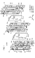
図1に示すように、本発明の第1の実施形態に係る燃料電池スタック10は、発電ユニット12を備え、複数の前記発電ユニット12が、水平方向(矢印A方向)に沿って互いに積層される。
As shown in FIG. 1, the
発電ユニット12は、図1及び図2に示すように、第1セパレータ14、第1電解質膜・電極構造体(電解質・電極構造体)16a、第2セパレータ18、第2電解質膜・電極構造体16b及び第3セパレータ20を設ける。第1セパレータ14、第2セパレータ18及び第3セパレータ20は、例えば、カーボンセパレータや金属セパレータにより構成される。
As shown in FIGS. 1 and 2, the
第1電解質膜・電極構造体16aは、第2電解質膜・電極構造体16bよりも小さな表面積に設定される。第1及び第2電解質膜・電極構造体16a、16bは、例えば、パーフルオロスルホン酸の薄膜に水が含浸された固体高分子電解質膜22と、前記固体高分子電解質膜22を挟持するアノード側電極24及びカソード側電極26とを備える。アノード側電極24は、カソード側電極26よりも小さな表面積を有する段差型MEAを構成している。
The first electrolyte membrane /
アノード側電極24及びカソード側電極26は、カーボンペーパ等からなるガス拡散層(図示せず)と、白金合金が表面に担持された多孔質カーボン粒子が前記ガス拡散層の表面に一様に塗布されて形成される電極触媒層(図示せず)とを有する。電極触媒層は、固体高分子電解質膜22の両面に形成される。
The
図1に示すように、発電ユニット12の長辺方向(矢印C方向)の上端縁部には、矢印A方向に互いに連通して、酸化剤ガス、例えば、酸素含有ガスを供給するための酸化剤ガス入口連通孔30a、及び燃料ガス、例えば、水素含有ガスを供給するための燃料ガス入口連通孔32aが設けられる。
As shown in FIG. 1, the upper end edge of the
発電ユニット12の長辺方向(矢印C方向)の下端縁部には、矢印A方向に互いに連通して、燃料ガスを排出するための燃料ガス出口連通孔32b、及び酸化剤ガスを排出するための酸化剤ガス出口連通孔30bが設けられる。
The lower end edge of the long side direction (arrow C direction) of the
発電ユニット12の短辺方向(矢印B方向)の両端縁部上方には、矢印A方向に互いに連通して、冷却媒体を供給するための一対の冷却媒体入口連通孔34a、34aが設けられるとともに、前記発電ユニット12の短辺方向の両端縁部下方には、前記冷却媒体を排出するための一対の冷却媒体出口連通孔34b、34bが設けられる。
A pair of cooling medium
各冷却媒体入口連通孔34a、34aは、酸化剤ガス入口連通孔30a及び燃料ガス入口連通孔32aに近接し、且つそれぞれ矢印B方向両側の各辺に振り分けられる。各冷却媒体出口連通孔34b、34bは、酸化剤ガス出口連通孔30b及び燃料ガス出口連通孔32bにそれぞれ近接し、且つそれぞれ矢印B方向両側の各辺に振り分けられる。
Each cooling medium
冷却媒体入口連通孔34a、34aの間には、後述する冷却媒体流路44に連通し且つ積層方向に貫通して入口側補助連通孔35aが設けられる。冷却媒体出口連通孔34b、34bの間、好ましくは、冷却媒体流路44の幅方向の略中央部には、後述する冷却媒体流路44に連通し且つ積層方向に貫通して出口側補助連通孔35bが設けられる。なお、第1の実施形態では、入口側補助連通孔35a及び出口側補助連通孔35bの中、少なくとも出口側補助連通孔35bを設けるだけでもよい。
Between the cooling medium
図1に示すように、第1セパレータ14の第1電解質膜・電極構造体16aに向かう面14aには、燃料ガス入口連通孔32aと燃料ガス出口連通孔32bとを連通する第1燃料ガス流路36が形成される。第1燃料ガス流路36は、矢印C方向に延在する複数の流路溝部36aを有するとともに、前記第1燃料ガス流路36の入口近傍及び出口近傍には、それぞれ複数のエンボスを有する入口バッファ部38及び出口バッファ部40が設けられる。
As shown in FIG. 1, the first fuel gas flow that communicates the fuel gas
第1セパレータ14の面14bには、冷却媒体入口連通孔34aと冷却媒体出口連通孔34bとを連通する冷却媒体流路44の一部である複数の流路溝部44aが形成される。流路溝部44aの入口近傍及び出口近傍には、それぞれ複数のエンボスを有する入口バッファ部46a及び出口バッファ部48aが設けられる。
On the
第2セパレータ18の第1電解質膜・電極構造体16aに向かう面18aには、酸化剤ガス入口連通孔30aと酸化剤ガス出口連通孔30bとを連通する第1酸化剤ガス流路50が形成される。第1酸化剤ガス流路50は、矢印C方向に延在する複数の流路溝部50aを有する。第1酸化剤ガス流路50の入口近傍及び出口近傍には、入口バッファ部52及び出口バッファ部54が設けられる。
A first oxidant
第2セパレータ18の第2電解質膜・電極構造体16bに向かう面18bには、燃料ガス入口連通孔32aと燃料ガス出口連通孔32bとを連通する第2燃料ガス流路58が形成される。第2燃料ガス流路58は、矢印C方向に延在する複数の流路溝部58aを有するとともに、前記第2燃料ガス流路58の入口近傍及び出口近傍には、入口バッファ部60及び出口バッファ部62が設けられる。
A second fuel
第3セパレータ20の第2電解質膜・電極構造体16bに向かう面20aには、酸化剤ガス入口連通孔30aと酸化剤ガス出口連通孔30bとを連通する第2酸化剤ガス流路66が形成される。第2酸化剤ガス流路66は、矢印C方向に延在する複数の流路溝部66aを有する。第2酸化剤ガス流路66の入口近傍及び出口近傍には、入口バッファ部68及び出口バッファ部70が設けられる。
A second oxidant gas flow channel 66 that connects the oxidant gas
第3セパレータ20の面20bには、冷却媒体流路44の一部である複数の流路溝部44bが形成される。流路溝部44bの入口近傍及び出口近傍には、それぞれ複数のエンボスを有する入口バッファ部46b及び出口バッファ部48bが設けられる。
A plurality of
図1及び図2に示すように、第1セパレータ14の面14a、14bには、この第1セパレータ14の外周端縁部を周回して第1シール部材74が、個別に又は一体に設けられる。第2セパレータ18の面18a、18bには、この第2セパレータ18の外周端縁部を周回して第2シール部材76が、個別に又は一体に設けられるとともに、第3セパレータ20の面20a、20bには、この第3セパレータ20の外周端縁部を周回して第3シール部材78が、個別に又は一体に設けられる。
As shown in FIGS. 1 and 2,
図3に示すように、第1セパレータ14の面14bでは、第1シール部材74は、冷却媒体入口連通孔34a、34a及び入口側補助連通孔35aを、冷却媒体流路44の入口側に連通する一方、冷却媒体出口連通孔34b、34b及び出口側補助連通孔35bを、前記冷却媒体流路44の出口側に連通する。
As shown in FIG. 3, on the
同様に、第3セパレータ20の面20bでは、図1に示すように、第3シール部材78は、冷却媒体入口連通孔34a、34a及び入口側補助連通孔35aを、冷却媒体流路44の入口側に連通する一方、冷却媒体出口連通孔34b、34b及び出口側補助連通孔35bを、前記冷却媒体流路44の出口側に連通する。
Similarly, on the
第1セパレータ14は、燃料ガス入口連通孔32aと第1燃料ガス流路36とを連通する複数の外側供給孔部80a及び内側供給孔部80bと、燃料ガス出口連通孔32bと前記第1燃料ガス流路36とを連通する複数の外側排出孔部82a及び内側排出孔部82bとを有する。
The
第2セパレータ18は、燃料ガス入口連通孔32aと第2燃料ガス流路58とを連通する複数の供給孔部84と、燃料ガス出口連通孔32bと前記第2燃料ガス流路58とを連通する複数の排出孔部86とを有する。
The
発電ユニット12同士が互いに積層されることにより、一方の発電ユニット12を構成する第1セパレータ14と、他方の発電ユニット12を構成する第3セパレータ20との間には、矢印B方向に延在する冷却媒体流路44が形成される。
When the
このように構成される燃料電池スタック10の動作について、以下に説明する。
The operation of the
先ず、図1に示すように、酸化剤ガス入口連通孔30aには、酸素含有ガス等の酸化剤ガスが供給されるとともに、燃料ガス入口連通孔32aには、水素含有ガス等の燃料ガスが供給される。さらに、一対の冷却媒体入口連通孔34a、34a及び入口側補助連通孔35aには、純水やエチレングリコール、オイル等の冷却媒体が供給される。
First, as shown in FIG. 1, an oxidant gas such as an oxygen-containing gas is supplied to the oxidant gas
このため、酸化剤ガスは、酸化剤ガス入口連通孔30aから第2セパレータ18の第1酸化剤ガス流路50及び第3セパレータ20の第2酸化剤ガス流路66に導入される。この酸化剤ガスは、第1酸化剤ガス流路50に沿って矢印C方向(重力方向)に移動し、第1電解質膜・電極構造体16aのカソード側電極26に供給されるとともに、第2酸化剤ガス流路66に沿って矢印C方向に移動し、第2電解質膜・電極構造体16bのカソード側電極26に供給される。
Therefore, the oxidant gas is introduced into the first
一方、燃料ガスは、図2に示すように、燃料ガス入口連通孔32aから外側供給孔部80aを通って第1セパレータ14の面14b側に移動する。さらに、燃料ガスは、内側供給孔部80bから面14a側に導入された後、第1燃料ガス流路36に沿って重力方向(矢印C方向)に移動し、第1電解質膜・電極構造体16aのアノード側電極24に供給される(図1参照)。
On the other hand, as shown in FIG. 2, the fuel gas moves from the fuel gas
また、燃料ガスは、図2に示すように、供給孔部84を通って第2セパレータ18の面18b側に移動する。このため、図1に示すように、燃料ガスは、面18b側で第2燃料ガス流路58に沿って矢印C方向に移動し、第2電解質膜・電極構造体16bのアノード側電極24に供給される。
Further, as shown in FIG. 2, the fuel gas moves to the
従って、第1及び第2電解質膜・電極構造体16a、16bでは、カソード側電極26に供給される酸化剤ガスと、アノード側電極24に供給される燃料ガスとが、電極触媒層内で電気化学反応により消費されて発電が行われる。
Therefore, in the first and second electrolyte membrane /
次いで、第1及び第2電解質膜・電極構造体16a、16bの各カソード側電極26に供給されて消費された酸化剤ガスは、酸化剤ガス出口連通孔30bに沿って矢印A方向に排出される。
Next, the oxidant gas consumed by being supplied to the cathode-
第1電解質膜・電極構造体16aのアノード側電極24に供給されて消費された燃料ガスは、内側排出孔部82bを通って第1セパレータ14の面14b側に導出される。面14b側に導出された燃料ガスは、外側排出孔部82aを通って、再度、面14a側に移動し、燃料ガス出口連通孔32bに排出される。
The fuel gas consumed by being supplied to the
また、第2電解質膜・電極構造体16bのアノード側電極24に供給されて消費された燃料ガスは、排出孔部86を通って面18a側に移動する。この燃料ガスは、燃料ガス出口連通孔32bに排出される。
Further, the fuel gas consumed by being supplied to the
一方、左右一対の冷却媒体入口連通孔34a、34a及び入口側補助連通孔35aに供給された冷却媒体は、図1に示すように、一方の発電ユニット12を構成する第1セパレータ14と、他方の発電ユニット12を構成する第3セパレータ20との間に形成された冷却媒体流路44に導入される。
On the other hand, as shown in FIG. 1, the cooling medium supplied to the pair of left and right cooling medium
図3に示すように、一対の冷却媒体入口連通孔34a、34aは、発電ユニット12の上部側左右両端に酸化剤ガス入口連通孔30a及び燃料ガス入口連通孔32aに近接する位置に振り分けて設けられている。
As shown in FIG. 3, the pair of cooling medium inlet communication holes 34 a, 34 a are provided at the left and right ends of the upper side of the
このため、各冷却媒体入口連通孔34a、34aから冷却媒体流路44に供給される冷却媒体は、矢印B方向に且つ互いに近接する方向に供給される。そして、互いに近接する冷却媒体は、冷却媒体流路44の矢印B方向中央部側で衝突して重力方向(矢印C方向下方)に移動した後、発電ユニット12の下部側両側部に振り分けて設けられている各冷却媒体出口連通孔34b、34bに排出される。
For this reason, the cooling medium supplied from the cooling medium
この場合、第1の実施形態では、冷却媒体入口連通孔34a、34a間に設けられている入口側補助連通孔35aから供給される冷却媒体は、冷却媒体流路44の矢印B方向中央部側に導入される。従って、冷却媒体流路44の入口側では、冷却媒体の矢印B方向の入口側合流部位P1(図3参照)に、入口側補助連通孔35aから重力方向に前記冷却媒体が供給されている。これにより、冷却媒体が流れ難い入口側合流部位P1における前記冷却媒体の流配性が向上し、前記入口側合流部位P1に局部的に高温になる部位(ヒートスポット)が惹起されることを阻止することができる。
In this case, in the first embodiment, the cooling medium supplied from the inlet side
しかも、第1の実施形態では、冷却媒体流路44の出口側に流動した冷却媒体は、冷却媒体出口連通孔34b、34bに振り分け排出されるとともに、前記冷却媒体出口連通孔34b、34b間に設けられている出口側補助連通孔35bに排出されている(図3参照)。
Moreover, in the first embodiment, the cooling medium that has flowed to the outlet side of the cooling
このため、冷却媒体流路44の出口側では、冷却媒体が出口側合流部位P2から出口側補助連通孔35bに向かって重力方向に排出されている。従って、冷却媒体が流れ難い出口側合流部位P2における冷却媒体の流配性が向上し、前記出口側合流部位P2に局部的に高温になる部位(ヒートスポット)が惹起されることを阻止することが可能になる。
For this reason, on the outlet side of the cooling
特に、冷却媒体流路44における冷却媒体の流れは、第1及び第2燃料ガス流路36、58の燃料ガスの流れや第1及び第2酸化剤ガス流路50、66の酸化剤ガスの流れと、並行流れ(重力流れ)に設定されている。その際、冷却媒体の下流部は、燃料ガスの下流部及び酸化剤ガスの下流部と一致するため、該下流部(出口側合流部位P2)が高温になり易い。
In particular, the flow of the cooling medium in the cooling
これにより、冷却媒体出口連通孔34b、34b間に出口側補助連通孔35bを設けることによって、出口側合流部位P2での流配性が良好に向上し、簡単な構成で、発電機能に必要な冷却性能を確保することが可能になるという効果が得られる。
Thus, by providing the outlet side
また、冷却媒体流路44を流れる冷却媒体は、第2酸化剤ガス流路66を流れる酸化剤ガスの流れに対して並行(重力方向)に設定されている。従って、第2酸化剤ガス流路66の上流部における冷却媒体流量の増加に伴う高加湿領域が拡大され、抵抗過電圧が低減する。
The cooling medium flowing through the cooling
一方、第2酸化剤ガス流路66(及び第1酸化剤ガス流路50)の下流部側では、加温された冷却媒体が供給されて生成水の水蒸気化が促進され、フラッディングの抑制による濃度過電圧の低減が図られる。このため、発電ユニット12内での出力及び耐久性が向上するとともに、第2酸化剤ガス流路66(及び第1酸化剤ガス流路50)の上流側から下流側における湿度環境の均一化が図られ、固体高分子電解質膜22の含水による膨張が均一化されて、スタック撓みの抑制が遂行される。
On the other hand, on the downstream side of the second oxidant gas flow channel 66 (and the first oxidant gas flow channel 50), a heated cooling medium is supplied to promote water vaporization of the generated water, thereby suppressing flooding. Concentration overvoltage can be reduced. Therefore, the output and durability in the
図4は、本発明の第2の実施形態に係る燃料電池スタック90を構成する発電ユニット92の要部分解斜視説明図である。
FIG. 4 is an exploded perspective view of the main part of the
なお、第1の実施形態に係る発電ユニット12と同一の構成要素には同一の参照符号を付して、その詳細な説明は省略する。また、以下に説明する第3の実施形態においても同様に、その詳細な説明は省略する。
In addition, the same referential mark is attached | subjected to the component same as the electric
発電ユニット92は、第1セパレータ94、電解質膜・電極構造体(電解質・電極構造体)96及び第2セパレータ98を備える。第1セパレータ94及び第2セパレータ98は、例えば、カーボンセパレータや金属セパレータにより構成される。
The
第1セパレータ94の面14aには、第1燃料ガス流路36が形成されるとともに、面14bには、冷却媒体流路44を構成する流路溝部44aが形成される。第2セパレータ98の面20aには、第1酸化剤ガス流路50が形成されるとともに、面20bには、冷却媒体流路44を構成する流路溝部44bが形成される。各発電ユニット92毎に、冷却媒体流路44が形成される。
A first
電解質膜・電極構造体96は、固体高分子電解質膜22aと、前記固体高分子電解質膜22aを挟持するアノード側電極24a及びカソード側電極26aとを備える。
The electrolyte membrane /
このように構成される第2の実施形態では、冷却媒体出口連通孔34b、34b間に出口側補助連通孔35bが設けられる一方、必要に応じて、冷却媒体入口連通孔34a、34a間に入口側補助連通孔35aが設けられている。
In the second embodiment configured as described above, the outlet side
従って、出口側合流部位P2及び入口側合流部位P1における冷却媒体の流配性が向上し、前記出口側合流部位P2及び前記入口側合流部位P1に局部的に高温になる部位(ヒートスポット)が惹起されることを阻止することができる等、上記の第1の実施形態と同様の効果が得られる。 Therefore, the flow distribution of the cooling medium at the outlet side merging portion P2 and the inlet side merging portion P1 is improved, and a portion (heat spot) that locally becomes high in the outlet side merging portion P2 and the inlet side merging portion P1. The same effects as those of the first embodiment described above can be obtained, such as being able to prevent inducing.
図5は、本発明の第3の実施形態に係る燃料電池スタック100を構成する発電ユニット102の要部分解斜視説明図である。
FIG. 5 is an exploded perspective view of the main part of the
発電ユニット102は、第1セパレータ104、第1電解質膜・電極構造体(電解質・電極構造体)16a、第2セパレータ106、第2電解質膜・電極構造体16b及び第3セパレータ108を設ける。
The
第1セパレータ104の第1電解質膜・電極構造体16aに向かう面14aには、第1燃料ガス流路36が形成される。第1燃料ガス流路36は、矢印C方向に延在する複数の波形状流路溝部110を有する。第1セパレータ104の面14bには、冷却媒体流路44の一部である複数の波形状流路溝部112aが形成される。
A first fuel
第2セパレータ106の第1電解質膜・電極構造体16aに向かう面18aには、第1酸化剤ガス流路50が形成される。第1酸化剤ガス流路50は、矢印C方向に延在する複数の波形状流路溝部114を有する。第2セパレータ106の第2電解質膜・電極構造体16bに向かう面18bには、第2燃料ガス流路58が形成される。第2燃料ガス流路58は、矢印C方向に延在する複数の波形状流路溝部116を有する。
A first oxidant
第3セパレータ108の第2電解質膜・電極構造体16bに向かう面20aには、酸化剤ガス入口連通孔30aと酸化剤ガス出口連通孔30bとを連通する第2酸化剤ガス流路66が形成される。第2酸化剤ガス流路66は、矢印C方向に延在する複数の波形状流路溝部118を有する。第3セパレータ108の面20bには、冷却媒体流路44の一部である複数の流路溝部112bが形成される。
A second oxidant gas flow channel 66 that connects the oxidant gas
このように構成される第3の実施形態では、出口側合流部位P2及び入口側合流部位P1における冷却媒体の流配性が向上し、前記出口側合流部位P2及び前記入口側合流部位P1に局部的に高温になる部位(ヒートスポット)が惹起されることを阻止することができる等、上記の第1及び第2の実施形態と同様の効果が得られる。 In the third embodiment configured as described above, the flowability of the cooling medium at the outlet-side merging site P2 and the inlet-side merging site P1 is improved, and the outlet side merging site P2 and the inlet-side merging site P1 are locally provided. Thus, the same effects as those of the first and second embodiments can be obtained, for example, it is possible to prevent the occurrence of a site (heat spot) that becomes high in temperature.
10、90、100…燃料電池スタック
12、92、102…発電ユニット
14、18、20、94、98、104、106、108…セパレータ
16a、16b、96…電解質膜・電極構造体
22、22a…固体高分子電解質膜 24、24a…アノード側電極
26、26a…カソード側電極 30a…酸化剤ガス入口連通孔
30b…酸化剤ガス出口連通孔 32a…燃料ガス入口連通孔
32b…燃料ガス出口連通孔 34a…冷却媒体入口連通孔
34b…冷却媒体出口連通孔 35a…入口側補助連通孔
35b…出口側補助連通孔 36、58…燃料ガス流路
38、46a、46b、52、60、68…入口バッファ部
40、48a、48b、54、62、70…出口バッファ部
44…冷却媒体流路 50、66…酸化剤ガス流路
10, 90, 100 ... fuel cell stacks 12, 92, 102 ...
Claims (4)
前記セパレータの互いに対向する一方の2辺には、それぞれ各辺に振り分けられて前記冷却媒体を流すための一対の冷却媒体入口連通孔及び一対の冷却媒体出口連通孔が、積層方向に貫通して設けられるとともに、
少なくとも一対の前記冷却媒体出口連通孔の間には、前記冷却媒体流路に連通し且つ前記積層方向に貫通して補助連通孔が設けられることを特徴とする燃料電池スタック。 An electrolyte / electrode structure provided with a pair of electrodes on both sides of the electrolyte and a separator are stacked, and a reaction gas that is a fuel gas or an oxidant gas is supplied along the electrodes to the electrode facing surface of the separator A fuel cell stack including a power generation unit provided with a reaction gas flow path, forming a cooling medium flow path for circulating a cooling medium between the power generation units, and laminating the power generation units to each other,
A pair of cooling medium inlet communication holes and a pair of cooling medium outlet communication holes, which are distributed to the respective sides and flow the cooling medium, pass through in the stacking direction on the two opposite sides of the separator. As well as
An auxiliary communication hole is provided between at least a pair of the cooling medium outlet communication holes and communicates with the cooling medium flow path and penetrates in the stacking direction.
前記セパレータの長辺の一端側に、前記反応ガス入口連通孔である酸化剤ガス入口連通孔及び燃料ガス入口連通孔が設けられ、
前記セパレータの長辺の他端側に、前記反応ガス出口連通孔である酸化剤ガス出口連通孔及び燃料ガス出口連通孔が設けられるとともに、
前記セパレータの前記酸化剤ガス入口連通孔及び前記燃料ガス入口連通孔の近傍に、一対の前記冷却媒体入口連通孔又は一対の前記冷却媒体出口連通孔が短辺方向に振り分けて設けられ、
前記セパレータの前記酸化剤ガス出口連通孔及び前記燃料ガス出口連通孔の近傍に、一対の前記冷却媒体出口連通孔又は一対の前記冷却媒体入口連通孔が短辺方向に振り分けて設けられることを特徴とする燃料電池スタック。 The fuel cell stack according to claim 1 or 2, wherein the separator has a rectangular shape,
An oxidant gas inlet communication hole and a fuel gas inlet communication hole, which are the reaction gas inlet communication holes, are provided on one end side of the long side of the separator,
On the other end side of the long side of the separator, an oxidant gas outlet communication hole and a fuel gas outlet communication hole which are the reaction gas outlet communication holes are provided,
In the vicinity of the oxidant gas inlet communication hole and the fuel gas inlet communication hole of the separator, a pair of the cooling medium inlet communication holes or a pair of the cooling medium outlet communication holes are provided in the short side direction.
A pair of cooling medium outlet communication holes or a pair of cooling medium inlet communication holes are provided in the vicinity of the oxidant gas outlet communication hole and the fuel gas outlet communication hole of the separator so as to be distributed in the short side direction. And fuel cell stack.
前記補助連通孔は、前記バッファ部に形成されることを特徴とする燃料電池スタック。 The fuel cell stack according to any one of claims 1 to 3, wherein a buffer unit communicates with an inlet side and an outlet side of the cooling medium flow path, respectively.
The fuel cell stack, wherein the auxiliary communication hole is formed in the buffer portion.
Priority Applications (1)
| Application Number | Priority Date | Filing Date | Title |
|---|---|---|---|
| JP2009137307A JP5265455B2 (en) | 2009-06-08 | 2009-06-08 | Fuel cell stack |
Applications Claiming Priority (1)
| Application Number | Priority Date | Filing Date | Title |
|---|---|---|---|
| JP2009137307A JP5265455B2 (en) | 2009-06-08 | 2009-06-08 | Fuel cell stack |
Publications (2)
| Publication Number | Publication Date |
|---|---|
| JP2010282931A true JP2010282931A (en) | 2010-12-16 |
| JP5265455B2 JP5265455B2 (en) | 2013-08-14 |
Family
ID=43539487
Family Applications (1)
| Application Number | Title | Priority Date | Filing Date |
|---|---|---|---|
| JP2009137307A Expired - Fee Related JP5265455B2 (en) | 2009-06-08 | 2009-06-08 | Fuel cell stack |
Country Status (1)
| Country | Link |
|---|---|
| JP (1) | JP5265455B2 (en) |
Cited By (1)
| Publication number | Priority date | Publication date | Assignee | Title |
|---|---|---|---|---|
| US9350029B2 (en) | 2012-11-21 | 2016-05-24 | Honda Motor Co., Ltd. | Fuel cell stack |
Citations (6)
| Publication number | Priority date | Publication date | Assignee | Title |
|---|---|---|---|---|
| JP2003157865A (en) * | 2001-11-19 | 2003-05-30 | Honda Motor Co Ltd | Fuel cell stack |
| JP2003323905A (en) * | 2002-02-26 | 2003-11-14 | Honda Motor Co Ltd | Solid polymer fuel cell |
| JP2004186139A (en) * | 2002-11-20 | 2004-07-02 | Honda Motor Co Ltd | Fuel cell |
| JP2007066644A (en) * | 2005-08-30 | 2007-03-15 | Nok Corp | Fuel cell |
| JP2007514286A (en) * | 2003-12-15 | 2007-05-31 | エリオン | Feed plate for fuel cells with co-circulation |
| JP2007141553A (en) * | 2005-11-16 | 2007-06-07 | Honda Motor Co Ltd | Fuel cell stack |
-
2009
- 2009-06-08 JP JP2009137307A patent/JP5265455B2/en not_active Expired - Fee Related
Patent Citations (6)
| Publication number | Priority date | Publication date | Assignee | Title |
|---|---|---|---|---|
| JP2003157865A (en) * | 2001-11-19 | 2003-05-30 | Honda Motor Co Ltd | Fuel cell stack |
| JP2003323905A (en) * | 2002-02-26 | 2003-11-14 | Honda Motor Co Ltd | Solid polymer fuel cell |
| JP2004186139A (en) * | 2002-11-20 | 2004-07-02 | Honda Motor Co Ltd | Fuel cell |
| JP2007514286A (en) * | 2003-12-15 | 2007-05-31 | エリオン | Feed plate for fuel cells with co-circulation |
| JP2007066644A (en) * | 2005-08-30 | 2007-03-15 | Nok Corp | Fuel cell |
| JP2007141553A (en) * | 2005-11-16 | 2007-06-07 | Honda Motor Co Ltd | Fuel cell stack |
Cited By (1)
| Publication number | Priority date | Publication date | Assignee | Title |
|---|---|---|---|---|
| US9350029B2 (en) | 2012-11-21 | 2016-05-24 | Honda Motor Co., Ltd. | Fuel cell stack |
Also Published As
| Publication number | Publication date |
|---|---|
| JP5265455B2 (en) | 2013-08-14 |
Similar Documents
| Publication | Publication Date | Title |
|---|---|---|
| JP5054150B2 (en) | Fuel cell stack | |
| JP4753599B2 (en) | Fuel cell | |
| JP5180484B2 (en) | Fuel cell stack | |
| JP5962847B2 (en) | FUEL CELL, FUEL CELL DISTRIBUTION DEVICE, AND VEHICLE HAVING FUEL CELL | |
| JP5123279B2 (en) | Fuel cell | |
| JP2009043493A (en) | Fuel cell stack | |
| JP2011054404A (en) | Fuel cell | |
| JP2009009837A (en) | Fuel cell | |
| JP2009059513A (en) | Fuel cell | |
| JP5449838B2 (en) | Fuel cell stack | |
| JP2006236612A (en) | Fuel cell | |
| JP2006278177A (en) | Fuel cell | |
| JP2009043665A (en) | Fuel cell | |
| JP5054082B2 (en) | Fuel cell stack | |
| JP2007226991A (en) | Fuel cell | |
| JP2011119061A (en) | Fuel cell | |
| JP4185734B2 (en) | Fuel cell stack | |
| JP5265455B2 (en) | Fuel cell stack | |
| JP5714432B2 (en) | Fuel cell stack | |
| JP4516630B2 (en) | Solid polymer cell assembly | |
| JP4572252B2 (en) | Fuel cell stack | |
| JP5123824B2 (en) | FUEL CELL STACK AND METHOD OF OPERATING FUEL CELL STACK | |
| JP5283520B2 (en) | Fuel cell stack | |
| JP2010003541A (en) | Fuel cell stack | |
| JP5336221B2 (en) | Fuel cell stack |
Legal Events
| Date | Code | Title | Description |
|---|---|---|---|
| A977 | Report on retrieval |
Free format text: JAPANESE INTERMEDIATE CODE: A971007 Effective date: 20121024 |
|
| A131 | Notification of reasons for refusal |
Free format text: JAPANESE INTERMEDIATE CODE: A131 Effective date: 20121106 |
|
| A521 | Request for written amendment filed |
Free format text: JAPANESE INTERMEDIATE CODE: A523 Effective date: 20121225 |
|
| A131 | Notification of reasons for refusal |
Free format text: JAPANESE INTERMEDIATE CODE: A131 Effective date: 20130122 |
|
| A521 | Request for written amendment filed |
Free format text: JAPANESE INTERMEDIATE CODE: A523 Effective date: 20130313 |
|
| TRDD | Decision of grant or rejection written | ||
| A01 | Written decision to grant a patent or to grant a registration (utility model) |
Free format text: JAPANESE INTERMEDIATE CODE: A01 Effective date: 20130402 |
|
| A61 | First payment of annual fees (during grant procedure) |
Free format text: JAPANESE INTERMEDIATE CODE: A61 Effective date: 20130501 |
|
| R150 | Certificate of patent or registration of utility model |
Free format text: JAPANESE INTERMEDIATE CODE: R150 Ref document number: 5265455 Country of ref document: JP Free format text: JAPANESE INTERMEDIATE CODE: R150 |
|
| LAPS | Cancellation because of no payment of annual fees |