JP2010281322A - Fuel injection method for direct injection internal combustion engine - Google Patents
Fuel injection method for direct injection internal combustion engine Download PDFInfo
- Publication number
- JP2010281322A JP2010281322A JP2010127862A JP2010127862A JP2010281322A JP 2010281322 A JP2010281322 A JP 2010281322A JP 2010127862 A JP2010127862 A JP 2010127862A JP 2010127862 A JP2010127862 A JP 2010127862A JP 2010281322 A JP2010281322 A JP 2010281322A
- Authority
- JP
- Japan
- Prior art keywords
- fuel
- injection
- injections
- injection method
- combustion
- Prior art date
- Legal status (The legal status is an assumption and is not a legal conclusion. Google has not performed a legal analysis and makes no representation as to the accuracy of the status listed.)
- Withdrawn
Links
Images

Classifications
-
- F—MECHANICAL ENGINEERING; LIGHTING; HEATING; WEAPONS; BLASTING
- F02—COMBUSTION ENGINES; HOT-GAS OR COMBUSTION-PRODUCT ENGINE PLANTS
- F02D—CONTROLLING COMBUSTION ENGINES
- F02D41/00—Electrical control of supply of combustible mixture or its constituents
- F02D41/30—Controlling fuel injection
- F02D41/38—Controlling fuel injection of the high pressure type
- F02D41/40—Controlling fuel injection of the high pressure type with means for controlling injection timing or duration
- F02D41/402—Multiple injections
-
- F—MECHANICAL ENGINEERING; LIGHTING; HEATING; WEAPONS; BLASTING
- F02—COMBUSTION ENGINES; HOT-GAS OR COMBUSTION-PRODUCT ENGINE PLANTS
- F02B—INTERNAL-COMBUSTION PISTON ENGINES; COMBUSTION ENGINES IN GENERAL
- F02B23/00—Other engines characterised by special shape or construction of combustion chambers to improve operation
- F02B23/02—Other engines characterised by special shape or construction of combustion chambers to improve operation with compression ignition
- F02B23/06—Other engines characterised by special shape or construction of combustion chambers to improve operation with compression ignition the combustion space being arranged in working piston
- F02B23/0672—Omega-piston bowl, i.e. the combustion space having a central projection pointing towards the cylinder head and the surrounding wall being inclined towards the cylinder center axis
-
- F—MECHANICAL ENGINEERING; LIGHTING; HEATING; WEAPONS; BLASTING
- F02—COMBUSTION ENGINES; HOT-GAS OR COMBUSTION-PRODUCT ENGINE PLANTS
- F02F—CYLINDERS, PISTONS OR CASINGS, FOR COMBUSTION ENGINES; ARRANGEMENTS OF SEALINGS IN COMBUSTION ENGINES
- F02F3/00—Pistons
- F02F3/10—Pistons having surface coverings
- F02F3/12—Pistons having surface coverings on piston heads
- F02F3/14—Pistons having surface coverings on piston heads within combustion chambers
-
- F—MECHANICAL ENGINEERING; LIGHTING; HEATING; WEAPONS; BLASTING
- F02—COMBUSTION ENGINES; HOT-GAS OR COMBUSTION-PRODUCT ENGINE PLANTS
- F02B—INTERNAL-COMBUSTION PISTON ENGINES; COMBUSTION ENGINES IN GENERAL
- F02B23/00—Other engines characterised by special shape or construction of combustion chambers to improve operation
- F02B23/02—Other engines characterised by special shape or construction of combustion chambers to improve operation with compression ignition
- F02B23/06—Other engines characterised by special shape or construction of combustion chambers to improve operation with compression ignition the combustion space being arranged in working piston
- F02B23/0603—Other engines characterised by special shape or construction of combustion chambers to improve operation with compression ignition the combustion space being arranged in working piston at least part of the interior volume or the wall of the combustion space being made of material different from the surrounding piston part, e.g. combustion space formed within a ceramic part fixed to a metal piston head
- F02B2023/0612—Other engines characterised by special shape or construction of combustion chambers to improve operation with compression ignition the combustion space being arranged in working piston at least part of the interior volume or the wall of the combustion space being made of material different from the surrounding piston part, e.g. combustion space formed within a ceramic part fixed to a metal piston head the material having a high temperature and pressure resistance, e.g. ceramic
-
- F—MECHANICAL ENGINEERING; LIGHTING; HEATING; WEAPONS; BLASTING
- F05—INDEXING SCHEMES RELATING TO ENGINES OR PUMPS IN VARIOUS SUBCLASSES OF CLASSES F01-F04
- F05C—INDEXING SCHEME RELATING TO MATERIALS, MATERIAL PROPERTIES OR MATERIAL CHARACTERISTICS FOR MACHINES, ENGINES OR PUMPS OTHER THAN NON-POSITIVE-DISPLACEMENT MACHINES OR ENGINES
- F05C2203/00—Non-metallic inorganic materials
- F05C2203/08—Ceramics; Oxides
- F05C2203/0804—Non-oxide ceramics
- F05C2203/083—Nitrides
- F05C2203/0843—Nitrides of silicon
-
- Y—GENERAL TAGGING OF NEW TECHNOLOGICAL DEVELOPMENTS; GENERAL TAGGING OF CROSS-SECTIONAL TECHNOLOGIES SPANNING OVER SEVERAL SECTIONS OF THE IPC; TECHNICAL SUBJECTS COVERED BY FORMER USPC CROSS-REFERENCE ART COLLECTIONS [XRACs] AND DIGESTS
- Y02—TECHNOLOGIES OR APPLICATIONS FOR MITIGATION OR ADAPTATION AGAINST CLIMATE CHANGE
- Y02T—CLIMATE CHANGE MITIGATION TECHNOLOGIES RELATED TO TRANSPORTATION
- Y02T10/00—Road transport of goods or passengers
- Y02T10/10—Internal combustion engine [ICE] based vehicles
- Y02T10/12—Improving ICE efficiencies
-
- Y—GENERAL TAGGING OF NEW TECHNOLOGICAL DEVELOPMENTS; GENERAL TAGGING OF CROSS-SECTIONAL TECHNOLOGIES SPANNING OVER SEVERAL SECTIONS OF THE IPC; TECHNICAL SUBJECTS COVERED BY FORMER USPC CROSS-REFERENCE ART COLLECTIONS [XRACs] AND DIGESTS
- Y02—TECHNOLOGIES OR APPLICATIONS FOR MITIGATION OR ADAPTATION AGAINST CLIMATE CHANGE
- Y02T—CLIMATE CHANGE MITIGATION TECHNOLOGIES RELATED TO TRANSPORTATION
- Y02T10/00—Road transport of goods or passengers
- Y02T10/10—Internal combustion engine [ICE] based vehicles
- Y02T10/40—Engine management systems
Abstract
Description
本発明は、直噴自己着火内燃エンジン、特にディーゼル型のエンジンの燃料噴射方法に関する。 The present invention relates to a fuel injection method for a direct injection self-ignition internal combustion engine, in particular, a diesel engine.
本発明は、特に、燃料混合気の低温燃焼モード、より一般的にはLTC(Low-Temperature Combustion)として知られているモードで動作するディーゼル型のエンジンに関する。 The invention particularly relates to a diesel engine operating in a low temperature combustion mode of a fuel mixture, more commonly known as LTC (Low-Temperature Combustion).
このLTC燃焼形式は、燃焼による汚染物質の生成を抑制すること、特に窒素酸化物(NOx)および粒子の生成を抑制することに特に有利である。 This LTC combustion mode is particularly advantageous for suppressing the production of pollutants by combustion, particularly for suppressing the production of nitrogen oxides (NO x ) and particles.
この燃焼は一般に、燃焼温度を低下させるためにエンジン吸気への大量の排気再循環(EGR)を使用して実施され、これによってNOX排出を低減することができる。その上、混合済みの空気と燃料を高い割合で使用することによって、燃焼前に比較的一様な混合気を得ることができ、生成される粒子を抑制することができる。 This combustion is generally carried out using a large amount of exhaust gas recirculation to the engine intake in order to lower the combustion temperature (EGR), which makes it possible to reduce the NO X emissions. Moreover, by using a high ratio of mixed air and fuel, a relatively uniform air-fuel mixture can be obtained before combustion, and the generated particles can be suppressed.
しかし、この燃焼の形式には、エンジン排気へ排出されるHCの排気が高レベルになるという主な欠点がある。このHCの発生は、HCからCOへ、それからCO2へという総体的な酸化をさせない低燃焼温度に基本的に関連している。 However, this form of combustion has the main drawback that the HC exhaust discharged to the engine exhaust is at a high level. This generation of HC is basically related to the low combustion temperature that does not cause the overall oxidation from HC to CO and then to CO 2 .
特許文献1は、表面がくぼんだボウルを有するピストンが内部で往復直線運動によって摺動するシリンダを備えるようなエンジンについて記述している。例えば、燃料混合気を対象としている燃焼室は、シリンダ壁、ピストンに対向しているシリンダヘッドの表面、このピストンの上側表面、およびボウルの複数の壁によって区切られている。 U.S. Pat. No. 6,057,089 describes an engine in which a piston having a bowl with a concave surface is provided with a cylinder in which it slides by reciprocating linear motion. For example, a combustion chamber intended for a fuel mixture is delimited by a cylinder wall, a cylinder head surface facing the piston, an upper surface of the piston, and a plurality of bowl walls.
前述の特許文献に詳細に説明されているように、エンジンの燃焼室の壁を通した熱損失(この燃料混合気の燃焼時に発生する熱の損失)を最小にしなければならない。したがって、ボウルの複数の表面は少なくとも1部が非常に低い熱伝導率で特に特徴付けられている例えばセラミック類の断熱被覆によって被覆されている。 As explained in detail in the aforementioned patent document, heat loss through the walls of the combustion chamber of the engine (the loss of heat generated during combustion of this fuel mixture) must be minimized. Thus, the surfaces of the bowl are at least partly covered by a thermal barrier coating, for example ceramics, which is particularly characterized by a very low thermal conductivity.
そのため、この被覆は燃料混合気の燃焼時に発生した熱損失を抑制し、これは高い燃焼温度の維持を可能にする。そして、これらの高温レベルは未燃焼炭化水素(HC)と一酸化炭素(CO)とのより良好な酸化の促進を可能にする。さらに、そのような被覆の使用によって、燃焼室の複数の壁の温度が上昇し、この温度上昇は、特にピストン表面に複数の液体燃料の被膜が形成されることを抑制する効果を有する。実際、これらの液体燃料の被膜は、特にLTC燃焼形式ではHCのかなり大きい発生源である。 Therefore, this coating suppresses heat loss that occurs during combustion of the fuel mixture, which allows the high combustion temperature to be maintained. And these high temperature levels allow better promotion of oxidation of unburned hydrocarbons (HC) and carbon monoxide (CO). Furthermore, the use of such a coating raises the temperature of the walls of the combustion chamber, and this temperature rise has the effect of suppressing the formation of a plurality of liquid fuel coatings on the piston surface. In fact, these liquid fuel coatings are a significant source of HC, especially in the LTC combustion mode.
しかし、この温度上昇は、燃料混合気の自己着火遅れ期間の減少や、燃焼速度の上昇など、燃焼に対して有害な欠点につながる。これらの、高いピークのエネルギー放出に一般に至らしめる過度の燃焼速度は、高レベルの燃焼ノイズ(つまりエンジンノイズ)が伴うという不利がある。 However, this temperature rise leads to disadvantages that are harmful to combustion, such as a decrease in the self-ignition delay period of the fuel mixture and an increase in the combustion speed. These excessive burn rates that generally lead to high peak energy emissions are disadvantageous with high levels of combustion noise (ie engine noise).
本発明は、燃焼ノイズのレベルを減少させることができる燃料噴射方法によって、前述の欠点を克服することを目的にしている。 The present invention aims to overcome the aforementioned drawbacks by a fuel injection method that can reduce the level of combustion noise.
本発明は、シリンダヘッドによって閉鎖されているシリンダと、丸くへこんだ部分を有するピストンと、燃料インジェクタとを有する直噴内燃エンジン、特にディーゼル型の直噴内燃エンジンの燃料噴射方法であって、燃料混合気の低温燃焼を行うように、短い間隔で連続している少なくとも2回の連続噴射により、断熱被覆によって被覆されている丸くへこんだ部分の中へ燃料を供給することを特徴とする燃料噴射方法に関する。 The present invention relates to a fuel injection method for a direct injection internal combustion engine, in particular a diesel type direct injection internal combustion engine, having a cylinder closed by a cylinder head, a piston having a rounded recess, and a fuel injector. Fuel injection characterized in that fuel is fed into a rounded depression covered by a thermal barrier coating by at least two successive injections that are continuous at short intervals so as to perform low temperature combustion of the mixture Regarding the method.
本方法は、ある噴射の終了から次の噴射の開始までの1°から10°の間の範囲のクランク軸回転角度に相当している遅れ期間を伴った連続的な噴射で燃料を導入してもよい。 This method introduces fuel in a continuous injection with a delay period corresponding to a crankshaft rotation angle ranging from 1 ° to 10 ° from the end of one injection to the start of the next injection. Also good.
本方法は、同じ量の燃料を連続的な複数回の噴射で導入してもよい。 The method may introduce the same amount of fuel in successive multiple injections.
本方法は、異なる量の燃料を連続的な複数回の噴射で導入してもよい。 The method may introduce different amounts of fuel in successive multiple injections.
本方法は、燃料を、燃料の量を増加させながら連続的な複数回の噴射で導入してもよい。 The method may introduce the fuel in successive multiple injections while increasing the amount of fuel.
本方法は、燃料を、燃料の量を減少させながら連続的な複数回の噴射で導入してもよい。 The method may introduce the fuel in successive multiple injections while reducing the amount of fuel.
本方法は、燃料を連続的な複数回の噴射で、それらの燃料の総量の5%から50%の間の範囲の量で導入してもよい。 The method may introduce fuel in successive multiple injections in an amount ranging between 5% and 50% of the total amount of those fuels.
本発明のその他の特徴と利点は、添付の図面を参照して、非限定的な例によって説明する以降の説明を読むことで明らかになろう。 Other features and advantages of the present invention will become apparent upon reading the following description, given by way of non-limiting example, with reference to the accompanying drawings.
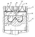
図1は、部分的な局所断面において、低温燃焼モードで動作する自己着火直噴内燃エンジンを示している。このエンジンはディーゼル型であることが好ましいが、ガソリンや気体燃料(VNG、LPG等)を使用するエンジンなどの他の種類のエンジンを決して除外するものではない。 FIG. 1 shows a self-igniting direct injection internal combustion engine operating in a low-temperature combustion mode in a partial local section. This engine is preferably of the diesel type, but does not exclude other types of engines such as engines using gasoline or gaseous fuel (VNG, LPG, etc.).
このエンジンは、クランク軸(不図示)に結合されている連接棒14の作用の下で往復直動運動でピストン12が内部を摺動する少なくとも1つのシリンダ10と、シリンダ10の上部を閉鎖しているシリンダヘッド16とを有している。
This engine closes at least one
ピストン12の上部は凹状のボウル(丸くへこんだ部分)18を有しており、該ボウルは、ピストン12の上側表面20、ショルダ24経由で上側表面20に繋がっている横向きの面22、およびボウル底部26によって境界を定めている。シリンダヘッド16の方向へ突き出している突起28がこのボウル18内にあることが好ましい。概ね先端を切った形状のこの突起28は、このボウル18の実質的に中心に配置されている。この突起28の丸くなった先端30がボウル底部26の方向へ、実質的に直線状の傾斜した側腹32と、側腹32をボウル底部26と横向きの面22とに接続している曲線部分34とによって延びている。
The upper portion of the
このボウル18の様々な壁は、これらの壁を通した熱損失を最小化できるように断熱被覆36を使用して被覆されている。
The various walls of the
この被覆36は、セラミック類、特に複数の窒化ケイ素の組の被覆であることが有利である。そのため、明細書の残り部分では、単に例として、このボウル18用のセラミックコーティングについて述べる。
This
こうして、このシリンダ10内に燃焼室38が構成されており、該燃焼室は、ピストン12に対向しているシリンダヘッド16の部分と、シリンダ10の内部周辺表面と、ピストン10の上側表面20と、セラミックコーティング36で被覆されている複数のボウル壁によって、境界を定めている。
Thus, a
シリンダヘッド16は、給気弁40と吸気管42とを備えている少なくとも1つの吸気手段と、排気弁44と排気管46とを備えている少なくとも1つの排気手段とを保持している。
The
複数の燃料噴射手段が燃料を燃焼室38内へ供給するようにシリンダヘッド16に配置されている。これらの燃料噴射手段は、燃料インジェクタ48、好ましくは、燃料を複数の噴射物50の形態で燃焼室38の中へ噴霧する複数のオリフィスをノズルの近傍に有しているマルチジェットインジェクタを有している。
A plurality of fuel injection means are arranged on the
複数の燃料噴射物50がボウル18の中へ供給されるように、インジェクタ48の軸線が突起28の軸線と同軸であることが有利である。したがって、ボウル18、突起28、および燃料インジェクタ48は互いに同軸に配置されている。
Advantageously, the axis of the
図2は、エネルギー放出(J)をクランク角度(°V)の関数として表している複数の曲線を示しており、複数の燃料噴射をしないエンジンであって、セラミックコーティングで被覆されているボウルを備えているピストンを有する従来技術のエンジン(A)については破線で、複数の燃料噴射をしないエンジンであって、セラミックコーティングのないボウルを備えているピストンを有する従来技術の他のエンジン(B)については点線で、また、本発明の方法を使用しているエンジン(I)については太線で示している。 FIG. 2 shows a plurality of curves representing energy release (J) as a function of crank angle (° V) for a non-fuel-injected engine with a bowl coated with a ceramic coating. Other prior art engines (B) having a piston with a piston provided with a piston with a broken line and a plurality of non-fuel injection engines with a bowl without ceramic coating Is indicated by a dotted line, and the engine (I) using the method of the present invention is indicated by a thick line.
この図2のとおり、曲線Aのエネルギー放出を持つ従来技術のエンジンについては、このエンジンの圧縮上死点(TDC、図のPMH)の近くであって当該TDCの前のクランク角度V1での1回の主な噴射において燃焼室38の中へインジェクタ48を通して燃料が供給される。より具体的には、この燃料はボウル18内の複数の流体(空気とEGR)と混合されるように、セラミックコーティングによって被覆されているボウル18の中へ供給される。この燃料によって、ピストンによる圧縮の作用の下で自己着火する状態にある燃料混合気を作ることができる。この燃焼により、エンジンのTDCの前に最大放出D1に到達するように、エンジンの圧縮段階に起因するエネルギー放出Dnによって急激に増大するエネルギー放出を発生させることができる。
As shown in FIG. 2, for a prior art engine having an energy release of curve A, 1 at a crank angle V1 near the compression top dead center (TDC, PMH in the figure) of the engine and before the TDC. Fuel is fed through the
前述のように、そのような高いエネルギー放出は特に燃焼室38内の高レベルの燃焼ノイズの発生につながる。実際に、セラミックコーティングによって被覆されているボウルを使用すると、燃料混合気の燃焼速度が加速し、したがって、エネルギー放出の増加と燃焼ノイズのレベル増加とにつながる。
As mentioned above, such high energy release leads to the generation of high levels of combustion noise, particularly in the
従来技術の他のエンジンの、曲線Bのエネルギー放出については、燃料混合気となるように、燃料が、セラミックコーティングがされていないボウル18の中へ前述のように供給される。この燃料混合気の自己着火時に、エネルギー放出は点Dnから増加し、曲線Aの最大放出より低い、エンジンのTDCの近くで最大放出D2に到達する。
For other engines of the prior art, for the energy release of curve B, fuel is supplied as described above into the
このエネルギー放出は、曲線Aの場合よりも低いレベルの燃焼ノイズを発生させるが、多くのHCの排出が起こる。 This energy release produces a lower level of combustion noise than in the case of curve A, but more HC emissions occur.
この問題を克服するために、本発明の、短い間隔で連続している複数の噴射の方法を使用することによって、燃焼ノイズを許容可能なレベルに抑制するように、このエネルギー放出を調整することができる。 To overcome this problem, this energy release is adjusted to suppress combustion noise to an acceptable level by using the method of multiple injections of the present invention that are consecutive in short intervals. Can do.
さらに、短い間隔で連続しているこれらの複数の噴射の方法とセラミックコーティングされているボウルを有する燃焼室とを組み合わせることにより、LTCディーゼル燃焼モードに従って動作しているエンジンについて、HC/CO/ノイズの妥協点の改善も可能になる。 Furthermore, by combining these multiple injection methods that are continuous at short intervals with a combustion chamber having a ceramic coated bowl, an HC / CO / noise for an engine operating in accordance with the LTC diesel combustion mode. It is possible to improve the compromise.
より正確には、クランク角度V1からの短い間隔で連続している少なくとも2回の連続的な燃料噴射を行う噴射方法が、本発明による方法を使用しているエンジンのために用意される(曲線I)。 More precisely, an injection method is provided for an engine using the method according to the invention (curved line) that performs at least two successive fuel injections that are continuous at short intervals from the crank angle V1. I).
図2の曲線Iは、エネルギー放出が、従来技術によるエンジンの燃料の総量と同等の、2回の連続的な燃料噴射に分けられた燃料の総量に相当している本発明の方法を示している。燃料の第1回目の量がクランク角度V1で噴射され、それからこの燃料の第2回目の量が最初の燃料噴射から非常に短い間隔で、好ましくは、前回の噴射の終了から今回の第2回目の噴射開始までの1°から10°の間の範囲のクランク角度に相当している着火遅れ期間内のクランク角度V2で噴射させる。 Curve I in FIG. 2 shows the method of the invention in which the energy release corresponds to the total amount of fuel divided into two consecutive fuel injections, equivalent to the total amount of fuel in the engine according to the prior art. Yes. The first amount of fuel is injected at a crank angle V1, and then the second amount of this fuel is injected at a very short interval from the first fuel injection, preferably from the end of the previous injection, Injection is performed at a crank angle V2 within an ignition delay period corresponding to a crank angle in a range between 1 ° and 10 ° until the start of injection.
こうして、第1回目の燃料噴射によって、従来技術のエンジンのエネルギー放出D1より低いエネルギー放出D3となる燃料混合気の燃焼をTDCにおいて得ることができる(1/3程度のエネルギー放出の削減)。このエネルギー放出D3は、第2回目の燃料の量が燃焼室内に噴射されるクランク角度V2の時点まで減少する。本明細書では第1回目の燃料の量と実質的に同じこの第2回目の燃料の量によって、クランク角度V3において、第1回目の噴射の燃料混合気の燃焼でのエネルギー放出と同じようなエネルギー放出を伴う燃料混合気の燃焼が達成される。 Thus, by the first fuel injection, combustion of the fuel mixture that results in an energy release D3 that is lower than the energy release D1 of the engine of the prior art can be obtained in TDC (reduction of energy release by about 1/3). This energy release D3 decreases until the crank angle V2 at which the second amount of fuel is injected into the combustion chamber. In this specification, the amount of fuel in the second time is substantially the same as the amount of fuel in the first time, and at the crank angle V3, the energy release in the combustion of the fuel mixture in the first time injection is similar. Combustion of the fuel mixture with energy release is achieved.
2回の噴射よりも多い複数回数の燃料噴射を実施することも可能である。 It is also possible to carry out a plurality of times of fuel injection more than two injections.
この場合、噴射されるべき燃料の総量は、従来技術のエンジンと同等な所望の燃料の総量の噴射が得られるまで、実質的に同じ量の燃料を用いて短い間隔で連続する2回の連続的な燃料噴射を行うことによって得ることができる。 In this case, the total amount of fuel to be injected is two consecutive times at short intervals using substantially the same amount of fuel until a desired total fuel injection equivalent to a prior art engine is obtained. It can be obtained by performing a typical fuel injection.
連続して噴射されるこれらの燃料の量は、燃焼室の中へ噴射されるべき燃料の全部の量が得られるまで、増加したり減少したりするなど、互いに異なっていてもよい。 The amount of these fuels injected in succession may be different from each other, such as increasing or decreasing until the total amount of fuel to be injected into the combustion chamber is obtained.
量が減少する場合、これらの量は、前回の噴射での燃料の量の5%から40%の範囲にすることが好ましい。 If the amounts decrease, these amounts are preferably in the range of 5% to 40% of the amount of fuel in the previous injection.
例として、三回の連続的な噴射については、TDC前の角度V1における第1回目の噴射時は全体の量の50%、それから、5°のクランク角度後の角度V2では全体の量の30%の噴射、および、第3回目の噴射時、すなわち第2回目の噴射に続く5°のクランク角度後であってBDC(下止点)の前では残りの量の噴射(つまり全体の量の20%)が考えられる。 As an example, for three consecutive injections, 50% of the total volume at the first injection at angle V1 before TDC, and then 30% of the total volume at angle V2 after a crank angle of 5 °. % Injection and the remaining amount of injection (i.e., the total amount) after the third injection, i.e. after the crank angle of 5 [deg.] Following the second injection and before the BDC (bottom point) 20%).
これらの連続した噴射は、角度V1と前記BDCとの間に均等に分散させることが可能で、それらの回数はTDCの前後で異なっていてもよい。 These successive injections can be evenly distributed between the angle V1 and the BDC, and their number of times may be different before and after the TDC.
短い間隔で連続しているこれらの複数の燃料噴射によって、特に負荷が最低のエンジン動作点についてHCの排出を減少させ、発生するNOxの量を少ない状態としながら、エネルギー放出の複数のピーク、ひいては、燃焼ノイズを調整することができる。 These plurality of fuel injection is continuous at short intervals, in particular the load reduces the emission of HC for the lowest engine operating point, with a small state the amount of generated NO x, a plurality of peaks of energy release, As a result, combustion noise can be adjusted.
本発明は、記述した例には限定されておらず、本発明が網羅しているあらゆる変形例と等価な例とを含んでいる。 The invention is not limited to the examples described, but includes all variations and equivalents that the invention covers.
10 シリンダ
12 ピストン
14 連接棒
16 シリンダヘッド
18 ボウル
20 上側表面
22 横向きの面
24 ショルダ
26 ボウル底部
28 突起
30 先端
32 側腹
34 曲線部分
36 断熱被覆
38 燃焼室
40 吸気弁
42 吸気管
44 排気弁
46 排気管
48 燃料インジェクタ
50 噴射物
DESCRIPTION OF
Claims (7)
Applications Claiming Priority (1)
| Application Number | Priority Date | Filing Date | Title |
|---|---|---|---|
| FR0902660A FR2946393A1 (en) | 2009-06-03 | 2009-06-03 | FUEL INJECTION METHOD IN DIRECT INJECTION AUTO-INFLAMMATION INTERNAL COMBUSTION ENGINE |
Publications (2)
| Publication Number | Publication Date |
|---|---|
| JP2010281322A true JP2010281322A (en) | 2010-12-16 |
| JP2010281322A5 JP2010281322A5 (en) | 2013-05-16 |
Family
ID=41506525
Family Applications (1)
| Application Number | Title | Priority Date | Filing Date |
|---|---|---|---|
| JP2010127862A Withdrawn JP2010281322A (en) | 2009-06-03 | 2010-06-03 | Fuel injection method for direct injection internal combustion engine |
Country Status (4)
| Country | Link |
|---|---|
| US (1) | US8505513B2 (en) |
| EP (1) | EP2261491A1 (en) |
| JP (1) | JP2010281322A (en) |
| FR (1) | FR2946393A1 (en) |
Cited By (4)
| Publication number | Priority date | Publication date | Assignee | Title |
|---|---|---|---|---|
| US20100307450A1 (en) * | 2009-06-03 | 2010-12-09 | Kashdan Julian | Fuel injection method for a direct-injection auto-ignition internal-combustion engine |
| WO2015029985A1 (en) * | 2013-08-26 | 2015-03-05 | 日本碍子株式会社 | Internal combustion engine |
| JP2016180360A (en) * | 2015-03-24 | 2016-10-13 | 株式会社豊田中央研究所 | diesel engine |
| CN110318900A (en) * | 2019-06-26 | 2019-10-11 | 哈尔滨工程大学 | In a kind of cylinder, the combustion method of inlet manifold and precombustion chamber mixed gas supply |
Families Citing this family (4)
| Publication number | Priority date | Publication date | Assignee | Title |
|---|---|---|---|---|
| US10519854B2 (en) | 2015-11-20 | 2019-12-31 | Tenneco Inc. | Thermally insulated engine components and method of making using a ceramic coating |
| US10578050B2 (en) | 2015-11-20 | 2020-03-03 | Tenneco Inc. | Thermally insulated steel piston crown and method of making using a ceramic coating |
| SE542894C2 (en) | 2018-05-30 | 2020-08-18 | Scania Cv Ab | Diesel engine |
| CN110318859A (en) * | 2019-06-26 | 2019-10-11 | 哈尔滨工程大学 | A kind of engine layering jet quick-burning method of multi-injection natural gas |
Family Cites Families (12)
| Publication number | Priority date | Publication date | Assignee | Title |
|---|---|---|---|---|
| US3358349A (en) * | 1964-08-05 | 1967-12-19 | Darlite Corp | Method of explosion cladding irregular aluminum objects |
| JP3804879B2 (en) * | 1997-03-06 | 2006-08-02 | ヤンマー株式会社 | Combustion method of direct injection diesel engine |
| JP2001193463A (en) * | 1999-10-29 | 2001-07-17 | Yanmar Diesel Engine Co Ltd | Direct injection diesel engine |
| SE524347C2 (en) * | 2002-02-01 | 2004-07-27 | Scania Cv Abp | Internal combustion engine |
| CN1434193A (en) * | 2003-02-27 | 2003-08-06 | 上海交通大学 | Method for obtaining low-emission homogeneous combustion of diesel engine |
| JP4209317B2 (en) * | 2003-12-18 | 2009-01-14 | 三菱重工業株式会社 | Exhaust gas purification device for internal combustion engine |
| US7021276B2 (en) * | 2004-03-25 | 2006-04-04 | International Engine Intellectual Property Company, Llc | Control strategy for HCCI-CD combustion in a diesel engine using two fuel injection phases |
| DE102005051740A1 (en) * | 2004-12-04 | 2006-06-08 | Daimlerchrysler Ag | Combustion chamber of a self-igniting internal combustion engine |
| FR2946393A1 (en) * | 2009-06-03 | 2010-12-10 | Inst Francais Du Petrole | FUEL INJECTION METHOD IN DIRECT INJECTION AUTO-INFLAMMATION INTERNAL COMBUSTION ENGINE |
| JP5045773B2 (en) * | 2010-03-12 | 2012-10-10 | トヨタ自動車株式会社 | Fuel injection control device |
| US8051829B2 (en) * | 2010-10-08 | 2011-11-08 | Ford Global Technologies, Llc | Method for controlling low temperature combustion |
| CN203584599U (en) * | 2011-03-17 | 2014-05-07 | 康明斯知识产权公司 | Piston for internal combustion engine |
-
2009
- 2009-06-03 FR FR0902660A patent/FR2946393A1/en not_active Withdrawn
-
2010
- 2010-05-27 EP EP10290280A patent/EP2261491A1/en not_active Withdrawn
- 2010-06-03 JP JP2010127862A patent/JP2010281322A/en not_active Withdrawn
- 2010-06-03 US US12/793,067 patent/US8505513B2/en not_active Expired - Fee Related
Cited By (9)
| Publication number | Priority date | Publication date | Assignee | Title |
|---|---|---|---|---|
| US20100307450A1 (en) * | 2009-06-03 | 2010-12-09 | Kashdan Julian | Fuel injection method for a direct-injection auto-ignition internal-combustion engine |
| US8505513B2 (en) * | 2009-06-03 | 2013-08-13 | Ifp | Fuel injection method for a direct-injection auto-ignition internal-combustion engine |
| WO2015029985A1 (en) * | 2013-08-26 | 2015-03-05 | 日本碍子株式会社 | Internal combustion engine |
| WO2015029117A1 (en) * | 2013-08-26 | 2015-03-05 | 日本碍子株式会社 | Internal combustion engine |
| JPWO2015029985A1 (en) * | 2013-08-26 | 2017-03-02 | 日本碍子株式会社 | Internal combustion engine |
| US9951740B2 (en) | 2013-08-26 | 2018-04-24 | Ngk Insulators, Ltd. | Internal combustion engine |
| JP2016180360A (en) * | 2015-03-24 | 2016-10-13 | 株式会社豊田中央研究所 | diesel engine |
| CN110318900A (en) * | 2019-06-26 | 2019-10-11 | 哈尔滨工程大学 | In a kind of cylinder, the combustion method of inlet manifold and precombustion chamber mixed gas supply |
| CN110318900B (en) * | 2019-06-26 | 2022-06-21 | 哈尔滨工程大学 | Combustion method for mixed gas supply in cylinder, intake manifold and precombustion chamber |
Also Published As
| Publication number | Publication date |
|---|---|
| FR2946393A1 (en) | 2010-12-10 |
| US20100307450A1 (en) | 2010-12-09 |
| EP2261491A1 (en) | 2010-12-15 |
| US8505513B2 (en) | 2013-08-13 |
Similar Documents
| Publication | Publication Date | Title |
|---|---|---|
| JP2010281322A (en) | Fuel injection method for direct injection internal combustion engine | |
| JP5741594B2 (en) | Piston arranged to reciprocate in the combustion engine cylinder | |
| JP4405403B2 (en) | Direct fuel injection diesel engine | |
| JP5494545B2 (en) | Spark ignition gasoline engine | |
| CN112761780B (en) | Lean combustion system and method and engine | |
| KR20120058502A (en) | Method for operating an internal combustion engine | |
| JP2016151236A (en) | Internal combustion engine | |
| JP2018193909A (en) | Multistage injection type diesel engine, machinery provided with the same and control method of multistage injection type diesel engine | |
| JP5031794B2 (en) | Compression ignition internal combustion engine and method for reducing unburned HC | |
| JP2015021389A (en) | Fuel injection control device | |
| JP2010196517A (en) | Control device for internal combustion engine | |
| JP2010121591A (en) | Multi-fuel internal combustion engine | |
| JP4073315B2 (en) | Sub-chamber engine | |
| US20190107041A1 (en) | Internal Combustion Engine Control Device | |
| JP6299819B2 (en) | Control unit for direct injection engine | |
| WO2007080746A1 (en) | Premixing compression self-ignition combustion engine | |
| JP6077272B2 (en) | Engine control device | |
| JP6032797B2 (en) | Internal combustion engine | |
| JP4023434B2 (en) | Internal combustion engine capable of premixed compression self-ignition operation using two types of fuel | |
| JP2005232987A (en) | Subsidiary chamber type engine | |
| Sakthivel et al. | Effect of engine design parameters in NOx reduction | |
| KR101226058B1 (en) | Valve Operation Control Method for Preventing the Carbon Deposition of Spark Plug in a Direct Injection Gasoline Engine | |
| JP2018172981A (en) | Control device of homogeneous charge compression ignition type engine | |
| JP6296114B2 (en) | Engine control device | |
| WO2012125151A1 (en) | Method and system of controlling combustion in a cylinder of an engine |
Legal Events
| Date | Code | Title | Description |
|---|---|---|---|
| A521 | Request for written amendment filed |
Free format text: JAPANESE INTERMEDIATE CODE: A523 Effective date: 20130403 |
|
| A621 | Written request for application examination |
Free format text: JAPANESE INTERMEDIATE CODE: A621 Effective date: 20130403 |
|
| A761 | Written withdrawal of application |
Free format text: JAPANESE INTERMEDIATE CODE: A761 Effective date: 20131024 |
|
| A977 | Report on retrieval |
Free format text: JAPANESE INTERMEDIATE CODE: A971007 Effective date: 20131024 |