JP2010277609A - Ic card - Google Patents
Ic card Download PDFInfo
- Publication number
- JP2010277609A JP2010277609A JP2010196068A JP2010196068A JP2010277609A JP 2010277609 A JP2010277609 A JP 2010277609A JP 2010196068 A JP2010196068 A JP 2010196068A JP 2010196068 A JP2010196068 A JP 2010196068A JP 2010277609 A JP2010277609 A JP 2010277609A
- Authority
- JP
- Japan
- Prior art keywords
- card
- antenna coil
- cards
- antenna
- stacked
- Prior art date
- Legal status (The legal status is an assumption and is not a legal conclusion. Google has not performed a legal analysis and makes no representation as to the accuracy of the status listed.)
- Pending
Links
Images


Abstract
Description
本発明は、誘導電磁界を伝送媒体として情報伝達をするためのICカードに関する。 The present invention relates to an IC card for transmitting information using an induction electromagnetic field as a transmission medium.
非接触式ICカードの基本的な構成は図3に示すように、アンテナコイル1、ICチップ2および被覆部材3から成っている。アンテナコイル1の巻き初めと巻き終わりのアンテナコイルの端部4、5は、ICチップ2のバンプ6、7とそれぞれ対応して電気的に接続されている。その接続方法は、ワイヤボンディングで接続するか、または異方性導電接着剤層を介してフェイスダウン式に直接接続するかである。
As shown in FIG. 3, the basic configuration of the non-contact type IC card includes an
アンテナコイル1には、被覆された電線(例えばエナメル線)を同一面上に巻き回したもの、絶縁基板上に積層された銅箔やアルミ箔などの金属箔をエッチング加工することにより作製したもの、さらには絶縁基板上に導電性ペーストを印刷して形成したもの等がある。
The
このアンテナコイルの平面上の形状は、概略矩形であり、矩形のコーナーに丸みを持たせて楕円形をしたものでもその性能に変わりはない。しかし、いずれもカードの平面上の中心線に対してはぼ線対称形状となっているのが一般的である。 The shape of the antenna coil on the plane is substantially rectangular, and even if the rectangular corner is rounded and has an elliptical shape, its performance does not change. However, in general, the shape is generally symmetrical with respect to the center line on the plane of the card.
図4(a)に示すように、カード8の断面において、アンテナコイル1が片方の面に片寄っている場合(仮に裏面側に偏っているものとする)には、一方のカードの裏面9と他方のカードの表面10を密着して重ねると、図4(b)のように両アンテナコイル1、1の距離dは、カードの厚さtにほぼ等しくなるのに対して、カードの裏面9とカードの裏面9を密着して重ねると、図4(c)のように両アンテナコイル1、1の距離dは、カードの厚さtよりは小さい値となる。図4(b)の場合にはさほどでもないが、図4(c)の場合にはdが非常に小さいために電磁結合が極めて密となり、先に述べたR/Wコイルから見たインピーダンスが一層大きく変化して、アンチコリジョン性能が著しく低下することとなる。また、アンテナコイル1は、表面から見ても、裏面から見ても全く同じ形をしており、2枚のカードの裏面と裏面を合わせて重ねると、全く同一の形をした二つのコイルが密着して重なるため、両コイル間の結合が密になることとなる。
As shown in FIG. 4A, in the cross section of the
このようなアンテナコイルのICカードは、リーダ・ライタ(以下R/W)と通信を行うと、アンチコリジョン(複数のICカードを同時に読み取る機能)性能が十分ではなく、すなわち、カード1枚では読みとれるが、誤って2枚以上を重ねてR/Wを通すと読み取りにくくなることがある。特に、アンテナコイルの形成された平面が、カード厚さ方向の表面側または裏面側に偏って配置されている場合にその傾向が著しい。 Such an antenna coil IC card does not have sufficient anti-collision (function to read a plurality of IC cards at the same time) performance when communicating with a reader / writer (hereinafter referred to as R / W). However, if two or more sheets are mistakenly overlapped and passed through the R / W, it may be difficult to read. In particular, the tendency is remarkable when the plane on which the antenna coil is formed is arranged biased toward the front side or the back side in the card thickness direction.
本発明は、アンチコリジョン性能に優れたICカードを提供することを目的とする。 An object of the present invention is to provide an IC card excellent in anti-collision performance.
本発明のICカードは、アンテナコイルと、ICと、プラスチックからなる被覆部材より構成され、上記アンテナコイルの端子に上記ICを電気的に接続したICカードにおいて、上記アンテナコイルが、2枚のICカードを向かい合わせて重ねたときに、互いのアンテナコイルの重なる面積が少なくなるように迂回して形成されていることを特徴とする。 The IC card of the present invention is composed of an antenna coil, an IC, and a covering member made of plastic, and the IC is electrically connected to the terminal of the antenna coil. When the cards are stacked face to face, the antenna coils are formed so as to be detoured so that the overlapping area of the antenna coils is reduced.
また、アンテナコイルと、ICと、プラスチックからなる被覆部材より構成され、そのアンテナコイルの端子に上記ICを電気的に接続したICカードにおいて、そのアンテナコイルが、プラスチックフィルムの両面に形成され、その形状が、2枚のICカードを重ねたときに、向かい合ったプリントコイルの重なる面積が少なくなるような形状であることを特徴とする。 Further, in an IC card comprising an antenna coil, an IC, and a covering member made of plastic, and the IC is electrically connected to the terminal of the antenna coil, the antenna coil is formed on both surfaces of the plastic film, The shape is such that when two IC cards are stacked, the overlapping area of the facing printed coils is reduced.
アンテナコイルには、被覆された電線を用いることができ、プラスチックフィルムの表面にプリントされたプリントコイルであってもよく、プリントコイルに、金属箔をエッチング加工して形成されたものや、導電性ペーストを印刷法によって形成したものを用いることができる。 The antenna coil may be a coated electric wire, and may be a printed coil printed on the surface of a plastic film. The printed coil may be formed by etching a metal foil or conductive. What formed the paste by the printing method can be used.
本発明者らは、鋭意検討の結果、アンチコリジョン性能の低下する原因が、例えば、2枚のカードをR/Wで読み取るときには、必然的に2枚のカードをぴったり重ねてR/Wにかざすこととなり、両カードのアンテナコイルは極めて近接していることに原因があるという知見を得て、本発明をなすことができた。 As a result of intensive studies, the present inventors have found that the cause of the decrease in the anti-collision performance is, for example, when two cards are read in R / W, the two cards are inevitably overlapped and held over the R / W. In other words, the present invention was able to be made by obtaining the knowledge that the antenna coils of both cards are very close to each other.
以上に説明したとおり、本発明によって、アンテナコイルがカードの断面内で表面側または裏面側に偏って配置されている場合でも、アンチコリジョン性能を十分発揮できるICカードを提供することができる。 As described above, according to the present invention, it is possible to provide an IC card that can sufficiently exhibit anti-collision performance even when the antenna coil is biased to the front side or the back side within the cross section of the card.
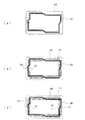
図1(a)に示すように、アンテナコイル11は、絶縁基板14上に積層された銅箔をエッチングすることにより作製したものであり、そのアンテナコイルの端部12、13にはICチップが電気的に接続されている(ただし、省略している。)。アンテナコイル11の形状は、図1(b)に示すように、2枚のICカードを向かい合わせて重ねたときに、互いのアンテナコイルの重なる面積が少なくなるように迂回して形成されている。また、2枚のICカードを向かい合わせて重ねた場合、重ね方には2種類あり、もう一方は、図1(c)に示すように、上のカードのアンテナコイルの端部12,13はカードの左側に、下のカードのアンテナコイルの端部12,13はカードの右側に位置しているように重ねるものであり、どちらの場合でも、アンテナコイル11の重なる面積が少なくなるように形成されている。
As shown in FIG. 1 (a), the
また、図2(a)に示すようなアンテナコイルが、プラスチックフィルムの両面に形成され、その形状が、図2(b)に示すように、2枚のICカードを重ねたときに、向かい合ったプリントコイルの重なる面積が少なくなるような形状とすることができる。この場合も、重ね方に2とおりあるが、その2とおりのどちらでも、向かい合ったプリントコイルの重なる面積が少なくなるような形状とすることが好ましい。 In addition, antenna coils as shown in FIG. 2 (a) are formed on both surfaces of a plastic film, and the shapes thereof face each other when two IC cards are stacked as shown in FIG. 2 (b). It can be made into the shape where the area which a printed coil overlaps decreases. In this case as well, there are two ways of overlapping, but it is preferable to use a shape that reduces the overlapping area of the printed coils facing each other.
上に述べた実施例は、絶縁基板上に積層された銅箔をエッチングすることにより作製したアンテナコイルついて説明したが、本発明はこれに限るものではなく、被覆された電線(例えば、エナメル線)を同一面上に巻き回したもの、絶縁基板上に接着されたアルミ箔をエッチングすることにより作製したもの、また絶縁基板上にいわゆる導電性ペーストを印刷して、アンテナコイルを形成したもの等にも適用することができる。 In the above-described embodiment, the antenna coil manufactured by etching the copper foil laminated on the insulating substrate has been described. However, the present invention is not limited to this, and the coated electric wire (for example, enameled wire) is described. ) Wound on the same surface, manufactured by etching an aluminum foil adhered on an insulating substrate, or what is called a conductive paste printed on an insulating substrate to form an antenna coil, etc. It can also be applied to.
1,11.アンテナコイル
2.ICチップ
3.被覆部材
4,5,12,13.アンテナコイルの端部
6,7.ICチップのバンプ
8.カード
9.カードの裏面
10.カードの表面
14.絶縁基板
1,11. 1. Antenna coil IC chip3.
Claims (3)
上記アンテナコイルが、2枚のICカードを向かい合わせて重ねたときに、互いのアンテナコイルの重なる面積が少なくなるように形成されているICカード。 In an IC card configured to include an antenna coil, an IC chip, an insulating substrate, and a covering member, and electrically connecting the IC chip to the terminal of the antenna coil,
An IC card in which the antenna coil is formed so that the area where the antenna coils overlap is reduced when two IC cards are stacked facing each other.
Priority Applications (1)
| Application Number | Priority Date | Filing Date | Title |
|---|---|---|---|
| JP2010196068A JP2010277609A (en) | 2010-09-01 | 2010-09-01 | Ic card |
Applications Claiming Priority (1)
| Application Number | Priority Date | Filing Date | Title |
|---|---|---|---|
| JP2010196068A JP2010277609A (en) | 2010-09-01 | 2010-09-01 | Ic card |
Related Parent Applications (1)
| Application Number | Title | Priority Date | Filing Date |
|---|---|---|---|
| JP2007320091A Division JP2008090863A (en) | 2007-12-11 | 2007-12-11 | Ic card |
Publications (1)
| Publication Number | Publication Date |
|---|---|
| JP2010277609A true JP2010277609A (en) | 2010-12-09 |
Family
ID=43424451
Family Applications (1)
| Application Number | Title | Priority Date | Filing Date |
|---|---|---|---|
| JP2010196068A Pending JP2010277609A (en) | 2010-09-01 | 2010-09-01 | Ic card |
Country Status (1)
| Country | Link |
|---|---|
| JP (1) | JP2010277609A (en) |
Citations (12)
| Publication number | Priority date | Publication date | Assignee | Title |
|---|---|---|---|---|
| JPS61283981A (en) * | 1985-06-11 | 1986-12-13 | Nippon Denzai Kogyo Kenkyusho:Kk | Integrated circuit card |
| JPH04292998A (en) * | 1991-03-20 | 1992-10-16 | Toshiba Corp | Ic card |
| JPH05128324A (en) * | 1991-11-07 | 1993-05-25 | Mitsubishi Electric Corp | Non-contact card, terminal machine for non-contact card, and non-contact transmission system |
| JPH0785325A (en) * | 1993-09-10 | 1995-03-31 | Toshiba Corp | Gate system |
| JPH08180160A (en) * | 1994-12-22 | 1996-07-12 | Sony Corp | Ic card |
| JPH08216570A (en) * | 1995-02-09 | 1996-08-27 | Hitachi Chem Co Ltd | Ic card |
| JPH08287208A (en) * | 1995-04-13 | 1996-11-01 | Sony Chem Corp | Noncontact ic card and its manufacture |
| JPH09181520A (en) * | 1995-12-22 | 1997-07-11 | Mitsubishi Electric Corp | Thin receiver and transmitter |
| JPH1090404A (en) * | 1996-09-20 | 1998-04-10 | Toshiba Corp | Radio card |
| JPH10126318A (en) * | 1996-10-11 | 1998-05-15 | Omron Corp | Noncontact medium and noncontact transmission system |
| JPH10193851A (en) * | 1997-01-08 | 1998-07-28 | Denso Corp | Non-contact card |
| JPH10203066A (en) * | 1997-01-28 | 1998-08-04 | Hitachi Ltd | Non-contact ic card |
-
2010
- 2010-09-01 JP JP2010196068A patent/JP2010277609A/en active Pending
Patent Citations (12)
| Publication number | Priority date | Publication date | Assignee | Title |
|---|---|---|---|---|
| JPS61283981A (en) * | 1985-06-11 | 1986-12-13 | Nippon Denzai Kogyo Kenkyusho:Kk | Integrated circuit card |
| JPH04292998A (en) * | 1991-03-20 | 1992-10-16 | Toshiba Corp | Ic card |
| JPH05128324A (en) * | 1991-11-07 | 1993-05-25 | Mitsubishi Electric Corp | Non-contact card, terminal machine for non-contact card, and non-contact transmission system |
| JPH0785325A (en) * | 1993-09-10 | 1995-03-31 | Toshiba Corp | Gate system |
| JPH08180160A (en) * | 1994-12-22 | 1996-07-12 | Sony Corp | Ic card |
| JPH08216570A (en) * | 1995-02-09 | 1996-08-27 | Hitachi Chem Co Ltd | Ic card |
| JPH08287208A (en) * | 1995-04-13 | 1996-11-01 | Sony Chem Corp | Noncontact ic card and its manufacture |
| JPH09181520A (en) * | 1995-12-22 | 1997-07-11 | Mitsubishi Electric Corp | Thin receiver and transmitter |
| JPH1090404A (en) * | 1996-09-20 | 1998-04-10 | Toshiba Corp | Radio card |
| JPH10126318A (en) * | 1996-10-11 | 1998-05-15 | Omron Corp | Noncontact medium and noncontact transmission system |
| JPH10193851A (en) * | 1997-01-08 | 1998-07-28 | Denso Corp | Non-contact card |
| JPH10203066A (en) * | 1997-01-28 | 1998-08-04 | Hitachi Ltd | Non-contact ic card |
Similar Documents
| Publication | Publication Date | Title |
|---|---|---|
| JP5260031B2 (en) | Wireless transmission / reception device, non-contact information recording medium, information reading / writing device, and management system | |
| JP2010268306A (en) | Coil antenna | |
| US20100321267A1 (en) | Antenna device | |
| JP2008140398A (en) | Ic card | |
| JP4106764B2 (en) | IC card | |
| JP5637004B2 (en) | Semiconductor integrated circuit module, wireless communication module, and wireless communication device | |
| JP6172418B2 (en) | ANTENNA DEVICE, CARD TYPE INFORMATION MEDIUM, ELECTRONIC DEVICE, AND ANTENNA DEVICE MANUFACTURING METHOD | |
| JP2009064454A (en) | Non-contact ic card | |
| JP2008090863A (en) | Ic card | |
| JP4556002B2 (en) | Non-contact IC card | |
| JP4238924B2 (en) | Non-contact IC card | |
| JP4314591B2 (en) | IC card | |
| JP4314592B2 (en) | IC card | |
| JP2007281315A (en) | Coil component | |
| JP2008125104A (en) | Antenna film for ic card | |
| JP2008102957A (en) | Non-contact ic card | |
| JP2010277609A (en) | Ic card | |
| JP2001143029A (en) | Manufacturing method of ic card | |
| JP2008108273A (en) | Ic card | |
| JP2008077691A (en) | Ic card | |
| JP2008077689A (en) | Ic card | |
| JP2008077692A (en) | Method for reading ic card | |
| JP2008077690A (en) | Ic card | |
| JP2001005930A (en) | Ic card | |
| JP5603396B2 (en) | Wireless transceiver, non-contact information recording medium, management system, and transmission / reception system |
Legal Events
| Date | Code | Title | Description |
|---|---|---|---|
| A621 | Written request for application examination |
Free format text: JAPANESE INTERMEDIATE CODE: A621 Effective date: 20100901 |
|
| A521 | Written amendment |
Free format text: JAPANESE INTERMEDIATE CODE: A523 Effective date: 20110816 |
|
| A131 | Notification of reasons for refusal |
Free format text: JAPANESE INTERMEDIATE CODE: A131 Effective date: 20110920 |
|
| A02 | Decision of refusal |
Free format text: JAPANESE INTERMEDIATE CODE: A02 Effective date: 20120131 |