JP2010263296A - Elastic boundary wave device - Google Patents
Elastic boundary wave device Download PDFInfo
- Publication number
- JP2010263296A JP2010263296A JP2009110756A JP2009110756A JP2010263296A JP 2010263296 A JP2010263296 A JP 2010263296A JP 2009110756 A JP2009110756 A JP 2009110756A JP 2009110756 A JP2009110756 A JP 2009110756A JP 2010263296 A JP2010263296 A JP 2010263296A
- Authority
- JP
- Japan
- Prior art keywords
- acoustic wave
- boundary acoustic
- filter unit
- resonator
- boundary
- Prior art date
- Legal status (The legal status is an assumption and is not a legal conclusion. Google has not performed a legal analysis and makes no representation as to the accuracy of the status listed.)
- Withdrawn
Links
Images


Abstract
Description
本発明は、弾性境界波装置に関し、詳細には、縦結合共振子型弾性境界波フィルタ部と、フィルタ部に接続されている弾性境界波共振子とを有する弾性境界波装置に関する。 The present invention relates to a boundary acoustic wave device, and more particularly, to a boundary acoustic wave device including a longitudinally coupled resonator type boundary acoustic wave filter unit and a boundary acoustic wave resonator connected to the filter unit.
近年、複数種類のバンドの送受信が可能な通信端末などに、帯域阻止フィルタなどの弾性波装置が多用されるようになってきている。弾性波装置には、現在最も広く用いられている弾性表面波装置の他に、例えば下記の特許文献1などに開示されている弾性境界波装置が知られている。弾性境界波装置は、弾性表面波装置と比べて小型化が可能であるため、大きな注目を集めている。
In recent years, an elastic wave device such as a band rejection filter has been widely used in communication terminals capable of transmitting and receiving a plurality of types of bands. As the acoustic wave device, in addition to the most widely used surface acoustic wave device, a boundary acoustic wave device disclosed in, for example, the following
弾性境界波装置は、圧電基板と、圧電基板の上に形成されている第1の誘電体層と、第1の誘電体層の上に形成されている第2の誘電体層と、圧電基板と第1の誘電体層との境界に形成されているIDT電極とを備えている。第2の誘電体層は、第1の誘電体層よりも音速が速い誘電体層である。典型的には、第1の誘電体層が酸化ケイ素で形成され、第2の誘電体層が窒化珪素で形成される。 The boundary acoustic wave device includes a piezoelectric substrate, a first dielectric layer formed on the piezoelectric substrate, a second dielectric layer formed on the first dielectric layer, and a piezoelectric substrate. And an IDT electrode formed at a boundary between the first dielectric layer and the first dielectric layer. The second dielectric layer is a dielectric layer having a higher speed of sound than the first dielectric layer. Typically, the first dielectric layer is formed from silicon oxide and the second dielectric layer is formed from silicon nitride.
上述のように、弾性境界波装置は、弾性表面波装置と比べて小型化が可能である。しかしながら、フィルタ機能を有する弾性境界波装置では、フィルタ部を構成するIDT電極において発生した弾性境界波の高次モードが第1の誘電体層に閉じ込められ、これに起因してスプリアスが発生するという問題があった。 As described above, the boundary acoustic wave device can be downsized as compared with the surface acoustic wave device. However, in the boundary acoustic wave device having a filter function, higher-order modes of the boundary acoustic waves generated in the IDT electrodes constituting the filter unit are confined in the first dielectric layer, which causes spurious. There was a problem.
本発明は、かかる点に鑑みてなされたものであり、その目的は、フィルタ部を有する弾性境界波装置において、高次モードに起因するスプリアスを抑圧することにある。 The present invention has been made in view of such a point, and an object thereof is to suppress spurious due to a higher-order mode in a boundary acoustic wave device having a filter section.
本発明に係る弾性境界波装置は、弾性境界波フィルタ部と、弾性境界波共振子とを備えている。弾性境界波フィルタ部は、入力端子と出力端子とを有する。弾性境界波共振子は、弾性境界波フィルタ部に接続されている。本発明に係る弾性境界波装置においては、弾性境界波共振子において発生する弾性境界波の高次モードの応答の周波数と、弾性境界波フィルタ部において発生する弾性境界波の高次モードの応答の周波数とが等しくされている。 The boundary acoustic wave device according to the present invention includes a boundary acoustic wave filter unit and a boundary acoustic wave resonator. The boundary acoustic wave filter unit has an input terminal and an output terminal. The boundary acoustic wave resonator is connected to the boundary acoustic wave filter unit. In the boundary acoustic wave device according to the present invention, the frequency of the higher-order mode response of the boundary acoustic wave generated in the boundary acoustic wave resonator and the response of the higher-order mode of the boundary acoustic wave generated in the boundary acoustic wave filter unit. The frequency is made equal.
本発明に係る弾性境界波装置のある特定の局面では、弾性境界波共振子は、入力端子または出力端子と、弾性境界波フィルタ部との間に接続されている。 In a specific aspect of the boundary acoustic wave device according to the present invention, the boundary acoustic wave resonator is connected between the input terminal or the output terminal and the boundary acoustic wave filter unit.
本発明に係る弾性境界波装置の他の特定の局面では、弾性境界波共振子は、入力端子と、弾性境界波フィルタ部との間に接続されている。 In another specific aspect of the boundary acoustic wave device according to the present invention, the boundary acoustic wave resonator is connected between the input terminal and the boundary acoustic wave filter unit.
本発明に係る弾性境界波装置の別の特定の局面では、弾性境界波フィルタ部は、縦結合共振子型弾性境界波フィルタ部である。 In another specific aspect of the boundary acoustic wave device according to the present invention, the boundary acoustic wave filter unit is a longitudinally coupled resonator type boundary acoustic wave filter unit.
本発明に係る弾性境界波装置のさらに他の特定の局面では、弾性境界波共振子において発生する弾性境界波のメインモードの応答の周波数と、弾性境界波フィルタ部において発生する弾性境界波のメインモードの応答の周波数とが相互に異なる。この構成によれば、弾性境界波共振子において発生する弾性境界波のメインモードによってフィルタ特性が悪化することを抑制することができる。具体的には、弾性境界波共振子において発生する弾性境界波のメインモードに起因するスプリアスが発生することを抑制することができる。 In still another specific aspect of the boundary acoustic wave device according to the present invention, the frequency of the response of the main mode of the boundary acoustic wave generated in the boundary acoustic wave resonator and the main boundary acoustic wave generated in the boundary acoustic wave filter unit. The frequency of the mode response is different from each other. According to this structure, it can suppress that a filter characteristic deteriorates by the main mode of the boundary acoustic wave which generate | occur | produces in a boundary acoustic wave resonator. Specifically, it is possible to suppress the occurrence of spurious due to the main mode of the boundary acoustic wave generated in the boundary acoustic wave resonator.
本発明に係る弾性境界波装置のさらに別の特定の局面では、弾性境界波フィルタ部と弾性境界波共振子とのそれぞれは、圧電基板と、圧電基板の上に形成されている第1の誘電体層と、第1の誘電体層の上に形成されており、第1の誘電体層よりも音速が高い第2の誘電体層と、圧電基板と第1の誘電体層との境界に形成されているIDT電極とを有し、弾性境界波共振子において発生する弾性境界波のメインモードの応答の周波数と、弾性境界波フィルタ部において発生する弾性境界波のメインモードの応答の周波数とが相互に異なるように、弾性境界波共振子と弾性境界波フィルタ部との間で、IDT電極の波長、IDT電極のデューティー及び第1の誘電体層の厚みのうちの少なくともひとつが異ならさられている。 In still another specific aspect of the boundary acoustic wave device according to the present invention, each of the boundary acoustic wave filter unit and the boundary acoustic wave resonator includes a piezoelectric substrate and a first dielectric formed on the piezoelectric substrate. A body layer, a second dielectric layer formed on the first dielectric layer and having a higher sound velocity than the first dielectric layer, and a boundary between the piezoelectric substrate and the first dielectric layer. And the frequency of the main mode response of the boundary acoustic wave generated in the boundary acoustic wave resonator, and the frequency of the response of the main mode of the boundary acoustic wave generated in the boundary acoustic wave filter unit. Are different from each other in at least one of the wavelength of the IDT electrode, the duty of the IDT electrode, and the thickness of the first dielectric layer between the boundary acoustic wave resonator and the boundary acoustic wave filter unit. ing.
本発明に係る弾性境界波装置のまた他の特定の局面では、第1の誘電体層が酸化ケイ素からなり、第2の誘電体層が窒化珪素からなる。 In another specific aspect of the boundary acoustic wave device according to the present invention, the first dielectric layer is made of silicon oxide, and the second dielectric layer is made of silicon nitride.
本発明では、弾性境界波共振子において発生する弾性境界波の高次モードの応答の周波数と、弾性境界波フィルタ部において発生する弾性境界波の高次モードの応答の周波数とが等しくされているため、弾性境界波共振子において発生する弾性境界波の高次モードにより、弾性境界波フィルタ部において発生する弾性境界波の高次モードに起因するスプリアスを抑圧することができる。 In the present invention, the frequency of the higher-order mode response of the boundary acoustic wave generated in the boundary acoustic wave resonator is made equal to the frequency of the higher-order mode response of the boundary acoustic wave generated in the boundary acoustic wave filter unit. Therefore, the spurious attributed to the higher order mode of the boundary acoustic wave generated in the boundary acoustic wave filter unit can be suppressed by the higher order mode of the boundary acoustic wave generated in the boundary acoustic wave resonator.
以下、図面を参照しつつ、本発明の具体的な実施形態を説明することにより、本発明を明らかにする。 Hereinafter, the present invention will be clarified by describing specific embodiments of the present invention with reference to the drawings.
図1は、本実施形態に係る弾性境界波装置の略図的模式図である。図2は、本実施形態に係る弾性境界波装置のIDT電極が形成されている部分を拡大した略図的断面図である。なお、図1では、描画の便宜上、IDT電極及び反射器における電極指の本数等は実際の本数よりも少なく描画している。 FIG. 1 is a schematic diagram of a boundary acoustic wave device according to this embodiment. FIG. 2 is a schematic cross-sectional view in which a portion where the IDT electrode of the boundary acoustic wave device according to the present embodiment is formed is enlarged. In FIG. 1, for convenience of drawing, the number of electrode fingers and the like in the IDT electrode and the reflector are drawn less than the actual number.
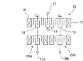
本実施形態の弾性境界波装置1は、SH型弾性境界波を利用した弾性境界波装置である。図1に示すように、本実施形態の弾性境界波装置1は、縦結合共振子型弾性境界波フィルタ部10を備えている。縦結合共振子型弾性境界波フィルタ部10は、入力端子(平衡信号端子)11と、第1及び第2の出力端子(平衡信号端子)12a、12bとを備える平衡−不平衡変換機能を備えるバランス型の縦結合共振子型弾性境界波フィルタ部である。
The boundary
縦結合共振子型弾性境界波フィルタ部10は、所謂3IDT型の縦結合共振子型弾性波フィルタ部である。縦結合共振子型弾性境界波フィルタ部10は、弾性境界波伝搬方向に沿って配列されている第1〜第3のIDT電極13〜15と、第1〜第3のIDT電極13〜15が設けられた領域の弾性境界波伝搬方向の両側に配置された第1及び第2のグレーティング反射器16,17とを備えている。第1〜第3のIDT電極13〜15のうちの中央に位置する第2のIDT電極14の一端側が入力端子11に接続されている。一方、第2のIDT電極14の他端側がグラウンド電極に接続されている。第2のIDT電極14の弾性境界波伝搬方向の両側に位置する第1及び第3のIDT電極13,15のそれぞれの一端側は、グラウンド電極に接続されている。第1のIDT電極13の他端側は、第1の出力端子12aに接続されている。一方、第3のIDT電極15の他端側は、第2の出力端子12bに接続されている。
The longitudinally coupled resonator type boundary acoustic
縦結合共振子型弾性境界波フィルタ部10と、入力端子11との間には、弾性境界波共振子20が接続されている。すなわち、縦結合共振子型弾性境界波フィルタ部10と、弾性境界波共振子20とは、直列に接続されている。
A boundary
弾性境界波共振子20は、IDT電極21と、IDT電極21の弾性境界波伝搬方向の両側に配置されている第1及び第2のグレーティング反射器22,23とを備えている。IDT電極21の一方側が入力端子11に接続されている。IDT電極21の他方側が縦結合共振子型弾性境界波フィルタ部10の第2のIDT電極14の一方側に接続されている。
The boundary
次に、縦結合共振子型弾性境界波フィルタ部10及び弾性境界波共振子20の膜構成について、図2を参照しつつ詳細に説明する。縦結合共振子型弾性境界波フィルタ部10及び弾性境界波共振子20のそれぞれは、圧電基板30を備えている。本実施形態では、圧電基板30が、27.5° Y−X LiNbO3基板により形成されている。最も、圧電基板30は、これに限定されず、例えば、LiNbO3やLiTaO3、水晶などの適宜の圧電材料により形成することができる。
Next, the film configuration of the longitudinally coupled resonator type boundary acoustic
圧電基板30の上には、第1の誘電体層31が形成されている。第1の誘電体層31の上には、第2の誘電体層32が形成されている。本実施形態では、第1の誘電体層31が酸化ケイ素により形成されており、第2の誘電体層32が窒化珪素により形成されている。もっとも、第1及び第2の誘電体層31,32の形成材料は、第2の誘電体層32の音速が、第1の誘電体層31の音速よりも高くなる限りにおいて、特に限定されず、上記条件が満たされる範囲内で適宜選択することができる。
A
本実施形態では、圧電基板30と第1の誘電体層31との境界に、例えば、Ta2O5などからなる下地層33が形成されている。そして、下地層33の上に、上述のIDT電極13〜15,21及びグレーティング反射器16,17,22,23が形成されている。もっとも、本発明において、下地層は必須の構成ではない。下地層を設けず、圧電基板と第1の誘電体層との境界にIDT電極や反射器等を形成してもよい。なお、図2及び以下の説明では、説明の便宜上、IDT電極13〜15,21を、IDT電極40と総称している。
In the present embodiment, a
IDT電極40は、Al,Ag、Au、Pt、Cu、Tiなどの金属や、AlCuなどのこれらの金属を主成分として含む合金等の適宜の導電材料に形成することができる。IDT電極40は、1層の導電層により構成されていてもよいし、複数層の導電層の積層体により構成されていてもよい。さらに、IDT電極40には、下地層33や第1の誘電体層31との密着性を向上するための密着層が設けられていてもよい。本実施形態では、具体的には、IDT電極40は、下地層33の上に、Ti層41,Pt層(第1の主電極層)42、Ti層43、AlCu層(第1の導電層)44、Ti層45、Pt層(第2の主電極層)46、Ti層47、AlCu層(第2の導電層)48、Ti層49が、圧電基板30側からこの順番に形成された積層体により構成されている。
The
本実施形態では、弾性境界波共振子20において発生する弾性境界波の高次モードの応答の周波数と、縦結合共振子型弾性境界波フィルタ部10において発生する弾性境界波の高次モードの応答の周波数とが等しくされている。具体的には、本実施形態では、弾性境界波共振子20において発生する弾性境界波の高次モードの反共振周波数と、縦結合共振子型弾性境界波フィルタ部10において発生する弾性境界波の高次モードの応答の周波数とが等しくされている。このため、弾性境界波共振子20において発生する弾性境界波の高次モードにより、縦結合共振子型弾性境界波フィルタ部10において発生する弾性境界波の高次モードに起因するスプリアスを抑圧することができる。
In the present embodiment, the frequency of the higher order mode response of the boundary acoustic wave generated in the boundary
なお、本明細書において、「弾性境界波フィルタ部において発生する弾性境界波の高次モードの応答の周波数」とは、弾性境界波フィルタ部において発生する弾性境界波の高次モードにより形成される通過帯域または阻止帯域の周波数帯のことをいう。 In this specification, “the frequency of the response of the higher order mode of the boundary acoustic wave generated in the boundary acoustic wave filter unit” is formed by the higher order mode of the boundary acoustic wave generated in the boundary acoustic wave filter unit. The frequency band of the pass band or stop band.
また、高次モードには、2次モードのみならず、3次以上のモードが含まれる。すなわち、「弾性境界波共振子において発生する弾性境界波の高次モードの応答の周波数と、弾性境界波フィルタ部において発生する弾性境界波の高次モードの応答の周波数とが等しい」とは、弾性境界波共振子において発生する弾性境界波の2次以上の高次モードのいずれかの応答の周波数と、弾性境界波フィルタ部において発生する弾性境界波の2次以上の高次モードのいずれかの応答により形成される通過帯域または阻止帯域の周波数帯とが等しいことを意味する。 The higher-order mode includes not only the secondary mode but also the third and higher modes. That is, “the frequency of the higher-order mode response of the boundary acoustic wave generated in the boundary acoustic wave resonator is equal to the frequency of the higher-order mode response of the boundary acoustic wave generated in the boundary acoustic wave filter unit” The frequency of any one of the second and higher order modes of the boundary acoustic wave generated in the boundary acoustic wave resonator and any one of the second and higher order modes of the boundary acoustic wave generated in the boundary acoustic wave filter unit This means that the passband or stopband frequency band formed by the response is equal.
例えば、弾性境界波共振子において発生する弾性境界波の3次モードの応答の周波数と、弾性境界波フィルタ部において発生する弾性境界波の2次モードの応答により形成される通過帯域または阻止帯域の周波数帯とが等しくてもよい。但し、より高いモードになるほど応答が小さくなるため、弾性境界波共振子において発生する弾性境界波の2次モードの応答の周波数と、弾性境界波フィルタ部において発生する弾性境界波の2次モードの応答により形成される通過帯域または阻止帯域の周波数帯とが等しくされていることが好ましい。そうすることにより、高次モードスプリアスをより効果的に抑圧することができる。 For example, the passband or stopband formed by the frequency of the response of the third order mode of the boundary acoustic wave generated in the boundary acoustic wave resonator and the response of the second order mode of the boundary acoustic wave generated in the boundary acoustic wave filter unit. The frequency band may be equal. However, since the response becomes smaller as the mode becomes higher, the frequency of the response of the secondary mode of the boundary acoustic wave generated in the boundary acoustic wave resonator and the secondary mode of the boundary acoustic wave generated in the boundary acoustic wave filter unit. The frequency band of the pass band or stop band formed by the response is preferably made equal. By doing so, higher-order mode spurious can be suppressed more effectively.
また、弾性境界波共振子において発生する弾性境界波の高次モードの応答の周波数とは、本実施形態のように弾性境界波共振子が弾性境界波フィルタ部と直列に接続されている場合は、弾性境界波共振子において発生する弾性境界波の高次モードの反共振周波数となる。弾性境界波共振子が入力端子または出力端子と弾性境界波フィルタ部との間の接続点と、グラウンド電位との間に接続されている場合は、弾性境界波共振子において発生する弾性境界波の高次モードの共振周波数となる。 The frequency of the response of the higher order mode of the boundary acoustic wave generated in the boundary acoustic wave resonator is the case where the boundary acoustic wave resonator is connected in series with the boundary acoustic wave filter unit as in this embodiment. This is the antiresonance frequency of the higher order mode of the boundary acoustic wave generated in the boundary acoustic wave resonator. When the boundary acoustic wave resonator is connected between the connection point between the input terminal or the output terminal and the boundary acoustic wave filter unit and the ground potential, the boundary acoustic wave generated in the boundary acoustic wave resonator is The resonance frequency of the higher order mode.
以下、この効果を具体例に基づいてさらに詳細に説明する。 Hereinafter, this effect will be described in more detail based on specific examples.
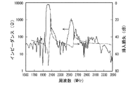
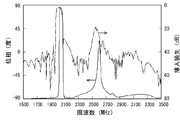
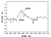
図3は、弾性境界波共振子において発生する弾性境界波の高次モードの応答の周波数と、弾性境界波フィルタ部において発生する弾性境界波の高次モードの応答の周波数とが等しくされていない比較例としての弾性境界波装置の伝送特性を表すグラフである。また、図4は、比較例における弾性境界波共振子のインピーダンス特性を表すグラフであり、図5は、比較例における弾性境界波共振子のインピーダンス特性と、弾性境界波装置の挿入損失を併記したグラフである。図6は、比較例における弾性境界波共振子の位相特性を表すグラフである。図7は、比較例における弾性境界波共振子の位相特性及び弾性境界波装置の挿入損失を併記したグラフである。 FIG. 3 shows that the frequency of the high-order mode response of the boundary acoustic wave generated in the boundary acoustic wave resonator is not equal to the frequency of the high-order mode response of the boundary acoustic wave generated in the boundary acoustic wave filter unit. It is a graph showing the transmission characteristic of the boundary acoustic wave apparatus as a comparative example. FIG. 4 is a graph showing the impedance characteristics of the boundary acoustic wave resonator in the comparative example, and FIG. 5 shows both the impedance characteristics of the boundary acoustic wave resonator in the comparative example and the insertion loss of the boundary acoustic wave device. It is a graph. FIG. 6 is a graph showing the phase characteristics of the boundary acoustic wave resonator in the comparative example. FIG. 7 is a graph showing both the phase characteristics of the boundary acoustic wave resonator and the insertion loss of the boundary acoustic wave device in the comparative example.
図3に示す例では、弾性境界波フィルタ部において発生する弾性境界波の高次モードに起因するスプリアスが2500MHz付近に発生している。スプリアスが生じている部分の挿入損失は、17dB程度となっている。そして、図5に示すグラフから、弾性境界波共振子の高次モードは、スプリアスの周波数である2500MHzとは異なる2600MHz付近に現れていることがわかる。このことから、比較例においては、弾性境界波共振子において発生する弾性境界波の高次モードの応答の周波数と、弾性境界波フィルタ部において発生する弾性境界波の高次モードの応答の周波数とが等しくないことが分かる。 In the example shown in FIG. 3, spurious due to the higher order mode of the boundary acoustic wave generated in the boundary acoustic wave filter unit is generated in the vicinity of 2500 MHz. The insertion loss of the spurious portion is about 17 dB. From the graph shown in FIG. 5, it can be seen that the higher order mode of the boundary acoustic wave resonator appears in the vicinity of 2600 MHz, which is different from the spurious frequency of 2500 MHz. Therefore, in the comparative example, the frequency of the response of the higher order mode of the boundary acoustic wave generated in the boundary acoustic wave resonator and the frequency of the response of the higher order mode of the boundary acoustic wave generated in the boundary acoustic wave filter unit are It can be seen that are not equal.
それに対して、本実施形態では、図9及び図10に示すように、弾性境界波共振子20において発生する弾性境界波の高次モードの応答の周波数と、縦結合共振子型弾性境界波フィルタ部10において発生する弾性境界波の高次モードの応答の周波数とが等しくされている。具体的には、本実施形態では、弾性境界波共振子20において発生する弾性境界波の高次モードの反共振周波数と、縦結合共振子型弾性境界波フィルタ部10において発生する弾性境界波の高次モードの応答の周波数、すなわち、通過帯域の周波数帯とが等しくされている。このため、図8〜図10に示すように、弾性境界波共振子20において発生する弾性境界波の高次モードにより、縦結合共振子型弾性境界波フィルタ部10において発生する弾性境界波の薄膜高次モードに起因するスプリアスを抑圧することができる。具体的には、本実施例及び比較例においては、5dB程度スプリアスが抑圧されている。
On the other hand, in this embodiment, as shown in FIGS. 9 and 10, the frequency of the higher-order mode response of the boundary acoustic wave generated in the boundary
以上の結果から、弾性境界波共振子において発生する弾性境界波の高次モードの応答の周波数と、弾性境界波フィルタ部において発生する弾性境界波の高次モードの応答の周波数とを等しくすることにより、弾性境界波共振子において発生する弾性境界波の高次モードにより、弾性境界波フィルタ部において発生する弾性境界波の高次モードに起因するスプリアスを抑圧できることがわかる。 Based on the above results, the frequency of the higher-order mode response of the boundary acoustic wave generated in the boundary acoustic wave resonator is equal to the frequency of the higher-order mode response of the boundary acoustic wave generated in the boundary acoustic wave filter section. Thus, it is understood that the spurious attributed to the higher order mode of the boundary acoustic wave generated in the boundary acoustic wave filter unit can be suppressed by the higher order mode of the boundary acoustic wave generated in the boundary acoustic wave resonator.
なお、本実施形態において、弾性境界波共振子20において発生する弾性境界波のメインモードの応答の周波数と、縦結合共振子型弾性境界波フィルタ部10において発生する弾性境界波のメインモードの応答の周波数とが相互に異ならしめられていることが好ましい。このようにすることによって、弾性境界波共振子20において発生する弾性境界波のメインモードによってフィルタ特性が悪化することを抑制することができる。弾性境界波共振子20において発生する弾性境界波のメインモードに起因するスプリアスが発生することを抑制することができる。
In this embodiment, the frequency of the main mode response of the boundary acoustic wave generated in the boundary
なお、本明細書において、「弾性境界波フィルタ部のメインモードの応答の周波数」とは、弾性境界波フィルタ部において発生する弾性境界波のメインモードにより形成される通過帯域または阻止帯域の周波数帯のことをいう。 In the present specification, the “frequency of the main mode response of the boundary acoustic wave filter unit” refers to the frequency band of the pass band or stop band formed by the main mode of the boundary acoustic wave generated in the boundary acoustic wave filter unit. I mean.
また、「弾性境界波共振子において発生する弾性境界波のメインモードの応答の周波数」とは、本実施形態のように、弾性境界波共振子が弾性境界波フィルタ部と直列に接続されている場合は、弾性境界波共振子において発生する弾性境界波のメインモードの反共振周波数となる。弾性境界波共振子が入力端子または出力端子と弾性境界波フィルタ部との間の接続点と、グラウンド電位との間に接続されている場合は、弾性境界波共振子において発生する弾性境界波の高次モードの共振周波数となる。 The “frequency of the main mode response of the boundary acoustic wave generated in the boundary acoustic wave resonator” means that the boundary acoustic wave resonator is connected in series with the boundary acoustic wave filter unit as in this embodiment. In this case, the antiresonance frequency of the main mode of the boundary acoustic wave generated in the boundary acoustic wave resonator is obtained. When the boundary acoustic wave resonator is connected between the connection point between the input terminal or the output terminal and the boundary acoustic wave filter unit and the ground potential, the boundary acoustic wave generated in the boundary acoustic wave resonator is The resonance frequency of the higher order mode.
弾性境界波共振子20と縦結合共振子型弾性境界波フィルタ部10とにおいて、高次モードの応答の周波数を相互に同じにすると共に、メインモードの応答の周波数を相互に異ならせる方法は、特に限定されない。メインモードの応答の周波数を相互に異ならせる方法としては、例えば、IDT電極の波長(λ)、デューティー及び第1の誘電体層31の厚みのうちのひとつを弾性境界波共振子20と縦結合共振子型弾性境界波フィルタ部10とで異ならしめる方法が挙げられる。
In the boundary
なお、上記実施例及び比較例における設計パラメータは、下記の通りである。 The design parameters in the above examples and comparative examples are as follows.
実施例:
圧電基板30:27.5° Y−X LiNbO3基板
IDT電極40:Ti層41(10nm)、Pt層42(23nm)、Ti層43(10nm)、AlCu層44(175nm)、Ti層45(10nm)、Pt層46(23nm)、Ti層47(10nm)、AlCu層48(100nm)、Ti層49(10nm)
第1の誘電体層31:厚さ550nmの酸化ケイ素層
第2の誘電体層32:厚さ2000nmの窒化珪素層
Example:
Piezoelectric substrate 30: 27.5 ° YX LiNbO 3 substrate IDT electrode 40: Ti layer 41 (10 nm), Pt layer 42 (23 nm), Ti layer 43 (10 nm), AlCu layer 44 (175 nm), Ti layer 45 ( 10 nm), Pt layer 46 (23 nm), Ti layer 47 (10 nm), AlCu layer 48 (100 nm), Ti layer 49 (10 nm)
First dielectric layer 31: silicon oxide layer having a thickness of 550 nm Second dielectric layer 32: silicon nitride layer having a thickness of 2000 nm
縦結合共振子型弾性境界波フィルタ10:
伝搬方向:ψ=0度
交差幅:27λ
デューティー:0.50
反射器16の対数:14.5対
反射器16の波長:1.918μm
IDT13の対数:19.0対
IDT13の波長:1.897μm(但し、IDT14と隣接する8本は波長1.815μm)
IDT14の対数:19.0対
IDT14の波長:1.879μm(但し、IDT13、15と隣接する7本ずつは、波長1.791μm)
IDT15の対数:19.0対
IDT15の波長:1.879μm(但し、IDT14と隣接する8本は波長1.815μm)
反射器17の対数:14.5対
反射器17の波長:1.918μm
Longitudinal coupled resonator type boundary acoustic wave filter 10:
Propagation direction: ψ = 0 degree Cross width: 27λ
Duty: 0.50
Logarithm of reflector 16: 14.5 pair Wavelength of reflector 16: 1.918 μm
Logarithm of IDT13: 19.0 pair Wavelength of IDT13: 1.897 μm (however, eight adjacent to IDT14 have a wavelength of 1.815 μm)
Logarithm of IDT14: 19.0 pair Wavelength of IDT14: 1.879 μm (however, 7 adjacent to IDTs 13 and 15 have a wavelength of 1.791 μm)
Logarithm of IDT15: 19.0 pairs Wavelength of IDT15: 1.879 μm (However, eight adjacent to IDT14 have a wavelength of 1.815 μm)
Logarithm of reflector 17: 14.5 pair Wavelength of reflector 17: 1.918 μm
弾性境界波共振子21:
伝搬方向:ψ=0度
交差幅:30λ
デューティー:0.50
反射器22,23の対数:25対
反射器22,23の波長:1.900μm
IDT21の対数:60.0対
IDT21の波長:1.900μm
Boundary acoustic wave resonator 21:
Propagation direction: ψ = 0 degrees Cross width: 30λ
Duty: 0.50
Logarithm of
Logarithm of IDT21: 60.0 pair Wavelength of IDT21: 1.900 μm
比較例:
圧電基板:27.5° Y−X LiNbO3基板
IDT電極40:Ti層41(10nm)、Pt層42(23nm)、Ti層43(10nm)、AlCu層44(175nm)、Ti層45(10nm)、Pt層46(23nm)、Ti層47(10nm)、AlCu層48(100nm)、Ti層49(10nm)
第1の誘電体層:厚さ550nmの酸化ケイ素層
第2の誘電体層:厚さ2000nmの窒化珪素層
Comparative example:
Piezoelectric substrate: 27.5 ° YX LiNbO 3 substrate IDT electrode 40: Ti layer 41 (10 nm), Pt layer 42 (23 nm), Ti layer 43 (10 nm), AlCu layer 44 (175 nm), Ti layer 45 (10 nm) ), Pt layer 46 (23 nm), Ti layer 47 (10 nm), AlCu layer 48 (100 nm), Ti layer 49 (10 nm)
First dielectric layer: silicon oxide layer having a thickness of 550 nm Second dielectric layer: silicon nitride layer having a thickness of 2000 nm
縦結合共振子型弾性境界波フィルタ10:
伝搬方向:ψ=0度
交差幅:27λ
デューティー:0.50
反射器16の対数:14.5対
反射器16の波長:1.918μm
IDT13の対数:19.0対
IDT13の波長:1.897μm(但し、IDT14と隣接する8本は波長1.815μm)
IDT14の対数:19.0対
IDT14の波長:1.879μm(但し、IDT13、15と隣接する7本ずつは、波長1.791μm)
IDT15の対数:19.0対
IDT15の波長:1.879μm(但し、IDT14と隣接する8本は波長1.815μm)
反射器17の対数:14.5対
反射器17の波長:1.918μm
Longitudinal coupled resonator type boundary acoustic wave filter 10:
Propagation direction: ψ = 0 degree Cross width: 27λ
Duty: 0.50
Logarithm of reflector 16: 14.5 pair Wavelength of reflector 16: 1.918 μm
Logarithm of IDT13: 19.0 pair Wavelength of IDT13: 1.897 μm (however, eight adjacent to IDT14 have a wavelength of 1.815 μm)
Logarithm of IDT14: 19.0 pair Wavelength of IDT14: 1.879 μm (however, 7 adjacent to IDTs 13 and 15 have a wavelength of 1.791 μm)
Logarithm of IDT15: 19.0 pairs Wavelength of IDT15: 1.879 μm (However, eight adjacent to IDT14 have a wavelength of 1.815 μm)
Logarithm of reflector 17: 14.5 pair Wavelength of reflector 17: 1.918 μm
弾性境界波共振子21:
伝搬方向:ψ=0度
交差幅:30λ
デューティー:0.50
反射器16,17のそれぞれの対数:25対
反射器16,17のそれぞれの波長:1.842μm
IDT21の対数:60.0対
IDT21の波長:1.842μm
Boundary acoustic wave resonator 21:
Propagation direction: ψ = 0 degrees Cross width: 30λ
Duty: 0.50
Logarithm of
Logarithm of IDT21: 60.0 pair Wavelength of IDT21: 1.842 μm
以下、上記実施形態の変形例について説明する。但し、以下の変形例の説明において、上記実施形態と実質的に共通の機能を有する部材を共通の符号で参照し、説明を省略する。 Hereinafter, modifications of the embodiment will be described. However, in the following description of the modified examples, members having substantially the same functions as those of the above-described embodiment are referred to by common reference numerals, and description thereof is omitted.
(変形例)
上記実施形態では、弾性境界波共振子が、入力端子と弾性境界波フィルタ部との間に接続されている例について説明した。但し、本発明はこの構成に限定されない。例えば、図11に示すように、縦結合共振子型弾性境界波フィルタ部10と出力端子12a、12bとの間に弾性境界波共振子20a、20bを設けてもよい。
(Modification)
In the above-described embodiment, the example in which the boundary acoustic wave resonator is connected between the input terminal and the boundary acoustic wave filter unit has been described. However, the present invention is not limited to this configuration. For example, as shown in FIG. 11, boundary
また、上記実施形態では、弾性境界波共振子が弾性境界波フィルタ部に対して直列に接続されている例について説明したが、弾性境界波共振子は、入力端子または出力端子と、弾性境界波フィルタ部との間の接続点と、グラウンド電位との間に接続されていてもよい。この場合は、弾性境界波共振子20a、20bにおいて発生する弾性境界波の高次モードの共振周波数と、縦結合共振子型弾性境界波フィルタ部10において発生する弾性境界波の高次モードの周波数とが等しくされる。
In the above embodiment, the boundary acoustic wave resonator is connected in series to the boundary acoustic wave filter unit. However, the boundary acoustic wave resonator includes an input terminal or an output terminal and a boundary acoustic wave. You may connect between the connection point between filter parts, and ground potential. In this case, the higher-order mode resonance frequency of the boundary acoustic wave generated in the boundary
また、上記実施形態では、弾性境界波フィルタ部として、所謂3IDT型の縦結合共振子型弾性波フィルタ部が設けられている例について説明した。但し、本発明において、弾性境界波フィルタ部は、3IDT型の縦結合共振子型弾性波フィルタ部に限定されない。弾性境界波フィルタ部は、例えば、5IDT型または7IDT型の縦結合共振子型弾性波フィルタ部であってもよい。 In the above embodiment, an example in which a so-called 3IDT type longitudinally coupled resonator type acoustic wave filter unit is provided as the boundary acoustic wave filter unit has been described. However, in the present invention, the boundary acoustic wave filter unit is not limited to the 3IDT type longitudinally coupled resonator type acoustic wave filter unit. The boundary acoustic wave filter unit may be, for example, a 5IDT type or 7IDT type longitudinally coupled resonator type elastic wave filter unit.
また、弾性境界波フィルタ部は、例えば、弾性境界波を利用したラダー型フィルタ部などの縦結合共振子型弾性境界波フィルタ部以外の形態のフィルタ部であってもよい。 The boundary acoustic wave filter unit may be a filter unit other than a longitudinally coupled resonator type boundary acoustic wave filter unit such as a ladder type filter unit using boundary acoustic waves.
1…弾性境界波装置
10…縦結合共振子型弾性境界波フィルタ部
11…入力端子
12a…第1の出力端子
12b…第2の出力端子
13…第1のIDT電極
14…第2のIDT電極
15…第3のIDT電極
16…第1のグレーティング反射器
17…第2のグレーティング反射器
20、20a、20b…弾性境界波共振子
21…IDT電極
22…第1のグレーティング反射器
23…第2のグレーティング反射器
30…圧電基板
31…第1の誘電体層
32…第2の誘電体層
33…下地層
40…IDT電極
41、43、45、47、49…Ti層
42…Pt層
44…AlCu層
46…Pt層
48…AlCu層
DESCRIPTION OF
Claims (7)
前記弾性境界波フィルタ部に接続されている弾性境界波共振子とを備え、
前記弾性境界波共振子において発生する弾性境界波の高次モードの応答の周波数と、前記弾性境界波フィルタ部において発生する弾性境界波の高次モードの応答の周波数とが等しい、弾性境界波装置。 A boundary acoustic wave filter unit having an input terminal and an output terminal;
A boundary acoustic wave resonator connected to the boundary acoustic wave filter unit;
A boundary acoustic wave device in which the frequency of the higher order mode response of the boundary acoustic wave generated in the boundary acoustic wave resonator is equal to the frequency of the higher order mode response of the boundary acoustic wave generated in the boundary acoustic wave filter unit. .
前記弾性境界波共振子において発生する弾性境界波のメインモードの応答の周波数と、前記弾性境界波フィルタ部において発生する弾性境界波のメインモードの応答の周波数とが相互に異なるように、前記弾性境界波共振子と前記弾性境界波フィルタ部との間で、前記IDT電極の波長、前記IDT電極のデューティー及び前記第1の誘電体層の厚みのうちの少なくともひとつが異ならされている、請求項5に記載の弾性境界波装置。 Each of the boundary acoustic wave filter unit and the boundary acoustic wave resonator includes a piezoelectric substrate, a first dielectric layer formed on the piezoelectric substrate, and a first dielectric layer. A second dielectric layer formed at a higher speed of sound than the first dielectric layer, and an IDT electrode formed at a boundary between the piezoelectric substrate and the first dielectric layer. ,
The elastic mode is such that the frequency of the response of the main mode of the boundary acoustic wave generated in the boundary acoustic wave resonator is different from the frequency of the response of the main mode of the boundary acoustic wave generated in the boundary acoustic wave filter unit. The at least one of the wavelength of the IDT electrode, the duty of the IDT electrode, and the thickness of the first dielectric layer is different between the boundary wave resonator and the boundary acoustic wave filter unit. 5. The boundary acoustic wave device according to 5.
Priority Applications (1)
| Application Number | Priority Date | Filing Date | Title |
|---|---|---|---|
| JP2009110756A JP2010263296A (en) | 2009-04-30 | 2009-04-30 | Elastic boundary wave device |
Applications Claiming Priority (1)
| Application Number | Priority Date | Filing Date | Title |
|---|---|---|---|
| JP2009110756A JP2010263296A (en) | 2009-04-30 | 2009-04-30 | Elastic boundary wave device |
Publications (1)
| Publication Number | Publication Date |
|---|---|
| JP2010263296A true JP2010263296A (en) | 2010-11-18 |
Family
ID=43361061
Family Applications (1)
| Application Number | Title | Priority Date | Filing Date |
|---|---|---|---|
| JP2009110756A Withdrawn JP2010263296A (en) | 2009-04-30 | 2009-04-30 | Elastic boundary wave device |
Country Status (1)
| Country | Link |
|---|---|
| JP (1) | JP2010263296A (en) |
Cited By (2)
| Publication number | Priority date | Publication date | Assignee | Title |
|---|---|---|---|---|
| JP2019216422A (en) * | 2018-06-13 | 2019-12-19 | スカイワークス ソリューションズ, インコーポレイテッドSkyworks Solutions, Inc. | Frequency control of spurious shear horizontal mode by adding high velocity layer in lithium niobate filter |
| WO2021153734A1 (en) * | 2020-01-31 | 2021-08-05 | 株式会社村田製作所 | Elastic wave device and ladder filter having same |
-
2009
- 2009-04-30 JP JP2009110756A patent/JP2010263296A/en not_active Withdrawn
Cited By (4)
| Publication number | Priority date | Publication date | Assignee | Title |
|---|---|---|---|---|
| JP2019216422A (en) * | 2018-06-13 | 2019-12-19 | スカイワークス ソリューションズ, インコーポレイテッドSkyworks Solutions, Inc. | Frequency control of spurious shear horizontal mode by adding high velocity layer in lithium niobate filter |
| JP7250625B2 (en) | 2018-06-13 | 2023-04-03 | スカイワークス ソリューションズ,インコーポレイテッド | electronic device |
| WO2021153734A1 (en) * | 2020-01-31 | 2021-08-05 | 株式会社村田製作所 | Elastic wave device and ladder filter having same |
| JP7414080B2 (en) | 2020-01-31 | 2024-01-16 | 株式会社村田製作所 | Acoustic wave device and ladder type filter equipped with it |
Similar Documents
| Publication | Publication Date | Title |
|---|---|---|
| JP6555346B2 (en) | Elastic wave filter device | |
| JP6133216B2 (en) | Ladder type elastic wave filter and antenna duplexer using the same | |
| JP5182459B2 (en) | Ladder type acoustic wave filter and antenna duplexer using the same | |
| JP5713027B2 (en) | Surface acoustic wave filter device | |
| JP5392255B2 (en) | Elastic wave duplexer | |
| JP4407696B2 (en) | Surface acoustic wave device | |
| JP6284800B2 (en) | Surface acoustic wave device and filter | |
| JP4798319B1 (en) | Elastic wave device | |
| WO2009119007A1 (en) | Surface acoustic wave filter device | |
| JP2008067289A (en) | Surface acoustic wave device and filter | |
| US7915976B2 (en) | Surface acoustic wave resonator and ladder-type filter | |
| JPWO2011049060A1 (en) | Surface acoustic wave device | |
| JP5083469B2 (en) | Surface acoustic wave device | |
| JP2014504827A (en) | Surface acoustic wave filter | |
| JP2011087282A (en) | Boundary acoustic wave filter, and demultiplexer having the same | |
| JP5810113B2 (en) | Elastic wave resonator and elastic wave filter and antenna duplexer using the same | |
| JP5273247B2 (en) | Ladder type filter | |
| WO2010125934A1 (en) | Elastic wave device | |
| JP2010263296A (en) | Elastic boundary wave device | |
| JPWO2005036743A1 (en) | Boundary acoustic wave device | |
| WO2021015187A1 (en) | Elastic wave filter | |
| JP2014192676A (en) | Acoustic wave element | |
| JP2006129057A (en) | Surface acoustic wave device | |
| WO2022091582A1 (en) | Elastic wave filter | |
| JP4548305B2 (en) | Dual-mode surface acoustic wave filter |
Legal Events
| Date | Code | Title | Description |
|---|---|---|---|
| A300 | Withdrawal of application because of no request for examination |
Free format text: JAPANESE INTERMEDIATE CODE: A300 Effective date: 20120703 |