JP2010253233A - Dressing table - Google Patents
Dressing table Download PDFInfo
- Publication number
- JP2010253233A JP2010253233A JP2009135888A JP2009135888A JP2010253233A JP 2010253233 A JP2010253233 A JP 2010253233A JP 2009135888 A JP2009135888 A JP 2009135888A JP 2009135888 A JP2009135888 A JP 2009135888A JP 2010253233 A JP2010253233 A JP 2010253233A
- Authority
- JP
- Japan
- Prior art keywords
- mirror
- sleeve
- plate member
- folded
- sleeve plate
- Prior art date
- Legal status (The legal status is an assumption and is not a legal conclusion. Google has not performed a legal analysis and makes no representation as to the accuracy of the status listed.)
- Pending
Links
- 238000005452 bending Methods 0.000 description 2
Images


Landscapes
- Mirrors, Picture Frames, Photograph Stands, And Related Fastening Devices (AREA)
Abstract
Description
本発明は、背面を見えるようにした鏡台に関する。 The present invention relates to a table that allows the back to be seen.
独立した鏡台や、洗面台、家具等に組み込まれた鏡台には、正面を見るための正面鏡のみを有するものと、側面も見えるように、正面鏡の片側または両側に、垂直な回動軸の回りに回動可能な袖鏡を設けたものがある。これらの鏡台の前で背面を見るときは、片手に背面を映すように手鏡を持って、手鏡に映る背面を正面鏡で見るようにしていた。このため、片手に手鏡を持つために、背面側の髪や服装等の手入れを自由な姿勢で行うことができず、手鏡を持つ手も疲れやすい問題があった。 Independent mirrors, mirrors installed in washstands, furniture, etc., have only a front mirror for viewing the front, and a vertical rotation axis on one or both sides of the front mirror so that the side can be seen. There is a thing provided with the sleeve mirror which can be rotated around. When I looked at the back in front of these mirrors, I held the hand mirror so that the back was reflected in one hand, and looked at the back reflected on the hand mirror with the front mirror. For this reason, since there is a hand mirror in one hand, it is not possible to care for the hair and clothes on the back side in a free posture, and there is a problem that the hand holding the hand mirror is easily tired.
このような問題に対して、背面側に独立に設置されるようにした背面鏡台(例えば、特許文献1参照)や、鏡台に屈曲節を有する回動自在な自在アームを介して補助鏡を取り付け、この補助鏡を背面側へ移動可能としたもの(例えば、特許文献2、3参照)が提案されている。
To solve such a problem, an auxiliary mirror is attached via a rear mirror (see, for example, Patent Document 1) that is independently installed on the back side, or a rotatable free arm having a bending node on the mirror. In this proposal, the auxiliary mirror is movable to the back side (see, for example,
特許文献1に記載された独立した背面鏡台は、使用時に鏡台の前へ持ち運ぶ必要があるとともに、不使用時の収納場所を必要とする問題がある。
The independent back mirror described in
特許文献2、3に記載された自在アームを介して補助鏡を取り付けた鏡台は、このような問題はないが、不使用時に自在アームを折り畳んでも、平面的な鏡台に見栄えよく補助鏡を収納することができない問題がある。また、自在アームを屈曲させたり、回動させたりして、補助鏡を3次元的に移動させるので、背面を映す補助鏡を適切な位置に設定するのが難しい問題もある。
The table with the auxiliary mirror attached via the universal arm described in
そこで、本発明の課題は、背面を映す背面鏡を、適切な位置に簡単に設定でき、見栄えよく収納できる鏡台を提供することである。 SUMMARY OF THE INVENTION An object of the present invention is to provide a mirror stand that can easily set a rear mirror that reflects the rear face to an appropriate position and can be stored in a good-looking manner.
上記の課題を解決するために、本発明の鏡台は、正面鏡の少なくとも片側に、正面鏡側を回動中心として垂直軸の回りに回動し、両側辺が平行な平板状の袖板部材を設け、この袖板部材の前記正面鏡と反対側に、袖板部材側を回動中心として垂直軸の回りに回動して、前記袖板部材の表面側または裏面側へ重ねるように折り畳まれ、拡げられるように回動されたときに、前記正面鏡側に向けられる表面を鏡面とする背面鏡を設けた構成を採用した。 In order to solve the above-described problems, the lens stand of the present invention is a flat sleeve member that rotates around a vertical axis about at least one side of a front mirror, with the front mirror side as a rotation center, and whose both sides are parallel. The sleeve plate member is pivoted around the vertical axis on the side opposite to the front mirror of the sleeve plate member so that the sleeve plate member is pivoted about the vertical axis, and folded so as to overlap the front or back side of the sleeve plate member. In this case, a configuration is adopted in which a rear-view mirror having a mirror surface as a surface directed toward the front-view mirror when rotated so as to be expanded is employed.
すなわち、正面鏡の少なくとも片側に、正面鏡側を回動中心として垂直軸の回りに回動し、両側辺が平行な平板状の袖板部材を設け、この袖板部材の正面鏡と反対側に、袖板部材側を回動中心として垂直軸の回りに回動して、袖板部材の表面側または裏面側へ重ねるように折り畳まれ、拡げられるように回動されたときに、正面鏡側に向けられる表面を鏡面とする背面鏡を設けることにより、袖板部材と背面鏡を正面鏡とで横断面が略コ字状を形成するように回動させて、背面を映す背面鏡を適切な位置に簡単に設定できるようにするとともに、背面鏡を袖板部材に重ねるように折り畳んで見栄えよく収納できるようにした。 That is, at least one side of the front mirror is provided with a flat sleeve plate member that rotates about the vertical axis with the front mirror side as a rotation center and whose both sides are parallel to each other. When the front panel mirror is rotated so as to rotate around the vertical axis with the sleeve plate member side as the center of rotation, and is folded so as to overlap the front or back side of the sleeve plate member By providing a rear-view mirror with the surface directed to the side as a mirror surface, the sleeve plate member and the rear-view mirror are rotated so that the cross-section of the front mirror is substantially U-shaped, and the rear-view mirror that reflects the rear surface In addition to being able to be easily set at an appropriate position, the rear-view mirror was folded so as to overlap the sleeve member so that it could be stored nicely.
前記背面鏡を前記折り畳まれる袖板部材の表面側または裏面側に沿って水平方向へスライドさせる手段を設け、前記背面鏡を前記袖板部材の前記正面鏡と反対側へ引き出して回動させるようにすることにより、正面鏡の前に十分なスペースを開けて、背面を映す背面鏡の位置を設定することができる。 Means is provided for horizontally sliding the rear mirror along the front side or the rear side of the folded sleeve plate member, and the rear mirror is pulled out to the opposite side of the sleeve plate member to rotate. By doing so, a sufficient space can be opened in front of the front mirror, and the position of the rear mirror that reflects the back surface can be set.
前記背面鏡を、前記袖板部材の表面側または裏面側へ重ねるように、水平方向に折り畳まれる1枚または複数枚の折り畳み部材を介して、前記袖板部材に取り付けることによっても、折り畳まれる折り畳み部材を水平方向に展開させ、正面鏡の前に十分なスペースを開けて、背面を映す背面鏡の位置を設定することができる。 Folding can also be performed by attaching the back mirror to the sleeve plate member via one or more folding members that are folded horizontally so as to overlap the front or back side of the sleeve plate member. By deploying the member in the horizontal direction, a sufficient space can be opened in front of the front mirror, and the position of the rear mirror that reflects the back surface can be set.
前記背面鏡を前記袖板部材よりも小さい面積のものとし、前記袖板部材の上部に重ねるように折り畳むようにすることにより、背面鏡をコンパクトに形成して、背面を見ることが多い頭部等の身体の上部を映すものとすることができる。 The back mirror has a smaller area than the sleeve plate member and is folded so as to overlap the upper portion of the sleeve plate member, so that the rear mirror is compactly formed and the head is often viewed from the back. The upper part of the body can be reflected.
前記袖板部材は、回動されたときに前記正面鏡側に向けられる表面を鏡面とする袖鏡とすることができる。 The sleeve plate member may be a sleeve mirror having a mirror surface as a surface directed toward the front mirror when rotated.
前記背面鏡を、前記袖鏡に取り付け可能な取り付け部品とすることにより、袖鏡を有する既存の鏡台を利用して、上述した背面鏡を設けた鏡台とすることができる。 By using the rear mirror as an attachment part that can be attached to the sleeve mirror, the above-described rear mirror can be provided by using an existing mirror with a sleeve mirror.
本発明の鏡台は、正面鏡の少なくとも片側に、正面鏡側を回動中心として垂直軸の回りに回動し、両側辺が平行な平板状の袖板部材を設け、この袖板部材の正面鏡と反対側に、袖板部材側を回動中心として垂直軸の回りに回動して、袖板部材の表面側または裏面側へ重ねるように折り畳まれ、拡げられるように回動されたときに、正面鏡側に向けられる表面を鏡面とする背面鏡を設けたので、背面を映す背面鏡を適切な位置に簡単に設定できるとともに、背面鏡を見栄えよく収納することができる。 The lens mount of the present invention is provided with a flat sleeve plate member that rotates around a vertical axis about the front mirror side as a rotation center on at least one side of the front mirror, and is parallel to both sides. When it is turned to the opposite side of the mirror, rotated around the vertical axis with the sleeve member side as the center of rotation, folded so that it overlaps the front or back side of the sleeve member, and expanded Moreover, since the rear mirror having the surface directed toward the front mirror as a mirror surface is provided, the rear mirror that reflects the rear surface can be easily set at an appropriate position, and the rear mirror can be stored with a good appearance.
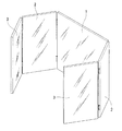
以下、図面に基づき、本発明の実施形態を説明する。図1および図2は、第1の実施形態を示す。この鏡台は、図1に示すように、正面鏡1の両側に、正面鏡1側を回動中心として垂直軸の回りに回動し、両側辺が平行な平板状の袖板部材としての袖鏡2を設けた既存の3面鏡を利用したものであり、両方の袖鏡2の正面鏡1と反対側に、袖鏡2側を回動中心として垂直軸の回りに回動する背面鏡3が取り付け部品として取り付けられている。
Hereinafter, embodiments of the present invention will be described with reference to the drawings. 1 and 2 show a first embodiment. As shown in FIG. 1, this lens mount rotates on the both sides of the
前記背面鏡3は、図2(a)に示すように、袖鏡2の正面鏡1と反対側の端面に蝶番4で取り付けられ、袖鏡2の表面側へ重ねるように折り畳まれるようになっており、表面3aと裏面3bの両方が鏡面とされている。したがって、袖鏡2の表面側へ重ねられたときには、背面鏡3の裏面3bが3面鏡の袖鏡の役割をするようになっている。
As shown in FIG. 2 (a), the
図2(b)は、前記袖鏡2と背面鏡3を正面鏡1とで横断面が略コ字状を形成するように回動させた状態を示す。この状態で、正面鏡1側に向けられる背面鏡3の表面3aに、鏡台の前の人Aの背面が映される。
FIG. 2B shows a state in which the
上述した第1の実施形態では、3面鏡の両側の袖鏡2に背面鏡3を取り付けたが、いずれか一方の袖鏡2のみに背面鏡3を取り付けることもでき、3面鏡を片側のみに袖鏡2を有する2面鏡とすることもできる。
In the first embodiment described above, the
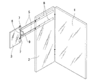
図3乃至図5は、第2の実施形態を示す。この鏡台は、図3に示すように、正面鏡1の片側に、正面鏡1側を回動中心として垂直軸の回りに回動する袖板部材としての袖鏡2を設け、この袖鏡2の正面鏡1と反対側に、袖鏡2側を回動中心として垂直軸の回りに回動する背面鏡3を設けたものである。
3 to 5 show a second embodiment. As shown in FIG. 3, this lens mount is provided with a
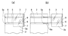
前記背面鏡3は、図4(a)および図5(a)に示すように、袖鏡2よりも小さい面積のものとされ、袖鏡2の裏面側に沿って水平方向へスライドさせる上下一対のスライドバー5の先端に取り付けられた垂直な軸部材6に、軸部材6に回動可能に外嵌されたヒンジ7で取り付けられている。したがって、スライドバー5を袖鏡2の裏面側へ押し込んで、背面鏡3を回動させることにより、背面鏡3を袖鏡2の裏面側の上部へ重ねるように折り畳むことができる。この背面鏡3は、表面3aのみが鏡面とされており、各スライドバー5は、袖鏡2の裏面に設けられたガイド溝8に案内されてスライドするようになっている。また、軸部材6には、スライドバー5を引き出すための把手9が取り付けられている。
As shown in FIGS. 4A and 5A, the
図4(b)は、前記スライドバー5をスライドさせて、背面鏡3を袖鏡2の裏面側から引き出した状態を示す。ガイド溝8の正面鏡1と反対側の部分には、スライドバー5を抱え込むように内向きに張り出す庇部8aが設けられ、スライドバー5の基端にはガイド溝8から突出する突出部5aが設けられており、この突出部5aが庇部8aの端に係止されて、スライドバー5は2/3程度の長さが引き出し可能とされている。
FIG. 4B shows a state in which the
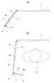
図5(b)は、前記袖鏡2の裏面側から引き出した背面鏡3を軸部材6の回りに回動させて、袖鏡2およびスライドバー5と背面鏡3を正面鏡1とで横断面が略コ字状を形成するようにした状態を示す。背面鏡3は、表面3aが軸部材6の把手9に当接されて、回動位置を位置決めされている。この状態で、正面鏡1側に向けられる背面鏡3の表面3aに、鏡台の前の人Aの上部の背面が映される。この実施形態では、背面鏡3がスライドバー5によって人Aの後方に引き出されるので、正面鏡1との間に人Aが介在する十分なスペースが開けられる。
FIG. 5B shows the
図6(a)、(b)は、第3の実施形態を示す。この鏡台は、第1の実施形態のものと同様に、正面鏡1の両側に袖鏡2を設けた既存の3面鏡を利用したものである。各袖鏡2の正面鏡1と反対側には、垂直軸の回りに回動して袖鏡2の裏面側へ水平方向に折り畳んで重ねられる折り畳み部材10が蝶番4aで取り付けられ、これらの折り畳み部材10の展開先端側に、垂直軸の回りに回動して袖鏡2の裏面側へ折り畳まれる背面鏡3が蝶番4bで取り付けられており、折り畳み部材10と背面鏡3が取り付け部品とされている。
FIGS. 6A and 6B show a third embodiment. Similar to the first embodiment, this table uses an existing three-sided mirror in which sleeve mirrors 2 are provided on both sides of the
この実施形態では、図6(b)に示すように、折り畳み部材10と背面鏡3を袖鏡2の裏面側から展開することにより、正面鏡1側に向けられる背面鏡3と正面鏡1との間に、人Aが介在する十分なスペースが開けられる。なお、各背面鏡3は、人Aの背面に向けられる表面3aのみが鏡面とされ、各折り畳み部材10は、人Aに向けられる内側面が鏡面10aとされている。また、袖鏡2、背面鏡3および折り畳み部材10の幅寸法は同一寸法とされている。
In this embodiment, as shown in FIG. 6 (b), the folding
第3の実施形態では、袖鏡の裏面側へ折り畳まれる折り畳み部材を1枚としたが、2枚以上の折り畳み部材をヒンジ等で水平方向に展開可能に連結し、これらの複数枚の折り畳み部材を介して、背面鏡を袖鏡の裏面側または表面側へ折り畳むように取り付けることもできる。また、袖鏡、背面鏡および折り畳み部材の幅寸法を同一寸法に合致させたが、これらの幅寸法は互いに異なる寸法としてもよい。 In the third embodiment, one folding member is folded to the back side of the sleeve mirror, but two or more folding members are connected so as to be deployable in the horizontal direction by a hinge or the like, and a plurality of these folding members are connected. It is also possible to attach the rear-view mirror so as to be folded to the back side or the front side of the sleeve mirror. Moreover, although the width dimension of the sleeve mirror, the rear-view mirror, and the folding member is matched with the same dimension, these width dimensions may be different from each other.
1 正面鏡
2 袖鏡
3 背面鏡
3a 表面
3b 裏面
4、4a、4b 蝶番
5 スライドバー
5a 突出部
6 軸部材
7 ヒンジ
8 ガイド溝
8a 庇部
9 把手
10 折り畳み部材
10a 鏡面
DESCRIPTION OF
Claims (6)
Priority Applications (1)
| Application Number | Priority Date | Filing Date | Title |
|---|---|---|---|
| JP2009135888A JP2010253233A (en) | 2009-04-03 | 2009-06-05 | Dressing table |
Applications Claiming Priority (2)
| Application Number | Priority Date | Filing Date | Title |
|---|---|---|---|
| JP2009091003 | 2009-04-03 | ||
| JP2009135888A JP2010253233A (en) | 2009-04-03 | 2009-06-05 | Dressing table |
Publications (1)
| Publication Number | Publication Date |
|---|---|
| JP2010253233A true JP2010253233A (en) | 2010-11-11 |
Family
ID=43314842
Family Applications (1)
| Application Number | Title | Priority Date | Filing Date |
|---|---|---|---|
| JP2009135888A Pending JP2010253233A (en) | 2009-04-03 | 2009-06-05 | Dressing table |
Country Status (1)
| Country | Link |
|---|---|
| JP (1) | JP2010253233A (en) |
Cited By (3)
| Publication number | Priority date | Publication date | Assignee | Title |
|---|---|---|---|---|
| CN109198914A (en) * | 2018-09-21 | 2019-01-15 | 九牧厨卫股份有限公司 | A kind of cover plate assembly and cabinet body |
| CN109640737A (en) * | 2016-08-19 | 2019-04-16 | 谢尔盖·乔吉维奇·比留科夫 | A device used to reflect the external appearance of a person |
| CN109907543A (en) * | 2019-04-04 | 2019-06-21 | 广州欧派集成家居有限公司 | A kind of dressing cabinet |
Citations (3)
| Publication number | Priority date | Publication date | Assignee | Title |
|---|---|---|---|---|
| JPS4964199A (en) * | 1972-10-30 | 1974-06-21 | ||
| JPS50154199A (en) * | 1974-04-30 | 1975-12-11 | ||
| JPH0339437A (en) * | 1989-07-07 | 1991-02-20 | Showa Alum Corp | Aluminum alloy foil for cathode chemical condenser |
-
2009
- 2009-06-05 JP JP2009135888A patent/JP2010253233A/en active Pending
Patent Citations (3)
| Publication number | Priority date | Publication date | Assignee | Title |
|---|---|---|---|---|
| JPS4964199A (en) * | 1972-10-30 | 1974-06-21 | ||
| JPS50154199A (en) * | 1974-04-30 | 1975-12-11 | ||
| JPH0339437A (en) * | 1989-07-07 | 1991-02-20 | Showa Alum Corp | Aluminum alloy foil for cathode chemical condenser |
Cited By (4)
| Publication number | Priority date | Publication date | Assignee | Title |
|---|---|---|---|---|
| CN109640737A (en) * | 2016-08-19 | 2019-04-16 | 谢尔盖·乔吉维奇·比留科夫 | A device used to reflect the external appearance of a person |
| CN109198914A (en) * | 2018-09-21 | 2019-01-15 | 九牧厨卫股份有限公司 | A kind of cover plate assembly and cabinet body |
| CN109907543A (en) * | 2019-04-04 | 2019-06-21 | 广州欧派集成家居有限公司 | A kind of dressing cabinet |
| CN109907543B (en) * | 2019-04-04 | 2021-03-19 | 广州欧派集成家居有限公司 | Dressing cabinet |
Similar Documents
| Publication | Publication Date | Title |
|---|---|---|
| JP2010253233A (en) | Dressing table | |
| TWI253289B (en) | Electrical device with hanging mechanism | |
| KR100893387B1 (en) | Folding chair with table | |
| KR200394832Y1 (en) | A hinged mirror | |
| JP4261499B2 (en) | Vehicle table structure | |
| KR100545799B1 (en) | Backrest chair | |
| JP3782403B2 (en) | Three-sided mirror | |
| JP6276974B2 (en) | Folding chair | |
| KR20130093199A (en) | Mirror assembly | |
| JP5393865B2 (en) | Folding chair | |
| JP3158591U (en) | Three-sided mirror | |
| JP3196197U (en) | Folding hand mirror | |
| JP3112617U (en) | Three-sided mirror that can see the back of the head | |
| CN109407322A (en) | Collapsible head-mounted display | |
| KR200390432Y1 (en) | Folding type chair | |
| JP2010077604A (en) | Self-standing fan-like decorative member | |
| KR200425221Y1 (en) | Lecture desk | |
| JP2012090666A (en) | Mirror device | |
| CN211609011U (en) | Portable folding mirror | |
| JP3135867U (en) | Folding portable reversing mirror | |
| KR200343463Y1 (en) | Reading stand | |
| JP2009039338A (en) | Mirror cabinet | |
| JPS5933375B2 (en) | makeup mirror device | |
| JP2018100182A (en) | Elevator landing side door unlocking device | |
| JP2005304914A (en) | Cosmetic container for eye makeup |
Legal Events
| Date | Code | Title | Description |
|---|---|---|---|
| A131 | Notification of reasons for refusal |
Effective date: 20110823 Free format text: JAPANESE INTERMEDIATE CODE: A131 |
|
| A02 | Decision of refusal |
Effective date: 20120110 Free format text: JAPANESE INTERMEDIATE CODE: A02 |