JP2010250024A - Toner for nonmagnetic single component development - Google Patents
Toner for nonmagnetic single component development Download PDFInfo
- Publication number
- JP2010250024A JP2010250024A JP2009098486A JP2009098486A JP2010250024A JP 2010250024 A JP2010250024 A JP 2010250024A JP 2009098486 A JP2009098486 A JP 2009098486A JP 2009098486 A JP2009098486 A JP 2009098486A JP 2010250024 A JP2010250024 A JP 2010250024A
- Authority
- JP
- Japan
- Prior art keywords
- hot air
- raw material
- injection nozzle
- toner particles
- toner
- Prior art date
- Legal status (The legal status is an assumption and is not a legal conclusion. Google has not performed a legal analysis and makes no representation as to the accuracy of the status listed.)
- Pending
Links
Images


Abstract
Description
本発明は、たとえば複写機、プリンタなどの電子写真方式によって画像を形成する画像形成装置に用いられる非磁性一成分現像用トナーに関する。 The present invention relates to a non-magnetic one-component developing toner used in an image forming apparatus for forming an image by an electrophotographic method such as a copying machine or a printer.
コンピュータ、OA(Office Automation)機器などの性能向上に伴い、情報の出力機器として、高解像度の文字画像および図形画像などの画像を出力できる各種プリンタ、複写機が市販されている。これらの機器における画像形成方法としては、像担持体に静電荷像を形成し、電子写真用トナー(以下、単に「トナー」ということがある)を用いて静電荷像を現像してトナー像とし、このトナー像を記録媒体に転写して定着させる、いわゆる電子写真方式が広く使用されている。 As the performance of computers, OA (Office Automation) devices and the like improves, various printers and copiers capable of outputting images such as high-resolution character images and graphic images are commercially available as information output devices. As an image forming method in these apparatuses, an electrostatic charge image is formed on an image carrier, and the electrostatic charge image is developed using a toner for electrophotography (hereinafter sometimes simply referred to as “toner”) to form a toner image. A so-called electrophotographic system in which this toner image is transferred to a recording medium and fixed is widely used.
電子写真用トナーは、結着剤、着色剤、離型剤および帯電制御剤などを含有する、微細な粒子状のものである。 The electrophotographic toner is in the form of fine particles containing a binder, a colorant, a release agent, a charge control agent, and the like.
電子写真用トナーの製造方法の一種として、粉砕法が知られている。粉砕法は、まず結着剤、離型剤、着色剤および荷電制御剤などのトナー原料を混合して溶融混練し、得られた溶融混練物を冷却した後、粉砕して分級することによってトナー粒子を得る方法であり、比較的簡易な設備で、効率良く電子写真用トナーを製造できるという特長を有する。粉砕法では、より詳細には分級の後にさらにトナー粒子に流動化剤および抵抗制御剤などの外添剤を外添し、混合機で混合してトナー粒子表面に外添剤を付着させて電子写真用トナーを得る。 A pulverization method is known as a kind of method for producing an electrophotographic toner. In the pulverization method, first, toner materials such as a binder, a release agent, a colorant and a charge control agent are mixed and melt-kneaded, and the resulting melt-kneaded product is cooled, then pulverized and classified. This is a method for obtaining particles, and has an advantage that an electrophotographic toner can be efficiently produced with relatively simple equipment. In the pulverization method, more specifically, after classification, an external additive such as a fluidizing agent and a resistance control agent is further externally added to the toner particles, and mixed with a mixer to adhere the external additive to the surface of the toner particles. A photographic toner is obtained.
このように溶融混練物を粉砕することによってトナー粒子を生成して製造される電子写真用トナーは、粒子の形状が不定形となり、流動性が充分でないという問題を有している。このようなトナーを用いると、たとえば非磁性一成分現像法では、現像スリーブへのトナーの搬送性が充分でなくなり、追従不良やジッタが発生しやすくなる。「追従不良」とは、現像スリーブの回転にトナー補給(供給)が追従できず、画像濃度が低下する現象のことである。「ジッタ」とは、機械的負荷により現像スリーブやトナーの搬送速度が乱れ、画像に縞状の濃淡が発生する現象のことである。 Thus, the electrophotographic toner produced by producing toner particles by pulverizing the melt-kneaded product has a problem that the shape of the particles becomes irregular and the fluidity is not sufficient. When such toner is used, for example, in the non-magnetic one-component developing method, the toner transportability to the developing sleeve is not sufficient, and tracking failure and jitter are likely to occur. “Following tracking” refers to a phenomenon in which toner replenishment (supply) cannot follow the rotation of the developing sleeve and the image density decreases. “Jitter” is a phenomenon in which the developing sleeve and toner transport speed are disturbed by a mechanical load, and stripes of light and shade are generated in an image.
そこで、本件発明者らは、粉砕によって粒子化されたトナー粒子を、特定の熱風処理装置を用いて特定条件下で加熱処理することによって、トナー粒子を流動しやすい形状に成形することができ、充分な流動性を有する電子写真用トナーが得られることを見出した(たとえば、特許文献1参照)。 Therefore, the present inventors can form the toner particles into a shape that is easy to flow by heat-treating the toner particles, which have been pulverized, under specific conditions using a specific hot-air treatment device, It has been found that an electrophotographic toner having sufficient fluidity can be obtained (for example, see Patent Document 1).
特許文献1に記載の技術によれば、電子写真用トナーの流動性を向上させることは可能であるが、熱処理によってブリードした離型剤により、帯電ブレードおよび現像ローラー等を汚染するため、形成される画像の濃度ムラや帯電不良によるかぶり、さらにはトナー消費量の増加などの問題が発生しやすくなる。そこで、このような問題の発生しない、さらなる良好な性能を有する電子写真用トナーが望まれている。
According to the technique described in
本発明は上記状況に鑑みてなされたものであり、本発明の目的は、粉砕法によって粒子化されたトナー粒子を利用しても、充分な流動性を有し、かつ帯電ブレードおよび現像ローラー等を汚染せずに画像の濃度ムラや帯電不良によるかぶりを防止する非磁性一成分現像用トナーを提供することである。 The present invention has been made in view of the above situation, and an object of the present invention is to have sufficient fluidity even when toner particles made into particles by a pulverization method are used, and to have a charging blade, a developing roller, etc. The present invention provides a non-magnetic one-component developing toner that prevents fog due to image density unevenness or poor charging without contaminating the toner.
本発明は、少なくとも結着剤および着色剤、離型剤、荷電調整剤を含有し、粉砕法によって得られた第1トナー粒子10〜40質量部と、
熱処理槽、熱処理槽の内部空間に向けて熱風を噴射する熱風噴射ノズル、および熱風噴射ノズルから噴射される熱風に向けて原料を噴射する原料噴射ノズルを備えた熱処理装置を用いて、前記第1トナー粒子を前記原料として熱処理して得られた第2トナー粒子100質量部と、
流動化剤とを混合してなることを特徴とする非磁性一成分現像用トナーである。
The present invention includes at least a binder, a colorant, a release agent, and a charge control agent, and 10 to 40 parts by mass of first toner particles obtained by a pulverization method;
The heat treatment tank includes a heat treatment apparatus including a heat treatment tank, a hot air injection nozzle that injects hot air toward the internal space of the heat treatment tank, and a raw material injection nozzle that injects a raw material toward the hot air injected from the hot air injection nozzle. 100 parts by mass of second toner particles obtained by heat treatment using toner particles as the raw material;
A toner for non-magnetic one-component development, wherein the toner is mixed with a fluidizing agent.
また本発明は、前記第2トナー粒子は、
上部に冷却用エアを取入れるためのエア取入口が形成され、上部から内部空間に前記第2トナー粒子および熱風が供給される熱風処理槽と、熱風処理槽の上部から内部空間に向けて熱風を噴射する熱風噴射ノズルと、熱風噴射ノズルから噴射される熱風に向けて原料を噴射する原料噴射ノズルであって、原料が噴射される原料出口が形成される下端開口部が、熱風噴射ノズルの熱風が噴射される熱風出口が形成される下端開口部の内方側に、熱風噴射ノズルの下端開口部よりも上方に位置するように設けられる原料噴射ノズルと、原料噴射ノズルから離隔して原料噴射ノズルを囲繞するように設けられ、内部に冷媒が流下する流路が形成される冷却ジャケットを含み、原料噴射ノズルと熱風噴射ノズルとを断熱する断熱機構と、原料噴射ノズルの下端開口部の下方に原料噴射ノズルから離隔して設けられる衝突部材と、原料噴射ノズルの外表面部と断熱機構の冷却ジャケットの内表面部とによって形成されるエア噴射流路の下端の開口から、衝突部材の原料噴射ノズルの下端開口部を臨む表面部に向けて分散用エアを噴射するエア噴射手段と、を備える熱風処理装置を用いて、
熱風噴射ノズルから熱風処理槽内に供給される熱風の温度Ta[℃]および風量La[lt/min、0℃、1気圧]、原料噴射ノズルから熱風処理槽内に供給される原料混合物の供給速度Wf[g/min]、ならびにトナー粒子の2分の1(1/2)降下温度Tm[℃]が、下記式(1)および(2)を満足する条件下で、加熱処理されることを特徴とする。
Tm<Ta×La/(La+Wf×1.4[lt/g])<Tm×3 …(1)
0.08[g/lt]×La<Wf<0.5[g/lt]×La …(2)
In the present invention, the second toner particles may be
An air inlet for taking in cooling air is formed in the upper part, and a hot air treatment tank in which the second toner particles and hot air are supplied from the upper part to the internal space, and hot air from the upper part of the hot air treatment tank toward the internal space A hot air injection nozzle for injecting a raw material and a raw material injection nozzle for injecting a raw material toward the hot air injected from the hot air injection nozzle, wherein a lower end opening in which a raw material outlet through which the raw material is injected is formed is A raw material injection nozzle provided so as to be located above the lower end opening of the hot air injection nozzle on the inner side of the lower end opening where the hot air outlet from which hot air is injected is formed, and the raw material is separated from the raw material injection nozzle A heat insulation mechanism that includes a cooling jacket that is provided so as to surround the injection nozzle and in which a flow path through which a refrigerant flows is formed, and that insulates the raw material injection nozzle from the hot air injection nozzle; and a raw material injection nozzle The lower end opening of the air injection flow path formed by the collision member provided below the lower end opening of the material and spaced from the raw material injection nozzle, the outer surface portion of the raw material injection nozzle, and the inner surface portion of the cooling jacket of the heat insulation mechanism From the hot air treatment device comprising, air injection means for injecting the dispersion air toward the surface portion facing the lower end opening of the raw material injection nozzle of the collision member,
Supply of the raw material mixture supplied from the raw material injection nozzle into the hot air treatment tank, temperature Ta [° C.] and air volume La [lt / min, 0 ° C., 1 atm] supplied from the hot air injection nozzle into the hot air treatment tank Heat treatment is performed under conditions where the speed Wf [g / min] and the half (1/2) temperature drop Tm [° C.] of the toner particles satisfy the following formulas (1) and (2). It is characterized by.
Tm <Ta × La / (La + Wf × 1.4 [lt / g]) <Tm × 3 (1)
0.08 [g / lt] × La <Wf <0.5 [g / lt] × La (2)
本発明によれば、少なくとも結着剤および着色剤、離型剤、荷電調整剤を含有し、粉砕法によって得られた第1トナー粒子10〜40質量部と、特定の熱処理装置を用いて、前記第1トナー粒子熱処理して得られた第2トナー粒子100質量部と、流動化剤とを混合することで得られる非磁性一成分現像用トナーである。 According to the present invention, at least a binder, a colorant, a release agent, a charge control agent, and 10 to 40 parts by mass of first toner particles obtained by a pulverization method, and a specific heat treatment apparatus are used. This is a non-magnetic one-component developing toner obtained by mixing 100 parts by mass of second toner particles obtained by heat treatment of the first toner particles and a fluidizing agent.
これにより、粉砕法によって粒子化されたトナー粒子を利用しても、充分な流動性を有し、かつ帯電ブレードおよび現像ローラー等を汚染せずに画像の濃度ムラや帯電不良によるかぶりを防止することができる。 As a result, even when toner particles that have been made into particles by the pulverization method are used, they have sufficient fluidity and prevent fogging due to uneven density of the image or poor charging without contaminating the charging blade and developing roller. be able to.
また本発明によれば、熱風処理装置では、熱風処理槽の上部から内部空間に向けて熱風噴射ノズルの熱風出口から熱風が噴射され、この熱風に向けて原料噴射ノズルの原料出口から第1トナー粒子が噴射される。原料噴射ノズルから噴射された第1トナー粒子は、衝突部材に衝突して熱風中に分散されるとともに、エア噴射手段によってエア噴射流路から噴射される分散用エアによって熱風中に分散され、熱風によって加熱処理される。原料噴射ノズルの原料出口が形成される下端開口部は、熱風噴射ノズルの熱風出口が形成される下端開口部の内方側に、熱風噴射ノズルの下端開口部よりも上方に位置するように設けられているので、原料噴射ノズルから噴射された第1トナー粒子は、熱風噴射ノズルから噴射される熱風と直ちに接触し、加熱処理される。原料噴射ノズルと熱風噴射ノズルとは、内部の流路に冷媒が流下する冷却ジャケットを含む断熱機構によって断熱されているので、原料噴射ノズル内を流動する第1トナー粒子が、熱風噴射ノズル内を流動する熱風との熱交換によって昇温することが防止される。加熱処理された第1トナー粒子は、熱風処理槽の上部に形成されたエア取入口を通して熱風処理槽内に流入する冷却用エアによって冷却される。 According to the present invention, in the hot air processing apparatus, hot air is injected from the hot air outlet of the hot air injection nozzle toward the internal space from the upper part of the hot air processing tank, and the first toner is supplied from the raw material outlet of the raw material injection nozzle toward the hot air. Particles are jetted. The first toner particles ejected from the raw material ejection nozzle collide with the collision member and are dispersed in the hot air, and also dispersed in the hot air by the dispersion air ejected from the air ejection flow path by the air ejecting means. Is heated. The lower end opening where the raw material outlet of the raw air injection nozzle is formed is provided on the inner side of the lower end opening where the hot air outlet of the hot air injection nozzle is formed so as to be positioned above the lower end opening of the hot air injection nozzle. Therefore, the first toner particles ejected from the raw material ejecting nozzle are immediately brought into contact with the hot air ejected from the hot air ejecting nozzle and subjected to heat treatment. Since the raw material injection nozzle and the hot air injection nozzle are insulated by a heat insulation mechanism including a cooling jacket in which the refrigerant flows into the internal flow path, the first toner particles flowing in the raw material injection nozzle are moved through the hot air injection nozzle. It is prevented that the temperature is raised by heat exchange with the flowing hot air. The heat-treated first toner particles are cooled by cooling air flowing into the hot air treatment tank through an air intake formed in the upper part of the hot air treatment tank.
この熱風処理装置における加熱処理は、熱風噴射ノズルから噴射される熱風の温度(以下「熱風温度」ということがある)Ta[℃]および風量(以下「熱風風量」ということがある)La[lt/min、0℃、1気圧]、原料噴射ノズルから噴射される原料混合物の供給速度(以下「原料供給速度」ということがある)Wf[g/min]、ならびにトナー粒子の1/2降下温度Tm[℃]が、前述の式(1)および(2)を満足する条件下で行なわれる。 The heat treatment in this hot air treatment apparatus is performed by the temperature of hot air ejected from the hot air jet nozzle (hereinafter also referred to as “hot air temperature”) Ta [° C.] and the air volume (hereinafter sometimes referred to as “hot air air volume”) La [lt. / Min, 0 ° C., 1 atm], feed rate of the raw material mixture ejected from the raw material jet nozzle (hereinafter sometimes referred to as “raw material feed rate”) Wf [g / min], and 1/2 drop temperature of the toner particles Tm [° C.] is performed under the conditions satisfying the above-mentioned formulas (1) and (2).
熱風中におけるトナー粒子の表面温度Tt[℃]は、熱風温度Ta、熱風風量Laおよび原料供給速度Wfと相関しており、式(1)の中辺「Ta×La/(La+Wf×1.4[lt/g])」で表すことができる。式(1)の中辺の値がトナー粒子の1/2降下温度Tm以下であると、トナー粒子の表面温度Ttが低過ぎてトナー粒子の表面が充分に溶融されず、成形されにくいので、加熱処理によるトナーの流動性の向上効果が得られないか、または効果が得られても小さいものとなる。式(1)の中辺の値がトナー粒子の1/2降下温度Tmの3倍以上であると、トナー粒子の表面温度Ttが高過ぎてトナー粒子の表面が過度に溶融し、トナー粒子同士が融着しやすくなり、またシリカ微粒子がトナー粒子表面に固着して流動性が低下する。式(1)を満足する条件下で加熱処理を行なうことによって、トナー粒子の表面温度Ttを好適な範囲にすることができるので、トナー粒子同士の融着およびシリカ微粒子のトナー粒子表面への固着を抑え、流動性をより確実に向上させることができる。 The surface temperature Tt [° C.] of the toner particles in the hot air correlates with the hot air temperature Ta, the hot air flow rate La, and the raw material supply speed Wf, and the middle side of the formula (1) “Ta × La / (La + Wf × 1.4). [Lt / g]) ”. If the value of the middle side of the formula (1) is equal to or lower than the ½ drop temperature Tm of the toner particles, the surface temperature Tt of the toner particles is too low and the surface of the toner particles is not sufficiently melted and is difficult to be molded. The effect of improving the fluidity of the toner by the heat treatment cannot be obtained, or even if the effect is obtained, it becomes small. If the value of the middle side of the formula (1) is 3 times or more of the ½ drop temperature Tm of the toner particles, the surface temperature Tt of the toner particles is too high and the surface of the toner particles melts excessively. Are liable to be fused, and the silica fine particles are fixed to the surface of the toner particles and the fluidity is lowered. By performing the heat treatment under the condition satisfying the formula (1), the surface temperature Tt of the toner particles can be adjusted to a suitable range, so that the toner particles are fused and the silica fine particles are fixed on the toner particle surface. And the fluidity can be improved more reliably.
また熱風中における原料混合物の濃度は、式(2)の中辺である原料供給速度Wfおよび熱風風量Laと相関している。原料供給速度Wfが0.08La以下であると、熱風中における原料混合物の濃度が低くなり過ぎ、単位時間あたりに加熱処理することのできる原料混合物の量が過度に少なくなるので、生産性が低くなる。原料供給速度Wfが0.5La以上であると、熱風中における原料混合物の濃度が高くなり過ぎ、原料混合物を均一に加熱処理することが困難になり、またトナー粒子同士の融着が発生する。式(2)を満足する条件下で加熱処理を行なうことによって、熱風中における原料混合物の濃度を好適な範囲にすることができるので、原料混合物をより均一に加熱処理し、均質なトナーを得ることができ、またトナー粒子同士の融着を抑え、流動性をより確実に向上させることができる。また生産性が過度に低くなることを防ぐことができる。 Moreover, the density | concentration of the raw material mixture in a hot air correlates with the raw material supply speed | rate Wf and the hot air flow volume La which are the middle sides of Formula (2). When the raw material supply speed Wf is 0.08 La or less, the concentration of the raw material mixture in the hot air becomes too low, and the amount of the raw material mixture that can be heat-treated per unit time becomes excessively small, so the productivity is low. Become. When the raw material supply speed Wf is 0.5 La or more, the concentration of the raw material mixture in the hot air becomes too high, and it becomes difficult to uniformly heat the raw material mixture, and the toner particles are fused. By performing the heat treatment under the condition satisfying the formula (2), the concentration of the raw material mixture in the hot air can be adjusted to a suitable range, so that the raw material mixture is more uniformly heated to obtain a homogeneous toner. In addition, the fusion between the toner particles can be suppressed, and the fluidity can be improved more reliably. Moreover, it can prevent that productivity becomes low too much.
本発明の電子写真用トナー(以下、単に「トナー」ということがある)は、粉砕によって粒子化された第1トナー粒子と、この第1トナー粒子に対して、流動化剤を添加し混合して得られた原料混合物を、後述する図1および図2に示す熱風処理装置1を用いて加熱処理して得られる第2トナー粒子とを混合して得られたものである。
The electrophotographic toner of the present invention (hereinafter sometimes simply referred to as “toner”) is mixed with first toner particles that have been pulverized and a fluidizing agent added to the first toner particles. The raw material mixture obtained in this manner is obtained by mixing the second toner particles obtained by heat treatment using the hot
[粒子生成工程]
粒子生成工程では、粉砕法によって第1トナー粒子を生成する。第1トナー粒子は、結着剤および着色剤を含有し、本実施形態ではさらに荷電調整剤、離型剤を含有する。第1トナー粒子を構成する材料(以下「トナー粒子の構成材料」ということがある)はこれに限定されない。
[Particle generation process]
In the particle generation step, first toner particles are generated by a pulverization method. The first toner particles contain a binder and a colorant. In the present embodiment, the first toner particles further contain a charge adjusting agent and a release agent. The material constituting the first toner particles (hereinafter also referred to as “the constituent material of the toner particles”) is not limited to this.
第1トナー粒子を構成する結着剤の材料としては、特に制限はなく、従来公知のものが使用でき、具体的には、ポリスチレン、スチレン−アクリル酸メチル共重合体、スチレン−アクリロニトリル共重合体などのスチレン系共重合体、ポリエステル樹脂、エポキシ樹脂などの樹脂材料を挙げることができる。これらの結着剤の材料は、1種を単独で用いることができ、また2種以上を組み合わせて用いることもできる。これらの中でも、着色しやすく、鮮明な色彩のトナーが得られる点から、ポリエステル樹脂を用いることが特に好適である。したがって本実施形態ではポリエステル樹脂から成る結着剤を用いる。 The material of the binder constituting the first toner particles is not particularly limited and conventionally known materials can be used. Specifically, polystyrene, styrene-methyl acrylate copolymer, styrene-acrylonitrile copolymer can be used. Examples thereof include resin materials such as styrene copolymers, polyester resins, and epoxy resins. These binder materials can be used singly or in combination of two or more. Among these, it is particularly preferable to use a polyester resin because it is easy to be colored and a toner having a clear color can be obtained. Therefore, in this embodiment, a binder made of a polyester resin is used.
第1トナー粒子を構成する着色剤の材料としては、特に制限はなく、従来公知のものが使用できる。具体的には、黒色の着色剤の材料としては、たとえばカーボンブラック、黒色を呈する磁性粉などを挙げることができ、シアン色の着色剤の材料としては、たとえば銅フタロシアニン、メチレンブルー、ビクトリアブルーなどを挙げることができ、マゼンタ色の着色剤の材料としては、たとえばローダミン染料、ジメチルキナクリドン、ジクロロキナクリドン、カーミンレッドなどを挙げることができ、イエロー色の着色剤の材料としては、たとえばベンジジンイエロー、クロムイエロー、ナフトールイエロー、ジスアゾイエローなどを挙げることができる。 The material for the colorant constituting the first toner particles is not particularly limited, and conventionally known materials can be used. Specifically, examples of the black colorant material include carbon black and magnetic powder exhibiting black color. Examples of the cyan colorant material include copper phthalocyanine, methylene blue, and Victoria blue. Examples of magenta colorant materials include rhodamine dyes, dimethylquinacridone, dichloroquinacridone, and carmine red. Examples of yellow colorant materials include benzidine yellow and chrome yellow. Naphthol yellow, disazo yellow and the like.
本実施形態において第1トナー粒子は、離型剤を含有する。第1トナー粒子に離型剤を含有させることによって、電子写真用トナーの耐オフセット性を向上させ、オフセット現象を起こりにくくすることができる。離型剤の材料としては、特に制限はなく、従来公知のものが使用でき、具体的には、たとえば、ポリエチレン、ポリプロピレンなどのポリオレフィンワックス、カルナバワックス、ライスワックス、サゾールワックス、モンタン系エステルワックスなどを挙げることができる。 In the present embodiment, the first toner particles contain a release agent. By including a release agent in the first toner particles, the offset resistance of the electrophotographic toner can be improved and the offset phenomenon can be made difficult to occur. The material of the release agent is not particularly limited, and conventionally known materials can be used. Specifically, for example, polyolefin wax such as polyethylene and polypropylene, carnauba wax, rice wax, sazol wax, montan ester wax And so on.
また第1トナー粒子は、荷電調整剤を含有する。第1トナー粒子に荷電調整剤を含有させることによって、電子写真用トナーを効率的に帯電させることができる。荷電調整剤の材料としては、特に制限はなく、従来公知のものが使用でき、具体的には、ニグロシン、塩基性染料、モノアゾ染料などの金属錯体、サリチル酸およびジカルボン酸などのカルボン酸、クロムおよび鉄などの金属との金属錯体、有機染料などを挙げることができる。 The first toner particles contain a charge adjusting agent. By including a charge adjusting agent in the first toner particles, the electrophotographic toner can be efficiently charged. The material for the charge control agent is not particularly limited, and conventionally known materials can be used. Specifically, nigrosine, basic dyes, metal complexes such as monoazo dyes, carboxylic acids such as salicylic acid and dicarboxylic acid, chromium and Examples include metal complexes with metals such as iron, organic dyes, and the like.
第1トナー粒子は、本実施形態では粉砕法によって粒子化されたものであり、粒子生成工程において、上記構成材料を、ヘンシェルミキサなどの混合機を用いて混合し、二軸押出機などの混練機を用いて混練した後、得られた混練物を粉砕機によって粉砕することによって得られる。 In the present embodiment, the first toner particles are made into particles by a pulverization method. In the particle generation step, the constituent materials are mixed using a mixer such as a Henschel mixer, and then kneaded such as a twin screw extruder. After kneading with a machine, the obtained kneaded product is obtained by pulverizing with a pulverizer.
混練物の粉砕に用いる粉砕機としては、特に制限はなく、たとえばジェットミル、ターボミルなどを挙げることができる。これらの中でも、ロータを用いて粉砕するロータ式粉砕機を使用することが好ましい。 The pulverizer used for pulverizing the kneaded product is not particularly limited, and examples thereof include a jet mill and a turbo mill. Among these, it is preferable to use a rotor-type pulverizer that pulverizes using a rotor.
第1トナー粒子は、後述する加熱処理工程における加熱処理によって、複数の粒子が融着することが少なく、個々に表面が平滑な第2トナー粒子となるので、加熱処理後の第2トナー粒子の大きさは、粒子生成工程で得られる第1トナー粒子の大きさによって決定される。加熱処理工程における加熱処理後の第2トナー粒子は、体積平均粒子径が4μm以上15μm以下であることが好ましく、6μm以上10μm以下であることがより好ましい。したがって、加熱処理工程に供する第1トナー粒子としては、粒子生成工程における粉砕によって得られる第1トナー粒子から、加熱処理後における第2トナー粒子の体積平均粒子径の好適な範囲として前述した範囲内に体積平均粒子径を有するものを分級によって分取して使用することが好ましい。 The first toner particles are less likely to be fused by a heat treatment in a heat treatment step to be described later, and individually become second toner particles having a smooth surface. The size is determined by the size of the first toner particles obtained in the particle generation step. The second toner particles after the heat treatment in the heat treatment step preferably have a volume average particle size of 4 μm to 15 μm, and more preferably 6 μm to 10 μm. Accordingly, the first toner particles used in the heat treatment step are within the above-described range as the preferred range of the volume average particle diameter of the second toner particles after the heat treatment from the first toner particles obtained by pulverization in the particle generation step. Those having a volume average particle diameter are preferably used by classification.
[流動化剤混合工程]
本工程では、粒子生成工程で得られた第1トナー粒子と流動化剤とを混合して原料混合物を得る。流動化剤としては、特に制限はなく、従来公知のものが使用でき、具体的には、シリカ微粒子、酸化チタン微粒子などを挙げることができ、本実施形態では、シリカ微粒子を用いる。
[Fluidizing agent mixing process]
In this step, the first toner particles obtained in the particle generation step and the fluidizing agent are mixed to obtain a raw material mixture. The fluidizing agent is not particularly limited, and conventionally known ones can be used. Specific examples thereof include silica fine particles and titanium oxide fine particles. In the present embodiment, silica fine particles are used.
本実施形態において原料混合物は、第1トナー粒子とシリカ微粒子とから成る混合粒子である。原料混合物中においてシリカ微粒子は、トナー粒子の表面に付着していてもよく、トナー粒子から独立して含まれていてもよい。 In this embodiment, the raw material mixture is mixed particles composed of first toner particles and silica fine particles. In the raw material mixture, the silica fine particles may adhere to the surface of the toner particles or may be contained independently of the toner particles.
シリカ微粒子としては、比表面積が80m2/g以上であるシリカ微粒子が用いられる。シリカ微粒子の比表面積は、シリカ微粒子の粒径の大小を表しており、比表面積が大きいほど、シリカ微粒子の粒径が小さいことを意味する。シリカ微粒子の比表面積の上限は、特に制限されないが、一般に入手できるシリカ微粒子としては、比表面積の上限が380m2/g程度である。したがって本実施形態では、シリカ微粒子の比表面積は、80m2/g以上380m2/g以下である。 As the silica fine particles, silica fine particles having a specific surface area of 80 m 2 / g or more are used. The specific surface area of the silica fine particles represents the size of the silica fine particles, and the larger the specific surface area, the smaller the particle size of the silica fine particles. The upper limit of the specific surface area of the silica fine particles is not particularly limited, but as the generally available silica fine particles, the upper limit of the specific surface area is about 380 m 2 / g. Therefore, in the present embodiment, the specific surface area of the silica fine particles is 80 m 2 / g or more and 380 m 2 / g or less.
シリカ微粒子の比表面積は、BET法によって測定される。「BET法」とは、Brunauer、EmmettおよびTellerによって提案された理論に基づき、試料粒子表面へのガスの吸着量から試料の比表面積を求める方法である。本実施形態では、液体窒素温度における窒素ガスの吸着を利用してシリカ微粒子の比表面積を測定する。 The specific surface area of the silica fine particles is measured by the BET method. The “BET method” is a method for obtaining the specific surface area of a sample from the amount of gas adsorbed on the surface of the sample particle based on the theory proposed by Brunauer, Emmett and Teller. In the present embodiment, the specific surface area of the silica fine particles is measured using adsorption of nitrogen gas at the liquid nitrogen temperature.
シリカ微粒子は、第1トナー粒子100重量部に対して、2重量部以上5重量部以下の重量比の範囲内で使用される。 The silica fine particles are used in a weight ratio range of 2 parts by weight to 5 parts by weight with respect to 100 parts by weight of the first toner particles.
前述のシリカ微粒子とトナー粒子とが、混合工程で混合されて原料混合物が生成する。具体的には、粒子生成工程で得られた第1トナー粒子100重量部に対して、前述の比表面積が80m2/g以上であるシリカ微粒子を2重量部以上5重量部以下添加し、混合装置で可及的に均一に混合し、原料混合物を生成する。第1トナー粒子とシリカ微粒子との混合に用いられる混合装置としては、ヘンシェルミキサ、スーパーミキサなどが挙げられる。混合装置は、これらに限定されるものではなく、粉体を混合できる装置であれば、どれでも混合装置として用いることができる。 The above-mentioned silica fine particles and toner particles are mixed in the mixing step to form a raw material mixture. Specifically, 2 parts by weight or more and 5 parts by weight or less of the silica fine particles having a specific surface area of 80 m 2 / g or more are added to 100 parts by weight of the first toner particles obtained in the particle generation step, and mixed. Mix as uniformly as possible in the apparatus to produce a raw material mixture. Examples of the mixing device used for mixing the first toner particles and the silica fine particles include a Henschel mixer and a super mixer. The mixing apparatus is not limited to these, and any apparatus capable of mixing powder can be used as the mixing apparatus.
さらに本工程では、流動化剤以外に帯電性のフィルミングを防止するためのフィルミング防止剤などの外添剤を流動化剤とともに混合してもよい。 Furthermore, in this step, an external additive such as an anti-filming agent for preventing charging filming may be mixed with the fluidizing agent in addition to the fluidizing agent.
[加熱処理工程]
加熱処理工程では、流動化剤混合工程で得られた原料混合物を、熱風処理装置を用いて加熱処理する。この加熱処理工程を経て第2トナー粒子が得られる。
[Heat treatment process]
In the heat treatment step, the raw material mixture obtained in the fluidizing agent mixing step is heat-treated using a hot air treatment device. Through this heat treatment step, second toner particles are obtained.
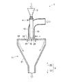
図1は、本実施形態の加熱処理工程で用いられる熱風処理装置1の構成を示す断面図である。図1では、熱風処理槽11および熱風噴射ノズル12の断面構成を示し、原料噴射ノズル13およびホッパ部17については、図面が錯綜して理解が困難になるので、正面図を示す。図2は、図1に示す熱風処理装置1の熱風噴射ノズル12および原料噴射ノズル13を拡大して示す断面図である。
FIG. 1 is a cross-sectional view showing a configuration of a hot
熱風処理装置1は、熱風処理槽11と、熱風噴射ノズル12と、原料噴射ノズル13と、断熱機構14と、衝突部材15と、エア噴射手段16とを含んで構成される。
The hot
図1に示すように、熱風処理槽11は、略円筒状の処理槽本体21と、処理槽本体21の上部の開口を塞ぐ天板22とを含む。処理槽本体21は、その軸線方向が鉛直方向に一致するように配置される。鉛直方向をZ1方向と定義し、このZ1方向の反対方向をZ2方向と定義し、Z1方向とZ2方向とを含んでZ方向と定義する。処理槽本体21は、上部の開口径が下部の開口径よりも大きく、軸線方向における上部と下部との間の中間部が、下部に近づくに従って開口径が小径となるテーパ状に形成されている。
As shown in FIG. 1, the hot
天板22は、処理槽本体21の上部に設けられている。処理槽本体21と天板22とによって形成される熱風処理槽11の内部空間には、混合工程で得られる原料混合物および熱風が熱風処理槽11の上部から供給される。天板22は、略円板状に形成されており、その中央部の第1取入口部23には第1エア取入口が形成され、外周部の第2取入口部24には第2エア取入口が形成されている。この第1エア取入口および第2エア取入口を通して、冷却用エアが取入れられる。
The
熱風噴射ノズル12は、熱風処理槽11の上方に設けられている。熱風噴射ノズル12は、L字形状に屈曲して形成されており、その一端部である熱風出口が形成される下端開口部25の開口端面が、天板22の上面を含む仮想平面に含まれるように、より詳細には下端開口部25の開口端面および天板22の上面のZ方向における位置が一致するように配置されている。熱風噴射ノズル12の熱風出口および天板22の第1エア取入口は円形状に形成されており、熱風噴射ノズル12は、熱風出口の軸線が、第1エア取入口の軸線と一致するように配置されている。この下端開口部25に形成される熱風出口から熱風処理槽11内に熱風が噴射される。
The hot
図2に示すように、原料噴射ノズル13は、原料出口が形成される下端開口部26が、熱風噴射ノズル12の下端開口部25の内方側に位置するように設けられている。また原料噴射ノズル13の下端開口部26は、熱風噴射ノズル12の下端開口部25よりも上方、すなわちZ2方向側に位置するように設けられている。
As shown in FIG. 2, the raw
原料噴射ノズル13の上部は、熱風噴射ノズル12の屈曲部40を貫通しており、外部に臨む上部には、原料混合物を貯溜するホッパ部17が設けられている。ホッパ部17の下部にはディフューザ27が設けられており、ホッパ部17内にはディフューザ27に向けて圧縮エアを噴射するエア噴射ノズル28が設けられている。エア噴射ノズル28からディフューザ27に圧縮エアを噴射すると、ホッパ部17内に貯溜された原料混合物が原料噴射ノズル13内へ吸引されて圧縮エアと混合され、その固気混合流体が原料噴射ノズル13の下端開口部26の原料出口から、熱風噴射ノズル12から噴射される熱風の中心部に向けて噴射される。
The upper part of the raw
衝突部材15は、原料噴射ノズル13の下方、より詳細には原料噴射ノズル13の下端開口部26の下方に、原料噴射ノズル13から離隔して設けられている。衝突部材15を設けることによって、原料噴射ノズル13から噴射される原料混合物を衝突によって分散させることができる。衝突部材15は、円板状または円錐状に形成されている。
The
断熱機構14は、原料噴射ノズル13の外側に設けられている。断熱機構14を設けることによって、原料噴射ノズル13と熱風噴射ノズル12とを断熱し、熱風噴射ノズル12内を流動する熱風との接触によって原料噴射ノズル13がトナー粒子の融点以上に昇温することを防止することができる。これによって、トナー粒子が溶融して原料噴射ノズル13の内面に付着して堆積することを防止することができる。
The
断熱機構14は、原料噴射ノズル13から離隔して原料噴射ノズル13を囲繞するように設けられる冷却ジャケット29を含む。断熱機構14は、原料噴射ノズル13の外側に設けられた内筒部14aと、内筒部14aの外側に設けられた外筒部14bとを含み、この内筒部14aと外筒部14bとによって冷却ジャケット29が形成されている。内筒部14aと外筒部14bとの間隙である冷却ジャケット29の流路には冷媒が流下する。冷却ジャケット29の下部には冷媒入口30が形成され、上部には冷媒出口31が形成されており、冷媒入口30から冷却ジャケット29内に冷媒を供給して原料噴射ノズル13を冷却し、冷却後の冷媒を冷媒出口31から流出させるようにしている。冷媒としては、−15℃のエチレングリコール50%水溶液が用いられる。冷媒は、これに限定されず、水または空気を冷媒として用いるようにしてもよい。
The
断熱機構14の内筒部14aの内周面部と原料噴射ノズル13の外周面部との間にはエア噴射通路32が形成されている。エア噴射通路32は、冷却ジャケット29の内表面部である内筒部14aの内周面部と、原料噴射ノズル13の外表面部である外周面部とによって形成されている。エア噴射通路32の上部にはエア入口33が形成されており、そのエア入口33からエア噴射通路32内に分散用エアである気体が供給される。エア噴射通路32内に供給された分散用エアは、エア噴射通路32内を下向き、すなわちZ1方向に流下して、下端の開口34から、衝突部材15の上面部である原料噴射ノズル13の下端開口部26を臨む表面部に向けて噴射される。
An
熱風処理装置1は、熱風噴射ノズル12から熱風処理槽11内に熱風を噴射すると共に、エア噴射通路32から衝突部材15に分散用エアを噴射し、かつ冷却ジャケット29内に冷媒を流動させる冷却状態において、原料噴射ノズル13から原料混合物と圧縮エアとの固気混合流体を噴射する。
The hot
原料噴射ノズル13から原料混合物が噴射されると、噴射された原料混合物は衝突部材15に衝突する。その衝突およびエア噴射通路32から衝突部材15の上面部に向けて噴射される分散用エアとによって、原料混合物である混合粒子が熱風中に分散される。これによって原料混合物を熱風と効果的に接触させることができるので、加熱処理を効率的に行なうことができる。また熱風噴射ノズル12から噴射される熱風は、その中心部分、すなわち熱風出口の中心部分において、他の部分に比べて高温になっている。本実施形態では、熱風出口の軸線と原料出口の軸線とが一致しており、原料混合物は、高温になっている熱風の中心部分に噴射されるので、熱風と効果的に接触することができ、その接触によってトナー粒子の表面が溶融し、加熱処理される。
When the raw material mixture is injected from the raw
本実施形態では、天板22に第1および第2エア取入口23,24が形成されており、この第1エア取入口23および第2エア取入口24から熱風処理槽11内に冷却用エアが流入するので、この冷却用エアによって、加熱処理された原料混合物を素速く冷却することができる。また第2エア取入口24から流入する冷却用エアによって熱風処理槽11の内面が冷却されるので、加熱処理された原料混合物は、熱風処理槽11の内面に付着することなく、熱風処理槽11の下部に形成される出口から排出される。
In the present embodiment, first and second air intakes 23 and 24 are formed in the
本実施形態では、原料噴射ノズル13の下端開口部26の開口端面は、熱風噴射ノズル12の下端開口部25の開口端面よりも上方に位置するように設けられる。すなわち原料噴射ノズル13の下端開口部26は、熱風噴射ノズル12の下端開口部25よりも、寸法Hだけ上方に位置するように設けられる。これによって、原料噴射ノズル13から噴射される原料混合物は熱風と直ちに接触することができ、また原料混合物が熱風の高温域で流動する時間を長くとることができるので、原料混合物をより効果的に加熱処理することができる。
In the present embodiment, the opening end face of the
図1および図2に示す熱風処理装置1としては、たとえば特開2004−276016号公報に開示されている球形化処理装置を用いることができ、具体的には、日本ニューマチック工業株式会社から表面改質機として市販されているメテオレインボー(商品名)などが挙げられる。特開2004−176016号公報に開示されている球形化処理装置では、反応槽が熱風処理槽に相当する。
As the hot
加熱処理工程では、混合工程で得られた原料混合物を、図1および図2に示す熱風処理装置1を用いて、熱風噴射ノズル12から熱風処理槽11内に供給される熱風の温度Ta[℃]および風量La[lt/min、0℃、1気圧]、原料噴射ノズル13から熱風処理槽11内に供給される原料混合物の供給速度Wf[g/min]、ならびに第1トナー粒子の2分の1(1/2)降下温度Tm[℃]が、下記式(1)および(2)を満足する条件下で、原料混合物を加熱処理する。
Tm<Ta×La/(La+Wf×1.4[lt/g])<Tm×3 …(1)
0.08[g/lt]×La<Wf<0.5[g/lt]×La …(2)
In the heat treatment step, the raw material mixture obtained in the mixing step is heated to a temperature Ta [° C.] of hot air supplied from the hot
Tm <Ta × La / (La + Wf × 1.4 [lt / g]) <Tm × 3 (1)
0.08 [g / lt] × La <Wf <0.5 [g / lt] × La (2)
熱風の風量Laは、0℃、1気圧の標準状態における値に換算した値であり、0℃、1気圧の標準状態において熱風処理槽11に対して1分間(min)当りに供給される熱風の体積(リットル;lt)で表される。
The hot air flow rate La is a value converted into a value in a standard state of 0 ° C. and 1 atmosphere, and hot air supplied to the hot
加熱処理工程では、熱風と原料混合物とが混合されるので、熱風中における第1トナー粒子の表面温度Tt[℃]は、熱風の温度Taおよび風量La、熱風中の第1トナー粒子の量、ならびに第1トナー粒子の比熱から、熱風中において第1トナー粒子に与えられる熱量を計算することによって求めることができる。具体的には、熱風中における第1トナー粒子の表面温度Tt[℃]は、熱風温度Ta、熱風風量Laおよび原料供給速度Wfと相関しており、式(1)の中辺「Ta×La/(La+Wf×1.4[lt/g])」で表すことができる。 In the heat treatment step, since the hot air and the raw material mixture are mixed, the surface temperature Tt [° C.] of the first toner particles in the hot air is the hot air temperature Ta and the air volume La, the amount of the first toner particles in the hot air, In addition, the amount of heat given to the first toner particles in the hot air can be calculated from the specific heat of the first toner particles. Specifically, the surface temperature Tt [° C.] of the first toner particles in the hot air correlates with the hot air temperature Ta, the hot air flow rate La, and the raw material supply speed Wf, and the middle side of the formula (1) “Ta × La /(La+Wf×1.4 [lt / g]) ”.
式(1)の中辺の値が第1トナー粒子の1/2降下温度Tm以下である、すなわちTa×La/(La+Wf×1.4)≦Tmであると、第1トナー粒子の表面温度Ttが低過ぎて第1トナー粒子の表面が充分に溶融されず、成形されにくいので、加熱処理によるトナーの流動性の向上が得られないか、または効果が得られても小さいものとなる。 When the value of the middle side of the formula (1) is equal to or lower than the ½ drop temperature Tm of the first toner particles, that is, Ta × La / (La + Wf × 1.4) ≦ Tm, the surface temperature of the first toner particles Since Tt is too low, the surface of the first toner particles is not sufficiently melted and is difficult to be molded, so that improvement in toner fluidity by heat treatment cannot be obtained, or even if an effect is obtained, it becomes small.
式(1)の中辺の値が第1トナー粒子の1/2降下温度Tmの3倍以上である、すなわちTa×La/(La+Wf×1.4)≧Tm×3であると、第1トナー粒子の表面温度Ttが高過ぎて第1トナー粒子の表面が過度に溶融し、第1トナー粒子同士が融着しやすくなり、またシリカ微粒子が第1トナー粒子表面に固着して流動性が低下する。 If the value of the middle side of the formula (1) is at least three times the ½ drop temperature Tm of the first toner particles, that is, Ta × La / (La + Wf × 1.4) ≧ Tm × 3, Since the surface temperature Tt of the toner particles is too high, the surfaces of the first toner particles are excessively melted, the first toner particles are easily fused to each other, and the silica fine particles are fixed to the surface of the first toner particles and have fluidity. descend.
式(1)を満足する、すなわちTm[℃]<Ta[℃]×La[lt/min]/(La[lt/min]+Wf[g/min]×1.4[lt/g])<Tm[℃]×3という条件下で加熱処理を行なうことによって、第1トナー粒子の表面温度Ttを好適な範囲にすることができるので、第1トナー粒子同士の融着および流動化剤であるシリカ微粒子の第1トナー粒子表面への固着を抑え、流動性をより確実に向上させることができる。 Formula (1) is satisfied, that is, Tm [° C.] <Ta [° C.] × La [lt / min] / (La [lt / min] + Wf [g / min] × 1.4 [lt / g]) < By performing the heat treatment under the condition of Tm [° C.] × 3, the surface temperature Tt of the first toner particles can be brought into a suitable range, and therefore, the first toner particles are fused and fluidized. The silica fine particles can be prevented from sticking to the surface of the first toner particles, and the fluidity can be improved more reliably.
図3は、熱風風量Laと原料供給速度Wfとの相関関係を示すグラフである。図3において横軸は、熱風風量La[lt/min、0℃、1気圧]を示し、縦軸は原料供給速度Wf[g/min]を示す。式(1)を満足する条件下において、熱風風量Laおよび原料供給速度Wfを変化させて加熱処理を行ない、加熱処理後の流動性を評価すると、電子写真用トナーとして必要な流動性を有する電子写真用トナーが得られる範囲は、参照符51で示される直線(以下「第1直線」という)と、参照符52で示される直線(以下「第2直線」という)との間の領域、すなわち図3において左下がりの斜線で示される領域Aおよび右下がりの斜線で示される領域Bであることが判った。第1直線51は、Wf=0.08[g/lt]×Laの直線を表し、第2直線は、Wf=0.5[g/lt]×Laの直線を表す。したがって式(2)を満足する、すなわち0.08[g/lt]×La<Wf<0.5[g/lt]×Laの条件下で加熱処理することによって、電子写真用トナーとして必要な流動性を有する第2トナー粒子を得ることができる。
FIG. 3 is a graph showing the correlation between the hot air flow rate La and the raw material supply speed Wf. In FIG. 3, the horizontal axis represents the hot air flow rate La [lt / min, 0 ° C., 1 atm], and the vertical axis represents the raw material supply speed Wf [g / min]. When the heat treatment is performed by changing the hot air flow rate La and the raw material supply speed Wf under the conditions satisfying the formula (1) and the fluidity after the heat treatment is evaluated, the electrons having the fluidity necessary as an electrophotographic toner are obtained. The range in which the photographic toner is obtained is an area between a straight line indicated by reference numeral 51 (hereinafter referred to as “first straight line”) and a straight line indicated by reference numeral 52 (hereinafter referred to as “second straight line”), that is, In FIG. 3, it was found that the region A is indicated by a slanting line with a lower left side and the region B is indicated by a slanting line with a lower right side. The first
式(2)は熱風中の原料混合物の濃度に関係しており、熱風中における第1トナー粒子の濃度は、式(2)の中辺である原料供給速度Wfおよび熱風風量Laと相関している。原料供給速度Wfが0.08La以下であると、流動性は良好となるが、熱風中における原料混合物の濃度が低くなり過ぎ、単位時間あたりに加熱処理することのできる原料混合物の量が過度に少なくなるので、生産性が低くなる。原料供給速度Wfが0.5La以上であると、熱風中における第1トナー粒子の濃度が高くなり過ぎ、第1トナー粒子を均一に加熱処理することが困難になり、またトナー粒子同士の融着が発生する。 Equation (2) relates to the concentration of the raw material mixture in the hot air, and the concentration of the first toner particles in the hot air correlates with the raw material supply speed Wf and the hot air flow rate La, which are the middle sides of the equation (2). Yes. When the raw material supply speed Wf is 0.08 La or less, the fluidity is good, but the concentration of the raw material mixture in the hot air is too low, and the amount of the raw material mixture that can be heat-treated per unit time is excessive. Because it decreases, productivity decreases. When the raw material supply speed Wf is 0.5 La or more, the concentration of the first toner particles in the hot air becomes too high, and it becomes difficult to uniformly heat the first toner particles, and the toner particles are fused to each other. Will occur.
式(2)を満足する、すなわち0.08[g/lt]×La[lt/min]<Wf[g/min]<0.5[g/lt]×La[lt/min]という条件下で加熱処理を行なうことによって、熱風中における第1トナー粒子の濃度を好適な範囲にすることができるので、第1トナー粒子をより均一に加熱処理し、均質なトナーを得ることができ、またトナー粒子同士の融着を抑え、流動性をより確実に向上させることができる。また生産性が過度に低くなることを防ぐことができる。
The condition (2) is satisfied, that is, the condition of 0.08 [g / lt] × La [lt / min] <Wf [g / min] <0.5 [g / lt] × La [lt / min] Since the concentration of the first toner particles in the hot air can be adjusted to a suitable range by performing the heat treatment in
[トナー粒子混合工程]
本工程では、粒子生成工程において得られた第1トナー粒子と、加熱処理工程において得られた第2トナー粒子とを含むトナー混合物を生成する。本実施形態では、第1トナー粒子と第2トナー粒子とを混合して、第1トナー粒子と第2トナー粒子とから成るトナー混合物を生成する。
[Toner particle mixing process]
In this step, a toner mixture containing the first toner particles obtained in the particle production step and the second toner particles obtained in the heat treatment step is produced. In this embodiment, the first toner particles and the second toner particles are mixed to generate a toner mixture composed of the first toner particles and the second toner particles.
第1トナー粒子は、第2トナー粒子100質量部に対して、10質量部以上40質量部以下の質量比の範囲内で使用される。 The first toner particles are used within a mass ratio range of 10 parts by weight to 40 parts by weight with respect to 100 parts by weight of the second toner particles.
具体的には、加熱処理工程で得られた第2トナー粒子の100質量部に対して、前述の粒子生成工程において得られた第1トナー粒子を10質量部以上40質量部以下添加し、混合装置で可及的に均一に混合し、トナー混合物を生成する。第1トナー粒子と第2トナー粒子との混合に用いられる混合装置としては、ヘンシェルミキサ、スーパーミキサなどが挙げられる。混合装置は、これらに限定されるものではなく、粉体を混合できる装置であれば、どれでも混合装置として用いることができる。 Specifically, 10 parts by mass or more and 40 parts by mass or less of the first toner particles obtained in the above-described particle generation process are added to 100 parts by mass of the second toner particles obtained in the heat treatment process, and mixed. Mix as uniformly as possible in the device to produce a toner mixture. Examples of the mixing device used for mixing the first toner particles and the second toner particles include a Henschel mixer and a super mixer. The mixing apparatus is not limited to these, and any apparatus capable of mixing powder can be used as the mixing apparatus.
このようにトナー粒子混合工程で得られるトナー混合物は、そのまま非磁性一成分現像用トナーとして用いられる。 Thus, the toner mixture obtained in the toner particle mixing step is used as it is as a non-magnetic one-component developing toner.
なお、上記では、予め流動化剤を混合した原料混合物を加熱処理工程で加熱処理したが、第1トナー粒子を加熱処理工程で加熱処理し、得られたトナー粒子を第2トナー粒子として第1トナー粒子および流動化剤、フィルミング防止剤などの外添剤とともに混合して非磁性一成分現像用トナーとしてもよい。 In the above, the raw material mixture in which the fluidizing agent is mixed in advance is heat-treated in the heat treatment step. However, the first toner particles are heat-treated in the heat treatment step, and the obtained toner particles are used as the second toner particles as the first toner particles. The toner may be mixed with an external additive such as a toner particle, a fluidizing agent, and an anti-filming agent to form a nonmagnetic one-component developing toner.
以上のようにして得られた非磁性一成分現像用トナーは、流動性が良好であるとともに、帯電ブレードおよび現像ローラーを汚染せずに画像の濃度ムラや帯電不良によるかぶりを防止する。 The non-magnetic one-component developing toner obtained as described above has good fluidity and prevents fog due to image density unevenness or charging failure without contaminating the charging blade and the developing roller.
<実施例>
以下に実施例を挙げて本発明を更に詳細に説明するが、本発明はこれらの実施例のみに限定されるものではない。なお、特に断りのない限り、「%」は「質量%」を意味し、「部」は「質量部」を意味する。
<Example>
The present invention will be described in more detail with reference to the following examples, but the present invention is not limited to these examples. Unless otherwise specified, “%” means “% by mass”, and “part” means “part by mass”.
(a)第1および第2トナー粒子の生成
(第1トナー粒子)
結着剤として市販の非磁性カラートナー用ポリエステル樹脂(商品名:HP−325、日本合成化学工業株式会社製)10質量部と、着色剤としてマゼンタ色着色剤(ピグメントレッド57:1)5質量部とを溶融混合した後、熱ロールで溶融混練し、得られた混練物を冷却して固化させ、粗粉砕してマスターバッチを得た。このマスターバッチ15質量部に、非磁性カラートナー用スチレンアクリル樹脂(商品名:SE−1035)40質量部と、非磁性トナー用ポリエステル樹脂(商品名:ET2900、エスケーケミカルズ(SK Chemicals)社製)80質量部と、荷電調整剤としてアルキルサリチル酸亜鉛(商品名:ボントロン(BONTRON)E−84、オリエント化学工業株式会社製)2質量部と、離型剤としてポリエチレン(商品名:サンワックス161−P、三洋化成工業株式会社製)4質量部とを加えて混合した後、二軸押出混練機を用いて混練して混練物を得た。この混練物を冷却して固化させた後、粉砕して分級を行い、マゼンタ色の第1トナー粒子を得た。得られた第1トナー粒子の1/2降下温度Tmは127℃であった。
(A) Generation of first and second toner particles (first toner particles)
10 parts by mass of a commercially available polyester resin for non-magnetic color toner (trade name: HP-325, manufactured by Nippon Synthetic Chemical Industry Co., Ltd.) as a binder and 5 parts by mass of a magenta colorant (Pigment Red 57: 1) as a colorant Then, the resulting kneaded product was cooled and solidified, and coarsely pulverized to obtain a master batch. 15 parts by mass of this master batch, 40 parts by mass of styrene acrylic resin for non-magnetic color toner (trade name: SE-1035) and polyester resin for non-magnetic toner (trade name: ET2900, manufactured by SK Chemicals) 80 parts by mass, 2 parts by mass of a zinc alkylsalicylate (trade name: Bontron E-84, manufactured by Orient Chemical Co., Ltd.) as a charge control agent, and polyethylene (trade name: Sunwax 161-P) as a release agent And 4 parts by mass of Sanyo Chemical Industries, Ltd.) were added and mixed, and then kneaded using a twin-screw extrusion kneader to obtain a kneaded product. The kneaded product was cooled and solidified, and then pulverized and classified to obtain magenta first toner particles. The resulting first toner particles had a ½ drop temperature Tm of 127 ° C.
(第2トナー粒子A)
前述の第1トナー粒子の100質量部に対して、BET比表面積が220m2/gであるシリカ微粒子(商品名:R812S、日本アエロジル株式会社製)3質量部を加え、ヘンシェルミキサを用いて混合し、原料混合物を得た。得られた原料混合物を、図1および図2に示す構成の熱風処理装置(商品名:メテオレインボーMR−10型、日本ニューマチック工業株式会社製)を用いて、表1に示すように熱風温度Taを380℃とし、熱風風量Laを600[lt/min、0℃、1気圧]とし、原料供給速度Wfを167[g/min]として加熱処理し、第2トナー粒子Aを得た。
(Second toner particles A)
3 parts by mass of silica fine particles (trade name: R812S, manufactured by Nippon Aerosil Co., Ltd.) having a BET specific surface area of 220 m 2 / g are added to 100 parts by mass of the first toner particles described above and mixed using a Henschel mixer. Thus, a raw material mixture was obtained. As shown in Table 1, the obtained raw material mixture was heated as shown in Table 1 using a hot air treatment apparatus (trade name: Meteole Inbo MR-10 type, manufactured by Nippon Pneumatic Industry Co., Ltd.) having the configuration shown in FIGS. Heat treatment was performed at Ta of 380 ° C., hot air flow rate La of 600 [lt / min, 0 ° C., 1 atm], and raw material supply rate Wf of 167 [g / min], whereby second toner particles A were obtained.
(第2トナー粒子B)
前述の第1トナー粒子の100質量部に対して、BET比表面積が220m2/gであるシリカ微粒子(商品名:R812S、日本アエロジル株式会社製)3質量部を加え、ヘンシェルミキサを用いて混合し、原料混合物を得た。得られた原料混合物を、図1および図2に示す構成の熱風処理装置(商品名:メテオレインボーMR−10型、日本ニューマチック工業株式会社製)を用いて、表1に示すように熱風温度Taを340℃とし、熱風風量Laを600[lt/min、0℃、1気圧]とし、原料供給速度Wfを167[g/min]として加熱処理し、第2トナー粒子Bを得た。
(Second toner particles B)
3 parts by mass of silica fine particles (trade name: R812S, manufactured by Nippon Aerosil Co., Ltd.) having a BET specific surface area of 220 m 2 / g are added to 100 parts by mass of the first toner particles described above and mixed using a Henschel mixer. Thus, a raw material mixture was obtained. As shown in Table 1, the obtained raw material mixture was heated as shown in Table 1 using a hot air treatment apparatus (trade name: Meteole Inbo MR-10 type, manufactured by Nippon Pneumatic Industry Co., Ltd.) having the configuration shown in FIGS. Heat treatment was performed at Ta of 340 ° C., hot air flow rate La of 600 [lt / min, 0 ° C., 1 atm], and raw material supply rate Wf of 167 [g / min], whereby second toner particles B were obtained.
(第2トナー粒子C)
前述の第1トナー粒子の100質量部に対して、BET比表面積が220m2/gであるシリカ微粒子(商品名:R812S、日本アエロジル株式会社製)3質量部を加え、ヘンシェルミキサを用いて混合し、原料混合物を得た。得られた原料混合物を、図1および図2に示す構成の熱風処理装置(商品名:メテオレインボーMR−10型、日本ニューマチック工業株式会社製)を用いて、表1に示すように熱風温度Taを292℃とし、熱風風量Laを600[lt/min、0℃、1気圧]とし、原料供給速度Wfを167[g/min]として加熱処理し、第2トナー粒子Cを得た。
(Second toner particles C)
3 parts by mass of silica fine particles (trade name: R812S, manufactured by Nippon Aerosil Co., Ltd.) having a BET specific surface area of 220 m 2 / g are added to 100 parts by mass of the first toner particles described above and mixed using a Henschel mixer. Thus, a raw material mixture was obtained. As shown in Table 1, the obtained raw material mixture was heated as shown in Table 1 using a hot air treatment apparatus (trade name: Meteole Inbo MR-10 type, manufactured by Nippon Pneumatic Industry Co., Ltd.) having the configuration shown in FIGS. Heat treatment was performed at Ta of 292 ° C., hot air flow rate La of 600 [lt / min, 0 ° C., 1 atm], and raw material supply rate Wf of 167 [g / min], whereby second toner particles C were obtained.
(b)非磁性一成分現像用トナーの製造
(実施例1)
第2トナー粒子A100質量部に対して、シリカ微粒子(商品名:R812S、日本アエロジル株式会社製)1質量部と第1トナー粒子25質量部を加え、ヘンシェルミキサを用いて混合し、実施例1の非磁性一成分現像用トナーを得た。
(B) Production of toner for non-magnetic one-component development (Example 1)
Example 1 1 part by weight of silica fine particles (trade name: R812S, manufactured by Nippon Aerosil Co., Ltd.) and 25 parts by weight of first toner particles are added to 100 parts by weight of the second toner particles A and mixed using a Henschel mixer. A non-magnetic one-component developing toner was obtained.
(実施例2)
第1トナー粒子の添加量を10質量部に変更した以外は実施例1と同様にして、実施例2の非磁性一成分現像用トナーを得た。
(Example 2)
A nonmagnetic one-component developing toner of Example 2 was obtained in the same manner as in Example 1 except that the addition amount of the first toner particles was changed to 10 parts by mass.
(実施例3)
第1トナー粒子の添加量を40質量部に変更した以外は実施例1と同様にして、実施例3の非磁性一成分現像用トナーを得た。
(Example 3)
A nonmagnetic one-component developing toner of Example 3 was obtained in the same manner as in Example 1 except that the addition amount of the first toner particles was changed to 40 parts by mass.
(比較例1)
第1トナー粒子の添加量を50質量部に変更した以外は実施例1と同様にして、比較例1の非磁性一成分現像用トナーを得た。
(Comparative Example 1)
A nonmagnetic one-component developing toner of Comparative Example 1 was obtained in the same manner as in Example 1 except that the addition amount of the first toner particles was changed to 50 parts by mass.
(比較例2)
第1トナー粒子の添加量を75質量部に変更した以外は実施例1と同様にして、比較例2の非磁性一成分現像用トナーを得た。
(Comparative Example 2)
A nonmagnetic one-component developing toner of Comparative Example 2 was obtained in the same manner as in Example 1 except that the addition amount of the first toner particles was changed to 75 parts by mass.
(比較例3)
第1トナー粒子の添加量を100質量部に変更した以外は実施例1と同様にして、比較例3の非磁性一成分現像用トナーを得た。
(Comparative Example 3)
A nonmagnetic one-component developing toner of Comparative Example 3 was obtained in the same manner as in Example 1 except that the addition amount of the first toner particles was changed to 100 parts by mass.
(比較例4)
第1トナー粒子を添加しなかったこと以外は実施例1と同様にして、比較例4の非磁性一成分現像用トナーを得た。
(Comparative Example 4)
A nonmagnetic one-component developing toner of Comparative Example 4 was obtained in the same manner as in Example 1 except that the first toner particles were not added.
(比較例5)
第2トナー粒子Aを第2トナー粒子Bに変更したことと、第1トナー粒子を添加しなかったこと以外は実施例1と同様にして、比較例5の非磁性一成分現像用トナーを得た。
(Comparative Example 5)
A nonmagnetic one-component developing toner of Comparative Example 5 was obtained in the same manner as in Example 1 except that the second toner particles A were changed to the second toner particles B and the first toner particles were not added. It was.
(比較例6)
第2トナー粒子Aを第2トナー粒子Cに変更したことと、第1トナー粒子を添加しなかったこと以外は実施例1と同様にして、比較例6の非磁性一成分現像用トナーを得た。
(Comparative Example 6)
A nonmagnetic one-component developing toner of Comparative Example 6 was obtained in the same manner as in Example 1 except that the second toner particles A were changed to the second toner particles C and that the first toner particles were not added. It was.
<評価結果>
以上のようにして得られた実施例1〜3および比較例1〜6の非磁性一成分現像用トナーについて、以下のようにして評価を行った。評価結果を表1に示す。
<Evaluation results>
The nonmagnetic one-component developing toners of Examples 1 to 3 and Comparative Examples 1 to 6 obtained as described above were evaluated as follows. The evaluation results are shown in Table 1.
(トルク値)
容量100ccのステンレス製カップに、非磁性一成分現像用トナーを充填率が52%となるように充填し、これに平板状の羽根を挿入して200rpmで回転させた時のトルク値(mN・m)を測定した。トルク値が小さいほど非磁性一成分現像用トナーの流動性は高い。
(Torque value)
A non-magnetic one-component developing toner is filled in a 100 cc stainless steel cup so as to have a filling rate of 52%, a flat blade is inserted into this, and a torque value (mN · m) was measured. The smaller the torque value, the higher the fluidity of the non-magnetic one-component developing toner.
(ジッタ)
全面べた画像を3枚連続で印刷し、得られた画像を目視観察して、画像への縞状の濃淡の発生の有無および発生の程度を確認し、その結果からジッタの程度を判断し、以下の基準に基づいて評価した。
○:良好。縞状の濃淡が発生しておらず、ジッタなし。
×:不良。縞状の濃淡が著しく発生しており、ジッタが顕著である。
(Jitter)
Three continuous images are printed continuously, and the obtained image is visually observed to confirm the presence or absence of stripe-like shading on the image and the extent of the occurrence. From the results, the degree of jitter is determined, Evaluation was based on the following criteria.
○: Good. There are no stripes and no jitter.
X: Defect. Striped shading is remarkably generated and jitter is remarkable.
(帯電ブレード固着)
1000枚印刷時(1000p)および4500枚印刷時(4500p)の全面ハーフトーン画像を目視観察して、画像への縦筋の発生の有無および発生の程度を確認、および実際に帯電ブレードを目視で確認し、帯電ブレードへのトナー固着の発生の程度を確認し、その結果から帯電ブレード固着の程度を判断し、以下の基準に基づいて評価した。なお、比較例4および5については1000pの段階でブレード固着が不良だったため、その後の4500pでの評価は行わず、表1には「−」と記載した。
○:良好。画像に縦状の筋が発生しておらず、かつ帯電ブレードにも固着物がない。
×:不良。画像に縦状の筋が著しく発生しており、かつ帯電ブレードにも固着物が多数ある。
(Charging blade fixed)
Visually observe the entire halftone image when printing 1000 sheets (1000p) and when printing 4500 sheets (4500p) to confirm the presence and extent of vertical stripes on the image, and visually check the charging blade. The degree of toner adhesion to the charging blade was confirmed, the degree of charging blade adhesion was judged from the result, and the evaluation was made based on the following criteria. In Comparative Examples 4 and 5, since blade fixation was poor at the stage of 1000 p, the subsequent evaluation at 4500 p was not performed, and “-” is shown in Table 1.
○: Good. There are no vertical streaks in the image, and the charging blade has no sticking matter.
X: Defect. The vertical streaks are remarkably generated in the image, and there are many fixed objects on the charging blade.

1 熱風処理装置
11 熱風処理槽
12 熱風噴射ノズル
13 原料噴射ノズル
14 断熱機構
15 衝突部材
16 エア噴射手段
17 ホッパ部
DESCRIPTION OF
Claims (2)
熱処理槽、熱処理槽の内部空間に向けて熱風を噴射する熱風噴射ノズル、および熱風噴射ノズルから噴射される熱風に向けて原料を噴射する原料噴射ノズルを備えた熱処理装置を用いて、前記第1トナー粒子を前記原料として熱処理して得られた第2トナー粒子100質量部と、
流動化剤とを混合してなることを特徴とする非磁性一成分現像用トナー。 10 to 40 parts by mass of first toner particles obtained by a pulverization method, containing at least a binder, a colorant, a release agent, and a charge control agent;
The heat treatment tank includes a heat treatment apparatus including a heat treatment tank, a hot air injection nozzle that injects hot air toward the internal space of the heat treatment tank, and a raw material injection nozzle that injects a raw material toward the hot air injected from the hot air injection nozzle. 100 parts by mass of second toner particles obtained by heat treatment using toner particles as the raw material;
A non-magnetic one-component developing toner comprising a fluidizing agent.
上部に冷却用エアを取入れるためのエア取入口が形成され、上部から内部空間に前記第2トナー粒子および熱風が供給される熱風処理槽と、熱風処理槽の上部から内部空間に向けて熱風を噴射する熱風噴射ノズルと、熱風噴射ノズルから噴射される熱風に向けて原料を噴射する原料噴射ノズルであって、原料が噴射される原料出口が形成される下端開口部が、熱風噴射ノズルの熱風が噴射される熱風出口が形成される下端開口部の内方側に、熱風噴射ノズルの下端開口部よりも上方に位置するように設けられる原料噴射ノズルと、原料噴射ノズルから離隔して原料噴射ノズルを囲繞するように設けられ、内部に冷媒が流下する流路が形成される冷却ジャケットを含み、原料噴射ノズルと熱風噴射ノズルとを断熱する断熱機構と、原料噴射ノズルの下端開口部の下方に原料噴射ノズルから離隔して設けられる衝突部材と、原料噴射ノズルの外表面部と断熱機構の冷却ジャケットの内表面部とによって形成されるエア噴射流路の下端の開口から、衝突部材の原料噴射ノズルの下端開口部を臨む表面部に向けて分散用エアを噴射するエア噴射手段と、を備える熱風処理装置を用いて、
熱風噴射ノズルから熱風処理槽内に供給される熱風の温度Ta[℃]および風量La[lt/min、0℃、1気圧]、原料噴射ノズルから熱風処理槽内に供給される原料混合物の供給速度Wf[g/min]、ならびにトナー粒子の2分の1(1/2)降下温度Tm[℃]が、下記式(1)および(2)を満足する条件下で、加熱処理されることを特徴とする請求項1記載の非磁性一成分現像用トナー。
Tm<Ta×La/(La+Wf×1.4[lt/g])<Tm×3 …(1)
0.08[g/lt]×La<Wf<0.5[g/lt]×La …(2) The second toner particles are
An air inlet for taking in cooling air is formed in the upper part, and a hot air treatment tank in which the second toner particles and hot air are supplied from the upper part to the internal space, and hot air from the upper part of the hot air treatment tank toward the internal space A hot air injection nozzle for injecting a raw material and a raw material injection nozzle for injecting a raw material toward the hot air injected from the hot air injection nozzle, wherein a lower end opening in which a raw material outlet through which the raw material is injected is formed is A raw material injection nozzle provided so as to be located above the lower end opening of the hot air injection nozzle on the inner side of the lower end opening where the hot air outlet from which hot air is injected is formed, and the raw material is separated from the raw material injection nozzle A heat insulation mechanism that includes a cooling jacket that is provided so as to surround the injection nozzle and in which a flow path through which a refrigerant flows is formed, and that insulates the raw material injection nozzle from the hot air injection nozzle; and a raw material injection nozzle The lower end opening of the air injection flow path formed by the collision member provided below the lower end opening of the material and spaced from the raw material injection nozzle, the outer surface portion of the raw material injection nozzle, and the inner surface portion of the cooling jacket of the heat insulation mechanism From the hot air treatment device comprising, air injection means for injecting the dispersion air toward the surface portion facing the lower end opening of the raw material injection nozzle of the collision member,
Supply of the raw material mixture supplied from the raw material injection nozzle into the hot air treatment tank, temperature Ta [° C.] and air volume La [lt / min, 0 ° C., 1 atm] supplied from the hot air injection nozzle into the hot air treatment tank Heat treatment is performed under conditions where the speed Wf [g / min] and the half (1/2) temperature drop Tm [° C.] of the toner particles satisfy the following formulas (1) and (2). The non-magnetic one-component developing toner according to claim 1.
Tm <Ta × La / (La + Wf × 1.4 [lt / g]) <Tm × 3 (1)
0.08 [g / lt] × La <Wf <0.5 [g / lt] × La (2)
Priority Applications (1)
| Application Number | Priority Date | Filing Date | Title |
|---|---|---|---|
| JP2009098486A JP2010250024A (en) | 2009-04-14 | 2009-04-14 | Toner for nonmagnetic single component development |
Applications Claiming Priority (1)
| Application Number | Priority Date | Filing Date | Title |
|---|---|---|---|
| JP2009098486A JP2010250024A (en) | 2009-04-14 | 2009-04-14 | Toner for nonmagnetic single component development |
Publications (2)
| Publication Number | Publication Date |
|---|---|
| JP2010250024A true JP2010250024A (en) | 2010-11-04 |
| JP2010250024A5 JP2010250024A5 (en) | 2012-06-07 |
Family
ID=43312430
Family Applications (1)
| Application Number | Title | Priority Date | Filing Date |
|---|---|---|---|
| JP2009098486A Pending JP2010250024A (en) | 2009-04-14 | 2009-04-14 | Toner for nonmagnetic single component development |
Country Status (1)
| Country | Link |
|---|---|
| JP (1) | JP2010250024A (en) |
Citations (8)
| Publication number | Priority date | Publication date | Assignee | Title |
|---|---|---|---|---|
| JPH0749584A (en) * | 1993-08-05 | 1995-02-21 | Minolta Co Ltd | Developer for developing electrostatic latent image |
| JP2004138691A (en) * | 2002-10-16 | 2004-05-13 | Mitsubishi Chemicals Corp | Method for manufacturing toner for developing electrostatic latent image |
| JP2004276016A (en) * | 2003-02-24 | 2004-10-07 | Nippon Pneumatic Mfg Co Ltd | Spheriodizing treatment apparatus |
| JP2005189755A (en) * | 2003-12-26 | 2005-07-14 | Kyocera Mita Corp | Electrostatic image developing toner |
| JP2006293335A (en) * | 2005-03-16 | 2006-10-26 | Ricoh Co Ltd | Image forming apparatus, toner for image formation, and process cartridge |
| JP2008119645A (en) * | 2006-11-14 | 2008-05-29 | Sakata Corp | Method for manufacturing toner for electrophotography and toner for electrophotography |
| JP2009015035A (en) * | 2007-07-05 | 2009-01-22 | Canon Inc | Surface modification device for toner |
| JP2009075208A (en) * | 2007-09-19 | 2009-04-09 | Tomoegawa Paper Co Ltd | Method for producing toner for developing electrostatically charged image and toner for developing electrostatically charged image |
-
2009
- 2009-04-14 JP JP2009098486A patent/JP2010250024A/en active Pending
Patent Citations (8)
| Publication number | Priority date | Publication date | Assignee | Title |
|---|---|---|---|---|
| JPH0749584A (en) * | 1993-08-05 | 1995-02-21 | Minolta Co Ltd | Developer for developing electrostatic latent image |
| JP2004138691A (en) * | 2002-10-16 | 2004-05-13 | Mitsubishi Chemicals Corp | Method for manufacturing toner for developing electrostatic latent image |
| JP2004276016A (en) * | 2003-02-24 | 2004-10-07 | Nippon Pneumatic Mfg Co Ltd | Spheriodizing treatment apparatus |
| JP2005189755A (en) * | 2003-12-26 | 2005-07-14 | Kyocera Mita Corp | Electrostatic image developing toner |
| JP2006293335A (en) * | 2005-03-16 | 2006-10-26 | Ricoh Co Ltd | Image forming apparatus, toner for image formation, and process cartridge |
| JP2008119645A (en) * | 2006-11-14 | 2008-05-29 | Sakata Corp | Method for manufacturing toner for electrophotography and toner for electrophotography |
| JP2009015035A (en) * | 2007-07-05 | 2009-01-22 | Canon Inc | Surface modification device for toner |
| JP2009075208A (en) * | 2007-09-19 | 2009-04-09 | Tomoegawa Paper Co Ltd | Method for producing toner for developing electrostatically charged image and toner for developing electrostatically charged image |
Similar Documents
| Publication | Publication Date | Title |
|---|---|---|
| JP4918583B2 (en) | Toner manufacturing method and toner | |
| JP5078059B2 (en) | Method for producing toner for developing electrostatic image | |
| JP4136171B2 (en) | Toner for electrophotography, method for producing the same, and image forming method | |
| JP4283800B2 (en) | Toner for developing electrostatic image and method for producing the same | |
| JP4959300B2 (en) | Method for producing electrophotographic toner and electrophotographic toner | |
| JP5374171B2 (en) | Nonmagnetic one-component negatively chargeable toner manufacturing method and nonmagnetic one-component negatively chargeable toner | |
| JP2010277000A (en) | Capsule toner and method for producing the same | |
| JP2014224872A (en) | Capsule toner and manufacturing method of the same | |
| JP2010250024A (en) | Toner for nonmagnetic single component development | |
| JP4272081B2 (en) | Method for producing toner for electrophotography | |
| JP4967033B2 (en) | Capsule toner manufacturing method and capsule toner | |
| JP4488505B2 (en) | Toner production method | |
| JP2007296494A (en) | Method for classifying powder, method for manufacturing toner and powder classifier | |
| JP4322577B2 (en) | Powder kneading method and powder kneading apparatus | |
| JP2011059355A (en) | Method of producing toner | |
| JP5342215B2 (en) | Negatively chargeable toner and method for producing the same | |
| JP2011070035A (en) | Method for producing toner for single-component developer | |
| JP2008249990A (en) | Method for manufacturing toner for electrostatic charge image development | |
| JP2010256737A (en) | Method for producing toner, toner and two-component developer | |
| JP2005017849A (en) | Image forming method | |
| JP2022028069A (en) | Toner, toner storage unit, image forming apparatus, and image forming method | |
| JP3570041B2 (en) | Method for producing one-component toner | |
| JP5286176B2 (en) | Method for producing capsule toner | |
| JP5075502B2 (en) | Method for producing toner for developing electrostatic image | |
| JP2012173413A (en) | Capsule toner and manufacturing method thereof |
Legal Events
| Date | Code | Title | Description |
|---|---|---|---|
| A521 | Written amendment |
Free format text: JAPANESE INTERMEDIATE CODE: A523 Effective date: 20120412 |
|
| A621 | Written request for application examination |
Free format text: JAPANESE INTERMEDIATE CODE: A621 Effective date: 20120412 |
|
| A977 | Report on retrieval |
Free format text: JAPANESE INTERMEDIATE CODE: A971007 Effective date: 20130801 |
|
| A131 | Notification of reasons for refusal |
Free format text: JAPANESE INTERMEDIATE CODE: A131 Effective date: 20130910 |
|
| A02 | Decision of refusal |
Free format text: JAPANESE INTERMEDIATE CODE: A02 Effective date: 20140121 |