JP2010249604A - Optical measuring apparatus, optical measuring method, and optical measurement processing program - Google Patents
Optical measuring apparatus, optical measuring method, and optical measurement processing program Download PDFInfo
- Publication number
- JP2010249604A JP2010249604A JP2009098113A JP2009098113A JP2010249604A JP 2010249604 A JP2010249604 A JP 2010249604A JP 2009098113 A JP2009098113 A JP 2009098113A JP 2009098113 A JP2009098113 A JP 2009098113A JP 2010249604 A JP2010249604 A JP 2010249604A
- Authority
- JP
- Japan
- Prior art keywords
- measurement
- optical
- reception signal
- light reception
- scanning
- Prior art date
- Legal status (The legal status is an assumption and is not a legal conclusion. Google has not performed a legal analysis and makes no representation as to the accuracy of the status listed.)
- Withdrawn
Links
- 238000005259 measurement Methods 0.000 title claims abstract description 166
- 230000003287 optical effect Effects 0.000 title claims abstract description 59
- 238000000034 method Methods 0.000 title abstract description 6
- 238000012937 correction Methods 0.000 claims abstract description 23
- 238000010586 diagram Methods 0.000 description 8
- 239000011521 glass Substances 0.000 description 7
- 230000001681 protective effect Effects 0.000 description 5
- 238000000691 measurement method Methods 0.000 description 4
- 238000012545 processing Methods 0.000 description 4
- 230000005540 biological transmission Effects 0.000 description 3
- 230000000694 effects Effects 0.000 description 2
- 238000011161 development Methods 0.000 description 1
- 238000006073 displacement reaction Methods 0.000 description 1
- 239000004065 semiconductor Substances 0.000 description 1
Images


Classifications
-
- G—PHYSICS
- G01—MEASURING; TESTING
- G01B—MEASURING LENGTH, THICKNESS OR SIMILAR LINEAR DIMENSIONS; MEASURING ANGLES; MEASURING AREAS; MEASURING IRREGULARITIES OF SURFACES OR CONTOURS
- G01B11/00—Measuring arrangements characterised by the use of optical techniques
- G01B11/24—Measuring arrangements characterised by the use of optical techniques for measuring contours or curvatures
- G01B11/2433—Measuring arrangements characterised by the use of optical techniques for measuring contours or curvatures for measuring outlines by shadow casting
-
- G—PHYSICS
- G01—MEASURING; TESTING
- G01B—MEASURING LENGTH, THICKNESS OR SIMILAR LINEAR DIMENSIONS; MEASURING ANGLES; MEASURING AREAS; MEASURING IRREGULARITIES OF SURFACES OR CONTOURS
- G01B21/00—Measuring arrangements or details thereof, where the measuring technique is not covered by the other groups of this subclass, unspecified or not relevant
- G01B21/02—Measuring arrangements or details thereof, where the measuring technique is not covered by the other groups of this subclass, unspecified or not relevant for measuring length, width, or thickness
- G01B21/04—Measuring arrangements or details thereof, where the measuring technique is not covered by the other groups of this subclass, unspecified or not relevant for measuring length, width, or thickness by measuring coordinates of points
- G01B21/045—Correction of measurements
Abstract
Description
本発明は、測定対象物が配置される測定領域を通過した光を測定し、測定対象物の形状を測定する光学式測定装置、光学式測定方法、及び光学式測定処理プログラムに関する。 The present invention relates to an optical measurement apparatus, an optical measurement method, and an optical measurement processing program that measure light passing through a measurement region in which a measurement object is disposed and measure the shape of the measurement object.
光学式測定装置は、測定対象物が位置する測定領域を隔てて配置された送光部と受光部とを備える。送光部からの平行ビームにより測定領域を繰り返し走査し、測定領域を通過したビームを受光部で受光し、これにより発生した受光信号に所定の処理をして、測定値(測定対象物の寸法や真円度等)を表示する。 The optical measurement apparatus includes a light transmitting unit and a light receiving unit that are arranged with a measurement region where the measurement object is located. The measurement region is repeatedly scanned with the parallel beam from the light transmitting unit, the beam that has passed through the measurement region is received by the light receiving unit, and the light reception signal generated thereby is subjected to predetermined processing to obtain a measurement value (dimension of the measurement object). Or roundness).
このような光学式測定装置において、その縦方向(走査方向と平行な方向)の補正は、例えば、特許文献1記載の方法等を用いて実行される。また、各装置に固有の補正データは、特許文献2記載の装置を用いて実装される。
In such an optical measurement apparatus, correction in the vertical direction (direction parallel to the scanning direction) is performed using, for example, the method described in
しかしながら、光学式測定装置において、横方向(走査方向に直交する方向)の補正はなされておらず、その開発が望まれている。 However, the optical measurement apparatus is not corrected in the horizontal direction (direction orthogonal to the scanning direction), and its development is desired.
本発明は、横方向の補正を可能とした光学式測定装置、光学式測定方法、及び光学式測定処理プログラムを提供することを目的とする。 An object of the present invention is to provide an optical measurement apparatus, an optical measurement method, and an optical measurement processing program that enable lateral correction.
本発明にかかる光学式測定装置は、測定対象物が配置される測定領域にて焦点を結ぶビームを成形すると共に前記測定領域にて前記ビームを走査する送光部と、前記測定領域を通過したビームを受光し、当該受光したビームに基づく受光信号を出力する受光部と、前記受光信号に基づき前記測定対象物の寸法を示す測定値を算出する測定値算出部と、前記ビームを走査する単位時間に対する前記受光信号の強度の変化量に基づき、前記測定値を補正する補正部とを備えることを特徴とする。 An optical measurement apparatus according to the present invention forms a beam that is focused in a measurement region where a measurement object is disposed, and transmits a light transmission unit that scans the beam in the measurement region, and passes through the measurement region. A light receiving unit that receives a beam and outputs a light reception signal based on the received beam, a measurement value calculation unit that calculates a measurement value indicating the dimension of the measurement object based on the light reception signal, and a unit that scans the beam And a correction unit that corrects the measurement value based on a change amount of the intensity of the received light signal with respect to time.
本発明にかかる光学式測定方法は、測定対象物が配置される測定領域にて焦点を結ぶビームを成形すると共に前記測定領域にて前記ビームを走査するステップと、前記測定領域を通過したビームに基づく受光信号により前記測定対象物の寸法を示す測定値を算出するステップと、前記ビームを走査する単位時間に対する前記受光信号の強度の変化量に基づき、前記測定値を補正するステップとを備えることを特徴とする。 An optical measurement method according to the present invention includes a step of forming a focused beam in a measurement region where a measurement object is disposed and scanning the beam in the measurement region; and a beam passing through the measurement region. Calculating a measurement value indicating the dimension of the measurement object based on the received light signal, and correcting the measurement value based on a change amount of the intensity of the light reception signal with respect to a unit time for scanning the beam. It is characterized by.
本発明にかかる光学式測定処理プログラムはコンピュータに、測定対象物が配置される測定領域にて焦点を結ぶビームを成形すると共に前記測定領域にて前記ビームを走査するステップと、前記測定領域を通過したビームに基づく受光信号により前記測定対象物の寸法を示す測定値を算出するステップと、前記ビームを走査する単位時間に対する前記受光信号の強度の変化量に基づき、前記測定値を補正するステップとを実行させるためのものである。 An optical measurement processing program according to the present invention forms, on a computer, a beam focused at a measurement region where a measurement object is arranged, and scans the beam at the measurement region, and passes through the measurement region. Calculating a measurement value indicating a dimension of the measurement object based on a received light signal based on the beam, and correcting the measured value based on a change amount of the intensity of the received light signal with respect to a unit time for scanning the beam; Is to execute.
この発明によれば、横方向の補正を可能とした光学式測定装置、光学式測定方法、及び光学式測定処理プログラムを提供することができる。 According to the present invention, it is possible to provide an optical measurement apparatus, an optical measurement method, and an optical measurement processing program that enable lateral correction.
次に、本発明の実施形態を、図面を参照して詳細に説明する。 Next, embodiments of the present invention will be described in detail with reference to the drawings.
[第1実施形態]
[第1実施形態に係る光学式測定装置1の構成)
先ず、図1及び図2を参照して、第1実施形態に係る光学式測定装置1の構成について説明する。図1は、本発明の第1実施形態に係る光学式測定装置1を示す概略斜視図である。図2は、第1実施形態に係る光学式測定装置1を示すブロック図である。光学式測定装置1は、図1に示すように、送光部3、受光部5、及び制御部7を備える。送光部3と受光部5は測定領域Rを挟んで対向している。測定領域Rは、測定対象物Wを位置させる領域であり、外部雰囲気にある。制御部7は、ケーブルにより送光部3及び受光部5と接続され、測定に必要な各種制御を実行する。
[First Embodiment]
[Configuration of
First, with reference to FIG.1 and FIG.2, the structure of the optical
光学式測定装置1は、送光部3から走査しながらビームLB2を測定対象物Wに照射させ、受光部5によりビームLB2を受光することによって、測定対象物Wの寸法(外径、幅等)を測定する。光学式測定装置1は、測定対象物Wが測定領域Rから横方向(走査方向に直交する方向)にずれて配置された場合の測定値Dを補正し、この点が第1実施形態の特徴である。なお、測定値Dは、ビームLB2の走査方向の測定対象物Wの寸法を示す。
The
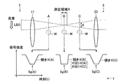
送光部3は、測定領域Rにて焦点を結ぶビームLB2を成形すると共に測定領域RにてビームLB2を走査する。送光部3は、図2に示すように、発光素子9、ミラー11、モータ13、ポリゴンミラー15、コリメータレンズ(f−θレンズ)17、キャビネット19、タイミング用フォトダイオード23、及びアンプ23Aを有する。発光素子9は、例えば、半導体レーザにて構成されている。ミラー11は、発光素子9から出射されたビームLB1を反射する。ポリゴンミラー15は、モータ13により矢印方向に高速回転された状態で、ミラー11により反射されたビームLB1が照射される。コリメータレンズ17は、ポリゴンミラー15で反射されたビームLB1を集光させてビームLB2にする。上記構成において、ポリゴンミラー15の回転により、ビームLB2は、測定領域Rを縦方向に一定速度で走査するように照射される。また、コリメータレンズ17によって、ビームLB2は、測定領域Rにて焦点を結ぶ。
The light transmitting
キャビネット19は、発光素子9、ミラー11、モータ13、ポリゴンミラー15、及びコリメータレンズ17、タイミング用フォトダイオード23、及びアンプ23Aを収容する。保護ガラス21は、キャビネット19の一方の側面に、コリメータレンズ17と対向するように嵌め込まれている。すなわち、ビームLB2は、保護ガラス21を透過して測定領域Rに照射される。タイミング用フォトダイオード23は、ポリゴンミラー15で反射されたビームLB1の有効走査範囲外に配置され、一回分の走査の開始又は終了を検出し、それらに基づくタイミング信号TSをアンプ23Aに入力する。アンプ23Aは、タイミング信号TSを増幅して、制御部7に出力する。
The
受光部5は、測定領域Rを通過したビームLB2を受光し、その受光したビームLB2に基づく受光信号Sgを出力する。受光部5は、図2に示すように、集光レンズ25、受光素子27、アンプ29、キャビネット31、及び保護ガラス33を有する。集光レンズ25は、走査領域Rを通過した走査ビームLB2を集光する。受光素子27は、集光レンズ25にて集光されたビームLB2を受光して受光信号Sgを出力する。アンプ29は、受光信号Sgを増幅する。キャビネット31は、集光レンズ25、受光部27、及びアンプ29を収容する。保護ガラス33は、キャビネット31の一方の側面に、集光レンズ25と対向するように嵌め込まれている。すなわち、測定領域Rを通過したビームLB2は、保護ガラス33を透過して集光レンズ25に入射する。
The
制御部7は、図2に示すように、クロック信号発振器39、カウンタ41、及び分周回路43を備える。クロック信号発信器39は、アンプ23Aにより増幅されたタイミング信号TSを受け付け、その信号に基づき、クロック信号CKを出力する。カウンタ41は、アンプ29により増幅された受光信号Sg、クロック信号発振器39で生成されたクロック信号CK、及びアンプ23Aにより増幅されたタイミング信号TSの入力を受け付ける。なお、カウンタ41は、ビームLB2で測定対象物Wを含む測定領域Rを走査したときに、測定対象物WによりビームLB2が遮られる等による受光信号Sgの変化に基づき、クロック信号CKを計数する。分周回路43は、クロック信号発振器39からのクロック信号CKの入力を受け付ける。分周回路43からの出力信号は、モータ13の回転同期に利用される。
As shown in FIG. 2, the
また、制御部7は、図2に示すように、CPU45、記憶部47、表示部49、設定キー51、メインバス53、及び入出力インターフェース55を備える。CPU45は、アンプ29からの受光信号Sg、及びアンプ23Aからのタイミング信号TSを受け付け、それら信号に基づき測定に必要な各種制御を実行する。CPU45は、受光信号Sgに基づき測定対象物Wの寸法Lを示す測定値Dを算出する。また、CPU45は、ビームLB2を走査する単位時間に対する受光信号Sgの強度の変化量(傾き)に基づき、測定値Dを補正する。より具体的には、CPU45は、ビームLB2が測定対象物Wに当たり始めるときに生じる受光信号Sgの信号強度の傾きに基づき、測定値Dを補正する。
Further, as shown in FIG. 2, the
記憶部47は、測定に必要な各種データ、プログラム等を記憶する。表示部49は、測定値Dを表示する。設定キー51は、測定に必要な各種設定を入力するためのものである。メインバス53は、CPU45、記憶部47、カウンタ41を電気的に互いに接続している。入出力インターフェース55は、表示部49及び設定キー51をメインバス53に接続している。
The
[第1実施形態に係る光学式測定装置1の動作]
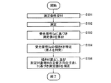
次に、第1実施形態に係る光学式測定装置1の動作について説明する。図3は、第1実施形態に係る光学式測定装置1の動作を示すフローチャートである。なお、図3に示す動作は、制御部7にて、CPU45が記憶部47から各種プログラムを読み出し、実行することによりなされる。
[Operation of
Next, the operation of the
先ず、制御部7は、図3に示すように、設定キー51にて測定条件を受け付ける(ステップS101)。次に、制御部7は、測定を実行する(ステップS102)。続いて、制御部7は、受光信号Sgに基づき、測定値Dを算出する(ステップS103)。
First, as shown in FIG. 3, the
続いて、制御部7は、受光信号Sgの傾きKを特定する(ステップS104)。ここで、傾きKは、ビームLB2を走査する単位時間に対する受光信号Sgの強度の変化量である。次に、制御部7は、傾きKに基づき測定値Dを補正する(ステップS106)。以上で、制御部7の動作は終了する。
Subsequently, the
次に、図4を参照して、上記ステップS102、及びステップS103の処理を具体的に説明する。ここでは、測定対象物Wは図4に示すように円筒形状を有し、紙面垂直方向を長手方向として配置されているものとする。図4は、第1実施形態に係る光学式測定装置1の測定の概略を示す図である。図4に示すように、測定(ステップS102)は、ビームLB2を走査し、測定領域Rを通過したビームLB2を検出することにより実行される。受光信号Sg(Sg(A)〜Sg(C))は、図4に示すように、測定対象物Wの形状に従って下に凹な波形となる。この受光信号Sgの下に凹な波形を解析することにより、測定値Dが算出される(ステップS103)。
Next, with reference to FIG. 4, the process of the said step S102 and step S103 is demonstrated concretely. Here, it is assumed that the measurement object W has a cylindrical shape as shown in FIG. 4 and is arranged with the direction perpendicular to the paper surface as the longitudinal direction. FIG. 4 is a diagram showing an outline of the measurement by the
続いて、図4及び図5を参照して、上記ステップS104の処理を具体的に説明する。図5は、受光信号Sgの拡大図である。上述したように、ビームLB2の焦点は、コリメータレンズ17によって測定領域Rに設定されるので、ビームLB2の径は、測定領域Rの位置B(焦点位置)にて最小となり、測定領域Rの位置Bから離れる程大きくなる。よって、例えば、位置Bから離れた位置A,CのビームLB2の径は、位置BのビームLB2の径よりも大きくなる。
Next, with reference to FIGS. 4 and 5, the process of step S104 will be specifically described. FIG. 5 is an enlarged view of the light reception signal Sg. As described above, since the focal point of the beam LB2 is set in the measurement region R by the
ここで、位置A〜Cに測定対象物Wを配置した際に、測定により得られる受光信号Sgをそれぞれ、受光信号Sg(A)〜Sg(C)とする。このような受光信号Sg(A)〜Sg(C)の傾きK(A)〜K(C)は、焦点位置からの距離に依存するビームLB2の径dによって変化し、K(B)>K(A)、K(B)>K(C)となる。 Here, when the measurement object W is arranged at the positions A to C, the light reception signals Sg obtained by the measurement are respectively referred to as light reception signals Sg (A) to Sg (C). The inclinations K (A) to K (C) of such light reception signals Sg (A) to Sg (C) vary depending on the diameter d of the beam LB2 depending on the distance from the focal position, and K (B)> K (A), K (B)> K (C).
例えば、制御部7は、受光信号Sgの信号強度の50%を閾値に設定して、その閾値に基づき受光信号Sgを2値化する。そして、制御部7は、2値化された受光信号Sgに基づきクロック信号CKを計数して、測定値Dを求める。したがって、測定値Dは、ビームLB2の径dの変化による影響を受けにくいはずである。しかしながら、閾値設定のばらつき、あるいは光学的要因等により、測定値Dは、ビームLB2の径dの変化による影響を受ける。
For example, the
傾きKは、具体的に以下のように決定する。すなわち、制御部7は、図5に示すように、受光信号Sgの信号強度に対して第1閾値Th1、第2閾値Th2(Th2<Th1)を設定する。続いて、制御部7は、ビームLB2の走査に伴って受光信号Sgの信号強度が第1閾値Th1となった時刻t1、及び受光信号Sgの信号強度が第2閾値Th2となった時刻t2を記憶する。そして、制御部7は、時刻t1と時刻t2との差Δを求める。この差Δは、第1閾値Th1から第2閾値Th2になる時間を示すので、差Δに基づき傾きKが特定される。すなわち、差Δは、焦点位置である位置Bから測定対象物Wがどの程度ずれて配置されているかを示す尺度となる。
The inclination K is specifically determined as follows. That is, as shown in FIG. 5, the
次に、図6及び図7を参照して、上記ステップS105の処理を具体的に説明する。図6は、測定対象物Wの位置に対する差Δの相対比、及び測定対象物Wの寸法Lを示す図である。図6に示す横軸は、測定対象物Wの横方向の位置を示し、測定領域Rの中心位置(焦点位置)を「0」とする。また、図6に示す縦軸は、位置「0」における差Δに対する各位置における差Δの比(差Δの相対比)、及び測定対象物Wの寸法Lを示す。図7は、記憶部47に格納されたテーブルTaを示す図である。
Next, with reference to FIGS. 6 and 7, the process of step S105 will be specifically described. FIG. 6 is a diagram illustrating a relative ratio of the difference Δ with respect to the position of the measurement object W and a dimension L of the measurement object W. The horizontal axis shown in FIG. 6 indicates the horizontal position of the measurement object W, and the center position (focus position) of the measurement region R is “0”. 6 indicates the ratio of the difference Δ at each position to the difference Δ at the position “0” (the relative ratio of the difference Δ) and the dimension L of the measurement target W. FIG. 7 is a diagram illustrating the table Ta stored in the
図6に示すように、測定対象物Wが測定領域Rの中心位置(焦点位置)から離れて位置するほど、差Δの相対比、及び測定対象物Wの寸法Lは増加する。これに対して、制御部7における記憶部47は、図7に示すように、差Δの相対比に対応する測定値Dの補正係数を示すテーブルTaを有している。補正係数は、以下に示す(数式1)で表される。なお、テーブルTaは、事前に求められた差Δに対する測定値Dの誤差率に基づき作成される。例えば、テーブルTaを作成する際、焦点位置から測定対象物Wを1mmずらす毎に測定を行う。
As shown in FIG. 6, the relative ratio of the difference Δ and the dimension L of the measurement object W increase as the measurement object W is located farther from the center position (focal position) of the measurement region R. On the other hand, as shown in FIG. 7, the
補正係数=焦点位置における測定値/焦点位置からずらした位置の測定値…(数式1) Correction coefficient = Measured value at the focal position / Measured value at a position shifted from the focal position (Equation 1)
制御部7は、以下に示す(数式2)のように、差Δの相対比に基づき、図7に示すテーブルTaを参照して、測定値Dを補正する。
The
補正後の測定値=補正前の測定値×差Δの相対比に対するテーブルTaの補正係数…(数式2) Correction value after correction = measurement value before correction × correction coefficient of table Ta with respect to relative ratio of difference Δ (Expression 2)
[第1実施形態に係る光学式測定装置1の効果]
第1実施形態に係る光学式測定装置1は、傾きK(差Δ)に基づき、測定値Dを補正することができる。すなわち、光学式測定装置1は、測定対象物Wの横方向のずれ量に基づく補正を可能とする。よって、測定対象物Wが振動等により測定中に測定領域Rから外れる(焦点位置から離れる)場合であっても、光学式測定装置1は、高精度な測定を行うことができる。
[Effect of the
The
また、第1実施形態に係る光学式測定装置1は、傾きK(差Δ)に基づき、焦点位置を検出することができる。
Further, the
また、第1実施形態に係る光学式測定装置1は、制御部7による処理を用いて補正を行うので、従来の構成から新たにハードウェアに変更を加える必要がない。したがって、光学式測定装置1は、容易に且つ安価に製造することができる。
In addition, since the
[第2実施形態]
[第2実施形態に係る光学式測定装置の動作]
次に、図8〜図10を参照して、第2実施形態に係る光学式測定装置の動作について説明する。図8は、第2実施形態に係る光学式測定装置の動作を示すフローチャートである。図9は、差Δに対する測定対象物Wの測定値Dの誤差率を示す図である。図10は、記憶部47に格納されたテーブルTa(1)〜Ta(n)を示す図である。なお、第2実施形態において、第1実施形態と同様の構成については、同一符号を付し、その説明を省略する。
[Second Embodiment]
[Operation of Optical Measuring Device According to Second Embodiment]
Next, the operation of the optical measurement device according to the second embodiment will be described with reference to FIGS. FIG. 8 is a flowchart showing the operation of the optical measurement apparatus according to the second embodiment. FIG. 9 is a diagram illustrating an error rate of the measurement value D of the measurement object W with respect to the difference Δ. FIG. 10 is a diagram showing the tables Ta (1) to Ta (n) stored in the
第2実施形態に係る光学式測定装置は、図8に示すように、第1実施形態のステップS105の代わりに、傾きK、及び測定対象物Wの走査方向の寸法Lに基づき、測定値Dを補正する(ステップS106)。以上で、第2実施形態に係る光学式測定装置の動作は、終了する。 As shown in FIG. 8, the optical measurement device according to the second embodiment is based on the inclination K and the dimension L in the scanning direction of the measurement target W instead of step S105 of the first embodiment. Is corrected (step S106). Above, operation | movement of the optical measuring device which concerns on 2nd Embodiment is complete | finished.
図9に示すように、第1実施形態と同様、差Δの増加に伴い、誤差率が増加する。さらに、図9に示すように、誤差率の増加は、測定対象物Wの寸法L(走査方向の寸法)によって異なる。これに対して、制御部7において記憶部47は、図10に示すように、各々の測定対象物Wの寸法Lに対応する複数のテーブルTa(1)〜Ta(n)を有する。各テーブルTa(1)〜Ta(n)は、差Δの相対比に対応する測定値Dの補正係数を有する。制御部7は、図10に示す複数のテーブルTa(1)〜Ta(n)を参照して、各々の測定対象物Wの寸法Lに対応して、測定値Dを補正する。
As shown in FIG. 9, as in the first embodiment, the error rate increases as the difference Δ increases. Furthermore, as shown in FIG. 9, the increase in the error rate varies depending on the dimension L (dimension in the scanning direction) of the measurement object W. On the other hand, in the
[第2実施形態に係る光学式測定装置の効果]
第2実施形態に係る光学式測定装置は、測定対象物Wの寸法に対応して、測定値Dを補正するので、第1実施形態よりも広範囲、高精度な補正が可能となる。
[Effects of the optical measurement apparatus according to the second embodiment]
Since the optical measurement apparatus according to the second embodiment corrects the measurement value D in accordance with the dimension of the measurement object W, it is possible to perform correction over a wider range and with higher accuracy than in the first embodiment.
[その他の実施形態]
以上、発明の実施形態を説明したが、本発明はこれらに限定されるものではなく、発明の趣旨を逸脱しない範囲内において、種々の変更、追加等が可能である。
[Other Embodiments]
As mentioned above, although embodiment of invention was described, this invention is not limited to these, A various change, addition, etc. are possible within the range which does not deviate from the meaning of invention.
例えば、第1実施形態において、測定によって求めた差Δの相対比に対応する補正係数がテーブルTaにない場合がある。この場合、制御部7は、測定によって求めた差Δの相対比の前後の値となるテーブルTaに記憶された2つの差Δの相対比を使用して、直線補間により補正を行ってもよい。
For example, in the first embodiment, the table Ta may not have a correction coefficient corresponding to the relative ratio of the difference Δ obtained by measurement. In this case, the
例えば、第2実施形態において、測定対象物Wの寸法Lに対応するテーブルTa(1)〜Ta(n)がない場合がある。この場合、制御部7は、測定対象物Wの寸法Lの前後に対応する2つのテーブルTa(k)、Ta(k+1)を使用して、直線補間により補正を行ってもよい。
For example, in the second embodiment, there may be no tables Ta (1) to Ta (n) corresponding to the dimension L of the measurement object W. In this case, the
例えば、上記実施形態において、テーブルTa、Ta(1)〜Ta(n)は、制御部7の記憶部47に格納されている。しかしながら、本発明において、テーブルTa、Ta(1)〜Ta(n)は、記憶部47に格納さていなくともよい。すなわち、テーブルTa、Ta(1)〜Ta(n)は、光学式測定装置の外部に設けたコンピュータ(演算処理装置)に格納され、その外部のコンピュータにて制御部7の処理の一部が実行されてもよい。
For example, in the above embodiment, the tables Ta and Ta (1) to Ta (n) are stored in the
1…光学式測定装置、 3…送光部、 5…受光部、 7…制御部、 9…発光素子、 11…ミラー、 13…モータ、 15…ポリゴンミラー、 17…コリメータレンズ、 19…キャビネット、 21…保護ガラス、 23…タイミング用フォトダイオード、 23A…アンプ、 25…集光レンズ、 27…受光素子、 29…アンプ、 31…キャビネット、 33…保護ガラス、 39…クロック信号発振器、41…カウンタ、43…分周回路、45…CPU、 47…記憶部、 49…表示部、 51…設定キー、 53…メインバス、 55…入出力インターフェース。
DESCRIPTION OF
Claims (5)
前記測定領域を通過したビームを受光し、当該受光したビームに基づく受光信号を出力する受光部と、
前記受光信号に基づき前記測定対象物の寸法を示す測定値を算出する測定値算出部と、
前記ビームを走査する単位時間に対する前記受光信号の強度の変化量に基づき、前記測定値を補正する補正部と
を備えることを特徴とする光学式測定装置。 A light transmitting unit that shapes a beam focused in a measurement region where a measurement object is disposed and scans the beam in the measurement region;
A light receiving unit that receives the beam that has passed through the measurement region and outputs a light reception signal based on the received beam;
A measurement value calculation unit for calculating a measurement value indicating the dimension of the measurement object based on the light reception signal;
An optical measurement apparatus comprising: a correction unit that corrects the measurement value based on a change amount of the intensity of the light reception signal with respect to a unit time for scanning the beam.
ことを特徴とする請求項1記載の光学式測定装置。 The correction unit detects a first time when the light reception signal becomes a first threshold with the scanning of the beam, and a second time when the light reception signal becomes a second threshold with the scanning of the beam, The optical measurement apparatus according to claim 1, wherein the amount of change is specified based on the first time and the second time.
ことを特徴とする請求項1又は請求項2記載の光学式測定装置。 The optical measurement apparatus according to claim 1, wherein the correction unit corrects the measurement value based on a dimension of the measurement object in a scanning direction of the beam.
前記測定領域を通過したビームに基づく受光信号により前記測定対象物の寸法を示す測定値を算出するステップと、
前記ビームを走査する単位時間に対する前記受光信号の強度の変化量に基づき、前記測定値を補正するステップと
を備えることを特徴とする光学式測定方法。 Forming a focused beam in a measurement area where a measurement object is placed and scanning the beam in the measurement area;
Calculating a measurement value indicating a dimension of the measurement object by a light reception signal based on a beam that has passed through the measurement region;
And a step of correcting the measurement value based on an amount of change in intensity of the received light signal with respect to a unit time for scanning the beam.
測定対象物が配置される測定領域にて焦点を結ぶビームを成形すると共に前記測定領域にて前記ビームを走査するステップと、
前記測定領域を通過したビームに基づく受光信号により前記測定対象物の寸法を示す測定値を算出するステップと、
前記ビームを走査する単位時間に対する前記受光信号の強度の変化量に基づき、前記測定値を補正するステップと
を実行させるための光学式測定処理プログラム。 On the computer,
Forming a focused beam in a measurement area where a measurement object is placed and scanning the beam in the measurement area;
Calculating a measurement value indicating a dimension of the measurement object by a light reception signal based on a beam that has passed through the measurement region;
An optical measurement processing program for executing the step of correcting the measurement value based on a change amount of the intensity of the received light signal with respect to a unit time for scanning the beam.
Priority Applications (4)
| Application Number | Priority Date | Filing Date | Title |
|---|---|---|---|
| JP2009098113A JP2010249604A (en) | 2009-04-14 | 2009-04-14 | Optical measuring apparatus, optical measuring method, and optical measurement processing program |
| EP10159535A EP2241855B1 (en) | 2009-04-14 | 2010-04-09 | Optical measuring apparatus and method |
| AT10159535T ATE515678T1 (en) | 2009-04-14 | 2010-04-09 | OPTICAL MEASURING DEVICE AND MEASURING METHOD |
| US12/759,159 US7948642B2 (en) | 2009-04-14 | 2010-04-13 | Optical measuring apparatus, optical measuring method, and optical measurement processing program |
Applications Claiming Priority (1)
| Application Number | Priority Date | Filing Date | Title |
|---|---|---|---|
| JP2009098113A JP2010249604A (en) | 2009-04-14 | 2009-04-14 | Optical measuring apparatus, optical measuring method, and optical measurement processing program |
Publications (1)
| Publication Number | Publication Date |
|---|---|
| JP2010249604A true JP2010249604A (en) | 2010-11-04 |
Family
ID=42126385
Family Applications (1)
| Application Number | Title | Priority Date | Filing Date |
|---|---|---|---|
| JP2009098113A Withdrawn JP2010249604A (en) | 2009-04-14 | 2009-04-14 | Optical measuring apparatus, optical measuring method, and optical measurement processing program |
Country Status (4)
| Country | Link |
|---|---|
| US (1) | US7948642B2 (en) |
| EP (1) | EP2241855B1 (en) |
| JP (1) | JP2010249604A (en) |
| AT (1) | ATE515678T1 (en) |
Cited By (3)
| Publication number | Priority date | Publication date | Assignee | Title |
|---|---|---|---|---|
| DE102014209451A1 (en) | 2013-05-20 | 2014-11-20 | Mitutoyo Corporation | Optical measuring device |
| CN109211106A (en) * | 2017-06-30 | 2019-01-15 | 株式会社三丰 | Optical measuring apparatus |
| US20220163321A1 (en) * | 2020-11-20 | 2022-05-26 | Keyence Corporation | Optical measurement apparatus |
Families Citing this family (4)
| Publication number | Priority date | Publication date | Assignee | Title |
|---|---|---|---|---|
| CN102927920A (en) * | 2012-10-31 | 2013-02-13 | 昆山允可精密工业技术有限公司 | Cylindrical material measuring device |
| EP3450097A1 (en) * | 2017-09-05 | 2019-03-06 | Renishaw PLC | Non-contact optical tool setting apparatus and method |
| EP3537100B1 (en) * | 2018-03-01 | 2020-08-05 | Mitutoyo Corporation | Methods and apparatuses for refractive index measurement of transparent tube |
| JP7240937B2 (en) * | 2019-04-05 | 2023-03-16 | 株式会社ミツトヨ | Optical measuring device and optical measuring method |
Family Cites Families (6)
| Publication number | Priority date | Publication date | Assignee | Title |
|---|---|---|---|---|
| US3905705A (en) * | 1972-01-31 | 1975-09-16 | Techmet Co | Optical measuring apparatus |
| US4007992A (en) * | 1975-06-02 | 1977-02-15 | Techmet Company | Light beam shape control in optical measuring apparatus |
| JPH06249618A (en) | 1993-03-01 | 1994-09-09 | Mitsutoyo Corp | Optical dimension measuring instrument |
| JPH0915156A (en) * | 1995-06-28 | 1997-01-17 | Kdk Corp | Spectroscopic measuring method and measuring device |
| JP4191953B2 (en) | 2002-05-09 | 2008-12-03 | 株式会社ミツトヨ | Calibration method of laser scanning dimension measuring machine |
| JP2006038487A (en) | 2004-07-22 | 2006-02-09 | Mitsutoyo Corp | Optical measuring instrument |
-
2009
- 2009-04-14 JP JP2009098113A patent/JP2010249604A/en not_active Withdrawn
-
2010
- 2010-04-09 EP EP10159535A patent/EP2241855B1/en not_active Not-in-force
- 2010-04-09 AT AT10159535T patent/ATE515678T1/en not_active IP Right Cessation
- 2010-04-13 US US12/759,159 patent/US7948642B2/en not_active Expired - Fee Related
Cited By (6)
| Publication number | Priority date | Publication date | Assignee | Title |
|---|---|---|---|---|
| DE102014209451A1 (en) | 2013-05-20 | 2014-11-20 | Mitutoyo Corporation | Optical measuring device |
| US9423241B2 (en) | 2013-05-20 | 2016-08-23 | Mitutoyo Corporation | Optical measuring apparatus |
| CN109211106A (en) * | 2017-06-30 | 2019-01-15 | 株式会社三丰 | Optical measuring apparatus |
| CN109211106B (en) * | 2017-06-30 | 2021-09-07 | 株式会社三丰 | Optical measuring device |
| US20220163321A1 (en) * | 2020-11-20 | 2022-05-26 | Keyence Corporation | Optical measurement apparatus |
| US11668559B2 (en) * | 2020-11-20 | 2023-06-06 | Keyence Corporation | Optical measurement apparatus |
Also Published As
| Publication number | Publication date |
|---|---|
| US7948642B2 (en) | 2011-05-24 |
| US20100259769A1 (en) | 2010-10-14 |
| EP2241855B1 (en) | 2011-07-06 |
| EP2241855A1 (en) | 2010-10-20 |
| ATE515678T1 (en) | 2011-07-15 |
Similar Documents
| Publication | Publication Date | Title |
|---|---|---|
| JP2010249604A (en) | Optical measuring apparatus, optical measuring method, and optical measurement processing program | |
| US8705049B2 (en) | Three-dimensional shape measuring apparatus, three-dimensional shape measuring method, and three-dimensional shape measuring program | |
| US20150276390A1 (en) | Correction device and correction method for optical measuring apparatus | |
| JP2008026243A (en) | Three-dimensional shape measuring system and method | |
| JP6178617B2 (en) | Optical measuring device | |
| JP6481034B2 (en) | Defocus detection method | |
| JP5327003B2 (en) | Surface shape measuring apparatus and method | |
| JP2014232005A (en) | Measurement device | |
| JP2017003461A (en) | Distance measurement device | |
| JP5679907B2 (en) | Laser radar equipment | |
| JP2010223950A (en) | Optical displacement meter | |
| JP2007322177A (en) | Laser light irradiation measuring device | |
| JP2011106817A (en) | Optical dimension measuring device | |
| JP5929518B2 (en) | Surface shape measuring method and surface shape measuring apparatus | |
| JP5431221B2 (en) | Distance measuring device | |
| JP6519860B2 (en) | Non-contact shape measuring apparatus and scanning lens aberration correction method | |
| JP2010182262A (en) | Information reading apparatus | |
| JP5358383B2 (en) | Displacement sensor | |
| JP2002139311A (en) | Light beam irradiation measuring device | |
| JP7271066B2 (en) | Optical measuring device | |
| JP7411887B2 (en) | Laser processing equipment and focus control method for laser processing equipment | |
| US11530911B2 (en) | Optical measuring device and optical measuring method | |
| JP7237766B2 (en) | Optical measuring device | |
| JPWO2018008393A1 (en) | Laser radar equipment | |
| JP3751610B2 (en) | Displacement measuring device |
Legal Events
| Date | Code | Title | Description |
|---|---|---|---|
| A300 | Application deemed to be withdrawn because no request for examination was validly filed |
Free format text: JAPANESE INTERMEDIATE CODE: A300 Effective date: 20120703 |