JP2010242113A - In-magnetic field heat treatment apparatus, and in-magnetic field heat treatment method - Google Patents
In-magnetic field heat treatment apparatus, and in-magnetic field heat treatment method Download PDFInfo
- Publication number
- JP2010242113A JP2010242113A JP2009088787A JP2009088787A JP2010242113A JP 2010242113 A JP2010242113 A JP 2010242113A JP 2009088787 A JP2009088787 A JP 2009088787A JP 2009088787 A JP2009088787 A JP 2009088787A JP 2010242113 A JP2010242113 A JP 2010242113A
- Authority
- JP
- Japan
- Prior art keywords
- magnetic field
- heat treatment
- permanent magnet
- treatment apparatus
- processed
- Prior art date
- Legal status (The legal status is an assumption and is not a legal conclusion. Google has not performed a legal analysis and makes no representation as to the accuracy of the status listed.)
- Granted
Links
Images


Abstract
Description
本発明は、磁場中熱処理装置、及び、磁場中熱処理方法に関する。 The present invention relates to a heat treatment apparatus in a magnetic field and a heat treatment method in a magnetic field.
半導体の記憶素子の一つであるMRAM(Magnetic Random Access Memory)の製造工程には、半導体基板の内部にある記憶素子の役割を担う磁性体膜を磁場中で熱処理し、磁性体膜を初期化(磁化)する工程がある。すなわち、この工程では、磁束密度1〜3テスラという非常に高い磁場中で、半導体基板を数時間の間150〜400℃に加熱する。 In the manufacturing process of MRAM (Magnetic Random Access Memory) which is one of the semiconductor memory elements, the magnetic film that plays the role of the memory element inside the semiconductor substrate is heat-treated in a magnetic field to initialize the magnetic film. There is a step of (magnetization). That is, in this step, the semiconductor substrate is heated to 150 to 400 ° C. for several hours in a very high magnetic field with a magnetic flux density of 1 to 3 Tesla.
一般的に、半導体の磁場中熱処理工程で使用される磁場中熱処理装置は、磁場の発生に超大型の永久磁石や超電導磁石を使用する、多数の半導体基板の同時処理が可能なバッチ型炉方式の磁場中熱処理装置である。
ただし、このバッチ型炉方式の磁場中熱処理装置は、装置の利用効率の観点からみれば、磁場中熱処理を行う時間以外に、半導体基板を処理室に導入、加熱、冷却、搬出する時間が必要であり、コストパフォーマンスが悪い。また、生産効率化の面では、半導体基板を1枚ずつ処理し装置の仕掛かりを低減する、いわゆる枚葉装置が主流になりつつある。そのため、工場のライン構築上でも、バッチ型炉方式の磁場中熱処理装置が、生産効率の面でネックになる。
In general, the heat treatment equipment in a magnetic field used in the heat treatment process of a semiconductor in a magnetic field uses a very large permanent magnet or superconducting magnet to generate a magnetic field, and a batch furnace system that can simultaneously process a large number of semiconductor substrates. This is a heat treatment apparatus in a magnetic field.
However, from the viewpoint of the utilization efficiency of this batch furnace type magnetic field heat treatment apparatus, in addition to the time for performing heat treatment in the magnetic field, it is necessary to take time to introduce, heat, cool, and carry out the semiconductor substrate into the processing chamber. The cost performance is bad. In terms of production efficiency, so-called single wafer devices, which process semiconductor substrates one by one and reduce the number of devices in progress, are becoming mainstream. Therefore, a batch furnace type magnetic field heat treatment apparatus becomes a bottleneck in terms of production efficiency even when building a factory line.
例えば、特許文献1には、熱処理炉内に磁場を発生させて、磁場中で被処理物の熱処理を行う磁場中熱処理装置の技術が開示されている。
この磁場中熱処理装置は、水平方向に中心軸線を有するように横置された筒状熱処理炉の外側に、同一中心軸線を有する筒状のソレノイド型超電導磁石を配置して、熱処理炉内に中心軸線と平行な均一磁場を形成すると共に、熱処理炉の長軸方向に加熱手段を配置してなることを特徴とする。
次に、上記のソレノイド型超電導磁石を利用した磁場中熱処理装置について、図面を参照して説明する。
For example, Patent Document 1 discloses a technique of a magnetic field heat treatment apparatus that generates a magnetic field in a heat treatment furnace and heats an object to be processed in the magnetic field.
In this magnetic field heat treatment apparatus, a cylindrical superconducting magnet having the same center axis is disposed outside a cylindrical heat treatment furnace that is horizontally disposed so as to have a central axis in the horizontal direction, and the center is placed in the heat treatment furnace. A uniform magnetic field parallel to the axis is formed, and heating means is arranged in the major axis direction of the heat treatment furnace.
Next, a heat treatment apparatus in a magnetic field using the solenoid type superconducting magnet will be described with reference to the drawings.
(本発明に関連する磁場中熱処理装置)
図6は、本発明に関連する磁場中熱処理装置の概略断面図である。
図6において、本発明に関連する磁場中熱処理装置100は、ソレノイド型超電導磁石101、補助超電導コイル102a、102b、熱処理炉103、被処理物搬送装置105、及び、加熱手段106などを備えている。
(Heat treatment apparatus in a magnetic field related to the present invention)
FIG. 6 is a schematic cross-sectional view of a heat treatment apparatus in a magnetic field related to the present invention.
In FIG. 6, a heat treatment apparatus 100 in a magnetic field related to the present invention includes a solenoid type superconducting magnet 101, auxiliary superconducting coils 102a and 102b, a heat treatment furnace 103, a workpiece transfer apparatus 105, a heating means 106, and the like. .
ソレノイド型超電導磁石101は、円筒状としてあり、その中心軸線が水平になるように横置されている。このソレノイド型超電導磁石101の磁場の方向は、図示してないが、ソレノイド型超電導磁石101の中心軸線と平行である。
また、ソレノイド型超電導磁石101の両端部には、補助超電導コイル102a、102bが配設されている。この補助超電導コイル102a、102bは、ソレノイド型超電磁石101の磁力線方向とは逆向きの磁力線を発生させる。これにより、ソレノイド型超電導磁石101から外部に漏洩する磁場を打ち消して、漏洩磁場を低減させることができる。
Solenoid superconducting magnet 101 has a cylindrical shape, and is placed side by side so that its central axis is horizontal. Although the direction of the magnetic field of the solenoid type superconducting magnet 101 is not shown, it is parallel to the central axis of the solenoid type superconducting magnet 101.
In addition, auxiliary superconducting coils 102 a and 102 b are disposed at both ends of the solenoid type superconducting magnet 101. The auxiliary superconducting coils 102 a and 102 b generate magnetic lines of force that are opposite to the direction of the magnetic lines of force of the solenoid type superelectromagnet 101. Thereby, the magnetic field leaking to the outside from the solenoid type superconducting magnet 101 can be canceled out, and the leakage magnetic field can be reduced.
熱処理炉103は、石英あるいはアルミナ等の耐熱性の材料からなり、筒状としてある。また、熱処理炉103は、外周面に、電気ヒーターなどの加熱手段106が設けられている。この熱処理炉103は、筒状の中心軸線がソレノイド型超電導磁石101の中心軸線と同一になるように、ソレノイド型超電導磁石101の内部空間内に、配置されている。
また、熱処理炉103は、通常、入口側(図中左側)の加熱手段106が密に配置され、出口側の加熱手段106が疎に配置されている。これにより、炉内の長手方向に、所定の温度分布を形成することができる。
なお、熱処理炉103は、真空炉又は不活性ガス炉として、使用可能である。ただし、真空炉として使用する場合には、半導体基板104を間欠挿入、及び、間欠排出となり連続運転が困難になるのみならず、半導体基板104の加熱は、輻射熱のみによる加熱となる。したがって、通常、対流伝熱と伝導伝熱も生じる不活性ガス炉として使用される。
The heat treatment furnace 103 is made of a heat resistant material such as quartz or alumina and has a cylindrical shape. The heat treatment furnace 103 is provided with a heating means 106 such as an electric heater on the outer peripheral surface. The heat treatment furnace 103 is arranged in the internal space of the solenoid type superconducting magnet 101 so that the cylindrical center axis is the same as the center axis of the solenoid type superconducting magnet 101.
Further, in the heat treatment furnace 103, the heating means 106 on the inlet side (left side in the drawing) is usually densely arranged, and the heating means 106 on the outlet side is sparsely arranged. Thereby, a predetermined temperature distribution can be formed in the longitudinal direction in the furnace.
The heat treatment furnace 103 can be used as a vacuum furnace or an inert gas furnace. However, when used as a vacuum furnace, the
また、被処理物搬送装置105は、ウエーハなどの半導体基板104を載置して移動させる載置部材などを備えており、載置部材が、熱処理炉103の内部空間内を移動する。すなわち、この被処理物搬送装置105は、載置部材に載置された半導体基板104を、移動方向(左側から右側へ)に沿って移動させる。
Further, the workpiece transfer apparatus 105 includes a mounting member for mounting and moving a
ここで、半導体基板104の磁場中熱処理においては、半導体基板104の平面が、磁場の方向と平行に保持される必要がある。
すなわち、代表的なウエーハの形状(一部に端面切削線部を有する薄い円板状)としてある半導体基板104は、端面切削線部を下にして、該端面切削線部がソレノイド型超電導磁石101の磁場の方向と平行となるように、搬送装置105に載置されている。これにより、半導体基板104の平面は、磁場の方向と平行に保持される。
Here, in the heat treatment in the magnetic field of the
That is, the
上記構成の磁場中熱処理装置100は、円筒状のソレノイド型超電導磁石101を利用し、半導体基板104をソレノイド型超電導磁石101の内部で加熱しながら、ソレノイド型超電導磁石101の中心軸方向へ一定速度で搬送することによって、半導体基板104を1〜複数(たとえば、9)枚ずつ処理することができる。
The magnetic field heat treatment apparatus 100 configured as described above uses a cylindrical solenoid type superconducting magnet 101 and heats the
さらに、特許文献2には、減圧された容器内に配置された被処理部材に磁界を印加しながら加熱処理を行う磁界中熱処理装置の技術が開示されている。
この磁界中熱処理装置は、容器の周囲に加熱用のヒーターを配置すると共に、磁界発生手段として超伝導磁石装置を配置したことを特徴としている。
Furthermore,
This magnetic field heat treatment apparatus is characterized in that a heater for heating is disposed around the container, and a superconducting magnet device is disposed as a magnetic field generating means.
また、特許文献3には、処理対象が熱処理される領域における磁界発生手段により発生する磁界の方向と、処理対象を熱処理容器内へと搬送する搬送手段の搬送方向とは、互いに平行で、かつ、熱処理装置全体の水平方向に対して平行であり、処理対象は、その主面が熱処理領域にて磁界発生手段による発生する磁界の方向と平行になるように配置して熱処理する熱処理装置の技術が開示されている。
In
しかしながら、上述した磁場中熱処理装置100は、ソレノイド型超電導磁石101を駆動するための電力、発熱するソレノイド型超電導磁石101を冷却する冷却水を循環させるための電力、及び、昇温された冷却水を冷却するための電力などが大量に必要であった。すなわち、世界的に地球温暖化を防止することの必要性が叫ばれている中、省エネルギー化を図ることができないといった問題があった。 However, the above-described heat treatment apparatus 100 in the magnetic field has the power for driving the solenoid type superconducting magnet 101, the power for circulating the cooling water for cooling the solenoid type superconducting magnet 101 that generates heat, and the cooling water that has been heated. A large amount of power was needed to cool the battery. That is, there is a problem that energy saving cannot be achieved while the necessity of preventing global warming is being screamed worldwide.
また、磁場中熱処理装置100は、ソレノイド型超電導磁石101の磁場の方向と平行となるように、複数の半導体基板104が移動方向と直交する方向に並べられて載置されているので、ソレノイド型超電導磁石101の内部を移動する半導体基板104の数量や投入タイミングなどが、半導体基板104の幅などで制限されてしまい、生産効率を向上させることができないといった問題があった。
In addition, since the plurality of
さらに、磁場熱処理装置100は、移動方向に対して、複数の半導体基板104が密集した部分と、これらの部分の間のほぼ全く半導体基板104が存在しない部分とが、交互に並んだ状態で移動するので、温度分布に悪影響を及ぼしたり、あるいは、半導体基板104の先端部分と後端部分とで温度プロファイルが異なってしまい、品質管理上の信頼性が低下するといった問題があった。
Furthermore, the magnetic field heat treatment apparatus 100 moves in a state in which a portion where a plurality of
また、上述したように、磁場中熱処理装置は、磁場の発生に超大型の永久磁石や超電導磁石を使用するが、たとえば、超大型の永久磁石を使用する場合であっても、小型化や軽量化を図ることが要望されている。
なお、特許文献2、3の技術は、本発明に関連する技術ではあるもの、上記の課題を解決することはできない。
In addition, as described above, the heat treatment apparatus in a magnetic field uses a very large permanent magnet or a superconducting magnet for generating a magnetic field. For example, even if a very large permanent magnet is used, it is reduced in size and weight. There is a demand for improvement.
In addition, although the technique of
本発明は、以上のような問題を解決するために提案されたものであり、生産効率や品質管理上の信頼性を向上させることができ、省エネルギー化、小型化や軽量化を図ることができる磁場中熱処理装置、及び、磁場中熱処理方法の提供を目的とする。 The present invention has been proposed to solve the above-described problems, can improve production efficiency and reliability in quality control, and can achieve energy saving, downsizing, and weight reduction. An object is to provide a heat treatment apparatus in a magnetic field and a heat treatment method in a magnetic field.
上記目的を達成するため、本発明の磁場中熱処理装置は、中心軸に対し垂直方向に内部磁場が発生する筒状の永久磁石と、この永久磁石の内面に設けられた断熱部と、この断熱部の内側に設けられた予備加熱部、主加熱部、及び、冷却部と、前記永久磁石の内部空間において、被処理体が前記内部磁場の磁場方向と平行となる状態で、該被処理体を、前記永久磁石の中心軸方向に搬送する搬送部とを備えた構成としてある。 In order to achieve the above object, a magnetic field heat treatment apparatus according to the present invention includes a cylindrical permanent magnet that generates an internal magnetic field in a direction perpendicular to the central axis, a heat insulating portion provided on the inner surface of the permanent magnet, and the heat insulating material. In a state where the object to be processed is parallel to the magnetic field direction of the internal magnetic field in the internal space of the permanent magnet, the preheating part, the main heating part, and the cooling part provided inside the part. Is provided with a transport unit that transports the permanent magnet in the central axis direction of the permanent magnet.
また、本発明の磁場中熱処理方法は、中心軸に対し垂直方向に内部磁場が発生する筒状の永久磁石と、この永久磁石の内面に設けられた断熱部と、この断熱部の内側に設けられた予備加熱部、主加熱部、及び、冷却部と、前記永久磁石の内部空間において、被処理体を搬送する搬送部とを用い、前記搬送部が、前記被処理体が前記内部磁場の磁場方向と平行となる状態で、該被処理体を、前記永久磁石の中心軸方向に搬送する方法としてある。 The heat treatment method in a magnetic field of the present invention includes a cylindrical permanent magnet that generates an internal magnetic field in a direction perpendicular to the central axis, a heat insulating portion provided on the inner surface of the permanent magnet, and a heat insulating portion provided inside the heat insulating portion. The preheating unit, the main heating unit, and the cooling unit, and a transport unit that transports the object to be processed in the internal space of the permanent magnet, the transport unit is configured so that the object to be processed has the internal magnetic field. In this method, the object to be processed is conveyed in the direction of the central axis of the permanent magnet in a state parallel to the magnetic field direction.
本発明の磁場中熱処理装置、及び、磁場中熱処理方法によれば、生産効率や品質管理上の信頼性を向上させることができ、省エネルギー化、小型化や軽量化を図ることができる。 According to the magnetic field heat treatment apparatus and magnetic field heat treatment method of the present invention, production efficiency and quality control reliability can be improved, and energy saving, size reduction, and weight reduction can be achieved.
[磁場中熱処理装置及び磁場中熱処理方法の第一実施形態]
図1は、本発明の第一実施形態にかかる磁場中熱処理装置の概略断面図である。
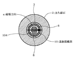
また、図2は、図1のA−A断面図である。
図1、2において、本実施形態の磁場中熱処理装置1は、永久磁石2、断熱部3、予備加熱ヒーター4、メインヒーター5、冷却部6、基板搭載部10を有するコンベア8、及び、磁気シールド11などを備えた構成としてある。
この磁場中熱処理装置1は、永久磁石2を利用し、半導体基板104を永久磁石2の内部で加熱しながら、永久磁石2の中心軸方向(処理方向)へ搬送することによって、半導体基板104を一枚ずつ連続的に処理する。
なお、本実施形態では、被処理体を半導体基板104としてあるが、これに限定されるものではない。
[First Embodiment of Magnetic Field Heat Treatment Apparatus and Magnetic Field Heat Treatment Method]
FIG. 1 is a schematic cross-sectional view of a magnetic field heat treatment apparatus according to the first embodiment of the present invention.
FIG. 2 is a cross-sectional view taken along the line AA in FIG.
1 and 2, a magnetic field heat treatment apparatus 1 according to the present embodiment includes a
This heat treatment apparatus 1 in a magnetic field utilizes the
In this embodiment, the object to be processed is the
(永久磁石)
永久磁石2は、円筒状としてあり、中心軸に対し垂直方向に内部磁場(通常、磁束密度1〜3テスラという非常に高い内部磁場)が発生する構成としてある。また、永久磁石2の内部磁場の方向は、磁場方向a(永久磁石2の中心軸方向と直交する方向であって、コンベア8と平行な方向(図2参照))である。したがって、後述するように、永久磁石2の内部磁場の方向は、半導体基板104の平面に平行となる。このようにすると、ソレノイド型超電導磁石101を駆動するための電力、発熱するソレノイド型超電導磁石101を冷却する冷却水を循環させるための電力、及び、昇温された冷却水を冷却するための電力など大量の電力を消費しなくてもすむので、省エネルギー化を図ることができる。
(permanent magnet)
The
ここで、好ましくは、永久磁石2が、ハルバック式永久磁石であるとよい。このハルバック式永久磁石は、所定の形状の永久磁石をハルバック型配列に配設した構成としてある。すなわち、ドーナツ状に、外部磁場の向きと同じになるように磁石を配列することにより、内径空間(ドーナツ状の内側)に非常に均一性の高い磁場を発生することができる。
Here, preferably, the
(断熱部)
断熱部3は、石英やアルミナ等の耐熱性の材料からなり、円筒状としてある。また、断熱部3は、永久磁石2の内側に装入されている。この断熱部3は、メインヒーター4と予備加熱ヒーター3とで発生する熱を、永久磁石2に対して断熱し、永久磁石2の熱による磁力の低下を防止する。
(Insulation part)
The
(加熱手段及び冷却部)
加熱手段としてのメインヒーター5及び予備加熱ヒーター4、並びに、冷却部6は、円筒状としてある。また、予備加熱ヒーター4、メインヒーター5及び冷却部6は、断熱部3の内側に、搬送方向に対してこの順番で装入されている。
メインヒーター5は、搬送される半導体基板104を所定の温度に加熱する。また、予備加熱ヒーター4は、半導体基板104に熱ストレスがかかり過ぎないように、通常、メインヒーター5より低い温度に設定されており、半導体基板104を予備的に加熱する。
また、冷却部6は、通常、冷却水などの冷媒によって冷却されており、予備加熱ヒーター4及びメインヒーター5によって加熱された半導体基板104を冷却する。
(Heating means and cooling part)
The
The
The
ここで、好ましくは、メインヒーター5が、搬送方向に並設された複数のヒーター(たとえば、5つのヒーター)を有し、これら複数のヒーターが、それぞれ温度制御されるとよい。このようにすると、半導体基板104を加熱する温度プロファイルを制御することが可能となり、各半導体基板104(たとえば、厚さや大きさなどの異なる半導体基板104)に適した加熱を行うことができる。
Here, it is preferable that the
(搬送手段)
本実施形態の搬送手段は、複数の基板搭載部10を有するコンベア8、コンベア8が掛けられるローラー7、及び、コンベア8を移動させるモーター9などを備えている。また、コンベア8や基板搭載部10の材料としては、永久磁石2の磁場の影響をうけないように、非磁性材料が用いられる。
(Conveying means)
The transport means of the present embodiment includes a
このコンベア8は、永久磁石2の中心軸方向である搬送方向に向けて、基板搭
載部10に搭載された半導体基板104を搬送する。また、基板搭載部10によって、半導体基板104は、端面切削線部を下にして、該端面切削線部が永久磁石2の内部磁場の方向(磁場方向a)と平行となるように、コンベア8に載置されている。これにより、半導体基板104の平面は、永久磁石2の内部磁場の方向(磁場方向a)と平行に保持される。
The
また、半導体基板104は、コンベア8の搬送方向に平面が直交する状態で、基板搭載部10に載置されるので、基板搭載部10どうしのピッチは、基板搭載部10の搬送方向の長さ+所定のクリアランスに設定されている。すなわち、磁場中熱処理装置1は、半導体基板104どうしの間隔を短くした状態(たとえば、20〜40mmの間隔)で搬送することができるので、図6に示す磁場中熱処理装置100と比べると、生産効率を向上させることができる。
さらに、本実施形態の磁場中熱処理装置1は、搬送方向に対して、所定の間隔(上記の短い間隔で)で半導体基板104を一枚ずつ連続的に投入することができるので、搬送方向の温度分布に悪影響を及ぼしたり、あるいは、半導体基板104の先端部分と後端部分とで温度プロファイルが異なるといった品質管理上の信頼性が低下するといった不具合を排除することができる。
Further, since the
Furthermore, since the heat treatment apparatus 1 in the magnetic field according to the present embodiment can continuously put the
(磁気シールド)
磁気シールド11は、鉄ニッケル合金(パーマロイとも呼ばれる。)などの強磁性材料からなるシールドとしてある。すなわち、磁気シールド11は、永久磁石2を内部に収容する構造としてあり、永久磁石2から発する磁場が外部に漏れるといった不具合を防止する。
(Magnetic shield)
The
次に、上記構成の磁場中熱処理装置1の動作などについて説明する。
図1に示すように、磁場中熱処理装置1は、まず、モーター9により駆動されるコンベア8上に設けられた基板搭載部10に、半導体基板104が一枚ずつ載置され、永久磁石2の右側より、半導体基板104が永久磁石2の内部空間に搬送される。
なお、コンベア8の搬送速度は、一定である。
Next, operation | movement of the heat processing apparatus 1 in a magnetic field of the said structure is demonstrated.
As shown in FIG. 1, in the magnetic field heat treatment apparatus 1, first,
In addition, the conveyance speed of the
次に、磁場中熱処理装置1は、予備加熱ヒーター4が、搬送中の半導体基板104を初期加熱(通常、約100〜150℃)する。続いて、メインヒーター5が、半導体基板104を所定の処理温度(通常、約150〜400℃)まで加熱する。続いて、冷却部6が、半導体基板104をプロセス完了温度(通常、約50〜150℃)まで冷却する。
Next, in the magnetic field heat treatment apparatus 1, the preheating
磁場中熱処理装置1は、半導体基板104が冷却部6を通過したところで、半導体基板104への磁場中における加熱処理が終了し、半導体基板104が一枚ずつ基板搭載部10から取り出される。
なお、予備加熱ヒーター4及びメインヒーター5は、半導体基板104が所定の搬送速度で搬送されたときに、所定の温度になるようにあらかじめ調整されている。
また、図示してないが、投入手段や取出手段などによって、半導体基板104は、基板搭載部10に載置され、また、基板搭載部10から取り外される。
In the magnetic field heat treatment apparatus 1, when the
Note that the preheating
Although not shown, the
以上説明したように、本実施形態の磁場中熱処理装置1や磁場中熱処理方法によれば、永久磁石2を用いることにより、ソレノイド型超電導磁石101を駆動するための電力、発熱するソレノイド型超電導磁石101を冷却する冷却水を循環させるための電力、及び、昇温された冷却水を冷却するための電力など大量の電力を消費しなくてもすむので、省エネルギー化を図ることができる。
As described above, according to the magnetic field heat treatment apparatus 1 and the magnetic field heat treatment method of the present embodiment, by using the
また、磁場中熱処理装置1は、半導体基板104どうしの間隔を短くした状態(たとえば、20〜40mmの間隔)で搬送することができるので、図6に示す磁場中熱処理装置100と比べると、生産効率を向上させることができる。
さらに、磁場中熱処理装置1は、搬送方向に対して、所定の間隔(上記の短い間隔で)で半導体基板104を一枚ずつ投入することができるので、搬送方向の温度分布に悪影響を及ぼしたり、あるいは、半導体基板104の先端部分と後端部分とで温度プロファイルが異なるといった品質管理上の信頼性が低下するといった不具合を排除することができる。
Moreover, since the heat processing apparatus 1 in a magnetic field can be conveyed in the state (for example, 20-40 mm) in which the space | interval of the
Furthermore, since the heat treatment apparatus 1 in the magnetic field can insert the
また、上記実施形態は、図示してないが、様々な応用例を有している。
すなわち、搬送手段は、上記構成に限定されるものではなく、たとえば、コンベア8の代わりに、基板搭載部10を間欠的に送り出す構成としてもよい。このようにすると、様々な仕様に対応することができ、設計の自由度を高めることができる。
また、メインヒーター5は、搬送方向に並設された複数のヒーター(たとえば、5つのヒーター)を有し、これら複数のヒーターが、それぞれ温度制御される構成としてあるが、予備加熱ヒーター4についても、これとほぼ同様の構成としてもよい。また、冷却部6についても、冷却能力の異なる複数の冷却要素を有する構成としてもよい。このようにすると、半導体基板104が投入されてから取り出されるまでの間で、より緻密な温度プロファイルの制御を実現することができる。
Moreover, although the said embodiment is not shown in figure, it has various application examples.
That is, the conveying means is not limited to the above configuration, and may be configured to intermittently send out the
The
[磁場中熱処理装置及び磁場中熱処理方法の第二実施形態]
図3は、本発明の第二実施形態にかかる磁場中熱処理装置の概略断面図である。
図3において、本実施形態の磁場中熱処理装置1aは、上述した第一実施形態の磁場中熱処理装置1と比べると、基板搭載部10の代わりに、半導体基板104を、永久磁石2の内部の磁場方向aを回動中心として、傾斜させた状態で載置することの可能な基板搭載部10aを有する点などが相違する。なお、本実施形態の他の構成は、磁場中熱処理装置1とほぼ同様としてある。
したがって、図3において、図1と同様の構成部分については同一の符号を付して、その詳細な説明を省略する。
[Second Embodiment of Heat Treatment Apparatus and Magnetic Field Heat Treatment Method]
FIG. 3 is a schematic cross-sectional view of a heat treatment apparatus in a magnetic field according to the second embodiment of the present invention.
In FIG. 3, the in-magnetic-field heat treatment apparatus 1 a of this embodiment is different from the in-magnetic-field heat treatment apparatus 1 of the first embodiment described above in that the
Therefore, in FIG. 3, the same components as those in FIG. 1 are denoted by the same reference numerals, and detailed description thereof is omitted.
本実施形態の基板搭載部10aは、半導体基板104を、永久磁石2の内部の磁場方向aと平行な仮想の回動軸(図示せず)を回動中心として、処理方向と反対の方向へ傾斜させた状態で載置することの可能な構成としてある。すなわち、たとえば、基板搭載部10aは、上記のように傾斜した半導体基板104の周縁部を支持するガイド溝(図示せず)が形成されている。これにより、半導体基板104の平面は、傾斜した状態で、永久磁石2の内部磁場の方向(磁場方向a)と平行に保持される。
The substrate mounting portion 10a according to the present embodiment moves the
また、磁場中熱処理装置1aは、基板搭載部10aを備えることによって、搬送方向から見た半導体基板104の投影面積を減少させることができる。すなわち、上述したように傾斜した半導体基板104は、搬送方向から見ると、図示してないが、ほぼ楕円状に見える。すなわち、半導体基板104は、傾斜している分だけ、高さ方向の長さが短くなっている。これにより、永久磁石2は、内径を短くすることができ、磁場中熱処理装置1aは、装置の小型化や軽量化が可能となる。
なお、その他の構成や動作などは、第一実施形態の磁場中熱処理装置1とほぼ同様としてある。
Moreover, the heat processing apparatus 1a in a magnetic field can reduce the projection area of the
Other configurations and operations are substantially the same as those in the magnetic field heat treatment apparatus 1 of the first embodiment.
以上説明したように、本実施形態の磁場中熱処理装置1a及び磁場中熱処理方法は、第一実施形態とほぼ同様の効果を奏するとともに、半導体基板104の搬送方向に対する見かけ上の断面積が減少するので、永久磁石2の内径を小さくできる。したがって、永久磁石2自体の外形も小型化が可能となり、併せて軽量化することができる。また、永久磁石2は、高額であることから、小型化や軽量化を図ることにより、製造原価のコストダウンを図ることができる。
As described above, the magnetic field heat treatment apparatus 1a and the magnetic field heat treatment method of the present embodiment have substantially the same effects as the first embodiment, and the apparent cross-sectional area with respect to the transport direction of the
[磁場中熱処理装置及び磁場中熱処理方法の第三実施形態]
図4は、本発明の第三実施形態にかかる磁場中熱処理装置の概略断面図である。
図4において、本実施形態の磁場中熱処理装置1bは、上述した第一実施形態の磁場中熱処理装置1と比べると、永久磁石2の内部空間に、半導体基板104を挟むように対抗して配置された一対のコイル2bを有する点などが相違する。なお、本実施形態の他の構成は、磁場中熱処理装置1とほぼ同様としてある。
したがって、図4において、図1と同様の構成部分については同一の符号を付して、その詳細な説明を省略する。
[Third embodiment of heat treatment apparatus in magnetic field and heat treatment method in magnetic field]
FIG. 4 is a schematic sectional view of a heat treatment apparatus in a magnetic field according to the third embodiment of the present invention.
In FIG. 4, the heat treatment apparatus 1 b in the magnetic field according to the present embodiment is opposed to the internal space of the
Therefore, in FIG. 4, the same components as those in FIG. 1 are denoted by the same reference numerals, and detailed description thereof is omitted.
一対のコイル2bは、永久磁石2の内部の磁場方向aと平行に磁場を発生させるためのものであり、電流を定常的に、又は、パルス的に流すことによって、永久磁石2による磁場に加えて、所定の磁場を発生させる。
すなわち、半導体基板104がコンベア8により永久磁石2の内部に搬送され、熱処理される際、半導体基板104が一対のコイル2bに挟まれた空間にある間、コイル2bは、磁場を印加する。これにより、永久磁石2だけが発生する磁場よりもさらに強い磁場を、半導体基板104に印加することができる。また、コイル2bは、小型としてあるので、強い磁場を印加する場合でも、省エネルギー化を図ることができる。
The pair of coils 2b is for generating a magnetic field parallel to the magnetic field direction a inside the
That is, when the
以上説明したように、本実施形態の磁場中熱処理装置1b及び磁場中熱処理方法によれば、第一実施形態とほぼ同様の効果を奏するとともに、永久磁石2だけを備えていたときよりも、さらに強い磁場(永久磁石2による磁場+コイル2bによる磁場)を、半導体基板104に印加することができる。これにより、磁場中熱処理装置1bの性能を向上させることができ、付加価値を向上させることができる。
As described above, according to the magnetic field heat treatment apparatus 1b and the magnetic field heat treatment method of the present embodiment, the effects similar to those of the first embodiment are achieved, and moreover than when only the
[磁場中熱処理装置及び磁場中熱処理方法の第四実施形態]
図5は、本発明の第四実施形態にかかる磁場中熱処理装置の概略断面図である。
図5において、本実施形態の磁場中熱処理装置1cは、予備加熱チャンバ16、プロセスチャンバ17、冷却チャンバ18、ゲートバルブ12−1〜12−4、搬送ユニット19、搬送トレイ13、搬入部14、搬出部15、磁気シールド11、及び、真空ポンプ20などを備えている。
[Fourth Embodiment of Magnetic Field Heat Treatment Apparatus and Magnetic Field Heat Treatment Method]
FIG. 5 is a schematic cross-sectional view of a magnetic field heat treatment apparatus according to the fourth embodiment of the present invention.
In FIG. 5, the heat treatment apparatus 1 c in the magnetic field of the present embodiment includes a preheating chamber 16, a process chamber 17, a cooling chamber 18, gate valves 12-1 to 12-4, a
(予備加熱チャンバ)
予備加熱チャンバ16は、永久磁石2c、断熱部3c、予備加熱ヒーター4c、ガス入口23−1、バルブ22−1〜22−2、エア入口24−1、及び、真空バルブ21−1などを備えている。
永久磁石2c及び断熱部3cは、長さが短い点を除くと、上述した永久磁石2及び断熱部3とほぼ同様な構成としてある。また、本実施形態の永久磁石2c及び断熱部3cの長さは、一つの搬送トレイ13を収納できる長さとしてある。
予備加熱ヒーター4cは、予備加熱ヒーター4とほぼ同様な構造としてあり、断熱部3cに装入されている。
(Preheating chamber)
The preheating chamber 16 includes a
The
The preheating heater 4c has substantially the same structure as the preheating
また、永久磁石2cの内部空間は、配管(図示せず)及びバルブ22−2などを介してガス入口23−1と連通しており、また、配管(図示せず)及びバルブ22−1などを介してエア入口24−1と連通しており、さらに、配管(図示せず)及び真空バルブ21−1などを介して真空ポンプ20と連通してある。
さらに、予備加熱チャンバ16の両端の開口部には、ゲートバルブ12−1とゲートバルブ12−2が設けられており、予備加熱チャンバ16を気密状態にすることができる。すなわち、ゲートバルブ12−1〜12−4は、ゲート12aが昇降することにより、開閉され、各チャンバ間の気密を隔離する。
Further, the internal space of the
Furthermore, the gate valve 12-1 and the gate valve 12-2 are provided in the opening part of the both ends of the preheating chamber 16, and the preheating chamber 16 can be made airtight. That is, the gate valves 12-1 to 12-4 are opened and closed by raising and lowering the gate 12a to isolate the airtightness between the chambers.
(プロセスチャンバ)
プロセスチャンバ17は、永久磁石2、断熱部3、メインヒーター5、ガス入口23−2、バルブ22−3、及び、真空バルブ21−3などを備えている。
永久磁石2、断熱部3、及び、メインヒーター5は、第一実施形態のものとほぼ同様としてある。
また、本実施形態の永久磁石2、断熱部3、及び、メインヒーター5の長さは、九つの搬送トレイ13を収納できる長さとしてある。
(Process chamber)
The process chamber 17 includes a
The
The lengths of the
また、永久磁石2の内部空間は、配管(図示せず)及びバルブ22−3などを介してガス入口23−2と連通しており、また、配管(図示せず)及び真空バルブ21−2などを介して真空ポンプ20と連通してある。
さらに、プロセスチャンバ17の両端の開口部には、ゲートバルブ12−2とゲートバルブ12−3が設けられており、プロセスチャンバ17を気密状態にすることができる。
Further, the internal space of the
Furthermore, the gate valve 12-2 and the gate valve 12-3 are provided in the opening part of the both ends of the process chamber 17, and the process chamber 17 can be made into an airtight state.
(冷却チャンバ)
冷却チャンバ18は、永久磁石2c、断熱部3c、冷却部6c、ガス入口23−3、バルブ22−4〜22−5、エア入口24−2、及び、真空バルブ21−3などを備えている。
永久磁石2c、断熱部3c及び冷却部6cは、長さが短い点を除くと、上述した永久磁石2、断熱部3及び冷却部6とほぼ同様な構成としてある。また、本実施形態の永久磁石2c及び断熱部3cの長さは、一つの搬送トレイ13を収納できる長さとしてある。
(Cooling chamber)
The cooling chamber 18 includes a
The
また、冷却チャンバ18の永久磁石2cの内部空間は、配管(図示せず)及びバルブ22−4などを介してガス入口23−3と連通しており、また、配管(図示せず)及びバルブ22−5などを介してエア入口24−2と連通しており、さらに、配管(図示せず)及び真空バルブ21−3などを介して真空ポンプ20と連通してある。
さらに、冷却チャンバ18の両端の開口部には、ゲートバルブ12−3とゲートバルブ12−4が設けられており、冷却チャンバ18を気密状態にすることができる。
なお、予備加熱チャンバ16、プロセスチャンバ17、及び、冷却チャンバ18が有する永久磁石2c、2、2cの内部に発生する磁場の方向は、いずれも磁場方向aである。
The internal space of the
Furthermore, the gate valve 12-3 and the gate valve 12-4 are provided in the opening part of the both ends of the cooling chamber 18, and the cooling chamber 18 can be made airtight.
The direction of the magnetic field generated inside the
搬送トレイ13は、たとえば、四枚の半導体基板104を載置することができ、搬送ユニット19上を間欠的に移動する。搬送ユニット19は、搬入部14、予備加熱チャンバ16、プロセスチャンバ17、冷却チャンバ18、及び、搬出部15にそれぞれ所定の長さで設けられている。この搬送ユニット19は、ゲートバルブ12−1〜12−4が閉まっても、ゲート12aと干渉することはなく、また、ゲートバルブ12−1〜12−4が開いているときは、搬送トレイ13が、ゲートバルブ12−1〜12−4を通り抜けるようにして、搬送される。
The transport tray 13 can place, for example, four
搬入部14は、処理する半導体基板104を搬送トレイ13に載置し、また、搬出部15は、処理の終わった半導体基板104を搬送トレイ13から取り出す。
なお、搬送トレイ13に載置される半導体基板104の数量は、半導体基板104の処理時間と、予備加熱チャンバ16、プロセスチャンバ17、及び、冷却チャンバ18のガスパージ時間や真空引き時間などを考慮し決定する。
また、磁気シールド11は、ほぼ第一実施形態と同様としてある。
The carry-in unit 14 places the
The number of
The
次に、上記構成の磁場中熱処理装置1cの動作などについて説明する。
上記構成の磁場中熱処理装置1cは、半導体基板104の処理を行う前に、予備加熱チャンバ16の予備加熱ヒーター4cが、半導体基板104が搬送されたときに、半導体基板104の温度を約100℃まで上昇させるように、あらかじめ温度が設定される。
また、プロセスチャンバ17のメインヒーター5は、半導体基板104がプロセスチャンバ17の内部に搬送されたときに、半導体基板104の温度を約270℃まで上昇させるように、あらかじめ温度が設定される。
Next, operation | movement of the heat processing apparatus 1c in a magnetic field of the said structure is demonstrated.
In the magnetic field heat treatment apparatus 1c having the above configuration, the temperature of the
Further, the temperature of the
さらに、ゲートバルブ12−1〜12−4を閉じておき、プロセスチャンバ17と冷却チャンバ18の内部をプロセスガスであらかじめパージしておく。また、真空バルブ21−1〜21−3を閉じておき、真空ポンプ20を動作させ真空引きができる状態にしておく。 Further, the gate valves 12-1 to 12-4 are closed, and the insides of the process chamber 17 and the cooling chamber 18 are purged with the process gas in advance. Further, the vacuum valves 21-1 to 21-3 are closed, and the vacuum pump 20 is operated so that a vacuum can be drawn.
次に、半導体基板104の処理を行う。
まず、4枚の半導体基板を搬入部14にある搬送トレイ13に載置する。
次に、ゲートバルブ12−1を開き、搬送トレイ13を予備加熱チャンバ16へ移動させ、ゲートバルブ12−1を閉じる。続いて、真空バルブ21−1を開き、予備加熱チャンバ16内部を真空にした後、真空バルブ21−1を閉じ、バルブ22−2を開き予備加熱チャンバ16の内部をプロセスガスでパージする。このとき、半導体基板104は、予備加熱ヒーター4cにより、約100℃まで加熱される。
Next, the
First, four semiconductor substrates are placed on the transport tray 13 in the carry-in unit 14.
Next, the gate valve 12-1 is opened, the transfer tray 13 is moved to the preheating chamber 16, and the gate valve 12-1 is closed. Subsequently, after the vacuum valve 21-1 is opened and the preheating chamber 16 is evacuated, the vacuum valve 21-1 is closed and the valve 22-2 is opened to purge the inside of the preheating chamber 16 with a process gas. At this time, the
次に、ゲートバルブ12−2、12−3を開き、すでにプロセスチャンバ17内部に搬送され処理が行われている半導体基板104を載置した搬送トレイ13がある場合には、ゲートバルブ12−3に最も近い処理が終わった半導体基板104を載置した搬送トレイ13を冷却チャンバ18へ移動させ、プロセスチャンバ17内の処理中の半導体基板104が載置された残りの搬送トレイ13をゲートバルブ12−3側に向けて移動させる。続いて、予備加熱チャンバ16内の搬送トレイ13をプロセスチャンバ17の内部へ移動させた後、ゲートバルブ12−2、12−3を閉じる。プロセスチャンバ17内に搬送された半導体基板104は、プロセスチャンバ17のメインヒーター5によって、所望の処理温度(約150〜400℃)まで加熱される。
Next, when the gate valves 12-2 and 12-3 are opened, and there is a transfer tray 13 on which the
また、冷却チャンバ18に搬送された半導体基板104は、冷却部6cによって約50〜100℃に冷却される。次に、真空バルブ21−3を開き、冷却チャンバ18の内部を真空にした後、真空バルブ21−3を閉じて、エア入口24−2を開き、冷却チャンバ18の内部を大気でパージする。
次に、ゲートバルブ12−4を開き、冷却チャンバ18で冷却された半導体基板104を載置した搬送トレイ13を搬出部15へ移動させ、処理が完了した半導体基板104を取り出す。
The
Next, the gate valve 12-4 is opened, the transfer tray 13 on which the
このように、磁場中熱処理装置1cによれば、半導体基板104を導入部14で搬送トレイ13に載置してから、搬出部15で取り出すまでが、一連の処理となる。したがって、本実施形態では、半導体基板104の処理枚数を最小限の単位で搬送トレイ13に載置して搬送、処理することで、生産効率の低下を最小限にしつつ、大気下では不可能なプロセスガス雰囲気での半導体基板104の磁場中熱処理が可能となる。
なお、半導体基板104を真空中で磁場中熱処理する場合には、プロセスガスを導入しない。また、予備加熱ヒーター4cとメインヒーター5は、輻射加熱が可能なヒーターとする。
Thus, according to the heat processing apparatus 1c in a magnetic field, it is a series of processes from mounting the
Note that when the
以上説明したように、本実施形態の磁場中熱処理装置1c及び磁場中熱処理方法によれば、第一実施形態とほぼ同様の効果を奏するとともに、大気下では不可能なプロセスガス雰囲気での半導体基板104の磁場中熱処理を行うことができる。さらに、半導体基板104の処理枚数を最小限の単位で搬送トレイ13に載置して搬送、処理することで、生産効率の低下を最小限に抑制することができる。
As described above, according to the magnetic field heat treatment apparatus 1c and the magnetic field heat treatment method of the present embodiment, the semiconductor substrate in the process gas atmosphere that has substantially the same effect as the first embodiment and is impossible in the atmosphere. A heat treatment in a
以上、本発明の磁場中熱処理装置、及び、磁場中熱処理方法について、好ましい実施形態を示して説明したが、本発明に係る磁場中熱処理装置、及び、磁場中熱処理方法は、上述した実施形態にのみ限定されるものではなく、本発明の範囲で種々の変更実施が可能であることは言うまでもない。
例えば、上述した各実施形態では、被処理体を半導体基板104としてあるが、これに、限定されるものではない。すなわち、本発明の磁場中熱処理装置、及び、磁場中熱処理方法は、たとえば、半導体の磁場中熱処理以外に、磁気ヘッド製造などにも利用可能である。
As mentioned above, although the preferable embodiment was shown and demonstrated about the heat processing apparatus in a magnetic field and the heat processing method in a magnetic field of this invention, the heat processing apparatus in a magnetic field and the heat processing method in a magnetic field which concern on this invention are based on embodiment mentioned above. Needless to say, the present invention is not limited thereto, and various modifications can be made within the scope of the present invention.
For example, in each of the embodiments described above, the object to be processed is the
1、1a、1b、1c 磁場中熱処理装置
2、2c 永久磁石
2b コイル
3、3c 断熱部
4、4c 予備加熱ヒーター
5、5c メインヒーター
6、6c 冷却部
7 ローラー
8 コンベア
9 モーター
10、10a 基板搭載部
11 磁気シールド
12−1 ゲートバルブ
12−2 ゲートバルブ
12−3 ゲートバルブ
12−4 ゲートバルブ
12a ゲート
13 搬送トレイ
14 搬入部
15 搬出部
16 予備加熱チャンバ
17 プロセスチャンバ
18 冷却チャンバ
19 搬送ユニット
20 真空ポンプ
21−1 真空バルブ
21−2 真空バルブ
21−3 真空バルブ
22−1 バルブ
22−2 バルブ
22−3 バルブ
22−4 バルブ
22−5 バルブ
23−1 ガス入口
23−2 ガス入口
23−3 ガス入口
24−1 エア入口
24−2 エア入口
100 磁場中熱処理装置
101 ソレノイド型超電導磁石
102a 補助超電導コイル
102b 補助超電導コイル
103 熱処理炉
104 半導体基板
105 被処理物搬送装置
106 加熱手段
a 磁場方向
1, 1a, 1b, 1c Magnetic field
Claims (13)
この永久磁石の内面に設けられた断熱部と、
この断熱部の内側に設けられた予備加熱部、主加熱部、及び、冷却部と、
前記永久磁石の内部空間において、被処理体が前記内部磁場の磁場方向と平行となる状態で、該被処理体を、前記永久磁石の中心軸方向に搬送する搬送部と
を備えたことを特徴とする磁場中熱処理装置。 A cylindrical permanent magnet that generates an internal magnetic field in a direction perpendicular to the central axis;
A heat insulating portion provided on the inner surface of the permanent magnet;
A preheating part, a main heating part, and a cooling part provided inside the heat insulating part;
A transport unit that transports the object to be processed in the direction of the central axis of the permanent magnet in a state where the object to be processed is parallel to the magnetic field direction of the internal magnetic field in the internal space of the permanent magnet. A heat treatment apparatus in a magnetic field.
この永久磁石の内面に設けられた断熱部と、
この断熱部の内側に設けられた予備加熱部、主加熱部、及び、冷却部と、
前記永久磁石の内部空間において、被処理体を搬送する搬送部と
を用い、
前記搬送部が、前記被処理体が前記内部磁場の磁場方向と平行となる状態で、該被処理体を、前記永久磁石の中心軸方向に搬送することを特徴とする磁場中熱処理方法。 A cylindrical permanent magnet that generates an internal magnetic field in a direction perpendicular to the central axis;
A heat insulating portion provided on the inner surface of the permanent magnet;
A preheating part, a main heating part, and a cooling part provided inside the heat insulating part;
In the internal space of the permanent magnet, using a transport unit that transports the object to be processed,
A heat treatment method in a magnetic field, wherein the transfer unit transfers the object to be processed in a central axis direction of the permanent magnet in a state where the object to be processed is parallel to the magnetic field direction of the internal magnetic field.
Priority Applications (1)
| Application Number | Priority Date | Filing Date | Title |
|---|---|---|---|
| JP2009088787A JP5470979B2 (en) | 2009-04-01 | 2009-04-01 | Magnetic field heat treatment apparatus and magnetic field heat treatment method |
Applications Claiming Priority (1)
| Application Number | Priority Date | Filing Date | Title |
|---|---|---|---|
| JP2009088787A JP5470979B2 (en) | 2009-04-01 | 2009-04-01 | Magnetic field heat treatment apparatus and magnetic field heat treatment method |
Publications (2)
| Publication Number | Publication Date |
|---|---|
| JP2010242113A true JP2010242113A (en) | 2010-10-28 |
| JP5470979B2 JP5470979B2 (en) | 2014-04-16 |
Family
ID=43095450
Family Applications (1)
| Application Number | Title | Priority Date | Filing Date |
|---|---|---|---|
| JP2009088787A Expired - Fee Related JP5470979B2 (en) | 2009-04-01 | 2009-04-01 | Magnetic field heat treatment apparatus and magnetic field heat treatment method |
Country Status (1)
| Country | Link |
|---|---|
| JP (1) | JP5470979B2 (en) |
Cited By (9)
| Publication number | Priority date | Publication date | Assignee | Title |
|---|---|---|---|---|
| CN103103332A (en) * | 2013-02-19 | 2013-05-15 | 浙江工商职业技术学院 | High performance magnetic core transverse magnetic field heat treatment furnace |
| CN104060073A (en) * | 2013-03-21 | 2014-09-24 | 东京毅力科创株式会社 | Magnetic annealing apparatus |
| CN104060074A (en) * | 2013-03-21 | 2014-09-24 | 东京毅力科创株式会社 | Magnetic Annealing Apparatus |
| JP2016051819A (en) * | 2014-08-29 | 2016-04-11 | 東京エレクトロン株式会社 | Magnetic annealing device and magnetic annealing method |
| KR20160059493A (en) * | 2014-11-18 | 2016-05-27 | 고등기술연구원연구조합 | Press vacuum sintering furnace |
| JP2017055032A (en) * | 2015-09-11 | 2017-03-16 | 東京エレクトロン株式会社 | Magnetization processing apparatus and magnetization processing method |
| WO2018155478A1 (en) * | 2017-02-23 | 2018-08-30 | 東京エレクトロン株式会社 | Substrate processing device and processing system |
| JP2020504450A (en) * | 2017-01-03 | 2020-02-06 | 東京エレクトロン株式会社 | Workpiece magnetization system and method of operation |
| WO2024014783A1 (en) * | 2022-07-12 | 2024-01-18 | 한국재료연구원 | Magnetic field heat treatment device for manufacturing anisotropic bulk permanent magnet |
Citations (2)
| Publication number | Priority date | Publication date | Assignee | Title |
|---|---|---|---|---|
| JP2003023191A (en) * | 2001-04-17 | 2003-01-24 | Hitachi Metals Ltd | Magnetic field heat treatment furnace and heat treatment method using it |
| JP3862660B2 (en) * | 2003-01-06 | 2006-12-27 | ジャパンスーパーコンダクタテクノロジー株式会社 | Magnetic field heat treatment equipment |
-
2009
- 2009-04-01 JP JP2009088787A patent/JP5470979B2/en not_active Expired - Fee Related
Patent Citations (2)
| Publication number | Priority date | Publication date | Assignee | Title |
|---|---|---|---|---|
| JP2003023191A (en) * | 2001-04-17 | 2003-01-24 | Hitachi Metals Ltd | Magnetic field heat treatment furnace and heat treatment method using it |
| JP3862660B2 (en) * | 2003-01-06 | 2006-12-27 | ジャパンスーパーコンダクタテクノロジー株式会社 | Magnetic field heat treatment equipment |
Cited By (16)
| Publication number | Priority date | Publication date | Assignee | Title |
|---|---|---|---|---|
| CN103103332A (en) * | 2013-02-19 | 2013-05-15 | 浙江工商职业技术学院 | High performance magnetic core transverse magnetic field heat treatment furnace |
| CN104060073A (en) * | 2013-03-21 | 2014-09-24 | 东京毅力科创株式会社 | Magnetic annealing apparatus |
| CN104060074A (en) * | 2013-03-21 | 2014-09-24 | 东京毅力科创株式会社 | Magnetic Annealing Apparatus |
| JP2016051819A (en) * | 2014-08-29 | 2016-04-11 | 東京エレクトロン株式会社 | Magnetic annealing device and magnetic annealing method |
| KR20160059493A (en) * | 2014-11-18 | 2016-05-27 | 고등기술연구원연구조합 | Press vacuum sintering furnace |
| KR101646593B1 (en) | 2014-11-18 | 2016-08-09 | 고등기술연구원연구조합 | Press vacuum sintering furnace |
| JP2017055032A (en) * | 2015-09-11 | 2017-03-16 | 東京エレクトロン株式会社 | Magnetization processing apparatus and magnetization processing method |
| JP2020504450A (en) * | 2017-01-03 | 2020-02-06 | 東京エレクトロン株式会社 | Workpiece magnetization system and method of operation |
| JP7460724B2 (en) | 2017-01-03 | 2024-04-02 | 東京エレクトロン株式会社 | Workpiece magnetization system and its operating method |
| JP2022179698A (en) * | 2017-01-03 | 2022-12-02 | 東京エレクトロン株式会社 | Workpiece magnetizing system and method of operating thereof |
| JP2018137390A (en) * | 2017-02-23 | 2018-08-30 | 東京エレクトロン株式会社 | Substrate processing device and processing system |
| KR20190117703A (en) * | 2017-02-23 | 2019-10-16 | 도쿄엘렉트론가부시키가이샤 | Substrate Processing Unit and Processing System |
| KR102279541B1 (en) * | 2017-02-23 | 2021-07-20 | 도쿄엘렉트론가부시키가이샤 | Substrate processing apparatus and processing system |
| CN110313077A (en) * | 2017-02-23 | 2019-10-08 | 东京毅力科创株式会社 | Substrate processing device and processing system |
| WO2018155478A1 (en) * | 2017-02-23 | 2018-08-30 | 東京エレクトロン株式会社 | Substrate processing device and processing system |
| WO2024014783A1 (en) * | 2022-07-12 | 2024-01-18 | 한국재료연구원 | Magnetic field heat treatment device for manufacturing anisotropic bulk permanent magnet |
Also Published As
| Publication number | Publication date |
|---|---|
| JP5470979B2 (en) | 2014-04-16 |
Similar Documents
| Publication | Publication Date | Title |
|---|---|---|
| JP5470979B2 (en) | Magnetic field heat treatment apparatus and magnetic field heat treatment method | |
| KR101266778B1 (en) | Vacuum heating/cooling apparatus and manufacturing method of magnetoresistance element | |
| JP4960971B2 (en) | Thermal annealing system for magnetic annealing equipment | |
| TWI570830B (en) | Substrate processing apparatus and method | |
| TW201512412A (en) | Magnetic annealing apparatus | |
| KR20160111003A (en) | Method and system for performing post-etch annealing of a workpiece | |
| JP7112629B2 (en) | Vertical Multi-Batch Magnetic Annealing System for Reduced Footprint Manufacturing Environments | |
| KR102279541B1 (en) | Substrate processing apparatus and processing system | |
| US6879779B2 (en) | Annealing oven with heat transfer plate | |
| WO2021039218A1 (en) | Method and device for substrate processing | |
| JP5832372B2 (en) | Vacuum processing equipment | |
| IES20060889A2 (en) | Magnetic annealing tool heat exchange system and processes |
Legal Events
| Date | Code | Title | Description |
|---|---|---|---|
| A621 | Written request for application examination |
Free format text: JAPANESE INTERMEDIATE CODE: A621 Effective date: 20120312 |
|
| A977 | Report on retrieval |
Free format text: JAPANESE INTERMEDIATE CODE: A971007 Effective date: 20130918 |
|
| A131 | Notification of reasons for refusal |
Free format text: JAPANESE INTERMEDIATE CODE: A131 Effective date: 20130924 |
|
| A521 | Request for written amendment filed |
Free format text: JAPANESE INTERMEDIATE CODE: A523 Effective date: 20131030 |
|
| TRDD | Decision of grant or rejection written | ||
| A01 | Written decision to grant a patent or to grant a registration (utility model) |
Free format text: JAPANESE INTERMEDIATE CODE: A01 Effective date: 20140107 |
|
| A61 | First payment of annual fees (during grant procedure) |
Free format text: JAPANESE INTERMEDIATE CODE: A61 Effective date: 20140120 |
|
| R150 | Certificate of patent or registration of utility model |
Free format text: JAPANESE INTERMEDIATE CODE: R150 |
|
| LAPS | Cancellation because of no payment of annual fees |