JP2010241663A - Single crystal pulling method and pulling apparatus - Google Patents
Single crystal pulling method and pulling apparatus Download PDFInfo
- Publication number
- JP2010241663A JP2010241663A JP2009095404A JP2009095404A JP2010241663A JP 2010241663 A JP2010241663 A JP 2010241663A JP 2009095404 A JP2009095404 A JP 2009095404A JP 2009095404 A JP2009095404 A JP 2009095404A JP 2010241663 A JP2010241663 A JP 2010241663A
- Authority
- JP
- Japan
- Prior art keywords
- raw material
- hole
- control rod
- crucible
- seed
- Prior art date
- Legal status (The legal status is an assumption and is not a legal conclusion. Google has not performed a legal analysis and makes no representation as to the accuracy of the status listed.)
- Granted
Links
Images


Landscapes
- Crystals, And After-Treatments Of Crystals (AREA)
Abstract
Description
本発明は、所謂レーザ用光学素子、非線形光学素子、医療用シンチレータ、圧電素子、超磁歪素子、等に用いられる、酸化物、フッ化物、金属合金等の単結晶を製造する装置に関する。より詳細には、坩堝底部に設けられた孔より原材料融液を引き出しつつ所望の結晶材料を得る引下げ法、特に、ファイバー状単結晶を得る所謂マイクロ引下げ(μ-pD)法と称呼される単結晶製造方法の一態様である所謂中空状の単結晶の引下げを可能とする単結晶引下げ方法及び当該方法に好適に使用可能な単結晶引下げ装置に関する。 The present invention relates to an apparatus for producing single crystals such as oxides, fluorides, and metal alloys used for so-called laser optical elements, nonlinear optical elements, medical scintillators, piezoelectric elements, giant magnetostrictive elements, and the like. More specifically, a pulling method for obtaining a desired crystal material while drawing a raw material melt from a hole provided at the bottom of the crucible, particularly a so-called micro pulling (μ-pD) method for obtaining a fiber-like single crystal. The present invention relates to a single crystal pulling method that enables pulling down a so-called hollow single crystal that is one embodiment of a crystal manufacturing method, and a single crystal pulling apparatus that can be suitably used in the method.
加熱溶融された原材料を保持する坩堝の底部に引き出し孔を形成し、当該孔から漏出する原材料融液に対して結晶核(以降シードと称する。)を接触させ、孔からの原材料の漏出に伴って該シードを引下げることにより、該シードを核として成長する単結晶を得る、所謂引下げ法が知られている。当該方法により得られる単結晶は、従来から知られるCZ法に代表される所謂引き上げ法等により得られる単結晶の結晶径と比較して得られる結晶の径はより小さくなる。しかし、結晶成長に要する時間が短く、且つCZ法と比較して安価に結晶性に優れた単結晶が得られる方法であるとして、現在実際の製造装置としてのハード面での改変、及び各種単結晶への適用の検討が為されている。 A lead hole is formed in the bottom of the crucible holding the heated and melted raw material, and a crystal nucleus (hereinafter referred to as a seed) is brought into contact with the raw material melt that leaks from the hole, with the leakage of the raw material from the hole. A so-called pulling-down method is known in which a single crystal that grows using the seed as a nucleus is obtained by pulling down the seed. A single crystal obtained by this method has a smaller crystal diameter than that of a single crystal obtained by a so-called pulling method represented by a conventionally known CZ method. However, as a method for obtaining a single crystal having a short time required for crystal growth and excellent in crystallinity at a low cost as compared with the CZ method, it is necessary to modify the actual manufacturing equipment in terms of hardware and various single units. Application to crystals has been studied.
また、単結晶の形状を制御する方法についても種々の検討がなされており、例えば中空状(所謂パイプ状)の単結晶もその対象に含まれる。特許文献1には、このような中空状単結晶の育成方法が示されている(段落[0022]、及び図6参照)。当該方法では、坩堝の下部に設けられた原材料融液漏出用の貫通孔に対して、該貫通孔の内径よりも小さな外径を有するパイプ状の部材の先端部を部分的に挿通させている。当該方法によれば、該パイプ状の部材の表面を伝って流れ落ちる原材料融液が最終的に該パイプ形状の端面形状に倣ってシード側に伝わり、パイプ状の部材を貫通孔の内壁面との間の厚みを有する中空状単結晶が得られる。
Various studies have also been made on methods for controlling the shape of a single crystal. For example, hollow (so-called pipe-shaped) single crystals are also included in the object.
マイクロ引下げ法に用いられる原材料融液は種々存在し、その物性に大きな差を有することもある。ここで、本発明者は、マイクロ引下げ法において坩堝等、原材料融液と接する領域にある部材と原材料融液との間に存在する所謂濡れ性が、当該方法に得られる単結晶の形状制御時に着目すべき物性であるとことを見出している。なお、原材料融液の雫を接触対象物である坩堝等と同じ材質且つ同じ表面状態からなる平板状の板材上に存在させた場合の所謂接触角について、当該接触角が90°以上となる場合を濡れ性の低い或いは劣った材料と定義し、90°未満となる場合を濡れ性の高い或いは良い材料として述べることとする。例えば、坩堝等が金属製であり、得ようとする単結晶が酸化物系の材料である場合にはこれらの間の濡れ性は高く、この場合原材料融液は坩堝等の表面を優先的に伝わって流れることとなる。 There are various raw material melts used in the micro-pulling-down method, and there may be large differences in their physical properties. Here, the present inventor has a so-called wettability existing between the raw material melt and a member in a region in contact with the raw material melt such as a crucible in the micro pulling down method at the time of shape control of the single crystal obtained by the method. It has been found that it is a physical property to be noted. In addition, when the soot of the raw material melt is present on a flat plate material having the same material and the same surface state as the crucible which is a contact object, the so-called contact angle is 90 ° or more. Is defined as a material with low or poor wettability, and a case of less than 90 ° is described as a material with high or good wettability. For example, when a crucible or the like is made of metal and the single crystal to be obtained is an oxide-based material, the wettability between them is high, and in this case, the raw material melt gives priority to the surface of the crucible or the like. It will be transmitted and flow.
ところが、フッ化物系の材料の場合に例示されるように、坩堝やパイプ状の部材に対して濡れ性の悪い材料から単結晶を得ようとした場合、当該材料である原材料融液はパイプ状の部材或いは坩堝の表面を伝わらない。寧ろ、パイプ状の部材の表面及び開口部を構成する坩堝表面によってはじかれ、原材料融液が貫通孔から漏出しない状態となる。この場合、原材料融液の保持温度を高めることによって当該原材料融液の粘性を下げ、漏出を図る方法も考えられる。しかしこのようなアプローチによって原材料融液の漏出を図った場合には、適当な固液境界面(以下メニスカスと称する。)を形成することが困難となる。また、このような対処の場合、原材料融液の漏出が不可能な状態から急激に漏出する状態へ急変してしまうことから、原材料融液の漏出先端部にシードを接触させてメニスカスを生成する所謂シードタッチについてもこれを適切に為すことが困難であった。 However, as exemplified in the case of a fluoride-based material, when trying to obtain a single crystal from a material having poor wettability with respect to a crucible or a pipe-like member, the raw material melt as the material is a pipe-like material. It does not travel on the surface of the member or crucible. Rather, it is repelled by the surface of the pipe-shaped member and the crucible surface constituting the opening, and the raw material melt does not leak from the through hole. In this case, a method of lowering the viscosity of the raw material melt by increasing the holding temperature of the raw material melt to cause leakage is also conceivable. However, when leakage of the raw material melt is attempted by such an approach, it becomes difficult to form an appropriate solid-liquid interface (hereinafter referred to as a meniscus). Further, in such a case, since the raw material melt is suddenly changed from a state where leakage of the raw material melt is impossible, a seed is brought into contact with the leading end portion of the raw material melt to generate a meniscus. It has been difficult to appropriately perform so-called seed touch.
本発明は以上の状況に鑑みて為されたものであって、上述したような濡れ性の劣る原材料融液を用いた場合であっても、好適にシードタッチを実施し、中空状の単結晶を育成可能な単結晶製造方法及び製造装置の提供を目的とする。 The present invention has been made in view of the above situation, and even when the raw material melt having poor wettability as described above is used, the seed touch is preferably carried out to obtain a hollow single crystal. An object is to provide a single crystal manufacturing method and a manufacturing apparatus capable of growing the crystal.
上記課題を解決するために、本発明に係る単結晶の引下げ装置は、底部が閉塞された閉塞部となる円筒形状を有し、閉塞部を円筒形状の内部から外部に貫通する貫通孔を有する坩堝、の内部に保持された原材料融液を貫通孔から漏出させ、漏出した原材料融液に、原材料融液が結晶化する際の結晶方位を定めるシードを接触させ、シードを所定の引下げ軸に沿って引き下げることによってシードを基点として成長する単結晶を得る単結晶の引下げ方法であって、貫通孔の開口部が形成される坩堝における開口部の形成面に対してシードにおける原材料融液との接触面を接触させ、貫通孔に棒状の形状制御棒の先端部を挿入した状態で、坩堝の内部に保持された原材料を溶融して原材料融液を生成し、形状制御棒に所定の動作を実施させて原材料融液を貫通孔に送り込み、貫通孔に送り込まれた原材料融液をシードの前記接触面に接触させ、シードを所定の引下げ軸に沿って引下げることを特徴としている。 In order to solve the above problems, a single crystal pulling device according to the present invention has a cylindrical shape that becomes a closed portion with a closed bottom portion, and has a through hole that penetrates the closed portion from the inside of the cylindrical shape to the outside. The raw material melt held in the crucible is leaked from the through hole, and the seed that determines the crystal orientation when the raw material melt is crystallized is brought into contact with the leaked raw material melt, and the seed is used as a predetermined pulling shaft. A method of pulling down a single crystal to obtain a single crystal that grows with the seed as a starting point by pulling down along the surface, wherein the raw material melt in the seed is in contact with the formation surface of the opening in the crucible in which the opening of the through hole is formed With the contact surface in contact and the tip of the rod-shaped shape control rod inserted into the through hole, the raw material held inside the crucible is melted to generate a raw material melt, and the shape control rod performs a predetermined operation. Raw material Feeding the melt to the through-hole, the raw material melt fed into the through hole into contact with the contact surface of the seed, is characterized by lower along the seed to a predetermined pull-down axis.
なお、上述した単結晶の引下げ方法にあって、形状制御棒の先端部は坩堝の内部より貫通孔に向けて挿脱され、貫通孔の開口部の形成面より所定の引下げ軸の上方において所定の動作が為されるように形状制御棒の動作範囲が規制されることが好ましい。また、所定の動作については、形状制御棒の所定の引下げ軸の延在方向についての上下動、所定の引下げ軸を中心とする回動、及び振動、或いはこれらの組み合わせの少なくとも何れかの動作であることが好ましい。更に、シードにおいて原材料融液と接触可能な接触面の大きさは、貫通孔の開口部よりも広いことが好ましい。更に、形状制御棒は坩堝と同じ材料から形成されることがより好ましい。 In the above-described method of pulling down the single crystal, the tip of the shape control rod is inserted into and removed from the inside of the crucible toward the through hole, and is predetermined above the predetermined pulling shaft from the formation surface of the opening of the through hole. It is preferable that the operation range of the shape control rod is restricted so that the above operations are performed. In addition, the predetermined operation is at least one of the vertical movement of the shape control rod in the extending direction of the predetermined pulling shaft, the rotation about the predetermined pulling shaft, and the vibration, or a combination thereof. Preferably there is. Furthermore, the size of the contact surface that can contact the raw material melt in the seed is preferably wider than the opening of the through hole. Furthermore, the shape control rod is more preferably formed from the same material as the crucible.
また、上記課題を解決するために、本発明に係る単結晶の引下げ装置は、底部が閉塞された閉塞部となる円筒形状を有し、閉塞部を円筒形状の内部から外部に貫通する貫通孔を有する坩堝、の内部に保持された原材料融液を貫通孔から漏出させ、漏出した原材料融液に、原材料融液が結晶化する際の結晶方位を定めるシードを接触させ、シードを所定の引下げ軸に沿って引き下げることによってシードを基点として成長する単結晶を得る単結晶の引下げ装置であって、坩堝と所定の引下げ軸について同軸であって、先端部外周が貫通孔の内壁に対して所定の間隔を空けて挿通可能な形状制御棒と、形状制御棒に所定の動作を行わせる制御棒駆動部と、を有することを特徴としている。 In order to solve the above-mentioned problem, the single crystal pulling device according to the present invention has a cylindrical shape that becomes a closed portion with a closed bottom, and the through-hole penetrates the closed portion from the inside of the cylindrical shape to the outside. The raw material melt held in the crucible having a leakage is leaked from the through hole, and the seed that determines the crystal orientation when the raw material melt is crystallized is brought into contact with the leaked raw material melt, and the seed is pulled down by a predetermined amount. A single crystal pulling device for obtaining a single crystal that grows with a seed as a starting point by pulling down along an axis, wherein the crucible is coaxial with a predetermined pulling shaft, and the outer periphery of the tip is predetermined with respect to the inner wall of the through hole And a control rod drive unit that allows the shape control rod to perform a predetermined operation.
なお、上述した単結晶の引下げ装置にあって、形状制御棒の先端部は坩堝の内部より貫通孔に向けて挿脱され、制御棒駆動部は、貫通孔の開口の形成面より所定の引下げ軸の上方において形状制御棒の所定の動作が行われるように形状制御棒の動作範囲を規制することが好ましい。また、この場合の所定の動作は、形状制御棒の所定の引下げ軸の延在方向についての上下動、所定の引下げ軸を中心とする回動、及び振動、或いはこれらの組み合わせの少なくとも何れかの動作であることが好ましい。更に、シードにおいて原材料融液と接触可能な接触面の大きさは貫通孔の開口部よりも広いことがより好ましい。また、形状制御棒は坩堝と同じ材料から形成されることがより好ましい。 In the above-described single crystal pulling device, the tip of the shape control rod is inserted into and removed from the inside of the crucible toward the through hole, and the control rod driving unit is pulled down from the formation surface of the opening of the through hole by a predetermined amount. It is preferable to restrict the operating range of the shape control rod so that a predetermined operation of the shape control rod is performed above the shaft. Further, the predetermined operation in this case is at least one of the vertical movement of the shape control rod in the extending direction of the predetermined pulling shaft, the rotation about the predetermined pulling shaft, and the vibration, or a combination thereof. Preferably it is an operation. Furthermore, it is more preferable that the size of the contact surface that can contact the raw material melt in the seed is wider than the opening of the through hole. The shape control rod is more preferably formed from the same material as the crucible.
本発明によれば、坩堝に対して濡れ性の悪い材料を用いた場合であっても、原材料融液をシードに対して好適に供給することが可能となり、中空状の単結晶を好適に育成することが可能となる。また、形状制御棒によって原材料融液の移動、漏出を補助することによって、原材料融液に対するシードタッチを確実且つ安定的に実施することが可能となる。 According to the present invention, even when a material having poor wettability with respect to the crucible is used, the raw material melt can be suitably supplied to the seed, and a hollow single crystal is preferably grown. It becomes possible to do. In addition, by assisting the movement and leakage of the raw material melt with the shape control rod, it is possible to reliably and stably perform the seed touch on the raw material melt.
また、本発明によれば、形状制御棒が貫通孔の下方開口部から突出しないように該形状制御棒の移動量或いは坩堝に対する突き出し量を制御している。従って、貫通孔開口部を抜け出た状態となり外周部からの作用力を受けなくなった原材料融液に対して内周部側から不要な作用力を及ぼすことが無くなり、中空状となった後の形状の維持、制御が容易に行われる。また、この移動量の制限によってシードの接触面(上端面)を貫通孔開口部に当接させることが可能となり、漏出する原材料融液の量が僅かであっても、確実がシードタッチを為すことが可能となる。更に、該形状制御棒と坩堝とを同材質としたことにより、濡れ性に関しての坩堝−原材料融液間と形状制御棒−原材料融液間との各々の間に作用する濡れ性に起因する作用力の大きさが等しくなり、貫通孔から漏出する際の環状となった漏出部での形状性を高めることが可能となる。なお、この場合、形状制御棒の表面状態を貫通孔開口部周辺の表面状態と一致するように各々に対する加工を施すことによって、当該効果はより顕著になる。 Further, according to the present invention, the amount of movement of the shape control rod or the amount of protrusion to the crucible is controlled so that the shape control rod does not protrude from the lower opening of the through hole. Therefore, it is no longer necessary to exert an unnecessary force from the inner peripheral side on the raw material melt that has gone through the opening of the through-hole and no longer receives the force from the outer peripheral portion. Is easily maintained and controlled. In addition, by limiting the amount of movement, the contact surface (upper end surface) of the seed can be brought into contact with the opening of the through hole, and even if the amount of the raw material melt leaking is small, the seed touch is surely performed. It becomes possible. Furthermore, the shape control rod and the crucible are made of the same material, so that the wettability is caused by the wettability acting between the crucible and the raw material melt and between the shape control rod and the raw material melt. The magnitudes of the forces are equal, and it is possible to improve the shape of the leaking portion that is annular when leaking from the through hole. In this case, the effect becomes more prominent by processing each of the shape control rods so that the surface state thereof matches the surface state around the through hole opening.
更に、本発明では、原材料融液中において形状制御棒の移動、回転等の動作をおこなっている。当該動作によって、坩堝中における原材料融液の攪拌が進められるため、坩堝内における組成、温度等の均一化、平準化が図られる。このため、形状上の精度のみならず、結晶中における材質、組成上等の均質化も図られることとなりより高品位な単結晶を得ることも可能となる。 Furthermore, in the present invention, the shape control rod is moved and rotated in the raw material melt. By this operation, stirring of the raw material melt in the crucible proceeds, so that the composition, temperature, etc. in the crucible are made uniform and leveled. For this reason, not only the accuracy in shape but also the homogeneity of the material and composition in the crystal can be achieved, and it becomes possible to obtain a higher quality single crystal.
以下に図面を参照して本発明の一実施形態について説明する。図1は、本発明の一実施形態に係る単結晶の引下げ装置の主たる構成要素に関して、これらを側方から見た場合の概略を示す図である。当該実施形態に係る引下げ装置1は、坩堝11、アフターヒータ13、ワークコイル17、シード保持具31、形状制御棒12、及び制御棒駆動部14を有する。坩堝11は、底面(下端部)が閉塞された円筒形状を有しており、カーボン或いは高融点金属(例えば、Re、Ir、W、Ta、Mo、Pt、或いはこれらの合金)から構成される。坩堝11の底面中央には、該坩堝の中心軸に沿って、円筒の閉塞部である当該底面を坩堝11の内側から外側に貫通する貫通孔11aが設けられる。ワークコイル17は坩堝11と同軸の螺旋状構造を有する。該ワークコイル17は坩堝11等に向けて高周波を発し、所謂高周波誘導現象を利用して坩堝11或いは坩堝11の内部に保持される原材料7或いは原材料融液8の加熱(発熱)、及び原材料の溶融を行っている。
An embodiment of the present invention will be described below with reference to the drawings. FIG. 1 is a diagram showing an outline of main components of a single crystal pulling apparatus according to an embodiment of the present invention as viewed from the side. The pulling
坩堝11の内部には、該坩堝11と同軸に延在する棒状の形状制御棒12が配置される。該形状制御棒12は坩堝貫通孔11bの内径より小さい外形状からなる先端部を有する。即ち、形状制御棒12の先端部外周が坩堝貫通孔11bの内壁に対して、所定の間隔を空けるように、該形状制御棒12の先端部の形状及び大きさが設定されている。なお、該形状制御棒12の貫通孔11b側の先端面は、軸心に対して垂直な平面とされている。該形状制御棒12の他端は、制御棒駆動部14に接続される。該制御棒駆動部14は公知のアクチュエータ等から構成され、形状制御棒12に対して軸心方向の上下動(軸心である所定の引下げ軸が鉛直方向に延在することによる。)、軸心周りの回転、振動等の諸動作或いはこれらの組み合わせからなる所定の動作を行わせることが可能となっている。なお、本発明においては、形状制御棒12の先端部の動作範囲は、下端部において坩堝貫通孔11bの開口形成面よりも坩堝の外側に突出しないように制御されている。
Inside the
坩堝貫通孔11bの開口形成面に端面が対向するように、シード5が配置される。シード5とは、原材料融液8と接触した状態にて該原材料融液8の結晶化が進展した場合、当該結晶の生成核となって結晶方位を定める働きを有する。即ち、該シード5は、単結晶成長の際の成長基点となる。当該シード5は、当該坩堝11の中心軸に沿って延在し且つ該中心軸に沿った上下動が可能なシード保持具31によって支持され、当該貫通孔の鉛直下方に配置される。漏出した原材料融液は当該シード5における原材料融液8との接触面(上部に設けられる平坦面)と接触して結晶化を始め、該シード5を前述した中心軸に沿って引下げることによって結晶の成長、育成を促す。本形態では、接触面であるシード5における坩堝貫通孔11bの対向面は、引下げ軸に垂直な平面により構成される。
The
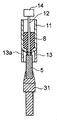
坩堝11の下方には、坩堝11の下端外周近傍と当接して該坩堝11を支持する、円筒形状のアフターヒータ13が配置される。アフターヒータ13は、坩堝と同様の材料より構成されており、坩堝11と同軸となるように配置されている。原材料加熱時において、該アフターヒータ13も高周波誘導によって発熱し、坩堝11の下端より漏洩する原材料融液を加熱可能としている。また、アフターヒータ13の長さは、ワークコイル17の長手方向において中央部に配置される坩堝11と該アフターヒータ13とを当接させて配置した際に、該ワークコイル17における有効加熱領域に該アフターヒータ13が収容されるように設定されている。該アフターヒータ13の設置により引下げ方向における均熱領域が拡大可能となり、結晶育成の条件をより広範なものとすることが可能となる。なお、引下げ操作時においては、シード5が原材料融液8に対して確実に接触し且つメニスカスが生成されることを確認した上で、結晶が好適に成長する速度にてシードが引下げられることが好ましい。このため、メニスカスの状態等が例えば後述するCCDカメラ等により撮影可能となるように、アフターヒータ13には円筒壁の一部を貫通する貫通窓13aが形成されている。
Below the
本発明においては、形状制御棒12に対して、上下動、回転、振動等、及びこれらの組み合わせからなる所定の動作をさせることにより、原材料融液8に対して坩堝貫通孔11bの開口部に向かうように送り込む付勢力を作用させる。原材料融液8は本来坩堝11の内面に対して濡れ性が低く、例えば坩堝11の内部空間から貫通孔11bに対して侵入することはない。特に形状制御棒12によって開口部の面積が狭められていることから、このような原材料融液11の漏出方向への移動はより困難となる。本発明の如く、形状制御棒12によって原材料融液8を強制的に貫通孔11bに向けて送り込むことにより、シードタッチに好適な原材料融液8の漏出状態を形成することが可能となる。
In the present invention, the
例えば、濡れ性の大きい原材料融液8の場合には、当該原材料融液8は形状制御棒12或いは坩堝の貫通孔11bを伝って容易に貫通孔11bの開口部から漏出する。このため、シード5の上端面(前述した接触面)の形状、配置に対する制限は大きくなく、極論すれば開口部直下に配置されていれば温度制御のみで好適なシードタッチを為すことも可能である。しかしながら、本発明が対象とするような濡れ性の小さな原材料融液8の場合、形状制御棒12によって開口部向けて送られた原材料融液8であっても、貫通孔11bの内壁等から受ける付勢力を超えるだけの自重量を有した量が開口部を超えない限り容易に坩堝11の外部に漏出しない。このため、シード5の上端面と瞬間的に漏出する原材料融液8とを接触させることが非常に難しくなる。本形態では、シード5の上端面を平坦面とし、貫通孔11bの開口部形成面を該平坦面に対して平行となるように個々の面を配置している。そして、シードタッチ時には、これら面を互いに当接させた状態とし、僅かの漏出量であってもシードタッチを行うことを可能としている。
For example, in the case of the
なお、この場合形状制御棒12が開口形成面から突き出す場合には、当該形状制御棒12がシード5に当接してシード5の位置を動かしてしまう等の事態が生じてしまう。このため、前述したように形状制御棒12の先端面は貫通孔11bの所謂出口側の開口形成面から突出しない範囲で動作することとしている。また、原材料融液8が過剰に漏出させられた場合、貫通孔11bの内壁面等から受ける付勢力によって当該領域の原材料融液8が開口部出口側に更に押し出されることも生じ得る。なお、この場合であっても、適当な引下げ速度等を設定することによって、原材料融液8の過剰供給を一時的なものとして適当な肉厚のパイプ状単結晶を得ることも可能である。このため、一時的に過剰に供給された原材料融液8がその場に維持可能となるように、シード5の上端面は開口部の開口広さよりも大きく設定されている。
In this case, when the
また、本実施形態において、坩堝貫通孔11bは、図1に示すように内側開口部から外側開口部にむけて形状及び大きさが一定とされた平行部を有している。形状制御棒12は中空状単結晶の中空部分を形成することを主たる目的としており、前述した所定の動作はこの平行部内で行われる必要がある。これは平行部よりも坩堝内部側で或いは内部側から所定の動作が為された場合、原材料融液8の送り込みの効果が大きい反面、中空部の制御が困難となることによる。また、前述したように、形状制御棒12の動作範囲は開口部から突出しないこととしているが、より詳細には、開口部から坩堝内側に移動した状態において、形状制御棒8表面−坩堝貫通部11b内壁に挟持されて厚さの規定をされた原材料融液8が、粘性によってその厚み変化させない量だけ、開口部端面から離れることとしても良い。以上より、形状制御棒8の所定の動作の範囲は、前述した平行部内で行われることが好ましい。
Further, in the present embodiment, the crucible through
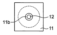
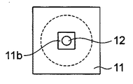
上述した実施形態では、坩堝貫通孔11bの延在軸に垂直な断面形状が円形であり、且つ形状制御棒12の軸方向に垂直な断面形状も円形である場合について述べている。このような実施形態における坩堝11等を軸方向下方から見た状態を図2Aに示す。当該形態は、形状制御棒12に対して回転動作を行う上で好適であり、且つ形状制御棒12と貫通孔11bの内壁との間隔が水平面内で全て均等であり、原材料融液8が貫通孔11bより均等に送り出されることが期待される。しかし、本発明は当該形態に限定されない。これらの変形例を図2B或いは図2Cを用いて具体的に示す。なお、これら図は図2Aと同様の様式で各部材を示すものであって、同一の構成は同一の参照符号を用いて説明している。図2Bに示す形態では、形状制御棒12の軸方向に垂直な断面形状を矩形状としている。また、図2Cに示す形態では、貫通孔11bの軸方向に垂直な断面形状を矩形状としている。これら構成の場合、場所により原材料融液8の漏出量に片寄りが生じる恐れがある。当該場合には、アフターヒータ13によって原材料融液8の粘性を低下させることで、好適なシードタッチを得ることが可能となる。なお、形状制御棒8表面−坩堝貫通部11b内壁の間隔について、本発明では図2B或いは図2Cのような例であっても、微視的な見地では定められた間隔を維持しているといえることから、これら例についても所定の間隔を空けていると定義することとする。
In the embodiment described above, the case where the cross-sectional shape perpendicular to the extending axis of the crucible through-
また、本実施形態では、形状制御棒12は坩堝11と同材質のものを用いている。当該組み合わせの場合、原材料融液8に対する形状制御棒12及び貫通孔11bの内壁の影響がほぼ等しくなる。その結果、円環状に漏出した際の内周側と外周側とでの原材料融液8の挙動が等しくなり、中空状のパイプ形状でのパイプ部の肉厚を所定の値に保つことが容易になるという効果が得られる。また、この効果は、形状制御棒12の表面状態が貫通孔11bの内壁の表面状態に近い状態に保たれた場合により顕著となる。しかし、例えば、形状制御棒12に対する原材料融液8の濡れ性を大きくするように、形状制御棒12の材質を定めても良い。例えばフッ化物系の単結晶を得ようとする場合この条件に合致する材料は限られてしまうが、当該組み合わせとすることで、原材料融液8の貫通孔11bに対する送り込みの効果がより高くなる可能性がある。また、同様の観点から、形状制御棒12の一部に攪拌用スクリューにおけるフライト等の攪拌翼を配置しても良い。このようなフライトを配することによって、原材料融液8を貫通孔11bに送り込む際の付勢力をより大きなものとすることが可能となる。
In this embodiment, the
次に、図1に示す構成からなる引下げ装置を用いて、実際に単結晶を育成する方法について説明する。図3A〜図3Eは、図1に示す引下げ装置において実際に単結晶の育成を行った場合について、各々の工程を段階的に示している。図3Aにおいて、坩堝11の内部には原材料7が固体状で装填されている。シード5はシード保持具31により上昇させられ、その上端面が坩堝貫通孔11bにおける開口部形成面と当接している。この状態でワークコイル17に対して高周波電力を印加し、原材料7の溶解を行う。原材料7が溶解されて原材料融液8となった状態を図3Bに示す。この状態では、原材料融液8と坩堝貫通孔11bの内壁即ち内表面との濡れ性のため、該貫通孔11bの内部まで原材料融液8は侵入していない。この状態から、制御棒駆動部14を動作させ、形状制御棒12の回転及び軸方向上下の動作を行わせる。この動作によって、具体的には形状制御棒12表面と原材料融液8との摩擦等の影響により、原材料融液8は貫通孔11bと形状制御棒12とによって構成される円筒状空間に送り込まれる。この状態を図3Cに示す。
Next, a method of actually growing a single crystal using the pulling apparatus having the configuration shown in FIG. 1 will be described. 3A to 3E show the respective steps step by step when a single crystal is actually grown in the pulling apparatus shown in FIG. In FIG. 3A, the
シード保持具31によりシード5を僅かに下方に引下げ、原材料融液8がシード5の上面に接触した部分においてメニスカスが形成されているか否かを、貫通窓13aを介して確認する。この状態を図3Dに示す。なお、本形態では目視によりメニスカスの形成を確認しているが、予め現時点での保持温度における、形状制御棒12の動作時間と原材料融液8の漏出量との関係を得ておき、当該関係に基づいて時間によりシードの引下げタイミングを設定することとしても良い。メニスカス形成後、図3Eに示すようにシードの引下げを実施し、シート5より連続的に成長する中空状単結晶9を育成する。このように、形状制御棒12によって原材料融液8を貫通孔11bへ送り込む作用を得ることにより、適切なシードタッチが困難である濡れ性の小さな原材料融液8を用いての中空状単結晶の育成が可能となる。
The
次に、図1に示した構成を含む単結晶引下げ装置の概略構成について説明する。図4は、本発明の一実施形態に係る単結晶引下げ装置を側方から見た状態での概略構成を示している。単結晶引下げ装置1は、前述したように、主たる構成として、シード5、坩堝11、アフターヒータ13、ワークコイル17、形状制御棒12、制御棒駆動部14、及びシード保持具31、更には、坩堝ステージ19、アウターチューブ25、シード駆動機構33、CCDカメラ35、及び制御装置39を有している。アフターヒータ13は、その下端において円環状の坩堝ステージ19の上面によって支持されている。坩堝ステージ19は、セラミックス、石英等、加熱に用いる高周波誘導に対して絶縁性を有する材料から構成されている。坩堝ステージ19は、下面において、該坩堝ステージ19と同様の材料からなる円筒状のアウターチューブ25の上端部によって支持されている。これら坩堝11、アフターヒータ13、坩堝ステージ19及びアウターチューブ25は、同軸となるように配置されており、結晶の引下げ操作は該軸に沿って行われる。
Next, a schematic configuration of the single crystal pulling apparatus including the configuration shown in FIG. 1 will be described. FIG. 4 shows a schematic configuration of a single crystal pulling apparatus according to an embodiment of the present invention as viewed from the side. As described above, the single
また、シード5はシード保持具31の上部端部によって保持されており、棒状のシード保持具31はその下端においてシード駆動機構33と接続される。シード5は、このシード駆動機構33によるシード保持具31の軸方向の上下動に応じて上下動可能とされている。CCDカメラ35は、メニスカスの形成状態を観察するために用いられる。前述したように、アフターヒータ13にはメニスカス観察用の貫通窓13aが設けられており、CCDカメラ35は当該貫通窓を介してメニスカス形成領域の映像を撮像することが可能となっている。CCDカメラ35から得られた映像は制御装置39に送信され、得られた映像に基づいてメニスカスの状態の判別が行われ、当該判別結果に応じてシード5の引下げ速度の制御が行われる。即ち、メニスカス映像に応じてシード駆動装置33の制御が為され、シード5の上昇動作の減速、停止、或いは降下への変更、降下速度の調整等の動作が実施される。また、同様に、メニスカスの状態に応じて形状制御棒12の動作の継続時間或いはその大きさ等も制御される。
The
なお、上述した結晶育成ユニット3で述べた構成は一例であり、例えば原材料に応じて種々改変が可能である。具体的には、坩堝11とワークコイル17との間に更なる発熱体となる導電性材料からなる円筒状の部材を配しても良い。また、坩堝11自体が発熱する構成ではなく、この円筒状の部材が発熱する構成としても良い。或いは、アフターヒータをなくする構成とする、アフターヒータを二重構造とする、アフターヒータとワークコイル17との位置関係を改変可能とする、等の構造とすることも可能である。また、単結晶の引下げは、例えば不活性ガス雰囲気、或いは酸化性、フッ化性等ガス雰囲気等、特定の気体雰囲気中において行われることが好ましい。従って、引下げ装置1は密閉可能なチャンバの内部に設置され、排気系及びガス導入系を該チャンバに付随させて、内部空間を所謂真空状態まで排気する、或いは特定のガスで所定の圧力を維持すること等を可能としておくことが好ましい。
The configuration described in the crystal growth unit 3 described above is an example, and various modifications can be made depending on the raw material, for example. Specifically, a cylindrical member made of a conductive material serving as a further heating element may be disposed between the
本発明においては、中空状単結晶の育成に際して、中空部の内径を規定する形状制御棒12に対して原材料融液8を坩堝貫通孔11b(厳密には形状制御棒8表面−坩堝貫通部11b内壁の間)に送り込む作用を付加させている。以上述べたように、本発明によれば、当該形状制御棒12の付加的作用により、本来中空状単結晶の育成が困難であった濡れ性の劣る原材料融液を用いた場合であっても、好適にシードタッチを実施し、肉厚の均一性に優れ且つ各部分における組成等の均一性に優れた高品位な中空状の単結晶を育成することが可能となる。
In the present invention, when growing the hollow single crystal, the
上述したように、本発明は坩堝貫通孔内壁との濡れ性に劣る原材料融液と用いて中空状の単結晶を育成する上で好適である。しかし、本発明は当該組み合わせにのみならず、例えば坩堝貫通孔内壁に対して原材料融液の濡れ性が大きい場合に用いても良い。この場合、原材料融液の保持温度を低めに保ち粘性を高く維持することが好ましい。当該条件において形状制御棒を適度に動作させることにより、原材料融液を安定的にシードに対して接触させることが可能となり、単結晶の成長の初期状態から形状的に優れた単結晶が得られる。また、坩堝内部の原材料融液に対する攪拌効果が得られることから、得られる単結晶の各部において、均質性に優れた単結晶が得られる。 As described above, the present invention is suitable for growing a hollow single crystal using a raw material melt having poor wettability with the inner wall of the crucible through hole. However, the present invention is not limited to this combination, and may be used, for example, when the wettability of the raw material melt is large with respect to the inner wall of the crucible through hole. In this case, it is preferable to maintain a high viscosity by keeping the raw material melt holding temperature low. By appropriately operating the shape control rod under these conditions, the raw material melt can be stably brought into contact with the seed, and a single crystal excellent in shape can be obtained from the initial state of single crystal growth. . Moreover, since the stirring effect with respect to the raw material melt inside a crucible is acquired, the single crystal excellent in the homogeneity is obtained in each part of the obtained single crystal.
1:引下げ装置、 5:シード、 7:原材料、 8:原材料融液、 9:単結晶、11:坩堝、 11b:坩堝貫通孔、 12:形状制御棒、 13:アフターヒータ、 13a貫通窓、 14:制御棒駆動部、 17:ワークコイル、 19:坩堝ステージ、 25:アウターチューブ、 31:シード保持具、 33:シード駆動機構、 35:CCDカメラ、 39:制御装置 1: Pulling device, 5: Seed, 7: Raw material, 8: Raw material melt, 9: Single crystal, 11: Crucible, 11b: Crucible through hole, 12: Shape control rod, 13: After heater, 13a through window, 14 : Control rod drive unit, 17: work coil, 19: crucible stage, 25: outer tube, 31: seed holder, 33: seed drive mechanism, 35: CCD camera, 39: control device
Claims (10)
前記貫通孔の開口部が形成される前記坩堝における開口部の形成面に対して前記シードにおける前記原材料融液との接触面を接触させ、
前記貫通孔に棒状の形状制御棒の先端部を挿入した状態で、前記坩堝の内部に保持された原材料を溶融して前記原材料融液を生成し、
前記形状制御棒に所定の動作を実施させて前記原材料融液を前記貫通孔に送り込み、
前記貫通孔に送り込まれた前記原材料融液を前記シードの前記接触面に接触させ、
前記シードを前記所定の引下げ軸に沿って引下げることを特徴とする単結晶の引下げ方法。 Leakage of raw material melt held in the crucible having a cylindrical shape that becomes a closed portion with a closed bottom portion, and having a through hole that penetrates the closed portion from the inside of the cylindrical shape to the outside from the through hole The seed that determines the crystal orientation when the raw material melt is crystallized is brought into contact with the leaked raw material melt, and the seed is pulled down along a predetermined pulling axis to grow the seed as a base point. A method of pulling down a single crystal to obtain a crystal,
Contacting the contact surface with the raw material melt in the seed against the formation surface of the opening in the crucible in which the opening of the through hole is formed;
In a state where the tip of the rod-shaped shape control rod is inserted into the through hole, the raw material held in the crucible is melted to generate the raw material melt,
Causing the shape control rod to perform a predetermined operation to feed the raw material melt into the through-hole,
Bringing the raw material melt fed into the through hole into contact with the contact surface of the seed;
A method of pulling down a single crystal, wherein the seed is pulled down along the predetermined pulling axis.
前記坩堝と前記所定の引下げ軸について同軸であって、先端部外周が前記貫通孔の内壁に対して所定の間隔を空けて挿通可能な形状制御棒と、
前記形状制御棒に所定の動作を行わせる制御棒駆動部と、を有することを特徴とする単結晶の引下げ装置。 Leakage of raw material melt held in the crucible having a cylindrical shape that becomes a closed portion with a closed bottom portion, and having a through hole that penetrates the closed portion from the inside of the cylindrical shape to the outside from the through hole The seed that determines the crystal orientation when the raw material melt is crystallized is brought into contact with the leaked raw material melt, and the seed is pulled down along a predetermined pulling axis to grow the seed as a base point. A single crystal pulling device for obtaining a crystal,
A shape control rod that is coaxial with the crucible and the predetermined pull-down shaft, and whose tip outer periphery can be inserted with a predetermined distance from the inner wall of the through-hole,
And a control rod driving unit that causes the shape control rod to perform a predetermined operation.
Priority Applications (1)
| Application Number | Priority Date | Filing Date | Title |
|---|---|---|---|
| JP2009095404A JP4844772B2 (en) | 2009-04-10 | 2009-04-10 | Single crystal pulling method |
Applications Claiming Priority (1)
| Application Number | Priority Date | Filing Date | Title |
|---|---|---|---|
| JP2009095404A JP4844772B2 (en) | 2009-04-10 | 2009-04-10 | Single crystal pulling method |
Publications (2)
| Publication Number | Publication Date |
|---|---|
| JP2010241663A true JP2010241663A (en) | 2010-10-28 |
| JP4844772B2 JP4844772B2 (en) | 2011-12-28 |
Family
ID=43095122
Family Applications (1)
| Application Number | Title | Priority Date | Filing Date |
|---|---|---|---|
| JP2009095404A Expired - Fee Related JP4844772B2 (en) | 2009-04-10 | 2009-04-10 | Single crystal pulling method |
Country Status (1)
| Country | Link |
|---|---|
| JP (1) | JP4844772B2 (en) |
Cited By (1)
| Publication number | Priority date | Publication date | Assignee | Title |
|---|---|---|---|---|
| WO2015146932A1 (en) * | 2014-03-28 | 2015-10-01 | 田中貴金属工業株式会社 | Metal wire rod composed of iridium or iridium alloy |
Citations (5)
| Publication number | Priority date | Publication date | Assignee | Title |
|---|---|---|---|---|
| JPS4812669B1 (en) * | 1968-08-16 | 1973-04-21 | ||
| JPS62246894A (en) * | 1986-04-15 | 1987-10-28 | Kyushu Denshi Kinzoku Kk | Method and apparatus for producing single crystal |
| JPH04280891A (en) * | 1991-03-08 | 1992-10-06 | Agency Of Ind Science & Technol | Method for growing single crystal fiber |
| JP2001131000A (en) * | 1999-10-29 | 2001-05-15 | Kyocera Corp | Fibrous single crystal and method for producing the same |
| JP2009035434A (en) * | 2007-07-31 | 2009-02-19 | Nec Tokin Corp | Method of single crystal growth |
-
2009
- 2009-04-10 JP JP2009095404A patent/JP4844772B2/en not_active Expired - Fee Related
Patent Citations (5)
| Publication number | Priority date | Publication date | Assignee | Title |
|---|---|---|---|---|
| JPS4812669B1 (en) * | 1968-08-16 | 1973-04-21 | ||
| JPS62246894A (en) * | 1986-04-15 | 1987-10-28 | Kyushu Denshi Kinzoku Kk | Method and apparatus for producing single crystal |
| JPH04280891A (en) * | 1991-03-08 | 1992-10-06 | Agency Of Ind Science & Technol | Method for growing single crystal fiber |
| JP2001131000A (en) * | 1999-10-29 | 2001-05-15 | Kyocera Corp | Fibrous single crystal and method for producing the same |
| JP2009035434A (en) * | 2007-07-31 | 2009-02-19 | Nec Tokin Corp | Method of single crystal growth |
Cited By (3)
| Publication number | Priority date | Publication date | Assignee | Title |
|---|---|---|---|---|
| WO2015146932A1 (en) * | 2014-03-28 | 2015-10-01 | 田中貴金属工業株式会社 | Metal wire rod composed of iridium or iridium alloy |
| JP2015190012A (en) * | 2014-03-28 | 2015-11-02 | 田中貴金属工業株式会社 | Metal wire made of iridium or iridium alloy |
| US10137496B2 (en) | 2014-03-28 | 2018-11-27 | Tanaka Kikinzoku Kogyo K.K. | Metal wire rod composed of iridium or iridium alloy |
Also Published As
| Publication number | Publication date |
|---|---|
| JP4844772B2 (en) | 2011-12-28 |
Similar Documents
| Publication | Publication Date | Title |
|---|---|---|
| JP6471492B2 (en) | Single crystal manufacturing method | |
| JPH09286692A (en) | Apparatus for producing semiconductor single crystal and production of semiconductor single crystal | |
| US20130263772A1 (en) | Method and apparatus for controlling melt temperature in a Czochralski grower | |
| JP4844772B2 (en) | Single crystal pulling method | |
| JP5176915B2 (en) | Method for growing silicon single crystal | |
| JP3992469B2 (en) | Oxide eutectic bulk production equipment and production method | |
| US20170370018A1 (en) | Method for producing crystal | |
| JP2008214118A (en) | Method for manufacturing semiconductor single crystal | |
| JP2016088820A (en) | Single crystal manufacturing method and single crystal manufacturing apparatus | |
| JP4844771B2 (en) | Single crystal pulling method, crucible and pulling apparatus used in the method | |
| JP4793604B2 (en) | Single crystal pulling method and pulling apparatus | |
| JP4807669B2 (en) | Raw material supply device for pulling device | |
| JP5051179B2 (en) | Method for producing single crystal using temperature gradient furnace | |
| US20180016703A1 (en) | Method for producing crystal | |
| JP4916425B2 (en) | Crystal growth method and apparatus | |
| JP5195301B2 (en) | Single crystal pulling device | |
| CN212533193U (en) | Cooling device and crystal pulling system | |
| JP4793605B2 (en) | Single crystal pulling device | |
| JP4191704B2 (en) | Pulling device | |
| JP5282801B2 (en) | Single crystal manufacturing apparatus and manufacturing method | |
| KR100304291B1 (en) | Silicon crystal and its manufacturing apparatus, manufacturing method | |
| JP2025117662A (en) | Crystal Growth Equipment | |
| JP6922870B2 (en) | Method for manufacturing silicon single crystal | |
| JP2017193469A (en) | After heater and sapphire single crystal manufacturing equipment | |
| JP6400946B2 (en) | Method for producing Si-Ge solid solution single crystal |
Legal Events
| Date | Code | Title | Description |
|---|---|---|---|
| A977 | Report on retrieval |
Free format text: JAPANESE INTERMEDIATE CODE: A971007 Effective date: 20110623 |
|
| A131 | Notification of reasons for refusal |
Free format text: JAPANESE INTERMEDIATE CODE: A131 Effective date: 20110629 |
|
| A521 | Request for written amendment filed |
Free format text: JAPANESE INTERMEDIATE CODE: A523 Effective date: 20110825 |
|
| TRDD | Decision of grant or rejection written | ||
| A01 | Written decision to grant a patent or to grant a registration (utility model) |
Free format text: JAPANESE INTERMEDIATE CODE: A01 Effective date: 20110914 |
|
| A01 | Written decision to grant a patent or to grant a registration (utility model) |
Free format text: JAPANESE INTERMEDIATE CODE: A01 |
|
| A61 | First payment of annual fees (during grant procedure) |
Free format text: JAPANESE INTERMEDIATE CODE: A61 Effective date: 20110927 |
|
| FPAY | Renewal fee payment (event date is renewal date of database) |
Free format text: PAYMENT UNTIL: 20141021 Year of fee payment: 3 |
|
| R150 | Certificate of patent or registration of utility model |
Ref document number: 4844772 Country of ref document: JP Free format text: JAPANESE INTERMEDIATE CODE: R150 Free format text: JAPANESE INTERMEDIATE CODE: R150 |
|
| LAPS | Cancellation because of no payment of annual fees |