JP2010237205A - Self-calibrated interrogation system for photo-sensor - Google Patents
Self-calibrated interrogation system for photo-sensor Download PDFInfo
- Publication number
- JP2010237205A JP2010237205A JP2010071272A JP2010071272A JP2010237205A JP 2010237205 A JP2010237205 A JP 2010237205A JP 2010071272 A JP2010071272 A JP 2010071272A JP 2010071272 A JP2010071272 A JP 2010071272A JP 2010237205 A JP2010237205 A JP 2010237205A
- Authority
- JP
- Japan
- Prior art keywords
- signal
- optical
- pressure sensor
- reflected
- photodetector
- Prior art date
- Legal status (The legal status is an assumption and is not a legal conclusion. Google has not performed a legal analysis and makes no representation as to the accuracy of the status listed.)
- Pending
Links
Images


Classifications
-
- G—PHYSICS
- G01—MEASURING; TESTING
- G01L—MEASURING FORCE, STRESS, TORQUE, WORK, MECHANICAL POWER, MECHANICAL EFFICIENCY, OR FLUID PRESSURE
- G01L9/00—Measuring steady of quasi-steady pressure of fluid or fluent solid material by electric or magnetic pressure-sensitive elements; Transmitting or indicating the displacement of mechanical pressure-sensitive elements, used to measure the steady or quasi-steady pressure of a fluid or fluent solid material, by electric or magnetic means
- G01L9/0041—Transmitting or indicating the displacement of flexible diaphragms
- G01L9/0076—Transmitting or indicating the displacement of flexible diaphragms using photoelectric means
- G01L9/0077—Transmitting or indicating the displacement of flexible diaphragms using photoelectric means for measuring reflected light
- G01L9/0079—Transmitting or indicating the displacement of flexible diaphragms using photoelectric means for measuring reflected light with Fabry-Perot arrangements
Abstract
Description
本発明は全般的には光センサに関し、またさらに詳細には広いバンド幅レンジにわたって高温で静圧及び動圧を計測するためのファブリ・ペロー型光学式圧力センサに関する問合わせ(interrogation)方法に関する。 The present invention relates generally to optical sensors, and more particularly to an interrogation method for a Fabry-Perot optical pressure sensor for measuring static and dynamic pressures at high temperatures over a wide bandwidth range.
圧力センサは工業用途及び民生用途の広い範囲で使用されている。ブルドン管型圧力センサ、ダイアフラム式圧力センサ及びシリコン又はSOI(silicon on insulator)式ピエゾ抵抗圧力センサなど様々なタイプの圧力センサを用いて、大きさが多様に異なる圧力を計測することができる。ダイアフラム式圧力センサの幾つかの変形形態は、カンチレバー式圧力センサ、光学読み取り式圧力センサなどによって様々な範囲の圧力の計測に利用されてきた。 Pressure sensors are used in a wide range of industrial and consumer applications. Various types of pressure sensors such as a Bourdon tube type pressure sensor, a diaphragm type pressure sensor, and a silicon or SOI (silicon on insulator) type piezoresistive pressure sensor can be used to measure pressures having various sizes. Several variations of diaphragm pressure sensors have been used to measure pressures in various ranges by cantilever pressure sensors, optically read pressure sensors, and the like.
ファブリ・ペローキャビティを利用した光ファイバセンサはその高い感度のゆえに、温度、歪み、圧力及び変位の計測にとって魅力的であることが実証されている。従来の電気式センサに対する光ファイバセンサの利点の幾つかには、電磁気的干渉(EMI)に対する耐性、過酷な環境に対する抵抗性、形状因子(form factor)の低減、並びに多重化の可能性が含まれる。 Fiber optic sensors utilizing Fabry-Perot cavities have proven attractive for temperature, strain, pressure and displacement measurements due to their high sensitivity. Some of the advantages of fiber optic sensors over traditional electrical sensors include resistance to electromagnetic interference (EMI), resistance to harsh environments, reduced form factor, and the possibility of multiplexing. It is.
幾つかの例ではファブリ・ペローキャビティは圧力を受けて屈曲するダイアフラムによって形成される。このキャビティは可視光源又は赤外光源によって照射されており、この光は様々な量でダイアフラムによる反射及びダイアフラムの透過の両方を生じる。この光が光源に向かって戻るように反射されると、この光がファブリ・ペローキャビティの長さに関する入射ビーム特性とで強め合うかつ/又は弱め合う干渉が生じる。加えられる圧力、力、応力又は歪みなど計測しようとする量(本明細書では、計測量と呼ぶ)の結果としてダイアフラムが屈曲したとき、ファブリ・ペローキャビティの長さが変化するためにその干渉挙動が変化する。 In some examples, the Fabry-Perot cavity is formed by a diaphragm that bends under pressure. The cavity is illuminated by a visible light source or an infrared light source, and this light causes both diaphragm reflection and diaphragm transmission in varying amounts. When this light is reflected back towards the light source, there is interference that builds up and / or weakens with the incident beam characteristics with respect to the length of the Fabry-Perot cavity. When the diaphragm is bent as a result of the amount to be measured, such as applied pressure, force, stress, or strain (referred to herein as the measured amount), the length of the Fabry-Perot cavity changes, causing its interference behavior Changes.
ダイアフラム屈曲を使用可能な線形出力に変換する際の主要な問題点としては、センサ自体のゆらぎ以外のあらゆるゆらぎにシステムが影響されないようにしながら受信器におけるノイズを克服するように適当な光信号レベルを維持することを含む。典型的なゆらぎには、問合わせ用光源の強度ゆらぎ、光学経路内部にある機械的ゆらぎ、システム内の温度誘導性ゆらぎが含まれる可能性がある。 The main problem in converting diaphragm bending to a usable linear output is that the optical signal level is adequate to overcome the noise at the receiver while keeping the system unaffected by any fluctuations other than the fluctuations of the sensor itself. Including maintaining. Typical fluctuations can include intensity fluctuations in the interrogation light source, mechanical fluctuations within the optical path, and temperature induced fluctuations in the system.
本発明の例示的な一実施形態では、光学式圧力センサ問合わせシステムを提供する。本システムは、光学式圧力センサに光信号を提供するための光源と、該光学式圧力センサから反射された信号を受け取るための光結合器と、を含む。この光結合器はさらに、反射された信号を分割し、この反射信号の第1の部分を第1の光検出器に提供する。本システムはさらに、反射信号の第2の部分信号を受け取りフィルタ処理した信号を第2の光検出器に提供するためのフィルタと、第1及び第2の光検出器出力信号の光強度に関する除算又は減算に基づいて圧力を取得するように構成された処理回路と、を含む。この処理回路はさらに、光信号の波長を制御するために光源に対してフィードバック信号を提供するように構成される。 In an exemplary embodiment of the invention, an optical pressure sensor query system is provided. The system includes a light source for providing an optical signal to the optical pressure sensor and an optical coupler for receiving a signal reflected from the optical pressure sensor. The optocoupler further splits the reflected signal and provides a first portion of the reflected signal to the first photodetector. The system further includes a filter for receiving a second partial signal of the reflected signal and providing a filtered signal to the second photodetector and a division of the first and second photodetector output signals with respect to the light intensity. Or a processing circuit configured to obtain a pressure based on the subtraction. The processing circuit is further configured to provide a feedback signal to the light source to control the wavelength of the optical signal.
本発明の別の例示的実施形態では、別の光学式圧力センサ問合わせシステムを提供する。本システムは、光学式圧力センサに光信号を提供するための光源と、該光学式圧力センサから反射された信号を受け取るための光結合器と、を含む。この光結合器はさらに、反射された信号を分割すると共に、反射信号の第1の部分を高域通過フィルタに提供しかつ反射信号の第2の部分を低域通過フィルタに提供する。本システムはさらに、高域通過フィルタから第1のフィルタ処理済み信号を受け取りフィルタ処理済み信号を第2の光検出器に提供するための第1の光検出器と、低域通過フィルタから第2のフィルタ処理済み信号を受け取るための第2の光検出器と、該第1及び第2の光検出器出力信号の光強度同士の関係に基づいて圧力を取得するように構成された処理回路と、を含む。 In another exemplary embodiment of the present invention, another optical pressure sensor interrogation system is provided. The system includes a light source for providing an optical signal to the optical pressure sensor and an optical coupler for receiving a signal reflected from the optical pressure sensor. The optocoupler further splits the reflected signal and provides a first portion of the reflected signal to the high pass filter and a second portion of the reflected signal to the low pass filter. The system further includes a first photodetector for receiving a first filtered signal from the high pass filter and providing the filtered signal to the second photodetector, and a second from the low pass filter. A second photodetector for receiving the filtered signal and a processing circuit configured to obtain pressure based on a relationship between the light intensities of the first and second photodetector output signals; ,including.
本発明の例示的な一実施形態では、光学式圧力センサ問合わせシステムを提供する。本システムは、光学式圧力センサに光信号を提供するための光源と、該光学式圧力センサから反射された信号を受け取るための3ポートフィルタと、を含む。この光結合器はさらに、反射された信号を分割しこの反射信号の低域通過フィルタ処理済み信号を第1の光検出器に提供する。本システムはさらに、3ポートフィルタから反射信号の高域通過フィルタ処理済み信号を受け取るための第2の光検出器と、該第1及び第2の光検出器出力信号の光強度同士の関係に基づいて圧力を取得するように構成された処理回路と、を含む。 In an exemplary embodiment of the invention, an optical pressure sensor query system is provided. The system includes a light source for providing an optical signal to the optical pressure sensor and a three-port filter for receiving a signal reflected from the optical pressure sensor. The optocoupler further splits the reflected signal and provides a low pass filtered signal of the reflected signal to the first photodetector. The system further includes a second photodetector for receiving a high-pass filtered signal of the reflected signal from the three-port filter and a relationship between the light intensities of the first and second photodetector output signals. And a processing circuit configured to obtain a pressure based thereon.
本発明の別の例示的実施形態では、光学式圧力センサ問合わせシステムを提供する。本システムは、第1の光信号及び第2の光信号を提供するための第1の光源及び第2の光源と、該第1及び第2の光信号を受け取りかつ光学式圧力センサに結合させた信号を提供するための第1の光結合器と、を含む。本システムはさらに、該光学式圧力センサから反射された信号を受け取り、該反射信号を分割し、該反射信号の第1の部分を第1の光検出器に提供しかつ該反射信号の第2の部分を第2の光検出器に提供するための第2の光結合器を含む。本システムはさらに、該第1及び第2の光検出器出力信号の光強度同士の関係に基づいて圧力を取得するように構成された処理回路を含む。この処理回路はさらに、第1及び第2の光信号の波長を制御するために第1及び第2の光源にフィードバック信号を提供するように構成される。 In another exemplary embodiment of the present invention, an optical pressure sensor query system is provided. The system includes a first light source and a second light source for providing a first optical signal and a second optical signal, and receiving and coupling the first and second optical signals to an optical pressure sensor. And a first optical coupler for providing a received signal. The system further receives a signal reflected from the optical pressure sensor, splits the reflected signal, provides a first portion of the reflected signal to a first photodetector and a second of the reflected signal. A second optical coupler for providing the second optical detector to the second photodetector. The system further includes a processing circuit configured to obtain pressure based on the relationship between the light intensities of the first and second photodetector output signals. The processing circuit is further configured to provide feedback signals to the first and second light sources to control the wavelengths of the first and second optical signals.
本発明のさらに別の例示的実施形態では、光学式圧力センサを問合わせる方法を提供する。本方法は、光学式圧力センサに光信号を提供する工程と、該光学式圧力センサから反射された信号を第1の信号と第2の信号に分割する工程と、を含む。本方法はさらに、第1及び第2の光検出器出力信号の光強度同士の減算に基づいて圧力を取得するためにフィルタ処理した第1の信号と第2の信号とを解析する工程を含む。 In yet another exemplary embodiment of the present invention, a method for interrogating an optical pressure sensor is provided. The method includes providing an optical signal to the optical pressure sensor and dividing the signal reflected from the optical pressure sensor into a first signal and a second signal. The method further includes analyzing the filtered first and second signals to obtain pressure based on the subtraction between the light intensities of the first and second photodetector output signals. .
本発明に関するこれらの特徴、態様及び利点、並びにその他の特徴、態様及び利点については、同じ参照符号が図面全体を通じて同じ部分を表している添付の図面を参照しながら以下の詳細な説明を読むことによってより理解が深まるであろう。 For these features, aspects and advantages of the present invention, as well as other features, aspects and advantages, read the following detailed description with reference to the accompanying drawings, wherein like reference numerals represent like parts throughout the drawings. Will deepen your understanding.
本明細書において詳細に検討するように、本発明の実施形態は、外部型ファブリ・ペロー干渉計(EFPI)の原理に基づいた高温光センサ向けの問合わせ方法を含む。 As discussed in detail herein, embodiments of the present invention include an interrogation method for high temperature light sensors based on the principle of an external Fabry-Perot interferometer (EFPI).
一実施形態におけるこれに対処するための方式は同相モード(common-mode)システムノイズを減算除去するような差分式技法を使用することである。LEDなどの光源や薄膜フィルタなどの構成要素が低コストで利用可能であるため、周波数(又は、波長)領域における差分式技法は特に魅力的である。この領域ではその膜の動きが、圧力と共にその波長応答が変動するような可変の光学フィルタのようにそのセンサを振る舞わせる。適当な低コストの問合わせ器アーキテクチャは、この応答を線形振幅応答に変換することが可能である。 The approach to address this in one embodiment is to use a differential technique that subtracts out common-mode system noise. The differential technique in the frequency (or wavelength) domain is particularly attractive because light sources such as LEDs and components such as thin film filters are available at low cost. In this region, the movement of the film makes the sensor behave like a variable optical filter whose wavelength response varies with pressure. A suitable low cost interrogator architecture can convert this response to a linear magnitude response.
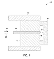
図1はEFPI式圧力センサ10の斜視図である。光ファイバ12はフェルール14の内部で固定される。光ファイバ−フェルール構造の一方の側面16は、標準のファイバ研磨処理を用いて磨かれる。この研磨によって、サブストレート20を装着するための平らな表面が保証される。この光ファイバ−フェルール構造を外側金属ケーシング18が囲繞している。ダイアフラムの役割をするサブストレート20は、キャビティギャップ内に真空をトラップするように真空接合(vacuum bonding)処理を通じて光ファイバ−フェルール構造の表面16に取り付けられる。一実施形態ではその真空接合処理には、レーザー融解処理や表面活性化接合処理が含まれる。一実施形態ではそのサブストレート20に使用する材料は、シリコン、ガラス、石英、又はサファイアを含む。ファブリ・ペローキャビティ24がサブストレート20内に規定されており、これがさらにダイアフラムの外径を規定している。一実施形態では、サブストレート20のうちファブリ・ペローキャビティの半分を規定している内側表面は反射性の薄い金属薄膜(図示せず)でコーティングされることがある。一実施形態ではその金属薄膜に使用する材料は、白金、金、チタン、クロム、銀あるいは高温対応の別の任意の金属を含む。
FIG. 1 is a perspective view of an
ファイバ12の中に入射光信号26を通過させ、これがキャビティギャップ24を通ってサブストレート20に伝えられる。一実施形態では、その光信号を発光ダイオード(LED)によって発生させることがある。光信号26はサブストレート20で反射され、反射信号28としてファイバ12内に戻される。図1の矢印の方向で光の伝播を示している。反射された光は光検出器(図示せず)によって検出され、この光検出器においてキャビティギャップ24の距離計測値を生成するように信号が復調される。キャビティギャップ24はダイアフラムの上に加えられた圧力によって変化するため、当該距離に関する復調信号によって圧力が決定される。
An incident optical signal 26 is passed through the
図2は、図1に示した圧力センサなどの圧力センサ42に関する問合わせシステム40の全体を表した概要図である。発光ダイオード(LED)44によって光信号46を発生させると共に、この光信号46を光ファイバ48によって光結合器47に送っている。光結合器47はそのビームをセンサ42に送る。一実施形態ではそのLEDの中心波長は1550nmである。光学式圧力センサ42から反射された信号50は、光学式問合わせ器検出器システム52に対してその信号を分割している光結合器47を通って戻される。検出器回路52は、反射信号50を2つの等しい信号(第1の信号56と第2の信号58)に分割している光結合器54を含む。第1の信号56はブロードバンド信号を検出する第1の光検出器60に直接渡される。第2の信号58はナローバンドフィルタ64を通り、ナローバンド信号を検出する第2の光検出器62に渡される。一実施形態ではその光検出器62及び60はフォトダイオードである。光検出器60及び62の出力信号66及び68は次いで、圧力信号を出力するように処理回路70によって解析される。処理回路64は、プロセッサ、メモリ、及び付属の回路(例えば、コンピュータシステム)を含むことがある。
FIG. 2 is a schematic diagram showing the
センサ42が3つの材料からなるスタックで構成されると仮定すると、その反射率はセンサ42からの波長λの関数として次式で与えられる。
Assuming that

その光源が離散的な波長(レーザーなど)になく連続した波長を成す(LEDやSLEDなど)ような実施形態では、センサ42から出力される光強度Iは次式で与えられる。
In an embodiment where the light source has a continuous wavelength (such as an LED or SLED) rather than a discrete wavelength (such as a laser), the light intensity I output from the
式中、G(λ)は光源のスペクトル出力密度分布であり、f(λ)は受信器内のインラインフィルタの応答である。光検出器と一緒に使用されるフィルタが存在しないような場合には、その第1の信号56は「ブロードバンド」信号であると共に、f(λ)=1である。他方、光検出器62の波長応答を狭めるためにスペクトルフィルタ64が使用される場合には、その第2の信号58は「ナローバンド」信号となる。上記の式において、スペクトル出力密度分布G(λ)は概ね次式で与えられる。
Where G (λ) is the spectral output density distribution of the light source and f (λ) is the response of the inline filter in the receiver. In the absence of a filter used with the photodetector, the
式中、λ0はLEDの中心波長である。ブロードバンド問合わせの場合には、応答の縞構造は、ギャップが大きくなるに連れて消失する、すなわち「ウォッシュアウト(wash out)される」傾向がある。縞が消失する箇所であるギャップは、光源のバンド幅に依存するが、可視光や近赤外光の典型的なLEDでは、応答の縞構造を有意にウォッシュアウトさせるには約10〜15の縞からなるギャップで十分となり得る。 Where λ 0 is the center wavelength of the LED. In the case of broadband inquiries, the fringe structure of the response tends to disappear, i.e. "wash out" as the gap grows. The gap, where the fringes disappear, depends on the bandwidth of the light source, but for a typical LED for visible or near infrared light, about 10 to 15 is required to significantly wash out the response fringe structure. A gap of stripes may be sufficient.
ブロードバンド問合わせのレファレンスとしての使用に基づく典型的なファブリ・ペローセンサは、縞応答を「ウォッシュアウト」させるのに十分な大きさのキャビティ深度を利用している。しかし本考案の一実施形態ではそのセンサは、その深度が5縞未満など非常に小さいキャビティギャップで動作するように設計することができる。別の実施形態のセンサは深度が3縞未満で動作しており、またさらに別の実施形態のセンサは深度が2縞未満で動作している。一例ではそのセンサ素子上のギャップは、強度−キャビティ深度曲線上でその素子を動作させる位置を正確に制御する目的でギャップの厚さを正確に制御するために半導体処理技法によってウェハ規模で製作される。ギャップを小さくする程、それだけキャビティ深度の絶対誤差が小さくなりかつ強度対ギャップの伝達関数上での位置の不確定度が小さくなる。キャビティギャップに関するこの正確な「デッドレコニング(dead reckoning)」によって、極めて望ましくない製作後のトリミングやチューニングを回避することができる。 A typical Fabry-Perot sensor based on use as a broadband query reference utilizes a cavity depth that is large enough to “wash out” the fringe response. However, in one embodiment of the present invention, the sensor can be designed to operate with a very small cavity gap, such as less than 5 stripes in depth. Another embodiment of the sensor is operating at a depth of less than 3 stripes, and yet another embodiment of the sensor is operating at a depth of less than 2 stripes. In one example, the gap on the sensor element is fabricated on a wafer scale by semiconductor processing techniques to accurately control the gap thickness for the purpose of accurately controlling the position at which the element is operated on the intensity-cavity depth curve. The The smaller the gap, the smaller the absolute error of the cavity depth and the less uncertainty of position on the strength versus gap transfer function. This precise “dead reckoning” with respect to the cavity gap avoids highly undesirable post-production trimming and tuning.
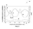
一実施形態では、検出器回路52のナローバンド信号から出力される光強度(強度I1を生成)とブロードバンド信号から出力される光強度(光強度I2を生成)との比を用いて圧力を取得すると共に同相モード信号の変動を排除している。こうした同相モード信号変動は、光源、光ファイバあるいは光結合器における光信号パワー変動の変化に由来して生じることがあることに留意すべきである。別の実施形態では、ナローバンド信号とブロードバンド信号の光強度を互いに差し引きして圧力を取得すると共に、同相モード信号変動を排除している。 図3は、図2の光検出器60及び62のそれぞれからの未フィルタ処理信号及びフィルタ処理済み信号、並びにこれら2つの信号の比をセンサ42内のキャビティギャップに対して表したグラフ80である。水平軸82はマイクロメートルを単位としたキャビティギャップを表しており、また垂直軸84は任意単位の光強度を表している。曲線86は図2の未フィルタ処理ブロードバンド光信号56の実際のプロットであり、また曲線88は図2のフィルタ処理済みナローバンド光信号58のプロットである。曲線90は2つの検出信号86及び88の比のプロットである。図2に示した一実施形態では、850nmのLED中心波長においてセンサは1.8マイクロメートルのキャビティギャップを有すると共に、動作スロープ91で示したようにキャビティギャップ又はダイアフラム屈曲が140nmだけ変化すると比の曲線90が4単位だけ変化することになる。この比曲線90は圧力を計測するように較正される。ブロードバンド信号86はこの種のセンサで使用されるのが典型的な「ウォッシュアウトされた」状態に到達しておらず、またこれがセンサの応答を増幅する役割をしていることが確認できよう。
In one embodiment, the pressure is calculated using the ratio of the light intensity output from the narrowband signal of the detector circuit 52 (generating intensity I 1 ) and the light intensity output from the broadband signal (generating light intensity I 2 ). As well as acquiring the common-mode signal variation. It should be noted that such common mode signal fluctuations can result from changes in optical signal power fluctuations in the light source, optical fiber or optical coupler. In another embodiment, the light intensity of the narrowband signal and the broadband signal is subtracted from each other to obtain pressure and eliminate common mode signal variations. FIG. 3 is a
図2の光結合器54からの2つの信号56及び58は同じ光源44からのものであり、同じ送出経路を経ている。したがってこれらは、光源のパワーゆらぎやファイバ損失などの影響による変動が同じである。光検出器60と62からの出力の比(すなわち、ナローバンド対ブロードバンドの比)は、ファブリ・ペローキャビティ長さだけの関数となり、これによりこうした同相モードの誤差源が最終的な計測結果から排除される。
The two
図4は、2つのフィルタを利用した問合わせシステム100の別の実施形態を表した概要図である。問合わせ検出器システム100は図2の問合わせシステム40と同様であるが、その2つの分割信号56及び58は光検出器60及び62により取り込まれる前にフィルタ102及び104によりフィルタ処理を受けている。一実施形態ではそのフィルタ102及び104は、LEDのピーク波長の両側で概ね対称な波長上にその中心が来ている。別の実施形態ではそのフィルタ102及び104はそれぞれ高域通過フィルタと低域通過フィルタである。
FIG. 4 is a schematic diagram showing another embodiment of the
図5は、図4で使用したLED44のスペクトルを表したLEDスペクトルのグラフ110である。水平軸112はLEDの波長を表しており、また垂直軸114はLEDの相対光強度を表している。曲線116はLEDスペクトルのプロットである。この実施形態のLEDは中心波長850nmを有する。しかし、1550及び1310nmなど別の中心波長を有するLEDも本発明の趣旨域内にある。上で検討したように、図4の2つのフィルタ102及び104はLEDのピーク波長の両側の波長にその中心が来ている。この実施形態ではそのピーク波長又は中心波長は、基準ラベル118で示した850nmである。したがって、フィルタ102は基準ラベル120で示した800nmの位置に設定されかつフィルタ104は基準ラベル122で示した900nmの位置に設定される。
FIG. 5 is an
図6は、本システムの一実施形態による3ポートフィルタ132を利用した問合わせシステム130を表した概要図である。問合わせシステム130は図2の問合わせシステム40と同様である。しかし、反射された信号50は光結合器ではなく3ポートフィルタ132を通過させる。3ポートフィルタ132は、上の実施形態で示した分割動作とフィルタ処理動作を組み合わせたものである。3ポートフィルタの一実施形態では、入力ポートによってブロードバンド光が単一の薄膜フィルタ素子と結合される。この薄膜フィルタ素子は、低波長エネルギーは通過させかつ高波長エネルギーは反射させる。通過及び反射させたエネルギーはフィルタの2つの出力ポートに結合させている。別の実施形態ではそのフィルタ素子は、1つのブロードバンド入力と低波長及び高波長エネルギー用の2つの別々の出力とを有する融合型(fused)のファイバ波長選択結合器である。この3ポートフィルタは信号50を分割し、低域通過フィルタ処理済み信号134及び高域通過フィルタ処理済み信号136を出力する。3ポートフィルタを使用する利点は、これにより図2及び図4の構成と比較して必要とする構成要素の数を少なくできることである。存在する構成要素の数が少ないため、信号に対して(また結果として、圧力計測値に対して)ノイズを付加するような損失変動の機会が少なくなる。この構成の別の利点は、以前の構成と比較してさらに大きなギャップ距離にわたって応答が線形であること、並びにセンサの必要とする製作許容差が極端に精細ではなくてよいことである。
FIG. 6 is a schematic diagram showing an
図7は、図4の光検出器60及び62のそれぞれからの低域通過フィルタ処理済み信号及び高域通過フィルタ処理済み信号、並びにこれら2つの信号の比をセンサ42内のキャビティギャップに対して表したグラフ140である。水平軸141はマイクロメートルを単位としたキャビティギャップを表しており、また垂直軸142は任意単位の光強度を表している。曲線144は図4の低域通過フィルタ処理済み光信号56のプロットであり、また曲線145は図4の高域通過フィルタ処理済み光信号58のプロットである。曲線146は2つの検出信号144及び145の比のプロットである。図7から確認できるように、図3のプロットと比較してこのプロットの動作スロープ領域148はより広くかつより線形性がよい。このことは、図7ではその動作波長が図3の800nmから1300nmに上昇していること、またさらに図7のデュアルフィルタ処理方式では図3の単一フィルタ(すなわち、「ブロードバンド/ナローバンド」)方式と比較してより広くかつより線形性がよい曲線が生成されることに由来する。概ね1300nmで動作するように設計された図7に示した一実施形態では、そのセンサは1.6マイクロメートルの公称キャビティギャップを有すると共に、キャビティギャップ又はダイアフラム屈曲の400nm変化によって比曲線146が0.4単位だけ変化する。その比曲線が線形に維持されるようなギャップが大きくなることによってキャビティを製造する際の許容差を緩和させることができることは当業者であれば理解されよう。例えば、その用途で要求される膜のフルスケールの屈曲が90nmであると仮定してみる。中心波長が850nmでありかつキャビティギャップが1.8マイクロメートルであるような図3の設計では、キャビティ深度に関するその製造許容差(比曲線の線形部分の中央の両側に対称に誤差バランスが配置されると仮定)は約±15nmであった。波長が1300nmでありかつキャビティギャップが1.6マイクロメートルであるような図7の設計では、その製作許容差を約±85nmまで大きくし、要求される製作精度を5倍をやや超える率だけ低減させることができる。
7 shows the low and high pass filtered signals from each of the
本明細書に記載した波長値、キャビティ深度値及び縞値は例示を目的としたものであり、別の波長値、キャビティ深度値及び縞値も本センサの趣旨域内にあることに留意すべきである。さらに、処理対象の縞をどれにするかの選択は、製作許容差、比曲線のピーク対谷の深度、並びにその検出システムの所望の信号対雑音比の関数である。一実施形態では、第2又は第3の縞が典型的にはトレードオフ解析に好都合となることがある。この縞の選択はまた、図3、図7又は図9に示した選択を含め、問合わせに関してどんな方法又は波長を選択するかに大きく依存しない。 It should be noted that the wavelength values, cavity depth values, and fringe values described herein are for illustrative purposes, and that other wavelength values, cavity depth values, and fringe values are within the scope of the sensor. is there. Furthermore, the choice of which fringes to process is a function of fabrication tolerances, the peak-to-valley depth of the ratio curve, and the desired signal-to-noise ratio of the detection system. In one embodiment, the second or third fringes may typically favor tradeoff analysis. This fringe selection is also largely independent of what method or wavelength is chosen for the query, including the selection shown in FIG. 3, FIG. 7 or FIG.
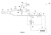
図8は、本システムの一実施形態による2つの光源を利用する問合わせ検出器システム160を表した概要図である。問合わせ検出器システム160は2種類の中心波長をもつ2つのLED162及び164を含む。光結合器166は、この2つのLEDからの2つの光信号168及び170を合成し、合成又は結合された光信号172を光ファイバ48を通してセンサ42に送っている。一実施形態ではそのLEDは1310nmと1550nmの中心波長を有する。別々の光源162、164を用いることによって、キャビティ深度に対する感度を最適化させるような波長を選択することが可能である。間隔を広く隔てた波長を用いることによって、計測の感度が増大する。システム160は、低コストかつ仕様保証で大量に製作できる遠距離通信対応のレーザー又はLED光源や入手が容易なインラインファイバ式WDM結合器などのより低コストの構成要素を利用している。システム160の利点の1つは、波長の分離幅が広く、これにより精細な線源波長の選択が柔軟にできることである。
FIG. 8 is a schematic diagram illustrating an
図9は、図8の2つの光信号168及び170の反射並びに2つの反射の比を、センサ42内のキャビティギャップに対して表したグラフ180である。水平軸181はマイクロメートルを単位としたキャビティギャップを表しており、また垂直軸182は任意単位の光強度を表している。曲線184は図8の光信号168の反射のプロットであり、また曲線185は図8の光信号170の反射のプロットである。曲線186は2つの反射信号184及び185の比のプロットである。図9から確認できるように、このプロットの動作スロープ領域188は図7の動作スロープ領域148と同様、すなわちより線形性がよくかつより幅広である。したがってこの実施形態ではさらに、キャビティ製造に関する許容差を緩和させることができる。別の実施形態では、同相モード光変動の影響を最小化するために、光源に対する閉ループ制御を使用することがある。
FIG. 9 is a
図10は、本発明の一実施形態による光源波長制御を利用する問合わせ検出器システム200を表した概要図である。一実施形態では、圧力変動だけを計測する(かつ、定常状態圧力を計測しない)場合、2つのフォトダイオード60、62により計測される定常状態光パワーを用いて光源44の波長を安定化させることがある。線源波長は典型的には、処理回路70からのフィードバック信号に基づいて線源電流及び/又は線源温度を調節することによって制御される。図8に示した実施形態では、2つのフォトダイオード60、62により計測されるパワーはそれぞれ、信号減結合器202及び204によってAC及びDC信号に減結合される。AC信号は、上述したように圧力変動の決定に使用される。DC信号は、光源44に対するフィードバック信号を作成するために処理回路70によって使用される。処理回路は、2つのフォトダイオード60、62により計測されるDCエネルギー比が一定に保たれるようにフィードバック信号を発生させている。DCエネルギー比を一定に保つことによって、フィルタの遮断波長及び光源中心波長のドリフトを完全に補償することができる。さらに本システム及び処理によれば、光源に対する単独の波長又は温度制御器が不要であり、これにより線源電子回路の複雑性が大幅に軽減される。上述した光源波長制御スキームはまた、2つの光源162及び164の波長又はパワーを制御するために図8の2光源構成でも利用できることに留意すべきである。
FIG. 10 is a schematic diagram illustrating an
図11は、本発明の一実施形態による別の光源波長制御システム210を表した概要図である。システム210は2つの光源を利用する図8のシステム160と同様である。しかしこの構成では、光結合器166の出力信号172を別の光結合器212によって2つの等しい信号216及び214に分割している。次いで信号216は、図8の構成の場合と同様に圧力計測のためにセンサ42に送られる。しかし信号214は、基準信号として処理回路218に送られ、2つの光源162及び164の光源波長及び/又は光源パワーの安定化のために使用される。これにより検知機能が安定化/制御機能から分離される。一実施形態では、2つの処理回路218及び70を1つの処理回路に合成させることがある。当業者であれば同様のスキームを図2、4及び6の単一光源構成の場合に用いることができることを理解されよう。しかしこれらの構成では、必ずしも光結合器166を必要としないことがある。光源の波長又はパワーを制御する同様の別のスキームも本問合わせシステムの趣旨域内にあることに留意すべきである。
FIG. 11 is a schematic diagram illustrating another light source
図12は、圧力センサに対する問合わせの工程を表した流れ図220である。工程222では圧力センサのファブリ・ペローキャビティギャップに単一又は複数の光信号が提供される。一実施形態ではその光信号は、LEDなどの光源によって提供され光ファイバを通してキャビティギャップに送られることがある。工程224では、キャビティギャップから反射された信号が光結合器によって受け取られる。圧力センサ内のキャビティギャップは石英サブストレート製のダイアフラムによって形成される。このダイアフラムは加えられた圧力に応答し、キャビティギャップ距離に変化を生じさせる。キャビティギャップからの反射信号は、キャビティギャップ距離の変化に従って変化する。工程226では、光結合器が反射信号を2つの部分(すなわち、第1の信号と第2の信号)に分割する。その信号は、工程228において任意選択でフィルタ処理されることがある。次いで、得られた信号を解析しファブリ・ペローキャビティ内の屈曲が、したがって圧力230が決定される。一実施形態では、2つの信号に関する光強度の比をとることによって圧力が決定される。別の実施形態では、2つの信号の強度の差し引きによって圧力が決定される。
FIG. 12 is a
本発明のある種の特徴についてのみ本明細書において図示し説明してきたが、当業者によって多くの修正や変更がなされるであろう。したがって、添付の特許請求の範囲が本発明の真の精神の範囲に属するこうした修正や変更のすべてを包含させるように意図したものであることを理解されたい。 Although only certain features of the invention have been illustrated and described herein, many modifications and changes will occur to those skilled in the art. Accordingly, it is to be understood that the appended claims are intended to cover all such modifications and changes as fall within the true spirit of the invention.
Claims (10)
光学式圧力センサ(42)から反射された信号(50)を受け取り、該反射信号を分割し、かつ該反射信号(50)の第1の部分(56)を第1の光検出器(60)に提供するための光結合器(54)と、
前記反射信号(50)の第2の部分(58)を受け取り、フィルタ処理済み信号(68)を第2の光検出器(62)に提供するためのフィルタ(64)と、
前記第1及び第2の光検出器出力信号の光強度同士の除算又は減算に基づいて圧力を取得するように構成された処理回路(70)と、
を備える光学式圧力センサ問合わせシステム(40)であって、
該処理回路(70)はさらに光信号の波長を制御するために光源に対してフィードバック信号を提供するように構成される、光学式圧力センサ問合わせシステム(40)。 A light source (44) for providing an optical signal (46) to the optical pressure sensor (42);
Receives the reflected signal (50) from the optical pressure sensor (42), splits the reflected signal, and converts the first portion (56) of the reflected signal (50) to the first photodetector (60). An optical coupler (54) for providing to
A filter (64) for receiving a second portion (58) of the reflected signal (50) and providing a filtered signal (68) to a second photodetector (62);
A processing circuit (70) configured to obtain a pressure based on a division or subtraction of light intensities of the first and second photodetector output signals;
An optical pressure sensor inquiry system (40) comprising:
The optical pressure sensor query system (40), wherein the processing circuit (70) is further configured to provide a feedback signal to the light source to control the wavelength of the optical signal.
光学式圧力センサ(42)から反射された信号(50)を受け取り、該反射信号を分割し、かつ該反射信号(50)の第1の部分(56)は高域通過フィルタ(102)にまた該反射信号(50)の第2の部分(58)は低域通過フィルタ(104)に提供するための光結合器(54)と、
前記高域通過フィルタ(102)から第1のフィルタ処理済み信号(56)を受け取るための第1の光検出器(60)と、
前記低域通過フィルタ(104)から第2のフィルタ処理済み信号(58)を受け取るための第2の光検出器(62)と、
前記第1及び第2の光検出器出力信号の光強度同士の関係に基づいて圧力を取得するように構成された処理回路(70)と、
を備える光学式圧力センサ問合わせシステム(100)。 A light source (44) for providing an optical signal (46) to the optical pressure sensor (42);
Receives the reflected signal (50) from the optical pressure sensor (42), splits the reflected signal, and the first portion (56) of the reflected signal (50) also passes to the high pass filter (102). An optical coupler (54) for providing a second portion (58) of the reflected signal (50) to a low pass filter (104);
A first photodetector (60) for receiving a first filtered signal (56) from the high pass filter (102);
A second photodetector (62) for receiving a second filtered signal (58) from the low pass filter (104);
A processing circuit (70) configured to obtain pressure based on a relationship between light intensities of the first and second photodetector output signals;
An optical pressure sensor inquiry system (100) comprising:
光学式圧力センサ(42)から反射された信号(50)を受け取り、該反射信号を分割してフィルタ処理し、かつ該反射信号の低域通過フィルタ処理済み信号(134)を第1の光検出器(62)に提供するための3ポートフィルタ(132)と、
前記3ポートフィルタ(132)から前記反射信号(50)の高域フィルタ処理済み信号(136)を受け取るための第2の光検出器(60)と、
前記第1及び第2の光検出器出力信号の光強度同士の関係に基づいて圧力を取得するように構成された処理(70)回路と、
を備える光学式圧力センサ問合わせシステム(130)。 A light source (44) for providing an optical signal (46) to the optical pressure sensor (42);
A reflected signal (50) is received from the optical pressure sensor (42), the reflected signal is split and filtered, and a low pass filtered signal (134) of the reflected signal is first detected. A three-port filter (132) for providing to the vessel (62);
A second photodetector (60) for receiving a high-pass filtered signal (136) of the reflected signal (50) from the three-port filter (132);
A processing (70) circuit configured to obtain pressure based on the relationship between the light intensities of the first and second photodetector output signals;
An optical pressure sensor inquiry system (130) comprising:
前記第1の光信号(168)及び第2の光信号(171)を受け取りかつ結合させた信号(172)を光学式圧力センサ(42)に提供するための第1の光結合器(166)と、
光学式圧力センサ(42)から反射された信号(50)を受け取り、該反射信号(50)を分割し、かつ該反射信号の第1の部分(56)は第1の光検出器(60)にまた該反射信号の第2の部分(58)は第2の光検出器(62)に提供するための第2の光結合器(54)と、
前記第1及び第2の光検出器出力信号の光強度同士の関係に基づいて圧力を取得するように構成された処理回路(70)と、
を備える光学式圧力センサ問合わせシステム(160)であって、
該処理回路(70)はさらに、第1及び第2の光信号の波長を制御するために第1及び第2の光源にフィードバック信号を提供するように構成される、光学式圧力センサ問合わせシステム(160)。 A first light source (162) and a second light source (164) for providing a first optical signal (168) and a second optical signal (170);
A first optical coupler (166) for providing an optical pressure sensor (42) with a signal (172) received and combined with the first optical signal (168) and the second optical signal (171). When,
Receives a reflected signal (50) from an optical pressure sensor (42), splits the reflected signal (50), and a first portion (56) of the reflected signal is a first photodetector (60). And a second optical coupler (54) for providing a second portion (58) of the reflected signal to a second photodetector (62);
A processing circuit (70) configured to obtain pressure based on a relationship between light intensities of the first and second photodetector output signals;
An optical pressure sensor inquiry system (160) comprising:
The processing circuit (70) is further configured to provide a feedback signal to the first and second light sources to control the wavelengths of the first and second optical signals. (160).
前記光学式圧力センサから反射された信号を第1の信号と第2の信号に分割する工程(226)と、
第1及び第2の光検出器出力信号の光強度同士の減算に基づいて圧力を取得するためにフィルタ処理した第1の信号と第2の信号とを解析する工程(230)と
を含む光学式圧力センサを問合わせる方法(220)。 Providing an optical signal to an optical pressure sensor (222);
Dividing the signal reflected from the optical pressure sensor into a first signal and a second signal (226);
An optical including a step (230) of analyzing the first signal and the second signal filtered to obtain pressure based on subtraction between the light intensities of the first and second photodetector output signals. To query the pressure sensor (220).
Applications Claiming Priority (1)
| Application Number | Priority Date | Filing Date | Title |
|---|---|---|---|
| US12/413,812 US8199334B2 (en) | 2009-03-30 | 2009-03-30 | Self-calibrated interrogation system for optical sensors |
Publications (2)
| Publication Number | Publication Date |
|---|---|
| JP2010237205A true JP2010237205A (en) | 2010-10-21 |
| JP2010237205A5 JP2010237205A5 (en) | 2012-08-30 |
Family
ID=42289623
Family Applications (1)
| Application Number | Title | Priority Date | Filing Date |
|---|---|---|---|
| JP2010071272A Pending JP2010237205A (en) | 2009-03-30 | 2010-03-26 | Self-calibrated interrogation system for photo-sensor |
Country Status (4)
| Country | Link |
|---|---|
| US (1) | US8199334B2 (en) |
| EP (1) | EP2237008A3 (en) |
| JP (1) | JP2010237205A (en) |
| CA (1) | CA2697814C (en) |
Cited By (1)
| Publication number | Priority date | Publication date | Assignee | Title |
|---|---|---|---|---|
| JP2014041054A (en) * | 2012-08-22 | 2014-03-06 | Japan Atomic Energy Agency | Moisture sensor |
Families Citing this family (8)
| Publication number | Priority date | Publication date | Assignee | Title |
|---|---|---|---|---|
| US9932852B2 (en) * | 2011-08-08 | 2018-04-03 | General Electric Company | Sensor assembly for rotating devices and methods for fabricating |
| GB2511803B (en) * | 2013-03-14 | 2015-07-29 | Kidde Tech Inc | Pneumatic sensing apparatus |
| CA2909947C (en) * | 2013-04-25 | 2020-06-30 | Sentek Instrument LLC | Sapphire sensor for measuring pressure and temperature |
| US20150100253A1 (en) * | 2013-10-09 | 2015-04-09 | Parker-Hannifin Corporation | Aircraft fluid gauging techniques using pressure measurements and optical sensors |
| ES2670015T3 (en) * | 2015-05-12 | 2018-05-29 | Braun Gmbh | Personal hygiene device with treatment force measurement unit |
| US9945740B2 (en) * | 2015-05-14 | 2018-04-17 | Kulite Semiconductor Products, Inc. | Two wavelength optical interferometric pressure switch and pressure transducers |
| CN105136379A (en) * | 2015-07-17 | 2015-12-09 | 中国电子科技集团公司第四十九研究所 | Dynamic pressure sensor chip |
| CN113916438B (en) * | 2021-12-08 | 2022-02-25 | 广东海洋大学 | Fabry-Perot interference optical fiber pressure sensor for eliminating temperature interference and manufacturing method thereof |
Citations (6)
| Publication number | Priority date | Publication date | Assignee | Title |
|---|---|---|---|---|
| JPS62217132A (en) * | 1985-12-30 | 1987-09-24 | テクノロジ− ダイナミツクス インコ−ポレ−テツド | Optical type pressure detection system |
| JPH08304541A (en) * | 1995-05-15 | 1996-11-22 | Mitsubishi Electric Corp | Laser radar equipment |
| JP2001053681A (en) * | 1999-08-04 | 2001-02-23 | Nortel Networks Ltd | Two-stage module type broadband optical amplifier |
| JP2003503727A (en) * | 1999-07-06 | 2003-01-28 | サンバ センサーズ アーベー | Methods and devices for fiber optic measurement systems |
| US6792023B1 (en) * | 1998-06-04 | 2004-09-14 | Lambda Physik Ag | Method and apparatus for reduction of spectral fluctuations |
| US7016047B2 (en) * | 2002-09-26 | 2006-03-21 | Prime Photonics, Inc. | Active Q-point stabilization for linear interferometric sensors |
Family Cites Families (16)
| Publication number | Priority date | Publication date | Assignee | Title |
|---|---|---|---|---|
| US4703175A (en) * | 1985-08-19 | 1987-10-27 | Tacan Corporation | Fiber-optic sensor with two different wavelengths of light traveling together through the sensor head |
| US4712004A (en) * | 1986-08-20 | 1987-12-08 | Simmonds Precision Products, Inc. | Method and apparatus for compensating fiber optic lead and connector losses in a fiber optic sensor by using a broadband optical source and multiple wave retardation |
| US5606170A (en) * | 1995-02-03 | 1997-02-25 | Research International, Inc. | Multifunctional sensor system |
| US5742200A (en) * | 1996-05-14 | 1998-04-21 | Alliedsignal Inc. | Environmentally rugged optical sensor with improved noise cancellation |
| US5929990A (en) * | 1997-03-19 | 1999-07-27 | Litton Systems, Inc. | Fabry-perot pressure sensing system with ratioed quadrature pulse detection |
| AU2001234961A1 (en) * | 2000-02-11 | 2001-08-20 | Rosemount, Inc. | Optical pressure sensor |
| CA2497842C (en) * | 2002-09-06 | 2012-07-10 | Anbo Wang | Intrinsic fabry-perot optical fiber sensors and their multiplexing |
| US7054011B2 (en) * | 2003-09-04 | 2006-05-30 | Virginia Tech Intellectual Properties, Inc. | Optical fiber pressure and acceleration sensor fabricated on a fiber endface |
| US7173713B2 (en) * | 2004-03-04 | 2007-02-06 | Virginia Tech Intellectual Properties, Inc. | Optical fiber sensors for harsh environments |
| US20050195402A1 (en) * | 2004-03-04 | 2005-09-08 | Russell May | Crystalline optical fiber sensors for harsh environments |
| EP1586854A3 (en) * | 2004-04-15 | 2006-02-08 | Davidson Instruments | Interferometric signal conditioner for measurement of the absolute length of gaps in a fiber optic Fabry-Pérot interferometer |
| US7313965B2 (en) * | 2004-12-27 | 2008-01-01 | General Electric Company | High-temperature pressure sensor |
| JP4817786B2 (en) * | 2005-10-03 | 2011-11-16 | 株式会社山武 | Differential pressure measurement system and differential pressure measurement method |
| AU2005225034B2 (en) * | 2005-10-18 | 2011-08-11 | The Australian National University | Interferometric sensor |
| US7551295B2 (en) * | 2006-06-01 | 2009-06-23 | Symphony Acoustics, Inc. | Displacement sensor |
| US20080106745A1 (en) * | 2006-08-31 | 2008-05-08 | Haber Todd C | Method and apparatus for high frequency optical sensor interrogation |
-
2009
- 2009-03-30 US US12/413,812 patent/US8199334B2/en active Active
-
2010
- 2010-03-18 EP EP10156975.4A patent/EP2237008A3/en not_active Withdrawn
- 2010-03-25 CA CA2697814A patent/CA2697814C/en not_active Expired - Fee Related
- 2010-03-26 JP JP2010071272A patent/JP2010237205A/en active Pending
Patent Citations (6)
| Publication number | Priority date | Publication date | Assignee | Title |
|---|---|---|---|---|
| JPS62217132A (en) * | 1985-12-30 | 1987-09-24 | テクノロジ− ダイナミツクス インコ−ポレ−テツド | Optical type pressure detection system |
| JPH08304541A (en) * | 1995-05-15 | 1996-11-22 | Mitsubishi Electric Corp | Laser radar equipment |
| US6792023B1 (en) * | 1998-06-04 | 2004-09-14 | Lambda Physik Ag | Method and apparatus for reduction of spectral fluctuations |
| JP2003503727A (en) * | 1999-07-06 | 2003-01-28 | サンバ センサーズ アーベー | Methods and devices for fiber optic measurement systems |
| JP2001053681A (en) * | 1999-08-04 | 2001-02-23 | Nortel Networks Ltd | Two-stage module type broadband optical amplifier |
| US7016047B2 (en) * | 2002-09-26 | 2006-03-21 | Prime Photonics, Inc. | Active Q-point stabilization for linear interferometric sensors |
Cited By (1)
| Publication number | Priority date | Publication date | Assignee | Title |
|---|---|---|---|---|
| JP2014041054A (en) * | 2012-08-22 | 2014-03-06 | Japan Atomic Energy Agency | Moisture sensor |
Also Published As
| Publication number | Publication date |
|---|---|
| CA2697814C (en) | 2017-07-04 |
| US8199334B2 (en) | 2012-06-12 |
| EP2237008A3 (en) | 2016-07-27 |
| CA2697814A1 (en) | 2010-09-30 |
| US20100245840A1 (en) | 2010-09-30 |
| EP2237008A2 (en) | 2010-10-06 |
Similar Documents
| Publication | Publication Date | Title |
|---|---|---|
| JP2010237205A (en) | Self-calibrated interrogation system for photo-sensor | |
| US11150144B2 (en) | Sapphire sensor for measuring pressure and temperature with improved stress and temperature variation compensation | |
| US5963321A (en) | Self-calibrating optical fiber pressure, strain and temperature sensors | |
| JP6167117B2 (en) | Optical sensor | |
| US7966887B2 (en) | High temperature optical pressure sensor and method of fabrication of the same | |
| JP6170514B2 (en) | Optical pressure sensor | |
| US10184852B2 (en) | Sensor system comprising multiplexed fiber-coupled fabry-perot sensors | |
| US7626707B2 (en) | Dual cavity displacement sensor | |
| US5258614A (en) | Optical fiber loop temperature sensor | |
| US5196694A (en) | Temperature compensated self-referenced fiber optic microbend pressure transducer | |
| EP2839554A1 (en) | Frequency tunable laser system | |
| US11293799B2 (en) | Chromatic confocal sensor | |
| US20050259270A1 (en) | Fiberoptic fabry-perot optical processor | |
| Xiao-qi et al. | An optical fibre MEMS pressure sensor using dual-wavelength interrogation | |
| US20080055604A1 (en) | Apparatus, method and computer program product for interrogating an optical sensing element | |
| JP2014062895A (en) | Optical fiber sensor by mems diaphragm etalon and measuring system thereby | |
| Xiao | Self-calibrated interferometric/intensity based fiber optic pressure sensors | |
| HAYBER et al. | Selection of Fiber Optic Fabry-Perot Interferometer Parameter for Acoustic Sensing Applications | |
| CN114034300A (en) | Optical accelerometer and inertial navigation system | |
| JP2014130071A (en) | Optical sensing system, optical sensing method, and interrogator based on light zero method | |
| Saaski et al. | Multimode fiber optic pressure sensor with extended range | |
| Kiesel et al. | Compact and fast interrogation unit for fiber Bragg grating sensors | |
| Njegovec et al. | Optical signal processing device for optical sensors interrogation | |
| JPS62161003A (en) | Optical sensor | |
| Wang et al. | The signal interrogation technology of MEMS optical fiber pressure sensor |
Legal Events
| Date | Code | Title | Description |
|---|---|---|---|
| A521 | Written amendment |
Free format text: JAPANESE INTERMEDIATE CODE: A523 Effective date: 20120718 |
|
| A621 | Written request for application examination |
Free format text: JAPANESE INTERMEDIATE CODE: A621 Effective date: 20120718 |
|
| A871 | Explanation of circumstances concerning accelerated examination |
Free format text: JAPANESE INTERMEDIATE CODE: A871 Effective date: 20120718 |
|
| A975 | Report on accelerated examination |
Free format text: JAPANESE INTERMEDIATE CODE: A971005 Effective date: 20120731 |
|
| A131 | Notification of reasons for refusal |
Free format text: JAPANESE INTERMEDIATE CODE: A131 Effective date: 20120925 |
|
| A521 | Written amendment |
Free format text: JAPANESE INTERMEDIATE CODE: A523 Effective date: 20121217 |
|
| A02 | Decision of refusal |
Free format text: JAPANESE INTERMEDIATE CODE: A02 Effective date: 20130115 |