JP2010216217A - Handrail for sliding door - Google Patents
Handrail for sliding door Download PDFInfo
- Publication number
- JP2010216217A JP2010216217A JP2009096470A JP2009096470A JP2010216217A JP 2010216217 A JP2010216217 A JP 2010216217A JP 2009096470 A JP2009096470 A JP 2009096470A JP 2009096470 A JP2009096470 A JP 2009096470A JP 2010216217 A JP2010216217 A JP 2010216217A
- Authority
- JP
- Japan
- Prior art keywords
- handrail
- sliding door
- door
- bracket
- bar
- Prior art date
- Legal status (The legal status is an assumption and is not a legal conclusion. Google has not performed a legal analysis and makes no representation as to the accuracy of the status listed.)
- Pending
Links
Images


Abstract
Description
この発明は、高齢者や傷病者等の歩行を助けるための手摺りであって、引き戸の表面に取りつけても戸の開閉が出来る手摺りに関する。 The present invention relates to a handrail for assisting walking of an elderly person, a sick person, and the like and capable of opening and closing the door even when attached to the surface of a sliding door.
従来、住宅・病院・養護施設等建物の廊下の壁には、歩行の安全を確保するために手摺りが付けられているが、各部屋への出入口の部分は手摺りが途切れていて頼れるものがない。扉がドアーのように蝶番によって開閉する場合は、扉に手摺りが付けられていても扉の開閉に何ら支障はないので、稀に手摺りが付けられている事もある。またドアーの取っ手の形を変えて手摺りと兼用できるものまである。しかし、開閉の為の構造がレールと戸車による引き戸の場合には、手摺りが戸の表面から少しでも出っ張っていると、手摺りが戸枠にぶつかるので戸を開けることができない。この状況を考慮して考え出された発明は幾つも見受けられるが、どの技術も利用されるには至っていない。 Conventionally, handrails have been attached to the walls of corridors in buildings such as houses, hospitals, nursing homes, etc., to ensure the safety of walking. There is no. When the door is opened and closed by a hinge like a door, even if a handrail is attached to the door, there is no hindrance to opening and closing the door, so a handrail may be attached rarely. There are even things that can be used as a handrail by changing the shape of the handle of the door. However, in the case where the structure for opening and closing is a sliding door using rails and a door pulley, if the handrail protrudes even slightly from the surface of the door, the handrail hits the door frame, so the door cannot be opened. Many inventions have been devised in view of this situation, but no technology has been used.
この発明は、高齢者や傷病者等の歩行の安全をを補助するための手摺りであって、引き戸の表面に取りつけても戸の開閉が出来るようにするために、引き戸の開き側の表面に固定板と回動自在の支持体と係止具を備えたブラケットを取り付け、手摺り棒の基端部は係止具を介してブラケットに固定し、且手摺り棒の他端部は壁又は竪枠等に設けた受け具によって水平に保持される。そしてこの他端部は引き戸の開閉動作に連動して壁又は竪枠等に沿って上下摺動するようにしている。 The present invention is a handrail for assisting the safety of walking of elderly people and victims, etc., and in order to be able to open and close the door even if attached to the surface of the sliding door, the surface on the opening side of the sliding door Attach a bracket with a fixed plate, a rotatable support, and a locking tool, and fix the base end of the handrail bar to the bracket via the locking tool, and the other end of the handrail bar to the wall Or it hold | maintains horizontally with the receiving tool provided in the eaves frame etc. And this other end part is made to slide up and down along a wall or a fence frame etc. in response to opening and closing operation of a sliding door.
特許文献1によると、二枚の引き戸にそれぞれ太さが異なる中空の手摺り棒が付けられていて、引き戸を開ける時、太い方の手摺りの中に細い手摺りが入り込むようにしてあり、そして二枚の引き戸と手摺りに係わるようにラッチが付けられている。
課題としては先ず、手摺りを取り付けるためのブラケットの引き戸の表面からの摺りの持ち出し幅であるが、戸の厚さは通常引き戸の種類によって異なることを考えると、その条件には対応できていない。ラッチについては、バネを必要とするなど構造があまりに複雑なために制作費が嵩むばかりか、此れを取り付けるために戸を切り抜く等の加工を施す必要があり、手間と加工技術が求められる。特に金属製の引き戸においては加工が極めて困難である。また、ラッチは人が手摺りに頼ったとき、引き戸を開ける動作より先に手摺りを下降させて引き戸が動かないよいにする為のもので二段動作であり、手摺りを降下させる前に引き戸が少しでも動いてしまうとラッチが掛からなくなって極めて危険である。また引き戸を外すときは、戸を持つために両方の戸を少し開けなければならないが、それによって手摺りがより深く繋がってしまい、二枚の引き戸を一緒に持つことになるので非常に困難である。
特許文献2は、人が引き戸の手前側から向こう側に移動する場合、引き戸を開ける以前に手摺りを踏み切りの遮断機のように90度動かさなければならないので二度手間である上に、向こう側に移動した後、引き戸を閉める前にわざわざ手摺りを元の位置に戻さなければならない。また、向こう側から引き戸を開けたときには手摺りを動かしにくいものと考えられる。
その他この種類の出願は数多く成されているが、いずれの文献も構造は異なるものの特許文献1及び特許文献2と同様の欠点がある。According to
The first issue is the width of the sliding door from the surface of the sliding door of the bracket for attaching the handrail. However, considering that the thickness of the door usually varies depending on the type of the sliding door, the condition cannot be met. . For the latch, the structure is so complicated as to require a spring, so that the production cost is high, and it is necessary to perform processing such as cutting out a door to attach this, and labor and processing technology are required. In particular, it is extremely difficult to process a metal sliding door. In addition, the latch is a two-stage operation that lowers the handrail so that the sliding door does not move before opening the sliding door when a person relies on the handrail. If the sliding door moves even a little, it will not be latched and it is extremely dangerous. Also, when removing the sliding doors, you have to open both doors a little to hold the doors, but this is very difficult because the handrails are connected deeper and you have two sliding doors together. is there.
In
Many other applications of this type have been made, but each document has the same drawbacks as
この発明は上記の課題を解消するために次のような構成としている。即ち、図1及び図4に示すように、固定板22と回動支持体24と係止具26を備えたブラケット21は固定板22によって引き戸1の適宜な高さにビス固定していて、手摺り棒11は基端12の部分で前記係止具26によってブラケット21に固定され、且つ他端部13は竪枠B6に設けた受け具31の凹部32(図5)に嵌まることによって水平に保持されてる。 The present invention has the following configuration in order to solve the above problems. That is, as shown in FIGS. 1 and 4, the
この発明の作用を図1・図2・図3・図4・図5に基づいて詳細に説明する。
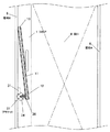
図1に示すように、引き戸1に適宜な高さを以て水平に位置させた手摺り棒11は、基端部12を引き戸1の開く側にブラケット21を介して取り付け、長さは他端部13が竪枠B6に接する迄として、その手摺り棒11の他端部13が、竪枠B6に接する位置に受け具31を取りつけている。また手摺り棒11の水平芯は回動芯25より上に位置していことによって、 引き戸1を開ける時には以下に述べる作用を示す。
詰まり、引き戸1を開き方向(矢印A)に移動するとき、図2に示すように、手摺り棒11はその他端部13が竪枠B6につかえて移動できないので、手摺り棒11は回動支持体24と共に回動芯25を軸にして戸と逆の方向(矢印B)に回る、更に引き戸1の移動を続けると、他端部13が竪枠B6の表面を上方向に摺動するのと共に回動支持体24も回り続け、更に図3に示すように引き戸1を開けきったときには手摺り棒11はほぼ垂直の状態になる。そして、引き戸1を閉めるときには、開けるときとは全く逆の動き方をして、引き戸1が完全に閉まるのと同時に他端部13は受け具31に納まって、再び手摺りとして使用できるようになる。
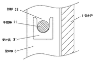
図4は前記ブラケット21の断面図であって、引き戸1の表面にビス固定した固定板22はその表面に回動自在の回動支持体24を備え、その上部には係止具26を介して手摺り棒11をビス固定している。
図5は前記受け具31に形成した凹部32に手摺り棒が納まった状態を示している。The operation of the present invention will be described in detail with reference to FIG. 1, FIG. 2, FIG. 3, FIG.
As shown in FIG. 1, a
When the sliding
FIG. 4 is a cross-sectional view of the
FIG. 5 shows a state in which the handrail bar is housed in the recess 32 formed in the
この発明は上記の構成によって次に述べる効果が得られる。
1.引き戸が閉まっているときは手摺り棒は手摺りとしての機能を発揮し、その状態のまま引き戸を開けることができ、閉めるときもそのまま普通に閉めるだけでよい。従って手摺り付きの引き戸でありながら、従来の引き戸と全く同じ動作で使用できるものである。
2.手摺り棒の取りつけ方がブラケットと受け具を引き戸と竪枠等にそれぞれビス固定するだけで良く、引き戸や建物への加工がないので、取り付け費用が安価な上に、素人でも簡単に取り付けることができる。
3.取り付け方法がビスのみによるので、建物の新築・既存を問うことなく殆どの引き戸に取り付けることができる。
4.左右に開く二枚引き戸の場合でも、ブラケットの係止具に手摺り棒を逆向きに付けることで左右兼用にできるので安価にて製造できる。
5,引き戸を外す場合は、戸を持つために少し開けると、それと同時に手摺り棒の他端部が受け具から離れるので一人でも容易に外すことができる。In the present invention, the following effects can be obtained by the above configuration.
1. When the sliding door is closed, the handrail bar functions as a handrail, and the sliding door can be opened in that state, and when closing, it can be closed normally. Therefore, although it is a sliding door with a handrail, it can be used in exactly the same operation as a conventional sliding door.
2. The handrail stick can be attached simply by screwing the bracket and bracket to the sliding door and frame, etc., and there is no processing to the sliding door or building. Can do.
3. Since the installation method is only screws, it can be installed on most sliding doors without questioning whether the building is new or existing.
4). Even in the case of a double sliding door that opens to the left and right, it can be manufactured at low cost because it can be used for both the left and right sides by attaching a handrail bar to the bracket locking tool in the opposite direction.
5. When removing the sliding door, it can be easily removed by one person because the other end of the handrail bar is separated from the receiving device at the same time if it is opened a little to hold the door.
1:引き戸 2:引き戸A 3:取っ手 4:敷居
5:竪枠A 6;竪枠B 7:鴨居 8:開口部
11:手摺り棒 12:基端部 13:他端部
14:ガイドローラー 15:軸凸部 16:ローラー支持体
21:ブラケット 22:固定板 23:ビス孔 24:回動支持体
25:回動芯 26:係止具 27:ビス孔
31:受け具 32:凹部 33:ガイドレール
34:ガイド溝 35:曲り部 36:切り欠き部 37:鍔部1: sliding door 2: sliding door A 3: handle 4: sill 5:
図6・図7・図8・図9に基づいて実施例1を詳細に説明する。
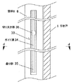
図6は縦枠A5・竪枠B6・及び図示はしていないが敷居4・鴨居7から成る引き戸用の枠に一枚の引き戸1を嵌めた正面図であって、固定板22と回動支持体24と係止具26を備えたブラケット21は、固定板22によって引き戸1の開き側の適宜な高さにビス固定していて、手摺り棒11は基端部12の部分で係止部26を介してブラケット21に固定され、他端部13にはローラー支持体16を介してガイドローラー14を備えている。このガイドローラー14にはローラーの軸を延長する形に軸凸部15をローラー支持体16の両側に形成している。
竪枠B6には図1に示す受け具31に変えて、直線状のガイド溝34と曲り部35からなるガイドレール33を設けている。
此のガイドレール33は、図9の断面図に示すように内部にガイド溝34を構成し、下端部には図6に示すように曲り部35を形成すると共に、上方に延びる直線状のガイドレ−ルは、引き戸1を全開にした時、詰まりガイドローラー14が最上部に達した時の高さを補う長さとしている。更にガイドレール33の中央付近には引き戸1を外すときにガイドローラー14を引き出す為の切り欠き部36を設けている。そしてガイド溝34の幅は、曲り部35の部分で下に向うに従って微妙に狭くしてあり、その幅は前記ガイドローラー14の先端と軸凸部15距離に合わせて、ガイドローラーと軸凸部が丁度嵌まるものとしている。
このガイドローラー14と軸凸部15を同一部材で兼用しても良く、更にガイドローラーと軸凸部とローラー支持体16を一体に構成して一つのユニットとし、このユニッを手摺り棒の他端部に装着固定ができるようにすると、手摺り棒の長さを切り詰める等の調整も可能になる。
上記の構成による実施例1には次に述べる効果がある。
1.手摺り棒の他端部に設けたガイドローラーの働きによって、引き戸の開閉に伴う上下の動きが極めて滑らかにすることができる。更に、手摺りの水平方向の移動に対してガイドローラーは上下方向の動きであるから、ローラーと言えども引き戸の初動時には多少の抵抗が生じるが、ガイド溝の下端部に形成した曲り部によって引き戸の初動時の抵抗を殆ど無くすことができる。
2.引き戸を閉め切った状態のとき、手摺棒の他端部の可動方向は曲り部の角度、詰まり斜め上の方向のみであって、この方向以外に手摺り棒が動くことはない。普通人が手摺りに頼ったとき、手摺りに掛かる力は主に下方向であって、力が斜め上の方向に働くとは考えにくい。従って意図的に斜め上の方向に動かそうとしないかぎり、手摺り棒が動くことはないので、通常手摺りを使用する時は極めて安全である上に、そのままの姿勢で取っ手を引けば引き戸を開けることができる。The first embodiment will be described in detail with reference to FIGS. 6, 7, 8, and 9.
FIG. 6 is a front view in which a single sliding
A
The
The
The first embodiment having the above configuration has the following effects.
1. By the action of the guide roller provided at the other end of the handrail bar, the vertical movement accompanying the opening and closing of the sliding door can be made extremely smooth. Furthermore, since the guide roller moves in the vertical direction with respect to the horizontal movement of the handrail, even if it is a roller, some resistance is generated at the initial movement of the sliding door, but the sliding door is formed by the curved portion formed at the lower end of the guide groove. Most of the initial resistance can be eliminated.
2. When the sliding door is in a closed state, the movable direction of the other end of the handrail bar is only the angle of the bent part and the direction obliquely above the clogging, and the handrail bar does not move in any direction other than this direction. When an ordinary person relies on a handrail, the force applied to the handrail is mainly in the downward direction, and it is unlikely that the force works in an obliquely upward direction. Therefore, the handrail bar will not move unless it is intentionally moved in an obliquely upward direction, so it is extremely safe when using a handrail. In addition, if you pull the handle as it is, the sliding door can be moved. Can be opened.
図10に基づいて実施例2を詳細に説明する。
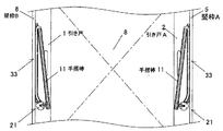
この実施例は、二枚の引き戸を中央から両側に向けて引き分けていて、病院や養護施設等に多く用いられているが、この方法によると、廊下の壁に付けられた手摺りが部屋への出入口の部分だけ付いていない。そして手摺りが無い部分の長さは最短でも2メートルに及ぶ。そこでこの実施例は、実施例1の構成のまま左右対象に使い分けたものでブラケット・手摺り棒・ガイドレールの各部材は左右の勝手が決められていないので、ガイドレールはそのまま逆に使用すれば良く、手摺り棒はその基端部を逆向きにして係止具の上に固定すると左右対称になり、2メートルに及ぶ引き戸の部分にも手摺りを付けることができる。
また、この構成によると左右対称の場合でも、同一の部品をそのまま使用できるので、製造単価が上がることはない。Example 2 will be described in detail with reference to FIG.
In this embodiment, two sliding doors are drawn from the center toward both sides and are often used in hospitals and nursing homes. However, according to this method, handrails attached to the walls of the corridor are moved to the room. Only the doorway part is not attached. And the length of the part without a handrail reaches at least 2 meters. Therefore, in this embodiment, the left and right sides of the bracket, handrail bar, and guide rail are not determined in the same manner as in the first embodiment, and the guide rail is used as it is. The handrail bar may be symmetrical when the base end of the handrail bar is reversed and fixed on the locking tool, and a handrail can be attached to the sliding door portion extending over 2 meters.
Further, according to this configuration, even in the case of left-right symmetry, the same parts can be used as they are, so that the manufacturing unit price does not increase.
図11・図12に基づいて実施例3を詳細に説明する。
この実施例は、図11に示すようにガイドレール33の周部に鍔部37を直線的に形成したもので、図12に示すように、ガイドレール33そのものを鍔部37と曲がり部35を残して竪枠Bの中に埋め込むと、出っ張りが少なくなる分引き戸を開けたときの開口が、広くなる上に、拭き掃除もし易く、デザイン的にも優れたものになる。
また、デザインの面から考えて、ブラケットの係止具を無くし、手摺り棒と回動支持体を一体に形成することも可能である。The third embodiment will be described in detail with reference to FIGS.
In this embodiment, as shown in FIG. 11, a
From the viewpoint of design, it is also possible to eliminate the bracket locking tool and integrally form the handrail bar and the rotation support.
Claims (6)
Priority Applications (1)
| Application Number | Priority Date | Filing Date | Title |
|---|---|---|---|
| JP2009096470A JP2010216217A (en) | 2009-03-18 | 2009-03-18 | Handrail for sliding door |
Applications Claiming Priority (1)
| Application Number | Priority Date | Filing Date | Title |
|---|---|---|---|
| JP2009096470A JP2010216217A (en) | 2009-03-18 | 2009-03-18 | Handrail for sliding door |
Publications (1)
| Publication Number | Publication Date |
|---|---|
| JP2010216217A true JP2010216217A (en) | 2010-09-30 |
Family
ID=42975325
Family Applications (1)
| Application Number | Title | Priority Date | Filing Date |
|---|---|---|---|
| JP2009096470A Pending JP2010216217A (en) | 2009-03-18 | 2009-03-18 | Handrail for sliding door |
Country Status (1)
| Country | Link |
|---|---|
| JP (1) | JP2010216217A (en) |
Cited By (3)
| Publication number | Priority date | Publication date | Assignee | Title |
|---|---|---|---|---|
| WO2011136164A1 (en) * | 2010-04-27 | 2011-11-03 | ケイ・プロダクツ株式会社 | Handrail for sliding door, sliding door apparatus |
| JP2013256808A (en) * | 2012-06-13 | 2013-12-26 | Kei Products Co Ltd | Handrail for sliding door and sliding door device |
| CN107893619A (en) * | 2017-12-16 | 2018-04-10 | 上海市房地产科学研究院(上海市住宅修缮工程质量检测中心) | A kind of the elderly's dedicated bathroom door and its application method |
-
2009
- 2009-03-18 JP JP2009096470A patent/JP2010216217A/en active Pending
Cited By (4)
| Publication number | Priority date | Publication date | Assignee | Title |
|---|---|---|---|---|
| WO2011136164A1 (en) * | 2010-04-27 | 2011-11-03 | ケイ・プロダクツ株式会社 | Handrail for sliding door, sliding door apparatus |
| JP2013256808A (en) * | 2012-06-13 | 2013-12-26 | Kei Products Co Ltd | Handrail for sliding door and sliding door device |
| CN107893619A (en) * | 2017-12-16 | 2018-04-10 | 上海市房地产科学研究院(上海市住宅修缮工程质量检测中心) | A kind of the elderly's dedicated bathroom door and its application method |
| CN107893619B (en) * | 2017-12-16 | 2023-12-26 | 上海市房地产科学研究院(上海市住宅修缮工程质量检测中心) | Bathroom door special for old people and application method thereof |
Similar Documents
| Publication | Publication Date | Title |
|---|---|---|
| US8950119B2 (en) | Window opening limit devices and method of use | |
| US11220845B2 (en) | Powered sash lock and control systems therefor | |
| JP2010216217A (en) | Handrail for sliding door | |
| KR101468950B1 (en) | Semi-auto sliding door lever lock device | |
| JP2008215052A (en) | Start assisting device of sliding door | |
| JP6480232B2 (en) | Sash with screen door | |
| JPH09273361A (en) | Hinged door for entrance/exit | |
| JP5827080B2 (en) | Self-closing sliding door | |
| KR200394870Y1 (en) | A opening and shutting equipment for a sliding window | |
| JP4601588B2 (en) | Sash with sub-block | |
| JP6423299B2 (en) | Sash with screen door | |
| JP2010043407A (en) | Rainwater infiltration prevention device of sliding door | |
| CN203822119U (en) | Burglarproof escape window | |
| JP4375936B2 (en) | Locking device for emergency entrance door of high-rise building | |
| JP5391108B2 (en) | Joinery | |
| JP4433414B2 (en) | Single window | |
| JP2007254963A (en) | Fittings | |
| JP3537430B1 (en) | High-watertight barrier-free sash opening restriction device | |
| KR200395663Y1 (en) | Swing door lock that works up, down, left and right | |
| JP2019035308A (en) | Sash opening assist device, and, fixture and architectural structure where sash opening assist device is attached | |
| JP2000240345A (en) | Fitting | |
| JP5894456B2 (en) | Opening-reducing tablet | |
| JP2011080200A (en) | Crescent lock | |
| JP2023055390A (en) | Locking device for emergency opening | |
| JP2010053604A (en) | Sliding door for building |