JP2010210285A - Method and device for detecting concentration of mixed fluid - Google Patents
Method and device for detecting concentration of mixed fluid Download PDFInfo
- Publication number
- JP2010210285A JP2010210285A JP2009054056A JP2009054056A JP2010210285A JP 2010210285 A JP2010210285 A JP 2010210285A JP 2009054056 A JP2009054056 A JP 2009054056A JP 2009054056 A JP2009054056 A JP 2009054056A JP 2010210285 A JP2010210285 A JP 2010210285A
- Authority
- JP
- Japan
- Prior art keywords
- mixed fluid
- temperature
- concentration
- component
- dielectric constant
- Prior art date
- Legal status (The legal status is an assumption and is not a legal conclusion. Google has not performed a legal analysis and makes no representation as to the accuracy of the status listed.)
- Granted
Links
Images


Abstract
Description
本発明は、3種以上の成分で構成される混合流体の濃度を検出する、混合流体の濃度検出方法および検出装置に関する。 The present invention relates to a mixed fluid concentration detection method and detection apparatus for detecting the concentration of a mixed fluid composed of three or more components.
近年、ガソリンの代替燃料としてアルコール類が注目され、例えばガソリンとエタノールを主成分とするバイオ混合ガソリンや、軽油と脂肪酸メチルエステルを主成分とするバイオ混合軽油のような混合燃料が普及し始めてきている。この種の混合燃料を用いて内燃機関の作動状態に適合した燃料量を燃焼室へ噴射できるようにするためには、ガソリンとアルコールの濃度を適宜検出して、アルコール含有量を絶えず把握する必要がある。このためのガソリンとアルコールの濃度検出装置が、例えば、特開平5−87764号公報(特許文献1)と特開2008−268169号公報(特許文献2)に開示されている。 In recent years, alcohol has attracted attention as an alternative fuel to gasoline, and mixed fuels such as bio-mixed gasoline mainly composed of gasoline and ethanol and bio-mixed light oil mainly composed of light oil and fatty acid methyl ester have started to spread. ing. In order to be able to inject into the combustion chamber a fuel amount suitable for the operating state of the internal combustion engine using this kind of mixed fuel, it is necessary to detect the concentration of gasoline and alcohol as needed and constantly grasp the alcohol content. There is. Gasoline and alcohol concentration detection devices for this purpose are disclosed in, for example, Japanese Patent Application Laid-Open No. 5-87764 (Patent Document 1) and Japanese Patent Application Laid-Open No. 2008-268169 (Patent Document 2).
例えば、特許文献1に開示されたアルコール含有量の検出装置は、ケーシング内に配置された一対の電極間に測定対象のガソリンとアルコールからなる混合燃料(混合流体)を導入し、混合燃料の静電容量(誘電率)を測定して、アルコールの濃度を測定する装置である。また、特許文献2に開示された液体性状センサは、半導体基板に設けられた櫛歯状電極をガソリン等の液体燃料の中に浸漬させて静電容量(誘電率)を測定し、ガソリンに含まれるアルコールの混合比率を検出するセンサである。
For example, the alcohol content detection device disclosed in
ところで、上記混合燃料にあっては、主成分であるガソリンとエタノール以外に、例えば水が混入することが知られている。詳しくは、精製段階においてエタノールに水が混入したり、混合燃料が大気に触れることで大気に含まれる水が混合燃料に溶け込んだり、混合燃料を運搬する際に人為的に水が混入したりすることが知られている。このように混合燃料に水が混入すると、混合燃料の静電容量(誘電率)は、ガソリン、エタノールおよび水の3成分の濃度(存在割合)に依存して変化することになる。しかしながら、上記従来技術においては、混合燃料がガソリンとアルコールで構成されているとみなされており、2成分の濃度しか測定できないため、水の混入により測定誤差が生じてしまう。 Incidentally, in the above mixed fuel, it is known that, for example, water is mixed in addition to gasoline and ethanol which are the main components. Specifically, water is mixed into ethanol during the refining stage, water contained in the atmosphere dissolves into the mixed fuel when it comes into contact with the atmosphere, or water is artificially mixed when transporting the mixed fuel. It is known. When water is mixed in the mixed fuel in this way, the electrostatic capacity (dielectric constant) of the mixed fuel changes depending on the concentrations (existence ratios) of the three components of gasoline, ethanol and water. However, in the above-described prior art, the mixed fuel is considered to be composed of gasoline and alcohol, and only the concentration of two components can be measured.
そこで本発明は、3種以上の成分で構成される混合流体の濃度を正確に検出することのできる、混合流体の濃度検出方法および検出装置を提供することを目的としている。 Therefore, an object of the present invention is to provide a mixed fluid concentration detection method and a detection device capable of accurately detecting the concentration of a mixed fluid composed of three or more components.
請求項1に記載の発明は、N(≧3の整数)種の既知の成分で構成される混合流体の各成分の濃度を検出する混合流体の濃度検出方法であって、(N−1)点の異なる温度で前記混合流体の誘電率を測定し、前記(N−1)点の各温度における既知の各成分の誘電率と、前記(N−1)点の各温度で測定された前記混合流体の誘電率とから、前記各成分の濃度を算出することを特徴としている。
The invention described in
上記混合流体の濃度検出方法は、N(≧3の整数)種の既知の成分で構成される混合流体の各成分の濃度を、それぞれの誘電率と温度特性が異なることを利用して検出するものである。各成分の濃度(存在割合)をa1,a2,・・・,aNとすると、一つの等式a1+a2+・・・+aN=1が成り立つ。また、上記混合流体の濃度検出方法においては、(N−1)点の異なる温度で混合流体の誘電率を測定しており、(N−1)個の混合流体の誘電率ε1,ε2,・・・,εN−1が得られる。測定した各温度での誘電率ε1,ε2,・・・,εN−1は、それぞれ、予め把握しておいた同温度における単一の各成分の誘電率と濃度の積を各成分について足し合わせたものに等しい。従って、これより(N−1)個の等式が成り立つ。このように、上記混合流体の濃度検出方法によれば、濃度a1,a2,・・・,aNのN個の未知数に対して、上記した全部でN個の等式からなる連立方程式を立てることができ、該連立方程式を解くことで、濃度a1,a2,・・・,aNを正確に決定することができる。 In the mixed fluid concentration detection method, the concentration of each component of the mixed fluid composed of N (> 3 integers) known components is detected by utilizing the different dielectric constants and temperature characteristics. Is. If the concentration (abundance ratio) of each component is a 1 , a 2 ,..., A N , one equation a 1 + a 2 +... + A N = 1 holds. In the above mixed fluid concentration detection method, the dielectric constants of the mixed fluid are measured at different temperatures at (N-1) points, and the dielectric constants ε 1 and ε 2 of (N-1) mixed fluids. ,..., Ε N-1 is obtained. The measured dielectric constants ε 1 , ε 2 ,..., Ε N-1 are obtained by multiplying the product of the dielectric constant and the concentration of each single component at the same temperature that has been previously grasped. Equal to the sum of Therefore, from this, (N-1) equations are established. Thus, according to the concentration detection method of the mixed fluid, simultaneous equations concentration a 1, a 2, · · ·, for N unknowns a N, of N equations in total as described above , And by solving the simultaneous equations, the concentrations a 1 , a 2 ,..., A N can be accurately determined.
以上のようにして、上記混合流体の濃度検出方法は、N(≧3の整数)種の既知の成分で構成される混合流体の各成分の濃度を検出する混合流体の濃度検出方法であって、3種以上の成分で構成される混合流体の濃度を正確に検出することのできる混合流体の濃度検出方法とすることができる。 As described above, the mixed fluid concentration detection method is a mixed fluid concentration detection method for detecting the concentration of each component of a mixed fluid composed of N (≧ 3) kinds of known components. It can be set as the mixed fluid density | concentration detection method which can detect correctly the density | concentration of the mixed fluid comprised by 3 or more types of components.
上記混合流体の濃度検出方法において、例えば請求項2に記載のように、前記Nが、3である場合には、前記各成分の濃度をそれぞれa,b,cとし、前記2点の異なる温度をそれぞれT1,T2とし、前記温度T1における各成分の誘電率をそれぞれεa1,εb1,εc1とし、前記温度T2における各成分の誘電率をそれぞれεa2,εb2,εc2とし、前記温度T1と温度T2における混合流体の誘電率をそれぞれε1,ε2としたとき、
(数1) a+b+c=1
(数2) ε1=εa1・a+εb1・b+εc1・c
(数3) ε2=εa2・a+εb2・b+εc2・c
から、前記各成分の濃度を算出することができる。
In the mixed fluid concentration detection method, as described in claim 2, for example, when N is 3, the concentrations of the components are a, b, and c, respectively, and the two different temperatures are used. Are T 1 and T 2 , the dielectric constants of the respective components at the temperature T 1 are respectively ε a1 , ε b1 and ε c1, and the dielectric constants of the respective components at the temperature T 2 are respectively ε a2 , ε b2 and ε and c2, the temperatures T 1 and respectively epsilon 1 of the dielectric constant of the mixed fluid at a temperature T 2, when the epsilon 2,
(Formula 1) a + b + c = 1
(Equation 2) ε 1 = ε a1 · a + ε b1 · b + ε c1 · c
(Equation 3) ε 2 = ε a2 · a + ε b2 · b + ε c2 · c
From the above, the concentration of each component can be calculated.
上記混合流体の濃度検出方法は、水が混入する可能性がある内燃機関の混合燃料の濃度検出にも適用することができ、例えば請求項3に記載のように、前記成分が、エタノール、ガソリンおよび水である場合に好適である。尚、ガソリンは数百種類の成分で構成されるが、いずれの成分も誘電率は略同一であり、ガソリンを1種類の成分として取り扱うことが可能である。また、請求項4に記載のように、前記成分が、脂肪酸メチルエステル、軽油および水であってもよい。 The concentration detection method of the mixed fluid can be applied to the detection of the concentration of the mixed fuel of the internal combustion engine in which water may be mixed. For example, as described in claim 3, the component includes ethanol, gasoline, and the like. And water. In addition, although gasoline is comprised by several hundred types of components, the dielectric constant of all the components is substantially the same, and it is possible to handle gasoline as one type of component. Moreover, the fatty acid methyl ester, light oil, and water may be sufficient as the said component as described in Claim 4.
上記混合流体の濃度検出方法においては、請求項5に記載のように、前記混合流体の各温度における誘電率の測定において、直列接続された2個の容量検出素子を所定電圧の逆の搬送波で駆動し、前記2個の容量検出素子の接続点からの出力を帰還容量が付加されたC/V変換器に入力し、該C/V変換器の出力電圧から前記混合流体の各温度における誘電率を測定することが好ましい。 In the method for detecting the concentration of the mixed fluid, as described in claim 5, in measuring the dielectric constant at each temperature of the mixed fluid, two capacitance detection elements connected in series with a carrier wave having a reverse voltage of a predetermined voltage. The output from the connection point of the two capacitance detection elements is input to a C / V converter to which a feedback capacitance is added, and the dielectric fluid at each temperature of the mixed fluid is output from the output voltage of the C / V converter. It is preferable to measure the rate.
これによれば、配線による寄生容量の影響をキャンセルできるため、1個の容量検出素子を用いる場合に較べてより高精度な誘電率測定が可能であり、各成分の濃度もより高精度に検出することができる。 According to this, since the influence of the parasitic capacitance due to the wiring can be canceled, the dielectric constant can be measured with higher accuracy than when one capacitance detection element is used, and the concentration of each component can be detected with higher accuracy. can do.
請求項6〜17に記載の発明は、上記した記混合流体の濃度検出方法を実施するための、混合流体の濃度検出装置に関する発明である。 The invention described in claims 6 to 17 is an invention relating to a mixed fluid concentration detection device for carrying out the mixed fluid concentration detection method described above.
請求項6に記載の発明は、N(≧3の整数)種の既知の成分で構成される混合流体の各成分の濃度を検出する混合流体の濃度検出装置であって、前記混合流体の温度を異なる(N−1)点で測定可能な温度測定部と、前記(N−1)点の異なる温度で前記混合流体の誘電率を測定可能な誘電率測定部と、メモリに保存された前記(N−1)点の各温度における既知の各成分の誘電率と、前記(N−1)点の異なる温度で測定された前記混合流体の誘電率とから、前記各成分の濃度を算出する濃度演算部とを有してなることを特徴している。 The invention according to claim 6 is a mixed fluid concentration detection device for detecting the concentration of each component of a mixed fluid composed of N (integer of 3) known components, the temperature of the mixed fluid A temperature measuring unit capable of measuring at a different (N-1) point, a dielectric constant measuring unit capable of measuring a dielectric constant of the mixed fluid at a different temperature at the (N-1) point, and the memory stored in a memory The concentration of each component is calculated from the dielectric constant of each known component at each temperature at point (N-1) and the dielectric constant of the mixed fluid measured at different temperatures at point (N-1). And a density calculation unit.
これによって、請求項1に記載した混合流体の濃度検出方法を実施することができる。
Thus, the mixed fluid concentration detection method according to
上記混合流体の濃度検出装置においては、請求項7に記載のように、前記濃度検出装置が、前記混合流体の前記(N−1)点の異なる温度を形成するためのヒータ部を有してなることが好ましい。 In the mixed fluid concentration detection device, as described in claim 7, the concentration detection device has a heater unit for forming different temperatures of the (N-1) points of the mixed fluid. It is preferable to become.
(N−1)点の異なる温度で混合流体の誘電率を測定する場合、混合流体の温度が時間的に変化するのを待って測定することも可能である。しかしながら、上記ヒータ部を有する構成とすることで、混合流体の温度を、適宜、異なる(N−1)点の温度に変化させることができる。従って、これによれば、混合流体の各成分の濃度を適宜検出することが可能である。 When measuring the dielectric constant of the fluid mixture at different temperatures at (N-1) points, it is also possible to wait for the temperature of the fluid mixture to change over time. However, with the configuration having the heater section, the temperature of the mixed fluid can be appropriately changed to a different (N-1) point temperature. Therefore, according to this, it is possible to appropriately detect the concentration of each component of the mixed fluid.
上記混合流体の濃度検出装置においては、請求項8に記載のように、前記温度測定部の構成要素である温度検出素子および前記誘電率測定部の構成要素である容量検出素子が、一つのチップに形成されてなることが好ましい。これによれば、例えば混合流体を流す配管に温度検出素子と容量検出素子をそれぞれ別部品として組み込む場合に較べて、小型化とコストダウンを図ることができる。 In the mixed fluid concentration detection device, as described in claim 8, a temperature detection element that is a component of the temperature measurement unit and a capacitance detection element that is a component of the dielectric constant measurement unit are included in one chip. It is preferable to be formed. According to this, compared with the case where a temperature detection element and a capacity | capacitance detection element are each incorporated as a separate component in piping which flows mixed fluid, for example, size reduction and a cost reduction can be achieved.
さらに、上記したヒータ部を有する構成とする場合には、請求項9に記載のように、前記温度測定部の構成要素である温度検出素子、前記誘電率測定部の構成要素である容量検出素子および前記ヒータ部の構成要素であるヒータ素子が、一つのチップに形成されてなることが、小型化とコストダウンのために好ましい。 Furthermore, when it is set as the structure which has the above-mentioned heater part, as described in Claim 9, the temperature detection element which is a component of the said temperature measurement part, The capacity | capacitance detection element which is a component of the said dielectric constant measurement part And it is preferable for the heater element which is a component of the said heater part to be formed in one chip | tip for size reduction and a cost reduction.
尚、この場合には、請求項10に記載のように、前記チップにおいて、前記ヒータ素子と前記温度検出素子および前記容量検出素子を熱的に分離するように、溝部が形成されてなることが好ましい。これによれば、ヒータ素子から温度検出素子および容量検出素子へのチップを介した熱伝導を抑制できるため、上記溝部が形成されていない場合に較べて、混合流体の温度と誘電率をより正確に測定することができ、各成分の濃度をより正確に検出することができる。
In this case, as described in
チップに容量検出素子を形成する場合には、請求項11に記載のように、前記容量検出素子が、一対の櫛歯状電極からなることが好ましい。これによれば、チップ上に形成された該一対の櫛歯状電極間に混合流体を容易に導くことができると共に、櫛歯密度を高めて検出容量値を増大し、誘電率の測定精度を高めることができる。
When the capacitance detection element is formed on the chip, as described in
また、上記したヒータ部を有する構成とする場合には、請求項12に記載のように、前記混合流体の上流側に配置された前記ヒータ部の構成要素であるヒータ素子と、前記混合流体の下流側に配置された前記温度測定部の構成要素である温度検出素子および前記誘電率測定部の構成要素である容量検出素子との間に、前記混合流体の攪拌手段が設けられてなる構成とすることが好ましい。 Further, in the case of the configuration having the heater section described above, as described in claim 12, a heater element that is a component of the heater section disposed on the upstream side of the mixed fluid, and the mixed fluid A configuration in which stirring means for the mixed fluid is provided between a temperature detection element that is a component of the temperature measurement unit and a capacitance detection element that is a component of the dielectric constant measurement unit disposed on the downstream side; It is preferable to do.
これによれば、例えばフィン、メッシュ、フィルタ等の前記攪拌手段により、ヒータ素子を用いた加熱による混合流体の温度ムラを解消して、混合流体の温度と誘電率をより正確に測定することができる。従って、混合流体の各成分の濃度を、より正確に検出することができる。特に、電極寸法の大きな容量検出素子の場合には、電極間の混合流体の体積が大きいことから、前記攪拌手段を用いて電極間の混合流体の温度を均一にする必要がある。 According to this, for example, by using the stirring means such as fins, meshes, filters, etc., temperature unevenness of the mixed fluid due to heating using the heater element can be eliminated, and the temperature and dielectric constant of the mixed fluid can be measured more accurately. it can. Therefore, the concentration of each component of the mixed fluid can be detected more accurately. In particular, in the case of a capacitance detection element having a large electrode size, since the volume of the fluid mixture between the electrodes is large, it is necessary to make the temperature of the fluid mixture between the electrodes uniform using the stirring means.
上記混合流体の濃度検出装置においては、請求項13に記載のように、前記誘電率測定部の構成要素である容量検出素子が、一対の電極からなり、該電極の一方が、前記温度測定部の構成要素である温度検出素子を兼ねる構成とすることもできる。これによれば、さらなる小型化とコストダウンが可能である。 In the mixed fluid concentration detection device, as described in claim 13, the capacitance detection element as a component of the dielectric constant measurement unit includes a pair of electrodes, and one of the electrodes is the temperature measurement unit. It can also be set as the structure which serves also as the temperature detection element which is a component of these. According to this, further downsizing and cost reduction are possible.
上記混合流体の濃度検出装置においては、請求項14に記載のように、前記誘電率測定部が、直列接続された2個の容量検出素子と帰還容量が付加されたC/V変換器とを有してなり、前記混合流体の各温度における誘電率の測定において、前記2個の容量検出素子を所定電圧の逆の搬送波で駆動し、前記2個の容量検出素子の接続点からの出力を前記C/V変換器に入力し、該C/V変換器の出力電圧から前記混合流体の各温度における誘電率を測定することが好ましい。
In the mixed fluid concentration detection device, as described in
該誘電率測定部によれば、前述したように、配線による寄生容量の影響をキャンセルできるため、1個の容量検出素子を用いる場合に較べてより高精度な誘電率測定が可能であり、各成分の濃度もより高精度に検出することができる。 According to the dielectric constant measurement unit, as described above, since the influence of the parasitic capacitance due to the wiring can be canceled, the dielectric constant can be measured with higher accuracy than when one capacitance detection element is used. The concentration of the component can also be detected with higher accuracy.
上記混合流体の濃度検出装置において、例えば請求項14に記載のように、前記Nが、3である場合には、前記濃度演算部が、前記各成分の濃度をそれぞれa,b,cとし、前記2点の異なる温度をそれぞれT1,T2とし、前記温度T1における各成分の誘電率をそれぞれεa1,εb1,εc1とし、前記温度T2における各成分の誘電率をそれぞれεa2,εb2,εc2とし、前記温度T1と温度T2における混合流体の誘電率をそれぞれε1,ε2としたとき、
(数1) a+b+c=1
(数2) ε1=εa1・a+εb1・b+εc1・c
(数3) ε2=εa2・a+εb2・b+εc2・c
から、前記各成分の濃度を算出する。
In the mixed fluid concentration detection apparatus, as described in
(Formula 1) a + b + c = 1
(Equation 2) ε 1 = ε a1 · a + ε b1 · b + ε c1 · c
(Equation 3) ε 2 = ε a2 · a + ε b2 · b + ε c2 · c
From the above, the concentration of each component is calculated.
上記混合流体の濃度検出装置は、前述したように水が混入する可能性がある内燃機関の混合燃料の濃度検出に好適であり、例えば請求項16に記載のように、前記成分が、エタノール、ガソリンおよび水である場合、あるいは請求項17に記載のように、前記成分が、脂肪酸メチルエステル、軽油および水である場合に好適である。 The mixed fluid concentration detection device is suitable for detecting the concentration of a mixed fuel of an internal combustion engine in which water may be mixed as described above. For example, as described in claim 16, the component includes ethanol, It is suitable when it is gasoline and water, or when the components are fatty acid methyl ester, light oil and water as described in claim 17.
以上のようにして、上記混合流体の濃度検出方法および検出装置は、N(≧3の整数)種の既知の成分で構成される混合流体の各成分の濃度を検出する混合流体の濃度検出方法および検出装置であって、3種以上の成分で構成される混合流体の濃度を正確に検出することのできる混合流体の濃度検出方法および検出装置となっている。 As described above, the mixed fluid concentration detection method and the detection apparatus detect the concentration of each component of the mixed fluid composed of N (> 3 integer) types of known components. And it is a detection apparatus, It is the density | concentration detection method and detection apparatus of the mixed fluid which can detect correctly the density | concentration of the mixed fluid comprised by 3 or more types of components.
本発明は、3種以上の成分で構成される混合流体の濃度を検出する、混合流体の濃度検出方法および検出装置に関する。 The present invention relates to a mixed fluid concentration detection method and detection apparatus for detecting the concentration of a mixed fluid composed of three or more components.
本発明に係る混合流体の濃度検出方法は、N(≧3の整数)種の既知の成分で構成される混合流体の各成分の濃度を検出する混合流体の濃度検出方法であって、(N−1)点の異なる温度で混合流体の誘電率を測定し、前記(N−1)点の各温度における既知の各成分の誘電率と、前記(N−1)点の各温度で測定された混合流体の誘電率とから、各成分の濃度を算出する。 A concentration detection method for a mixed fluid according to the present invention is a mixed fluid concentration detection method for detecting the concentration of each component of a mixed fluid composed of N (> 3 integer) known components. -1) Measure the dielectric constant of the fluid mixture at different temperatures at the points, and measure the dielectric constant of each known component at each temperature at the (N-1) point and each temperature at the (N-1) point. The concentration of each component is calculated from the dielectric constant of the mixed fluid.
上記混合流体の濃度検出方法は、N(≧3の整数)種の既知の成分で構成される混合流体の各成分の濃度を、それぞれの誘電率と温度特性が異なることを利用して検出するものである。各成分の濃度(存在割合)をa1,a2,・・・,aNとすると、一つの等式a1+a2+・・・+aN=1が成り立つ。また、上記混合流体の濃度検出方法においては、(N−1)点の異なる温度で混合流体の誘電率を測定しており、(N−1)個の混合流体の誘電率ε1,ε2,・・・,εN−1が得られる。測定した各温度での誘電率ε1,ε2,・・・,εN−1は、それぞれ、予め把握しておいた同温度における単一の各成分の誘電率と濃度の積を各成分について足し合わせたものに等しい。従って、これより(N−1)個の等式が成り立つ。このように、上記混合流体の濃度検出方法によれば、濃度a1,a2,・・・,aNのN個の未知数に対して、上記した全部でN個の等式からなる連立方程式を立てることができ、該連立方程式を解くことで、濃度a1,a2,・・・,aNを正確に決定することができる。 In the mixed fluid concentration detection method, the concentration of each component of the mixed fluid composed of N (> 3 integers) known components is detected by utilizing the different dielectric constants and temperature characteristics. Is. If the concentration (abundance ratio) of each component is a 1 , a 2 ,..., A N , one equation a 1 + a 2 +... + A N = 1 holds. In the above mixed fluid concentration detection method, the dielectric constants of the mixed fluid are measured at different temperatures at (N-1) points, and the dielectric constants ε 1 and ε 2 of (N-1) mixed fluids. ,..., Ε N-1 is obtained. The measured dielectric constants ε 1 , ε 2 ,..., Ε N-1 are obtained by multiplying the product of the dielectric constant and the concentration of each single component at the same temperature that has been previously grasped. Equal to the sum of Therefore, from this, (N-1) equations are established. Thus, according to the concentration detection method of the mixed fluid, simultaneous equations concentration a 1, a 2, · · ·, for N unknowns a N, of N equations in total as described above , And by solving the simultaneous equations, the concentrations a 1 , a 2 ,..., A N can be accurately determined.
以上のようにして、上記混合流体の濃度検出方法は、N(≧3の整数)種の既知の成分で構成される混合流体の各成分の濃度を検出する混合流体の濃度検出方法であって、3種以上の成分で構成される混合流体の濃度を正確に検出することのできる混合流体の濃度検出方法となっている。 As described above, the mixed fluid concentration detection method is a mixed fluid concentration detection method for detecting the concentration of each component of a mixed fluid composed of N (≧ 3) kinds of known components. It is a mixed fluid concentration detection method capable of accurately detecting the concentration of a mixed fluid composed of three or more components.
例えば、上記混合流体の濃度検出方法において、Nが3である場合、すなわち3種類の成分A,B,Cがある場合を想定する。例えば、主に2種類の成分A,Bから構成される混合流体に、不純物として成分Cが混入している場合である。成分A,B,Cは化学反応などを起こさず、均一に混ざり合っているものとする。 For example, in the mixed fluid concentration detection method, a case is assumed where N is 3, that is, there are three types of components A, B, and C. For example, this is a case where component C is mixed as an impurity in a mixed fluid mainly composed of two types of components A and B. Components A, B, and C do not cause a chemical reaction or the like and are mixed uniformly.
上記混合流体の濃度検出方法では、以下に示す手順で、各成分の濃度を検出する。3種類の成分A,B,Cがある場合には、2点の異なる温度を設定し、各温度における単一の各成分A,B,Cの誘電率を、予め把握しておく。次に、各温度における混合流体の誘電率を測定する。 In the mixed fluid concentration detection method, the concentration of each component is detected by the following procedure. When there are three types of components A, B, and C, two different temperatures are set, and the dielectric constant of each single component A, B, and C at each temperature is grasped in advance. Next, the dielectric constant of the mixed fluid at each temperature is measured.
ここで、各成分A,B,Cの濃度をそれぞれa,b,cとし、上記2点の異なる温度をそれぞれT1,T2とし、温度T1における上記単一の各成分A,B,Cの誘電率をそれぞれεa1,εb1,εc1とし、温度T2における上記単一の各成分A,B,Cの誘電率をそれぞれεa2,εb2,εc2とし、温度T1,T2における上記混合流体の誘電率をそれぞれε1,ε2としたとき、
(数1) a+b+c=1
(数2) ε1=εa1・a+εb1・b+εc1・c
(数3) ε2=εa2・a+εb2・b+εc2・c
が成立する。該数式1〜3の連立方程式を解くことにより、各成分A,B,Cの濃度a,b,cを算出することができる。
Here, the concentrations of the components A, B, and C are a, b, and c, the two different temperatures are T 1 and T 2 , respectively, and the single components A, B, and T at the temperature T 1 are the same. The dielectric constants of C are ε a1 , ε b1 , and ε c1 , respectively, and the dielectric constants of the single components A, B, and C at temperature T 2 are ε a2 , ε b2 , and ε c2 , respectively, and temperatures T 1 , When the dielectric constants of the mixed fluid at T 2 are ε 1 and ε 2 , respectively.
(Formula 1) a + b + c = 1
(Equation 2) ε 1 = ε a1 · a + ε b1 · b + ε c1 · c
(Equation 3) ε 2 = ε a2 · a + ε b2 · b + ε c2 · c
Is established. By solving the simultaneous equations of
上記混合流体の濃度検出方法は、水が混入する可能性がある内燃機関の混合燃料の濃度検出に好適である。例えば、ガソリンとエタノールを主成分とするバイオ混合ガソリンの場合には、前記成分が、エタノール、ガソリンおよび水である。尚、ガソリンは数百種類の成分で構成されるが、いずれの成分も誘電率は略同一であり、ガソリンを1種類の成分として取り扱うことが可能である。また、軽油と脂肪酸メチルエステルを主成分とするバイオ混合軽油の場合には、前記成分が、脂肪酸メチルエステル、軽油および水である。 The mixed fluid concentration detection method is suitable for detecting the concentration of mixed fuel in an internal combustion engine in which water may be mixed. For example, in the case of bio-mixed gasoline mainly composed of gasoline and ethanol, the components are ethanol, gasoline and water. In addition, although gasoline is comprised by several hundred types of components, the dielectric constant of all the components is substantially the same, and it is possible to handle gasoline as one type of component. In the case of bio-mixed light oil mainly composed of light oil and fatty acid methyl ester, the components are fatty acid methyl ester, light oil and water.
次に、上記混合流体の濃度検出方法について、図に基づいて具体的に説明する。 Next, the concentration detection method for the mixed fluid will be specifically described with reference to the drawings.
図1は、エタノール、ガソリンおよび水の各成分について、比誘電率の温度特性を示した図である。 FIG. 1 is a graph showing temperature characteristics of relative permittivity for each component of ethanol, gasoline, and water.
バイオ混合ガソリンのように主成分(ガソリン、エタノール)と混入する不純物(水)が既知の成分である場合において、図1に示すように、各成分の誘電率の温度依存性を予め把握しておく。これによって、エタノール、ガソリンおよび水の各成分について、例えば図中に示した温度T1における誘電率εa1,εb1,εc1と、温度T2における誘電率εa2,εb2,εc2を予め把握しておく。尚、混合流体の誘電率測定に設定する温度T1,T2については、図1のデータに示す各成分の測定温度と必ずしも一致させる必要はない。図1の各測定点のデータを後述するメモリに保管しておき、任意の設定温度T1,T2にについて線形補間することにより、数式1〜3の演算に用いればよい。
When the main components (gasoline, ethanol) and mixed impurities (water) are known components as in bio-mixed gasoline, as shown in FIG. 1, the temperature dependence of the dielectric constant of each component is grasped in advance. deep. Thereby, ethanol, each component of the gasoline and water, for example, the dielectric constant epsilon a1 at temperatures T 1 shown in FIG, epsilon b1, and epsilon c1, the dielectric constant epsilon a2 at temperatures T 2, epsilon b2, the epsilon c2 Know in advance. Note that the temperatures T 1 and T 2 set for measuring the dielectric constant of the mixed fluid do not necessarily coincide with the measured temperatures of the components shown in the data of FIG. Data at each measurement point in FIG. 1 may be stored in a memory described later, and linear interpolation may be performed for arbitrary set temperatures T 1 and T 2 to be used for the calculations of
図2は、上記した混合流体の濃度検出方法を実施するための、混合流体の濃度検出装置の一例を示した図である。図2(a)は、濃度検出装置100の概略構成を示した図であり、図2(b)は、図2(a)の濃度検出装置100におけるセンサ部の構成の一例で、センサチップ50を模式的に示した上面図である。また、図2(c)は、図2(b)の容量検出素子21の一例である、容量検出素子21aを模式的に示した上面図である。
FIG. 2 is a view showing an example of a mixed fluid concentration detection device for carrying out the above-described mixed fluid concentration detection method. FIG. 2A is a diagram showing a schematic configuration of the
図2(a)に示す濃度検出装置100は、N(≧3の整数)種の既知の成分で構成される混合流体の各成分の濃度を検出する、混合流体の濃度検出装置である。濃度検出装置100は、混合流体の温度を異なる(N−1)点で測定可能な温度測定部10と、前記(N−1)点の異なる温度で混合流体の誘電率を測定可能な誘電率測定部20と、メモリ(図示省略)に保存された前記(N−1)点の各温度における既知の各成分の誘電率と、前記(N−1)点の異なる温度で測定された混合流体の誘電率とから、各成分の濃度を算出する濃度演算部30とを有している。
A
また、図2(a)に示す濃度検出装置100は、混合流体の前記(N−1)点の異なる温度を形成するためのヒータ部40を有している。(N−1)点の異なる温度で混合流体の誘電率を測定する場合、混合流体の温度が時間的に変化するのを待って測定することも可能である。しかしながら、濃度検出装置100のようにヒータ部を有する構成とすることで、混合流体の温度を、短時間で、適宜、異なる(N−1)点の温度に変化させることができる。従って、濃度検出装置100においては、混合流体の各成分の濃度を適宜検出することが可能である。
Moreover, the
尚、図2(a)の濃度検出装置100はヒータ部40を有しており、加熱することによって異なる(N−1)点の温度を得るようにしているが、逆に、冷却することによって異なる(N−1)点の温度を得るようにしてもよい。加熱、冷却は、測定対象が不可逆的に変化しない範囲で、直接的もしくは間接的に実施できる。その際、加熱の手段として、抵抗体ヒータ加熱、誘導加熱、電磁波加熱、輻射加熱、ペルチェ素子のほか、膨張弁なども利用できる。冷却には冷媒冷却、強制対流冷却、ペルチェ素子、圧縮弁などが利用できる。
Note that the
図2(b)に示すセンサチップ50は、半導体基板からなり、図2(a)に示した温度測定部10の構成要素である温度検出素子11、誘電率測定部20の構成要素である容量検出素子21、およびヒータ部40の構成要素であるヒータ素子41が形成されている。該センサチップ50を混合流体中に浸漬し、混合流体の誘電率を(N−1)点の異なる温度で測定する。センサチップ50のように、温度検出素子11、容量検出素子21およびヒータ素子41を一つのチップに形成することで、例えば後述する混合流体を流す配管に温度検出素子と容量検出素子をそれぞれ別部品として組み込む場合に較べて、小型化とコストダウンを図ることができる。半導体基板からなるセンサチップ50の場合には、マイクロメートルオーダの配線を形成することができ、数ミリメートル角の大きさに小型化することができる。
A
尚、図2(b)のセンサチップ50は半導体基板からなるが、これに限らず、例えばセラミック基板に温度検出素子11、容量検出素子21およびヒータ素子41を形成するようにしてもよい。また、図2(b)のセンサチップ50の構成に限らず、例えばヒータ素子41を別部品(別チップ)としてもよいし、温度検出素子11と容量検出素子21を別チップに形成するようにしてもよい。
The
チップに容量検出素子を形成する場合には、図2(c)に示す容量検出素子21aのように、一対の櫛歯状電極2a,2bからなることが好ましい。これによれば、図2(b)のセンサチップ50上に形成された該一対の櫛歯状電極2a,2b間に混合流体を容易に導くことができると共に、櫛歯密度を高めて検出容量値を増大し、誘電率の測定精度を高めることができる。
When the capacitance detection element is formed on the chip, it is preferable that the capacitance detection element is composed of a pair of comb-
図3は、図2(a)の濃度検出装置100におけるセンサ部の別の構成例で、図3(a)は、センサチップ51を模式的に示した上面図である。また、図3(b)は、混合流体の流れ方向に沿ってセンサチップ51の温度分布を示した図であり、図3(c)は、混合流体の流れ方向に沿ってセンサチップ51の断面を模式的に示した図である。
FIG. 3 is another configuration example of the sensor unit in the
図3(a)に示すセンサチップ51では、混合流体の流れ方向において、中央にヒータ素子42が配置され、上流側に温度検出素子12aと容量検出素子22aが、下流側に温度検出素子12bと容量検出素子22bが、それぞれ配置されている。センサチップ51の場合には、図3(b)の温度分布図に示すように、ヒータ素子42の加熱によって、異なる温度T1,T2での誘電率測定を同時に実施することができる。
In the
尚、センサチップ上にヒータを設ける場合には、図3(c)のセンサチップ51に示すように、ヒータ素子42と温度検出素子12a,12bおよび容量検出素子22a,22bを熱的に分離するように、溝部5a,5bが形成されていることが好ましい。これによれば、ヒータ素子42から温度検出素子12a,12bおよび容量検出素子22a,22bへの、チップを介した熱伝導を抑制できる。このため、溝部5a,5bが形成されていない場合に較べて、混合流体の温度と誘電率をより正確に測定することができ、従って各成分の濃度をより正確に検出することができる。溝部5a,5bは、半導体基板からなるセンサチップ51においては、エッチング等により容易に形成可能である。
When a heater is provided on the sensor chip, the
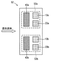
図4は、別のセンサチップ52を模式的に示した上面図である。
FIG. 4 is a top view schematically showing another
図4に示すセンサチップ52では、ヒータ素子43a、温度検出素子13aおよび容量検出素子23aからなる破線で囲った温度T1での検出素子部52aと、ヒータ素子43b、温度検出素子13bおよび容量検出素子23bからなる破線で囲った温度T2での検出素子部52bとが、混合流体の流れ方向における同じ位置に並んで配置されている。尚、図4のセンサチップ52において、ヒータ素子43aとヒータ素子43bのいずれか一方だけを形成するようにしてもよい。また、センサチップ52において、検出素子部52aと検出素子部52bは、それぞれ、基板の表側と裏側に形成するようにしてもよい。
In the
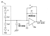
図5は、図2(a)の濃度検出装置100における誘電率測定部20の好ましい構成例を示す図で、誘電率測定部24の各部構成を示した回路ブロック図である。
FIG. 5 is a diagram showing a preferred configuration example of the dielectric
図5に示す誘電率測定部24は、直列接続された2個の容量検出素子Cs1,Cs2と帰還容量Cfが付加されたC/V変換器24aとを有している。そして、上記した混合流体の各温度における誘電率の測定においては、2個の容量検出素子Cs1,Cs2をそれぞれ図中に示した所定電圧Vの逆の搬送波FE1,FE2で駆動し、2個の容量検出素子Cs1,Cs2の接続点からの出力をC/V変換器24aに入力する。この時、C/V変換器24aの出力電圧Vsは、
(数4) Vs=V(Cs1−Cs2)/Cf
となり、2個の容量検出素子Cs1,Cs2の差分が、C/V変換される。この数式4の出力電圧Vsから、混合流体の各温度における誘電率を測定することができる。図5の誘電率測定部24を用いた誘電率測定によれば、配線による寄生容量Ceの影響をキャンセルできるため、1個の容量検出素子を用いる場合に較べてより高精度な誘電率測定が可能であり、各成分の濃度もより高精度に検出することができる。
The dielectric
(Expression 4) Vs = V (Cs1-Cs2) / Cf
Thus, the difference between the two capacitance detection elements Cs1, Cs2 is C / V converted. From the output voltage Vs of Equation 4, the dielectric constant at each temperature of the mixed fluid can be measured. According to the dielectric constant measurement using the dielectric
図6は、図5に示す2個の容量検出素子Cs1,Cs2の構成例を示した図で、容量検出素子24bを模式的に示した上面図である。
FIG. 6 is a diagram illustrating a configuration example of the two capacitance detection elements Cs1 and Cs2 illustrated in FIG. 5, and is a top view schematically illustrating the
図6に示す容量検出素子24bは、パッド4aを有する櫛歯状の電極3a、パッド4bを有する櫛歯状の電極3b、およびパッド4c,4dを有する櫛歯状の電極3cで構成されている。図6の容量検出素子24bでは、電極3aと電極3cが対をなしており、図5の容量検出素子Cs1に相当して、パッド4aに搬送波FE1が入力される。また、電極3bと電極3cが対をなしており、図5の容量検出素子Cs2に相当して、パッド4bに搬送波FE2が入力される。図6の容量検出素子24bでは、パッド4cまたはパッド4dから取り出される出力が、図5の出力C/V変換器24aに入力される。
6 includes a comb-
尚、図6の容量検出素子24bにおいては、パッド4c,4dを有する電極3cを測温抵抗体で構成し、電極3cが温度検出素子を兼ねるようにしてもよい。このように、誘電率測定部の構成要素である容量検出素子が、一対の電極からなる場合には、該電極の一方が、温度測定部の構成要素である温度検出素子を兼ねる構成とすることで、さらなる小型化とコストダウンが可能である。
In the
図7(a),(b)は、図2(a)の濃度検出装置100におけるセンサ部の別の構成例で、それぞれ、センサ部品61,62を模式的に示した断面図である。
FIGS. 7A and 7B are other configuration examples of the sensor unit in the
前述した図2(a)の濃度検出装置100におけるセンサ部の構成例は、センサチップ50〜52で、混合流体に浸漬して使用するものであった。一方、図7(a),(b)に示すセンサ部品61,62は、配管70に取り付けて使用する。図7(a)に示すセンサ部品61は、対をなす平板状の電極6a,6bと、温度検出素子である熱電対6cを備えている。また、図7(b)に示すセンサ部品62は、対をなす円筒状の電極7a,7bと、温度検出素子である熱電対7cを備えている。
The configuration example of the sensor unit in the
尚、車両の燃料の誘電率測定を行う場合、配管70の外側もしくは内側にヒータを設置して、配管70内を通る燃料の温度を変えることができる。ヒータによる加熱部の直下、加熱部より流れの上流側、もしくは加熱部より流れの下流側のうちいずれか2箇所に、図7(a),(b)に示すようなセンサ部品61,62を設置することで、図3に示したようにヒータの温度設定を変化させることなく、各成分の濃度測定が可能となる。
When measuring the dielectric constant of fuel in a vehicle, a heater can be installed outside or inside the
図8は、図7(a),(b)に示すセンサ部品61,62のように、電極寸法の大きな容量検出素子を用いる場合に好適な構成例を示す図である。
FIG. 8 is a diagram showing a configuration example suitable for using a capacitance detection element having a large electrode size, such as the
図8に示す構成では、混合流体の上流側に配置されたヒータ素子44と、混合流体の下流側に配置された温度検出素子14および容量検出素子25との間に、混合流体の攪拌手段80が設けられている。これによれば、例えばフィン、メッシュ、フィルタ等の攪拌手段80により、ヒータ素子44を用いた加熱による混合流体の温度ムラを解消して、混合流体の温度と誘電率をより正確に測定することができる。従って、図8に示す構成では、混合流体の各成分の濃度を、より正確に検出することができる。特に、図7(a),(b)に示すセンサ部品61,62のように、電極寸法の大きな容量検出素子の場合には、電極間の混合流体の体積が大きいことから、攪拌手段80を用いて電極間の混合流体の温度を均一にする必要がある。
In the configuration shown in FIG. 8, the mixed fluid agitating means 80 is provided between the
以上に示したようなセンサ部を用いて、例えば3種類の成分A,B,Cからなる混合流体の誘電率を2点の異なる温度で測定し、図2(a)に示した濃度演算部30で数式1〜3に示した連立方程式を解くことにより、各成分A,B,Cの濃度a,b,cを算出することができる。尚、N(≧3の整数)種の成分からなる混合流体の場合も、(N−1)点の異なる温度で混合流体の誘電率を測定し、数式1〜3を前述したように一般化して、各成分の濃度(存在割合)をa1,a2,・・・,aNを算出することができる。
Using the sensor unit as described above, for example, the dielectric constant of a mixed fluid composed of three types of components A, B, and C is measured at two different temperatures, and the concentration calculation unit shown in FIG. By solving the simultaneous equations shown in
以上のようにして、上記した混合流体の濃度検出方法および検出装置は、N(≧3の整数)種の既知の成分で構成される混合流体の各成分の濃度を検出する混合流体の濃度検出方法および検出装置であって、3種以上の成分で構成される混合流体の濃度を正確に検出することのできる混合流体の濃度検出方法および検出装置となっている。 As described above, the above-described mixed fluid concentration detection method and detection device detect the concentration of each component of the mixed fluid composed of N (≧ 3) types of known components and detect the concentration of the mixed fluid. This is a method and a detection apparatus, which are a mixed fluid concentration detection method and a detection apparatus capable of accurately detecting the concentration of a mixed fluid composed of three or more components.
従って、上記した混合流体の濃度検出方法および濃度検出装置は、水が混入する可能性がある内燃機関の混合燃料の濃度検出に好適であり、例えば前記成分が、エタノール、ガソリンおよび水である場合、あるいは前記成分が、脂肪酸メチルエステル、軽油および水である場合に好適である。 Therefore, the above-described mixed fluid concentration detection method and concentration detection device are suitable for detecting the concentration of the mixed fuel of an internal combustion engine in which water may be mixed. For example, the components are ethanol, gasoline, and water. Alternatively, it is suitable when the components are fatty acid methyl ester, light oil and water.
100 濃度検出装置
10 温度測定部
11,12a,12b,13a,13b 温度検出素子
20,24 誘電率測定部
21,21a,22a,22b,23a,23b 容量検出素子
30 濃度演算部
40 ヒータ部
41,42,43a,43b ヒータ素子
50〜52 センサチップ
61,62 センサ部品
70 配管
80 攪拌手段
DESCRIPTION OF
Claims (17)
(N−1)点の異なる温度で前記混合流体の誘電率を測定し、
前記(N−1)点の各温度における既知の各成分の誘電率と、前記(N−1)点の各温度で測定された前記混合流体の誘電率とから、前記各成分の濃度を算出することを特徴とする混合流体の濃度検出方法。 A mixed fluid concentration detection method for detecting the concentration of each component of a mixed fluid composed of N (> 3 integer) known components,
(N-1) Measure the dielectric constant of the mixed fluid at different temperatures.
The concentration of each component is calculated from the dielectric constant of each known component at each temperature at the (N-1) point and the dielectric constant of the mixed fluid measured at each temperature at the (N-1) point. A method for detecting the concentration of a mixed fluid, comprising:
前記各成分の濃度をそれぞれa,b,cとし、前記2点の異なる温度をそれぞれT1,T2とし、前記温度T1における各成分の誘電率をそれぞれεa1,εb1,εc1とし、前記温度T2における各成分の誘電率をそれぞれεa2,εb2,εc2とし、前記温度T1と温度T2における混合流体の誘電率をそれぞれε1,ε2としたとき、
(数1) a+b+c=1
(数2) ε1=εa1・a+εb1・b+εc1・c
(数3) ε2=εa2・a+εb2・b+εc2・c
から、前記各成分の濃度を算出することを特徴とする請求項1に記載の混合流体の濃度検出方法。 N is 3,
The concentrations of the components are a, b and c, the two different temperatures are T 1 and T 2 , respectively, and the dielectric constants of the components at the temperature T 1 are ε a1 , ε b1 and ε c1 , respectively. , When the dielectric constants of the components at the temperature T 2 are ε a2 , ε b2 , and ε c2 , respectively, and the dielectric constants of the mixed fluid at the temperature T 1 and the temperature T 2 are ε 1 and ε 2 , respectively.
(Formula 1) a + b + c = 1
(Equation 2) ε 1 = ε a1 · a + ε b1 · b + ε c1 · c
(Equation 3) ε 2 = ε a2 · a + ε b2 · b + ε c2 · c
The concentration detection method for a mixed fluid according to claim 1, wherein the concentration of each component is calculated from:
直列接続された2個の容量検出素子を所定電圧の逆の搬送波で駆動し、前記2個の容量検出素子の接続点からの出力を帰還容量が付加されたC/V変換器に入力し、該C/V変換器の出力電圧から前記混合流体の各温度における誘電率を測定することを特徴とする請求項1乃至4のいずれか一項に記載の混合流体の濃度検出方法。 In measuring the dielectric constant at each temperature of the mixed fluid,
Two capacitance detection elements connected in series are driven by a carrier wave having a reverse voltage, and an output from a connection point of the two capacitance detection elements is input to a C / V converter to which a feedback capacitance is added. 5. The mixed fluid concentration detection method according to claim 1, wherein a dielectric constant at each temperature of the mixed fluid is measured from an output voltage of the C / V converter.
前記混合流体の温度を異なる(N−1)点で測定可能な温度測定部と、
前記(N−1)点の異なる温度で前記混合流体の誘電率を測定可能な誘電率測定部と、
メモリに保存された前記(N−1)点の各温度における既知の各成分の誘電率と、前記(N−1)点の異なる温度で測定された前記混合流体の誘電率とから、前記各成分の濃度を算出する濃度演算部とを有してなることを特徴とする混合流体の濃度検出装置。 A mixed fluid concentration detection device that detects the concentration of each component of a mixed fluid composed of N (> 3 integer) known components,
A temperature measuring unit capable of measuring the temperature of the mixed fluid at different (N-1) points;
A dielectric constant measuring unit capable of measuring the dielectric constant of the mixed fluid at different temperatures of the (N-1) points;
From the dielectric constant of each known component at each temperature of the (N-1) point stored in the memory and the dielectric constant of the mixed fluid measured at different temperatures of the (N-1) point, A mixed fluid concentration detection device comprising a concentration calculation unit for calculating a concentration of a component.
前記混合流体の前記(N−1)点の異なる温度を形成するためのヒータ部を有してなることを特徴とする請求項6に記載の混合流体の濃度検出装置。 The concentration detector is
The mixed fluid concentration detection device according to claim 6, further comprising a heater unit for forming different temperatures of the (N−1) points of the mixed fluid.
前記ヒータ素子と前記温度検出素子および前記容量検出素子を熱的に分離するように、溝部が形成されてなることを特徴とする請求項9に記載の混合流体の濃度検出装置。 In the chip,
The mixed fluid concentration detection device according to claim 9, wherein a groove is formed so as to thermally separate the heater element, the temperature detection element, and the capacitance detection element.
前記混合流体の攪拌手段が設けられてなることを特徴とする請求項7に記載の混合流体の濃度検出装置。 A heater element that is a component of the heater unit arranged on the upstream side of the mixed fluid, a temperature detection element that is a component of the temperature measuring unit arranged on the downstream side of the mixed fluid, and the dielectric constant measurement unit Between the capacitance detection element that is a component of
8. The mixed fluid concentration detection device according to claim 7, further comprising stirring means for the mixed fluid.
該電極の一方が、前記温度測定部の構成要素である温度検出素子を兼ねることを特徴とする請求項6乃至12のいずれか一項に記載の混合流体の濃度検出装置。 The capacitance detection element that is a component of the dielectric constant measurement unit is composed of a pair of electrodes,
13. The mixed fluid concentration detection device according to claim 6, wherein one of the electrodes also serves as a temperature detection element that is a component of the temperature measurement unit.
直列接続された2個の容量検出素子と帰還容量が付加されたC/V変換器とを有してなり、
前記混合流体の各温度における誘電率の測定において、
前記2個の容量検出素子を所定電圧の逆の搬送波で駆動し、前記2個の容量検出素子の接続点からの出力を前記C/V変換器に入力し、該C/V変換器の出力電圧から前記混合流体の各温度における誘電率を測定することを特徴とする請求項6乃至13のいずれか一項に記載の混合流体の濃度検出装置。 The dielectric constant measuring unit is
Comprising two capacitance detection elements connected in series and a C / V converter to which a feedback capacitance is added;
In measuring the dielectric constant at each temperature of the mixed fluid,
The two capacitance detection elements are driven by a carrier wave having a predetermined voltage and the output from the connection point of the two capacitance detection elements is input to the C / V converter. The output of the C / V converter 14. The mixed fluid concentration detection device according to claim 6, wherein a dielectric constant at each temperature of the mixed fluid is measured from a voltage.
前記濃度演算部が、
前記各成分の濃度をそれぞれa,b,cとし、前記2点の異なる温度をそれぞれT1,T2とし、前記温度T1における各成分の誘電率をそれぞれεa1,εb1,εc1とし、前記温度T2における各成分の誘電率をそれぞれεa2,εb2,εc2とし、前記温度T1と温度T2における混合流体の誘電率をそれぞれε1,ε2としたとき、
(数1) a+b+c=1
(数2) ε1=εa1・a+εb1・b+εc1・c
(数3) ε2=εa2・a+εb2・b+εc2・c
から、前記各成分の濃度を算出することを特徴とする請求項6乃至14のいずれか一項に記載の混合流体の濃度検出装置。 N is 3,
The concentration calculator is
The concentrations of the components are a, b and c, the two different temperatures are T 1 and T 2 , respectively, and the dielectric constants of the components at the temperature T 1 are ε a1 , ε b1 and ε c1 , respectively. , When the dielectric constants of the components at the temperature T 2 are ε a2 , ε b2 , and ε c2 , respectively, and the dielectric constants of the mixed fluid at the temperature T 1 and the temperature T 2 are ε 1 and ε 2 , respectively.
(Formula 1) a + b + c = 1
(Equation 2) ε 1 = ε a1 · a + ε b1 · b + ε c1 · c
(Equation 3) ε 2 = ε a2 · a + ε b2 · b + ε c2 · c
The concentration detection device for a mixed fluid according to claim 6, wherein the concentration of each component is calculated from the above.
Priority Applications (4)
| Application Number | Priority Date | Filing Date | Title |
|---|---|---|---|
| JP2009054056A JP5056776B2 (en) | 2009-03-06 | 2009-03-06 | Concentration detection method and detection apparatus for mixed fluid |
| US12/733,694 US8578761B2 (en) | 2008-03-26 | 2009-03-25 | Concentration sensor device and concentration detecting method |
| BRPI0907020-6A BRPI0907020A2 (en) | 2008-03-26 | 2009-03-25 | Concentration sensing device, mixing ratio calculation device, methods for calculating mixing ratio of the mixing liquid and for detecting fluid concentrations, and concentration detection device |
| PCT/JP2009/001334 WO2009119087A1 (en) | 2008-03-26 | 2009-03-25 | Concentration sensor device and concentration detection method |
Applications Claiming Priority (1)
| Application Number | Priority Date | Filing Date | Title |
|---|---|---|---|
| JP2009054056A JP5056776B2 (en) | 2009-03-06 | 2009-03-06 | Concentration detection method and detection apparatus for mixed fluid |
Publications (2)
| Publication Number | Publication Date |
|---|---|
| JP2010210285A true JP2010210285A (en) | 2010-09-24 |
| JP5056776B2 JP5056776B2 (en) | 2012-10-24 |
Family
ID=42970626
Family Applications (1)
| Application Number | Title | Priority Date | Filing Date |
|---|---|---|---|
| JP2009054056A Expired - Fee Related JP5056776B2 (en) | 2008-03-26 | 2009-03-06 | Concentration detection method and detection apparatus for mixed fluid |
Country Status (1)
| Country | Link |
|---|---|
| JP (1) | JP5056776B2 (en) |
Cited By (4)
| Publication number | Priority date | Publication date | Assignee | Title |
|---|---|---|---|---|
| JP2015500470A (en) * | 2011-11-30 | 2015-01-05 | ゼネラル・エレクトリック・カンパニイ | High-level current measurement techniques for multiphase fluids. |
| JP2015169179A (en) * | 2014-03-10 | 2015-09-28 | 愛三工業株式会社 | sensor device |
| WO2017086214A1 (en) * | 2015-11-16 | 2017-05-26 | ナブテスコ株式会社 | Sensor device |
| JP2017535766A (en) * | 2014-10-07 | 2017-11-30 | ベルキン ビーブイBerkin B.V. | Method for determining the proportion of a flowing gaseous medium and system for use therewith |
Citations (6)
| Publication number | Priority date | Publication date | Assignee | Title |
|---|---|---|---|---|
| JPS56148047A (en) * | 1980-04-18 | 1981-11-17 | Koumiyou Rikagaku Kogyo Kk | Thermal conductivity type gas detector |
| JPS59131154A (en) * | 1983-01-14 | 1984-07-27 | Komatsu Ltd | Dielectric constant measuring sensor |
| JPH08201326A (en) * | 1995-01-30 | 1996-08-09 | Gastar Corp | Exhaust co concentration detecting device for combustion apparatus |
| JP2571465B2 (en) * | 1990-10-17 | 1997-01-16 | 株式会社ユニシアジェックス | Gasoline property identification device |
| JP2004125465A (en) * | 2002-09-30 | 2004-04-22 | Mitsui Mining & Smelting Co Ltd | Gasoline type identification device, and gasoline type identification method |
| JP2005201670A (en) * | 2004-01-13 | 2005-07-28 | Mitsui Mining & Smelting Co Ltd | Alcohol concentration sensor and alcohol concentration measuring instrument |
-
2009
- 2009-03-06 JP JP2009054056A patent/JP5056776B2/en not_active Expired - Fee Related
Patent Citations (6)
| Publication number | Priority date | Publication date | Assignee | Title |
|---|---|---|---|---|
| JPS56148047A (en) * | 1980-04-18 | 1981-11-17 | Koumiyou Rikagaku Kogyo Kk | Thermal conductivity type gas detector |
| JPS59131154A (en) * | 1983-01-14 | 1984-07-27 | Komatsu Ltd | Dielectric constant measuring sensor |
| JP2571465B2 (en) * | 1990-10-17 | 1997-01-16 | 株式会社ユニシアジェックス | Gasoline property identification device |
| JPH08201326A (en) * | 1995-01-30 | 1996-08-09 | Gastar Corp | Exhaust co concentration detecting device for combustion apparatus |
| JP2004125465A (en) * | 2002-09-30 | 2004-04-22 | Mitsui Mining & Smelting Co Ltd | Gasoline type identification device, and gasoline type identification method |
| JP2005201670A (en) * | 2004-01-13 | 2005-07-28 | Mitsui Mining & Smelting Co Ltd | Alcohol concentration sensor and alcohol concentration measuring instrument |
Cited By (5)
| Publication number | Priority date | Publication date | Assignee | Title |
|---|---|---|---|---|
| JP2015500470A (en) * | 2011-11-30 | 2015-01-05 | ゼネラル・エレクトリック・カンパニイ | High-level current measurement techniques for multiphase fluids. |
| JP2015169179A (en) * | 2014-03-10 | 2015-09-28 | 愛三工業株式会社 | sensor device |
| JP2017535766A (en) * | 2014-10-07 | 2017-11-30 | ベルキン ビーブイBerkin B.V. | Method for determining the proportion of a flowing gaseous medium and system for use therewith |
| WO2017086214A1 (en) * | 2015-11-16 | 2017-05-26 | ナブテスコ株式会社 | Sensor device |
| JPWO2017086214A1 (en) * | 2015-11-16 | 2018-08-23 | ナブテスコ株式会社 | Sensor device |
Also Published As
| Publication number | Publication date |
|---|---|
| JP5056776B2 (en) | 2012-10-24 |
Similar Documents
| Publication | Publication Date | Title |
|---|---|---|
| US8578761B2 (en) | Concentration sensor device and concentration detecting method | |
| Papathanasiou et al. | Illuminating the connection between contact angle saturation and dielectric breakdown in electrowetting through leakage current measurements | |
| US20100264900A1 (en) | Multifunctional Potentiometric Gas Sensor Array With an Integrated Temperature Control and Temperature Sensors | |
| JP5056776B2 (en) | Concentration detection method and detection apparatus for mixed fluid | |
| US7692432B2 (en) | Liquid property sensor | |
| Goel et al. | Rapid and automated measurement of biofuel blending using a microfluidic viscometer | |
| Gauthier et al. | Gas thermal conductivity measurement using the three-omega method | |
| US8950273B2 (en) | Method and thermal, flow measuring device for determining and/or monitoring at least one variable dependent on at least the chemical composition of a measured medium | |
| Roh et al. | Sensitivity enhancement of a silicon micro-machined thermal flow sensor | |
| Agostini et al. | Effects of geometrical and thermophysical parameters on heat transfer measurements in small-diameter channels | |
| Zhang et al. | The density, viscosity, speed of sound, excess properties of binary mixtures of linear polydimethylsiloxane and various alkanes at temperatures in the range (288.15–328.15) K | |
| Lötters et al. | Fully integrated microfluidic measurement system for real-time determination of gas and liquid mixtures composition | |
| Alanazi et al. | New non-invasive thermal sensor design for a pipe flow | |
| Huang et al. | Electrical impedance characteristics of slug flow in small channels and its application to void fraction estimation | |
| Bernhardsgrütter et al. | Towards a robust thin film sensor for distinguishing fluids using the 3ω-method | |
| Liu et al. | Flow and heat transfer in rough micro steel tubes | |
| RU2330270C2 (en) | Device and calculation method of thermal resistivity | |
| Kuvshinov et al. | Thermal conductivity measurement of liquids in a microfluidic device | |
| Hong et al. | Measuring the thermal conductivity of flowing liquid samples using the three omega method | |
| CN102636524A (en) | Device for electrically transiently measuring thermo-physical properties of materials and method | |
| Venkateswaran et al. | Computational analysis of a microfluidic viscometer and its application in the rapid and automated measurement of biodiesel blending under pressure driven flow | |
| CN114100708B (en) | Microfluid concentration sensing chip and microfluid characteristic measuring device | |
| RU59831U1 (en) | DEVICE FOR MEASURING HEAT VALUES | |
| Bernhardsgrütter et al. | Fluid-compensated thermal flow sensor: A combination of the 3ω-method and constant temperature anemometry | |
| Ghaderi et al. | MEMS for biofuel composition measurement based on thermal impedance spectroscopy |
Legal Events
| Date | Code | Title | Description |
|---|---|---|---|
| A131 | Notification of reasons for refusal |
Free format text: JAPANESE INTERMEDIATE CODE: A131 Effective date: 20120417 |
|
| A521 | Written amendment |
Free format text: JAPANESE INTERMEDIATE CODE: A523 Effective date: 20120611 |
|
| TRDD | Decision of grant or rejection written | ||
| A01 | Written decision to grant a patent or to grant a registration (utility model) |
Free format text: JAPANESE INTERMEDIATE CODE: A01 Effective date: 20120703 |
|
| A01 | Written decision to grant a patent or to grant a registration (utility model) |
Free format text: JAPANESE INTERMEDIATE CODE: A01 |
|
| A61 | First payment of annual fees (during grant procedure) |
Free format text: JAPANESE INTERMEDIATE CODE: A61 Effective date: 20120716 |
|
| FPAY | Renewal fee payment (event date is renewal date of database) |
Free format text: PAYMENT UNTIL: 20150810 Year of fee payment: 3 |
|
| FPAY | Renewal fee payment (event date is renewal date of database) |
Free format text: PAYMENT UNTIL: 20150810 Year of fee payment: 3 |
|
| R250 | Receipt of annual fees |
Free format text: JAPANESE INTERMEDIATE CODE: R250 |
|
| R250 | Receipt of annual fees |
Free format text: JAPANESE INTERMEDIATE CODE: R250 |
|
| R250 | Receipt of annual fees |
Free format text: JAPANESE INTERMEDIATE CODE: R250 |
|
| LAPS | Cancellation because of no payment of annual fees |