JP2010208367A - Pneumatic tire - Google Patents
Pneumatic tire Download PDFInfo
- Publication number
- JP2010208367A JP2010208367A JP2009053757A JP2009053757A JP2010208367A JP 2010208367 A JP2010208367 A JP 2010208367A JP 2009053757 A JP2009053757 A JP 2009053757A JP 2009053757 A JP2009053757 A JP 2009053757A JP 2010208367 A JP2010208367 A JP 2010208367A
- Authority
- JP
- Japan
- Prior art keywords
- layer
- peripheral side
- reinforcing layer
- tire
- belt
- Prior art date
- Legal status (The legal status is an assumption and is not a legal conclusion. Google has not performed a legal analysis and makes no representation as to the accuracy of the status listed.)
- Granted
Links
- 239000000463 material Substances 0.000 claims abstract description 36
- 230000002787 reinforcement Effects 0.000 claims abstract description 19
- 239000011324 bead Substances 0.000 claims abstract description 10
- 230000002093 peripheral effect Effects 0.000 claims description 72
- 230000003014 reinforcing effect Effects 0.000 claims description 69
- 238000010073 coating (rubber) Methods 0.000 claims description 2
- 230000000052 comparative effect Effects 0.000 description 8
- 230000001965 increasing effect Effects 0.000 description 8
- 230000000694 effects Effects 0.000 description 5
- 239000004677 Nylon Substances 0.000 description 4
- 229920001778 nylon Polymers 0.000 description 4
- 238000000926 separation method Methods 0.000 description 4
- 229910000831 Steel Inorganic materials 0.000 description 3
- 239000004760 aramid Substances 0.000 description 3
- 229920003235 aromatic polyamide Polymers 0.000 description 3
- 238000011156 evaluation Methods 0.000 description 3
- 230000033001 locomotion Effects 0.000 description 3
- 239000010959 steel Substances 0.000 description 3
- 238000010586 diagram Methods 0.000 description 2
- 229920000728 polyester Polymers 0.000 description 2
- 229920000297 Rayon Polymers 0.000 description 1
- 230000002301 combined effect Effects 0.000 description 1
- 230000002708 enhancing effect Effects 0.000 description 1
- 239000000835 fiber Substances 0.000 description 1
- 239000003365 glass fiber Substances 0.000 description 1
- 238000004519 manufacturing process Methods 0.000 description 1
- 238000000034 method Methods 0.000 description 1
- 238000011056 performance test Methods 0.000 description 1
- 229920003207 poly(ethylene-2,6-naphthalate) Polymers 0.000 description 1
- 229920000139 polyethylene terephthalate Polymers 0.000 description 1
- 239000002964 rayon Substances 0.000 description 1
- 230000001953 sensory effect Effects 0.000 description 1
Images

Landscapes
- Tires In General (AREA)
Abstract
Description
本発明は、一対のビード部の間に配設されたカーカス層と、そのカーカス層のトレッド部外周に積層されたベルト層と、を備える空気入りタイヤに関する。 The present invention relates to a pneumatic tire including a carcass layer disposed between a pair of bead portions and a belt layer laminated on the outer periphery of a tread portion of the carcass layer.
一般に、運動性能の高い車両に装着されるタイヤでは、高速走行における耐久性(高速耐久性)だけでなく、制動性や操縦安定性についても高い水準が要求される。下記特許文献1では、高速耐久性を維持しながら操縦安定性を向上させることを目的として、ベルト層の幅方向端部のうち車両に対する装着内側となる端部のみを、補強層で包み込んで補強した空気入りラジアルタイヤが提案されている。
In general, a tire mounted on a vehicle having high motion performance is required to have a high level not only for durability at high speed (high speed durability) but also for braking performance and steering stability. In
上記のタイヤ構造は、空気入りラジアルタイヤが基本的にはネガティブキャンバーにて車両に装着されることを考慮して、タイヤの装着内側と装着外側とでそれぞれ要求される仕様を満たすもの、として説明されている。つまり、タイヤの装着内側では、高荷重が作用して接地圧が高くなることから、ベルト層の端部を補強して高速耐久性の確保を図っている。一方、タイヤの装着外側では、補強層を設けないことにより旋回時の接地性を高め、操縦安定性の向上を図っている。 The above tire structure is described as satisfying the specifications required for the inside and the outside of the tire, considering that the pneumatic radial tire is basically attached to the vehicle with a negative camber. Has been. In other words, since a high load acts on the inner side of the tire and the ground pressure increases, the end of the belt layer is reinforced to ensure high-speed durability. On the other hand, on the outer side of the tire, the grounding property at the time of turning is improved by not providing a reinforcing layer, and the steering stability is improved.
しかし、実用上、タイヤのキャンバー角は種々の大きさで設定され、ネガティブキャンバーであってもキャンバー角が小さい場合には、セパレーション等の故障がベルト層の装着外側の端部から発生することもあり得るため、ベルト層の装着内側に対する補強のみでは、高速耐久性を高い水準で確保できない恐れがある。また、ベルト層の装着内側に対する補強のみでは、タイヤの剛性バランスが大きく崩れるため、操縦安定性を十分に向上できないことが懸念される。更に、ベルト層の装着内側に配設される補強層においては、その簡単な形状変更によって制動性能を更に改良できる見込みがあることが分かった。 However, for practical purposes, the tire camber angle is set in various sizes, and even if it is a negative camber, if the camber angle is small, a failure such as separation may occur from the outer end of the belt layer. Therefore, there is a possibility that high-speed durability cannot be secured at a high level only by reinforcing the inner side of the belt layer. In addition, there is a concern that the steering stability cannot be sufficiently improved because only the reinforcement on the inner side of the belt layer significantly collapses the rigidity balance of the tire. Further, it has been found that the braking performance of the reinforcing layer disposed on the inner side of the belt layer can be further improved by a simple shape change.
本発明は上記実情に鑑みてなされたものであり、その目的は、タイヤの剛性バランスを大きく崩すことなく、高速耐久性を高い水準で維持しながら、制動性能と操縦安定性能を向上させた空気入りタイヤを提供することにある。 The present invention has been made in view of the above circumstances, and an object of the present invention is to improve braking performance and steering stability performance while maintaining high-speed durability at a high level without greatly losing the rigidity balance of the tire. The purpose is to provide tires.
上記目的は、下記の如き本発明により達成できる。即ち、本発明の空気入りタイヤは、一対のビード部の間に配設されたカーカス層と、前記カーカス層のトレッド部外周に積層されたベルト層と、を備える空気入りタイヤにおいて、前記ベルト層の車両に対する装着内側の端部を包み込むように、前記ベルト層の内周側から外周側に折り返され、その内周側部分を外周側部分よりも幅広とした内側補強層と、前記ベルト層の車両に対する装着外側の端部を包み込むように、前記ベルト層の内周側から外周側に折り返された外側補強層とを備え、前記内側補強層と前記外側補強層とが、配列した多数のコード材をゴム被覆して形成された部材であり、前記外側補強層のコード材を前記内側補強層のコード材よりも低モジュラスとしたものである。 The above object can be achieved by the present invention as described below. That is, the pneumatic tire of the present invention is a pneumatic tire comprising a carcass layer disposed between a pair of bead portions, and a belt layer laminated on an outer periphery of a tread portion of the carcass layer. An inner reinforcement layer that is folded from the inner peripheral side of the belt layer to the outer peripheral side so as to wrap the inner end portion of the belt layer attached to the vehicle, the inner peripheral side portion being wider than the outer peripheral side portion, and the belt layer A plurality of cords including an outer reinforcing layer folded from an inner peripheral side of the belt layer to an outer peripheral side so as to wrap an outer end portion of the belt mounted on the vehicle, wherein the inner reinforcing layer and the outer reinforcing layer are arranged. It is a member formed by covering a material with rubber, and the cord material of the outer reinforcing layer has a lower modulus than the cord material of the inner reinforcing layer.
本発明に係る空気入りタイヤでは、ベルト層の両端部を補強層により包み込んで補強していることから、タイヤの剛性バランスを大きく崩すことがなく、たとえキャンバー角が小さい場合であっても、高速耐久性を高い水準で維持することができる。即ち、高速走行時にはベルト層の端部に大きな歪みが生じてセパレーション等の故障が発生し易いところ、本発明では、ベルト層の両端部を補強層で包み込んで補強してあることにより、高速耐久性を適切に確保することができる。 In the pneumatic tire according to the present invention, since both ends of the belt layer are wrapped and reinforced by the reinforcing layer, the rigidity balance of the tire is not greatly lost, and even if the camber angle is small, high speed Durability can be maintained at a high level. In other words, when the belt is running at high speed, the end of the belt layer is greatly distorted, and a failure such as separation is likely to occur. In the present invention, both ends of the belt layer are wrapped and reinforced, so that high speed durability is achieved. Sex can be secured appropriately.
しかも、本発明の空気入りタイヤでは、内側補強層の内周側部分が外周側部分よりも幅広であるため、直進時における接地長が長く制動性への影響が大きい装着内側において、補強層とカーカス層との接触面積が増大する。このため、制動時のカーカス層の動きを拘束し易く、タイヤの周方向剛性を高めて制動性能を向上できる。それでいて、外側補強層のコード材が内側補強層のコード材よりも低モジュラスであることにより、旋回時にはタイヤの装着外側の接地長を円滑に延ばしてグリップ性能を向上できる。それ故、ベルト層の装着外側の端部を補強しながらも、操縦安定性が効果的に高められる。 Moreover, in the pneumatic tire of the present invention, since the inner peripheral side portion of the inner reinforcing layer is wider than the outer peripheral side portion, the inner surface of the mounting layer has a longer ground contact length when traveling straight and has a great influence on braking performance. The contact area with the carcass layer increases. For this reason, it is easy to restrain the movement of the carcass layer during braking, and it is possible to improve the braking performance by increasing the circumferential rigidity of the tire. Nevertheless, since the cord material of the outer reinforcing layer has a lower modulus than the cord material of the inner reinforcing layer, the ground contact length on the outer side of the tire can be smoothly extended during turning, thereby improving the grip performance. Therefore, the steering stability is effectively enhanced while reinforcing the outer end of the belt layer.
上記において、前記外側補強層の外周側部分を内周側部分よりも幅広としたものが好ましい。本発明では、外側補強層のコード材のモジュラスが比較的低いため、タイヤの装着外側における剛性が装着内側よりも低くなる傾向にあるが、上記構成によれば、外側補強層の外周側部分が内周側部分よりも幅広であることにより、タイヤの装着外側のトレッド面の剛性を高めて、タイヤの剛性バランスを改善して操縦安定性を向上できる。 In the above, it is preferable that the outer peripheral portion of the outer reinforcing layer is wider than the inner peripheral portion. In the present invention, since the modulus of the cord material of the outer reinforcing layer is relatively low, the rigidity on the outer side of the tire tends to be lower than that on the inner side of the tire. By being wider than the inner peripheral side portion, the rigidity of the tread surface on the outer side of the tire can be increased, and the rigidity balance of the tire can be improved to improve the steering stability.
本発明の空気入りタイヤが備えるトレッドパターンは、特に限られるものではないが、トレッド面の装着外側の溝面積が装着内側の溝面積よりも小さい非対称のトレッドパターンを備えるものでもよい。かかる場合には、トレッド面の装着外側での剛性が高められることから、特に外側補強層の外周側部分を内周側部分よりも幅広とした場合には、それによる作用効果とも相俟って、タイヤの剛性バランスをより良好に改善できる。 The tread pattern included in the pneumatic tire of the present invention is not particularly limited, but may include an asymmetric tread pattern in which the groove area on the outer side of the tread surface is smaller than the groove area on the inner side of the mounting. In such a case, since the rigidity on the outer side of the tread surface is enhanced, especially when the outer peripheral side portion of the outer reinforcing layer is wider than the inner peripheral side portion, it is combined with the function and effect thereof. The tire rigidity balance can be improved more favorably.
本発明では、前記内側補強層の外周側部分及び前記外側補強層の外周側部分が、それぞれ主溝の内周側を通過せずに終端するものが好ましい。かかる構成によれば、主溝の底側におけるトレッドゴムの厚みを確保して、高速耐久性を確保することができる。 In the present invention, it is preferable that the outer peripheral side portion of the inner reinforcing layer and the outer peripheral side portion of the outer reinforcing layer terminate without passing through the inner peripheral side of the main groove. According to such a configuration, the thickness of the tread rubber on the bottom side of the main groove can be ensured to ensure high-speed durability.
本発明の実施の形態について、図面を参照しながら説明する。図1は、本発明に係る空気入りタイヤの一例を概略的に示すタイヤ子午線断面図である。このタイヤTは、車両への装着方向が指定されたタイヤであり、図1左側が車両に対する装着内側、図1右側が車両に対する装着外側となる。即ち、このタイヤTが車両に装着された状態では、図1左側が車両の内側に配されることになる。 Embodiments of the present invention will be described with reference to the drawings. FIG. 1 is a tire meridian cross-sectional view schematically showing an example of a pneumatic tire according to the present invention. The tire T is a tire in which the mounting direction to the vehicle is designated, and the left side in FIG. 1 is the mounting inner side with respect to the vehicle, and the right side in FIG. That is, when the tire T is mounted on the vehicle, the left side in FIG. 1 is arranged inside the vehicle.
タイヤTは、一対のビード部1と、ビード部1からタイヤ径方向外側に延びるサイドウォール部2と、そのサイドウォール部2の各々のタイヤ径方向外側端に連なるトレッド部3と、一対のビード部1の間でトロイド状に延びるカーカス層4とを備える空気入りラジアルタイヤである。カーカス層4は、ビード部1に配設された環状のビードコア1aを介して、端部を巻き上げられている。
The tire T includes a pair of
カーカス層4は、タイヤ赤道Cに対して略90°の角度で配列した多数のコード材をゴム被覆してなるカーカスプライからなる。本実施形態では、1枚のカーカスプライによって1層のカーカス層4を形成した例を示すが、これを2層以上にすることも可能である。カーカス層4を構成するコード材としては、ポリエステルやレーヨン、ナイロン、アラミド等の有機繊維コードが好ましく採用される。 The carcass layer 4 is made of a carcass ply formed by rubber-coating a large number of cord materials arranged at an angle of approximately 90 ° with respect to the tire equator C. In the present embodiment, an example in which one carcass layer 4 is formed by one carcass ply is shown, but it is also possible to have two or more layers. As the cord material constituting the carcass layer 4, organic fiber cords such as polyester, rayon, nylon, and aramid are preferably employed.
カーカス層4のトレッド部3外周には、たが効果によりカーカス層4を補強するベルト層6が積層されている。ベルト層6は、内外に積層された2枚のベルトプライ6a,6bにより構成されている。ベルトプライ6a,6bは、タイヤ赤道Cに対して所定の角度で傾斜して延びるコード材をゴム被覆して形成され、該コード材がプライ間で互いに逆向きに交差するように配設される。ベルト層6を構成するコード材としては、スチールが好ましく採用される。
On the outer periphery of the
ベルト層6の外周側にはトレッドゴム5が配設され、そのトレッド面には、タイヤ周方向に沿って延びる複数の主溝7〜9と、それらに交差して延びる複数の横溝(図示せず)が設けられ、要求されるタイヤ性能や使用条件に応じたトレッドパターンが形成されている。具体的なパターン形状は図示していないが、本実施形態のタイヤTは、タイヤ赤道Cを境界として、トレッド面の装着外側の溝面積が装着内側の溝面積よりも小さい、左右非対称のトレッドパターンを備える。
A
内側補強層11は、ベルト層6の装着内側の端部を包み込むように、ベルト層6の内周側から外周側に折り返されている。内側補強層11では、その内周側部分11aが外周側部分11bよりも幅広であり、内周側部分11aのタイヤ幅方向長さをWA、外周側部分11bのタイヤ幅方向長さをWBとした場合に、WA>WBの関係を満たすように設定されている。
The
他方、外側補強層12は、ベルト層6の装着外側の端部を包み込むように、ベルト層6の内周側から外周側に折り返されている。外側補強層12では、その外周側部分12bが内周側部分12aよりも幅広であり、内周側部分12aのタイヤ幅方向長さをWC、外周側部分12bのタイヤ幅方向長さをWDとした場合に、WC<WDの関係を満たすように設定されている。
On the other hand, the
内側補強層11及び外側補強層12は、いずれも配列した多数のコード材をゴム被覆して形成された部材であり、タイヤ周方向に沿って環状に配設されている。本発明では、外側補強層12のコード材が、内側補強層11のコード材よりも低モジュラスである。具体的には、内側補強層11のコード材にPEN、アラミドやPOK、ガラス繊維、スチールなどを使用し、外側補強層12のコード材にポリエステルやナイロン、PET、PENなどを使用したものが例示される。なお、両補強層11,12のコード材が同じ材質であっても、コード径や撚り数などを異ならせることによりモジュラス差を創出可能である。
Each of the inner reinforcing
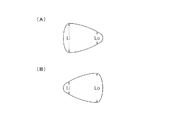
図2は、このタイヤTをネガティブキャンバーにて車両に装着したときの接地形状を示す概念図であり、(A)が直進時、(B)が旋回時を示している。図1と同様に、図2左側が車両に対する装着内側となり、図2右側が車両に対する装着外側となる。 FIGS. 2A and 2B are conceptual diagrams showing a ground contact shape when the tire T is mounted on a vehicle with a negative camber. FIG. 2A shows a straight traveling time and FIG. 2B shows a turning time. As in FIG. 1, the left side of FIG. 2 is the inner side of the vehicle and the right side of FIG. 2 is the outer side of the vehicle.
直進時には、図2(A)に示すように、キャンバー角がネガティブであることに起因して装着内側に高荷重が作用し、装着内側の接地長Liが強制的に引き延ばされた接地形状となる。かかる接地形状であると、特に高速走行時においては、ベルト層6の装着内側の端部から発生するセパレーションが心配されるが、このタイヤTでは、装着内側の端部を内側補強層11により包み込んで補強していることにより、高速耐久性が好適に確保される。
When traveling straight, as shown in FIG. 2 (A), a high load acts on the inner side due to the negative camber angle, and the ground contact length Li on the inner side is forcibly extended. It becomes. With such a ground contact shape, there is a concern about the separation that occurs from the end portion on the inner side of the
そのうえ、このタイヤTでは、ベルト層6の装着外側の端部を外側補強層12により包み込んで補強しているため、装着内側のみの補強とは違って、タイヤの剛性バランスが補強層によって大きく崩れることがない。しかも、キャンバー角が小さい場合には、ベルト層6の装着外側の端部から発生するセパレーションも懸念されるが、ベルト層6の両端部を補強していることから、高速耐久性を高い水準で維持することができる。
In addition, in this tire T, since the outer end of the
図2(A)の如き接地形状であると、タイヤの装着外側よりも装着内側の方が制動性への影響が大きい。そこで、装着内側に配される内側補強層11では、内周側部分11aを外周側部分11bよりも幅広にしている。これにより、内側補強層11とカーカス層4との接触面積を増やして、制動時のカーカス層4の動きを拘束し易くし、タイヤTの周方向剛性を高めて制動性能を向上できる。
When the ground contact shape is as shown in FIG. 2 (A), the effect on braking performance is greater on the inner side of the tire than on the outer side of the tire. Therefore, in the inner reinforcing
旋回時には、図2(B)に示すように、車両のロール運動に伴って、装着外側の接地長Loが強制的に引き延ばされた接地形状となる。かかる状態では、装着外側の接地長Loを適切に延ばしてグリップ性能を高めることが、操縦安定性を向上するうえで有利となる。そこで、装着外側に配される外側補強層12には、内側補強層11のコード材よりも低モジュラスのコード材を採用し、旋回時の接地長Loを円滑に延ばして操縦安定性を向上できるようにしている。
At the time of turning, as shown in FIG. 2 (B), the ground contact length Lo on the outer side of the mounting is forcibly extended as the vehicle rolls. In such a state, it is advantageous to improve the steering stability by appropriately extending the contact length Lo on the outside of the wearing to improve the grip performance. Therefore, a cord material having a lower modulus than the cord material of the
また、外側補強層12の外周側部分12bを内周側部分12aよりも幅広にしていることで、タイヤの装着外側のトレッド面の剛性が高められる。それ故、低モジュラスのコード材を使用することによる剛性低下を緩和して、タイヤの剛性バランスを改善できる。特に本実施形態では、上記の如き非対称パターンによってもトレッド面の装着外側での剛性が高められるため、これらの作用効果が相俟って、タイヤの剛性バランスを良好に改善できる。
Moreover, the rigidity of the tread surface on the outer side of the tire is increased by making the outer
以上のように、この空気入りタイヤTでは、補強層11,12によってベルト層6の両端部を包み込むようにした補強構造と、その補強層11,12のコード材のモジュラスを互いに相違させた非対称構造との協働により、タイヤの剛性バランスを大きく崩すことなく、高速耐久性を高い水準で維持しながら、制動性能と操縦安定性能を向上させることができる。
As described above, in this pneumatic tire T, the asymmetric structure in which the reinforcement layers 11 and 12 wrap both ends of the
内側補強層11と外側補強層12は、コード材がタイヤ周方向に対して0〜40°の角度で延びるように配設され得る。但し、ベルト層6の端部の包み込みによる補強効果を高める観点から、コード材の角度は20〜40°であることが好ましい。
The inner reinforcing
高速耐久性や制動性を良好に向上するべく、内側補強層11のコード材は、2%引張モジュラス(2%伸長時荷重)が60N以上であることが好ましい。また、旋回時の接地長Loを円滑に延ばす効果を確保する観点から、外側補強層12のコード材は、2%引張モジュラスが40N以下であることが好ましい。
In order to improve high-speed durability and braking performance satisfactorily, the cord material of the inner reinforcing
内側補強層11の内周側部分11aの長さWAは、高速耐久性及び制動性を確実に向上するべく、ベルト幅BWの10〜30%の範囲に設定されている。また、外周側部分11bの長さWBは、ベルト層6の端部の補強効果を確保するうえで、ベルト幅BWの5〜20%であることが好ましい。外周側部分11bは、主溝7〜9の内周側を通過することなく主溝7の手前で終端しているため、主溝の底側におけるトレッドゴム5の厚みを確保して高速耐久性を確保できる。
The length WA of the inner
外側補強層12の内周側部分12aの長さWCは、ベルト層6の端部の補強効果を確保するうえで、ベルト幅BWの5〜20%であることが好ましい。また、外周側部分12bの長さWDは、装着外側のトレッド面の剛性を確実に高める観点から、ベルト幅BWの10〜30%の範囲に設定されている。外周側部分12bは、主溝7〜9の内周側を通過することなく主溝9の手前で終端しており、主溝の底側におけるトレッドゴム5の厚みを確保して高速耐久性を確保できる。
The length WC of the inner
本発明の空気入りタイヤは、上記の如き内側補強層と外側補強層を配設すること以外は、通常の空気入りタイヤと同等であり、従来公知の材料、形状、構造、製法などが何れも本発明に採用することができる。 The pneumatic tire of the present invention is the same as a normal pneumatic tire except that the inner reinforcing layer and the outer reinforcing layer are disposed as described above, and all of the conventionally known materials, shapes, structures, manufacturing methods, etc. It can be employed in the present invention.
[他の実施形態]
(1)前述の実施形態では、トレッド面の装着外側の溝面積が装着内側の溝面積よりも小さい非対称のトレッドパターンを備える例を示したが、本発明の空気入りタイヤは、これ以外の非対称トレッドパターン、或いはタイヤ赤道に関して対称的なトレッドパターンを備えるものでも構わない。
[Other Embodiments]
(1) In the above-described embodiment, the example in which the groove area on the outer side of the tread surface is provided with an asymmetric tread pattern smaller than the groove area on the inner side of the mounting is shown. A tread pattern or a tread pattern symmetrical with respect to the tire equator may be provided.
(2)前述の実施形態では、外側補強層の外周側部分を内周側部分よりも幅広とした例を示したが、本発明では、この内周側部分と外周側部分とを同等の幅寸法にしてもよく、或いは内周側部分を外周側部分よりも幅広にしても構わない。 (2) In the above-described embodiment, an example in which the outer peripheral side portion of the outer reinforcing layer is wider than the inner peripheral portion has been shown. However, in the present invention, the inner peripheral portion and the outer peripheral portion have the same width. You may make it a dimension, or you may make an inner peripheral side part wider than an outer peripheral side part.
以下、本発明の構成と効果を具体的に示す実施例について説明する。実施例等における評価項目は下記のようにして測定を行った。 Examples that specifically show the structure and effects of the present invention will be described below. Evaluation items in Examples and the like were measured as follows.
(1)高速耐久性
欧州経済委員会規則第30の付則7で荷重/速度性能試験手順として定められた速度記号Wのタイヤについての条件に準拠してテストを行なった。走行速度は10分毎に10km/hずつ増分させ、タイヤが故障するまでドラム試験機にて高速走行させた。比較例1の結果を100として指数で評価し、当該指数が大きいほど高速耐久性に優れていることを示す。
(1) High-speed durability A test was conducted in accordance with the conditions for a tire having a speed symbol W determined as a load / speed performance test procedure in
(2)操縦安定性
4名のパネラーが、テストコースにおける発進、旋回、制動について総合的に官能評価した。比較例1の結果を100として指数で評価し、当該指数が大きいほど操縦安定性に優れていることを示す。
(2) Steering stability Four panelists conducted a comprehensive sensory evaluation on starting, turning and braking on the test course. The result of Comparative Example 1 was evaluated as an index with the value 100, and the larger the index, the better the steering stability.
(3)制動性
実車に装着して直進走行させ、走行速度を100km/hから0km/hに落としたときの停止距離を測定し、その逆数を算出した。比較例1の結果を100として指数で評価し、当該指数が大きいほど制動性に優れていることを示す。
(3) Braking property Attached to an actual vehicle and traveled straight, the stopping distance when the traveling speed was reduced from 100 km / h to 0 km / h was measured, and the reciprocal was calculated. The result of Comparative Example 1 was evaluated as an index with the value of 100, and the larger the index, the better the braking performance.
比較例1,2
空気入りラジアルタイヤ(サイズ:225/45R17)において、ベルト層の両端部をナイロン製のコード材で構成した補強層により包み込んで補強したものを比較例1とした。また、ベルト層の装着内側の端部のみを前記の補強層で包み込んで補強し、装着外側には補強層を配設していないものを比較例2とした。比較例1,2では、いずれも補強層の内周側部分と外周側部分との幅寸法が同等となるようにした。
Comparative Examples 1 and 2
In a pneumatic radial tire (size: 225 / 45R17), Comparative Example 1 was obtained by wrapping and reinforcing both ends of a belt layer with a reinforcing layer made of a nylon cord material. Further, only the end portion on the inner side of the belt layer attached was wrapped and reinforced with the reinforcing layer, and the reinforcing layer was not provided on the outer side of the attachment as Comparative Example 2. In Comparative Examples 1 and 2, the width dimensions of the inner peripheral side portion and the outer peripheral side portion of the reinforcing layer were made equal.
実施例1,2
空気入りラジアルタイヤ(サイズ:225/45R17)において、ベルト層の装着内側の端部をアラミド製のコード材で構成した内側補強層により包み込んで補強し、該ベルト層の装着外側の端部をナイロン製のコード材で構成した外側補強層により包み込んで補強したものを実施例1,2とした。実施例1,2では、いずれも内側補強層の内周側部分を外周側部分よりも幅広とした。また、実施例1では、外側補強層の内周側部分を外周側部分よりも幅広としたが、実施例2では、外側補強層の外周側部分を内周側部分よりも幅広とした。評価結果を表1に示す。
Examples 1 and 2
In a pneumatic radial tire (size: 225 / 45R17), the end portion on the inner side of the belt layer is wrapped and reinforced by an inner reinforcing layer made of an aramid cord material, and the outer end portion of the belt layer is attached to nylon. Examples 1 and 2 were reinforced by wrapping with an outer reinforcing layer made of a cord material made of steel. In each of Examples 1 and 2, the inner peripheral side portion of the inner reinforcing layer was wider than the outer peripheral side portion. In Example 1, the inner peripheral side portion of the outer reinforcing layer is wider than the outer peripheral side portion. However, in Example 2, the outer peripheral side portion of the outer reinforcing layer is wider than the inner peripheral side portion. The evaluation results are shown in Table 1.

表1に示すように、実施例1,2では、比較例1,2に比べて高速耐久性を高い水準で維持できていると共に、制動性と操縦安定性を向上できている。特に実施例2では、外側補強層の外周側部分が内周側部分よりも幅広であることにより、タイヤの剛性バランスが改善され、優れた操縦安定性を発揮できている。 As shown in Table 1, in Examples 1 and 2, the high-speed durability can be maintained at a higher level than in Comparative Examples 1 and 2, and braking performance and steering stability can be improved. In particular, in Example 2, the outer peripheral side portion of the outer reinforcing layer is wider than the inner peripheral side portion, whereby the rigidity balance of the tire is improved and excellent steering stability can be exhibited.
1 ビード部
2 サイドウォール部
3 トレッド部
4 カーカス層
5 トレッドゴム
6 ベルト層
7〜9 主溝
11 内側補強層
11a 内側補強層の内周側部分
11b 内側補強層の外周側部分
12 外側補強層
12a 外側補強層の内周側部分
12b 外側補強層の外周側部分
DESCRIPTION OF
Claims (4)
前記ベルト層の車両に対する装着内側の端部を包み込むように、前記ベルト層の内周側から外周側に折り返され、その内周側部分を外周側部分よりも幅広とした内側補強層と、
前記ベルト層の車両に対する装着外側の端部を包み込むように、前記ベルト層の内周側から外周側に折り返された外側補強層とを備え、
前記内側補強層と前記外側補強層とが、配列した多数のコード材をゴム被覆して形成された部材であり、前記外側補強層のコード材が前記内側補強層のコード材よりも低モジュラスであることを特徴とする空気入りタイヤ。 In a pneumatic tire comprising a carcass layer disposed between a pair of bead portions, and a belt layer laminated on an outer periphery of a tread portion of the carcass layer,
An inner reinforcement layer that is folded from the inner peripheral side of the belt layer to the outer peripheral side so as to wrap the inner end of the belt layer attached to the vehicle, and has an inner peripheral side portion wider than the outer peripheral side portion;
An outer reinforcing layer folded back from the inner peripheral side of the belt layer to the outer peripheral side so as to wrap the outer end of the belt layer attached to the vehicle,
The inner reinforcing layer and the outer reinforcing layer are members formed by rubber-coating a number of arranged cord materials, and the cord material of the outer reinforcing layer has a lower modulus than the cord material of the inner reinforcing layer. A pneumatic tire characterized by being.
Priority Applications (1)
| Application Number | Priority Date | Filing Date | Title |
|---|---|---|---|
| JP2009053757A JP5266101B2 (en) | 2009-03-06 | 2009-03-06 | Pneumatic tire |
Applications Claiming Priority (1)
| Application Number | Priority Date | Filing Date | Title |
|---|---|---|---|
| JP2009053757A JP5266101B2 (en) | 2009-03-06 | 2009-03-06 | Pneumatic tire |
Publications (2)
| Publication Number | Publication Date |
|---|---|
| JP2010208367A true JP2010208367A (en) | 2010-09-24 |
| JP5266101B2 JP5266101B2 (en) | 2013-08-21 |
Family
ID=42969046
Family Applications (1)
| Application Number | Title | Priority Date | Filing Date |
|---|---|---|---|
| JP2009053757A Active JP5266101B2 (en) | 2009-03-06 | 2009-03-06 | Pneumatic tire |
Country Status (1)
| Country | Link |
|---|---|
| JP (1) | JP5266101B2 (en) |
Cited By (4)
| Publication number | Priority date | Publication date | Assignee | Title |
|---|---|---|---|---|
| KR101379523B1 (en) | 2012-08-02 | 2014-03-28 | 한국타이어 주식회사 | Pneumatic tire of the unbalanced tread pattern |
| JP5482938B1 (en) * | 2013-05-14 | 2014-05-07 | 横浜ゴム株式会社 | Pneumatic tire |
| WO2015111314A1 (en) * | 2014-01-23 | 2015-07-30 | 横浜ゴム株式会社 | Pneumatic tire |
| JP2016030395A (en) * | 2014-07-29 | 2016-03-07 | 住友ゴム工業株式会社 | Pneumatic tire, pneumatic tire manufacturing method, and molding drum used for pneumatic tire manufacturing method |
Citations (6)
| Publication number | Priority date | Publication date | Assignee | Title |
|---|---|---|---|---|
| JPS6252503U (en) * | 1985-09-21 | 1987-04-01 | ||
| JPS63315306A (en) * | 1987-06-17 | 1988-12-23 | Sumitomo Rubber Ind Ltd | Radial tire for passenger car |
| JP2006321406A (en) * | 2005-05-20 | 2006-11-30 | Bridgestone Corp | Pneumatic tire |
| JP2008044417A (en) * | 2006-08-11 | 2008-02-28 | Bridgestone Corp | Pneumatic tire |
| JP2008126716A (en) * | 2006-11-17 | 2008-06-05 | Bridgestone Corp | Pneumatic radial tire |
| JP2008285023A (en) * | 2007-05-18 | 2008-11-27 | Yokohama Rubber Co Ltd:The | Pneumatic radial tire |
-
2009
- 2009-03-06 JP JP2009053757A patent/JP5266101B2/en active Active
Patent Citations (6)
| Publication number | Priority date | Publication date | Assignee | Title |
|---|---|---|---|---|
| JPS6252503U (en) * | 1985-09-21 | 1987-04-01 | ||
| JPS63315306A (en) * | 1987-06-17 | 1988-12-23 | Sumitomo Rubber Ind Ltd | Radial tire for passenger car |
| JP2006321406A (en) * | 2005-05-20 | 2006-11-30 | Bridgestone Corp | Pneumatic tire |
| JP2008044417A (en) * | 2006-08-11 | 2008-02-28 | Bridgestone Corp | Pneumatic tire |
| JP2008126716A (en) * | 2006-11-17 | 2008-06-05 | Bridgestone Corp | Pneumatic radial tire |
| JP2008285023A (en) * | 2007-05-18 | 2008-11-27 | Yokohama Rubber Co Ltd:The | Pneumatic radial tire |
Cited By (8)
| Publication number | Priority date | Publication date | Assignee | Title |
|---|---|---|---|---|
| KR101379523B1 (en) | 2012-08-02 | 2014-03-28 | 한국타이어 주식회사 | Pneumatic tire of the unbalanced tread pattern |
| JP5482938B1 (en) * | 2013-05-14 | 2014-05-07 | 横浜ゴム株式会社 | Pneumatic tire |
| WO2014185190A1 (en) * | 2013-05-14 | 2014-11-20 | 横浜ゴム株式会社 | Pneumatic tire |
| US9403408B2 (en) | 2013-05-14 | 2016-08-02 | The Yokohama Rubber Co., Ltd. | Pneumatic tire |
| WO2015111314A1 (en) * | 2014-01-23 | 2015-07-30 | 横浜ゴム株式会社 | Pneumatic tire |
| JPWO2015111314A1 (en) * | 2014-01-23 | 2017-03-23 | 横浜ゴム株式会社 | Pneumatic tire |
| US10723181B2 (en) | 2014-01-23 | 2020-07-28 | The Yokohama Rubber Co., Ltd. | Pneumatic tire with specified tread rubber layer thickness and sound-absorbing member width |
| JP2016030395A (en) * | 2014-07-29 | 2016-03-07 | 住友ゴム工業株式会社 | Pneumatic tire, pneumatic tire manufacturing method, and molding drum used for pneumatic tire manufacturing method |
Also Published As
| Publication number | Publication date |
|---|---|
| JP5266101B2 (en) | 2013-08-21 |
Similar Documents
| Publication | Publication Date | Title |
|---|---|---|
| JP2008155658A (en) | Tire for motorcycle | |
| JP5266101B2 (en) | Pneumatic tire | |
| JP2010285107A (en) | Tire for motorcycle | |
| JP2009292251A (en) | Pneumatic tire | |
| JP5358333B2 (en) | Pneumatic tire | |
| JP6018788B2 (en) | Motorcycle tires | |
| JP5366246B2 (en) | Pneumatic radial tire for motorcycles | |
| JP6287457B2 (en) | Pneumatic tire | |
| JP2018070018A (en) | Pneumatic tire unit | |
| JP6852092B2 (en) | Pneumatic tires for motorcycles | |
| JP2015054626A (en) | Pneumatic radial tire for construction vehicle | |
| JP5635172B2 (en) | Pneumatic tires for motorcycles | |
| JP5640691B2 (en) | Pneumatic tire for racing cart | |
| JP2010058717A (en) | Bias tire for racing cart | |
| JP2004345609A (en) | Pneumatic radial-ply tire | |
| JP2011037339A (en) | Tire for racing cart | |
| JP6083303B2 (en) | Pneumatic tire | |
| JP6545090B2 (en) | Pneumatic tire | |
| JP2012228995A (en) | Pneumatic tire for automatic two-wheeled vehicle | |
| JP2013166526A (en) | Pneumatic radial tire for motorcycle | |
| JP5237211B2 (en) | Pneumatic tire | |
| JP2010173501A (en) | Tire for two-wheeled vehicle | |
| JP2013067185A (en) | Tire for motorcycle | |
| JP5541614B2 (en) | Pneumatic tire | |
| JP2011025822A (en) | Pneumatic tire |
Legal Events
| Date | Code | Title | Description |
|---|---|---|---|
| A621 | Written request for application examination |
Free format text: JAPANESE INTERMEDIATE CODE: A621 Effective date: 20111229 |
|
| A977 | Report on retrieval |
Free format text: JAPANESE INTERMEDIATE CODE: A971007 Effective date: 20130222 |
|
| A131 | Notification of reasons for refusal |
Free format text: JAPANESE INTERMEDIATE CODE: A131 Effective date: 20130226 |
|
| A521 | Request for written amendment filed |
Free format text: JAPANESE INTERMEDIATE CODE: A523 Effective date: 20130410 |
|
| TRDD | Decision of grant or rejection written | ||
| A01 | Written decision to grant a patent or to grant a registration (utility model) |
Free format text: JAPANESE INTERMEDIATE CODE: A01 Effective date: 20130430 |
|
| A61 | First payment of annual fees (during grant procedure) |
Free format text: JAPANESE INTERMEDIATE CODE: A61 Effective date: 20130502 |
|
| R150 | Certificate of patent or registration of utility model |
Ref document number: 5266101 Country of ref document: JP Free format text: JAPANESE INTERMEDIATE CODE: R150 Free format text: JAPANESE INTERMEDIATE CODE: R150 |
|
| R250 | Receipt of annual fees |
Free format text: JAPANESE INTERMEDIATE CODE: R250 |
|
| S531 | Written request for registration of change of domicile |
Free format text: JAPANESE INTERMEDIATE CODE: R313531 |
|
| R350 | Written notification of registration of transfer |
Free format text: JAPANESE INTERMEDIATE CODE: R350 |
|
| S533 | Written request for registration of change of name |
Free format text: JAPANESE INTERMEDIATE CODE: R313533 |
|
| R350 | Written notification of registration of transfer |
Free format text: JAPANESE INTERMEDIATE CODE: R350 |
|
| R250 | Receipt of annual fees |
Free format text: JAPANESE INTERMEDIATE CODE: R250 |
|
| R250 | Receipt of annual fees |
Free format text: JAPANESE INTERMEDIATE CODE: R250 |
|
| R250 | Receipt of annual fees |
Free format text: JAPANESE INTERMEDIATE CODE: R250 |
|
| R250 | Receipt of annual fees |
Free format text: JAPANESE INTERMEDIATE CODE: R250 |