JP2010207455A - Sheath and endoscope - Google Patents
Sheath and endoscope Download PDFInfo
- Publication number
- JP2010207455A JP2010207455A JP2009057991A JP2009057991A JP2010207455A JP 2010207455 A JP2010207455 A JP 2010207455A JP 2009057991 A JP2009057991 A JP 2009057991A JP 2009057991 A JP2009057991 A JP 2009057991A JP 2010207455 A JP2010207455 A JP 2010207455A
- Authority
- JP
- Japan
- Prior art keywords
- sheath
- sheath body
- insertion portion
- distal end
- wing
- Prior art date
- Legal status (The legal status is an assumption and is not a legal conclusion. Google has not performed a legal analysis and makes no representation as to the accuracy of the status listed.)
- Granted
Links
Images


Abstract
Description
本発明は、シースおよび内視鏡に関するものである。 The present invention relates to a sheath and an endoscope.
従来、患者の体内に患部まで挿入して一時的に留置し、医療用デバイスを内部のルーメンに沿って挿入して患部まで案内するチューブ状の医療用器具が知られている(例えば、特許文献1参照。)。また、体内の病変部位を低侵襲で直接診察したり治療したりする手段として内視鏡が広く用いられている。 Conventionally, a tube-shaped medical instrument is known that is inserted into a patient's body up to the affected area and temporarily placed therein, and a medical device is inserted along the internal lumen and guided to the affected area (for example, Patent Documents). 1). In addition, endoscopes are widely used as means for directly diagnosing and treating lesion sites in the body with minimal invasiveness.
しかしながら、特許文献1の器具や内視鏡のように断面が円形または楕円形で長尺状のものを心臓が動いている状態で心嚢内に挿入しようとすると、心臓の拍動にしたがって器具または内視鏡が激しく動かされてしまう。特に、器具または内視鏡は心臓表面と曲面で接触しているため、心臓の捩じれる方向の動きにより周方向に回転させられて姿勢が極めて不安定になり、容易に心臓表面を転がされて位置が移動したり、捩じられてとぐろを巻いたりする。その結果、器具や内視鏡を心臓表面に沿って所望の方向へ走行させたり、心臓表面の所望の位置に一時的に留置させて処置または診察したりすることが非常に困難であるという問題がある。 However, when an object having a circular or elliptical cross section, such as the instrument or endoscope of Patent Document 1, is to be inserted into the pericardium while the heart is moving, the instrument or The endoscope is moved violently. In particular, because the instrument or endoscope is in contact with the heart surface in a curved surface, it is rotated in the circumferential direction by movement of the heart in a twisting direction, the posture becomes extremely unstable, and the heart surface is easily rolled. The position moves or twists and winds a tuna. As a result, it is very difficult to run an instrument or endoscope along the heart surface in a desired direction, or to temporarily place it at a desired position on the heart surface for treatment or examination. There is.
本発明は、上述した事情に鑑みてなされたものであって、心臓を拍動させたままの状態であっても心臓表面において姿勢を安定させて容易に操作することができるシースおよび内視鏡を提供することを目的としている。 The present invention has been made in view of the above-described circumstances, and a sheath and an endoscope that can be easily operated with a stable posture on the surface of the heart even when the heart is beating. The purpose is to provide.
上記目的を達成するために、本発明は以下の手段を提供する。
本発明は、可撓性を有し、長手方向に沿って内部に医療用デバイスを挿入可能な筒状のシース本体と、該シース本体の先端部に半径方向に出没可能に設けられた翼部と、前記シース本体の基端側において、前記翼部を出没させる操作部を備えるシースを提供する。
In order to achieve the above object, the present invention provides the following means.
The present invention relates to a tubular sheath body that is flexible and into which a medical device can be inserted along the longitudinal direction, and a wing section that is provided at the distal end of the sheath body so as to be able to project and exit in the radial direction. And a sheath provided with an operation part for projecting and retracting the wing part on the proximal end side of the sheath body.
本発明によれば、翼部を収納した状態でシース本体を先端から体内に挿入して所望の位置に留置し、シース本体の内部に沿って医療用デバイスを挿入していくと、医療用デバイスを所望の位置までスムーズに案内することができる。
この場合に、翼部を収納することにより、シース本体の先端部を体内の形状に沿わせた状態で挿入性を損なうことなく走行させてシースを容易に挿入および抜去することができる。
According to the present invention, when the sheath main body is inserted into the body from the distal end with the wings accommodated and is left in a desired position, and the medical device is inserted along the inside of the sheath main body, the medical device Can be smoothly guided to a desired position.
In this case, by accommodating the wing portion, the sheath can be easily inserted and removed by running without damaging the insertability while keeping the distal end portion of the sheath body along the shape of the body.
また、操作部により、翼部を体内の組織表面において出没させて翼部を組織表面に沿う方向に突出させると、翼部により組織表面に対してシース本体の先端部の周方向の回転が制限される。すなわち、シース本体の先端部は、拍動する心臓表面上であっても、翼部が心臓表面に沿った状態で姿勢が安定させられ、拍動にしたがって心臓表面を転がされたり捩じられたりすることが防止される。これにより、シース本体の先端部を心嚢内においても容易に所望の方向へ進行させることができ、また、心臓表面に安定に留置されたシース本体により医療用デバイスの先端が安定に支持され容易に処置や診察をすることができる。 In addition, when the wing part is caused to appear and disappear on the tissue surface in the body and the wing part is projected in the direction along the tissue surface by the operation part, the rotation of the distal end of the sheath body in the circumferential direction is restricted by the wing part with respect to the tissue surface. Is done. That is, even if the tip of the sheath body is on the heart surface that beats, the posture is stabilized with the wings along the heart surface, and the heart surface is rolled or twisted according to the beat. Is prevented. Thereby, the distal end portion of the sheath body can be easily advanced in a desired direction even in the pericardium, and the distal end of the medical device is stably supported by the sheath body stably placed on the heart surface. Treatment and medical examination can be done.
上記発明においては、前記翼部が、前記シース本体を径方向に挟んで両側に出没可能に設けられていることとしてもよい。
このようにすることで、シース本体の先端部の姿勢をより安定させることができる。
In the above-described invention, the wing portion may be provided so as to be able to protrude and protrude on both sides with the sheath body sandwiched in the radial direction.
By doing in this way, the attitude | position of the front-end | tip part of a sheath main body can be stabilized more.
また、上記発明においては、前記翼部が、前記シース本体の側面に沿う位置と、前記側面から半径方向外方に離間した位置との間で揺動可能に設けられた棒状部材を備えることとしてもよい。
このようにすることで、翼部を簡易に構成し、棒状部材の他端を回転させるだけで容易にシース本体の半径方向へ出没させることができる。
Moreover, in the said invention, the said wing | blade part is provided with the rod-shaped member provided so that rocking | swiveling was possible between the position along the side surface of the said sheath main body, and the position spaced apart in the radial direction outward from the said side surface. Also good.
By doing in this way, a wing | blade part can be comprised simply and it can be made to make it appear and disappear easily in the radial direction of a sheath main body only by rotating the other end of a rod-shaped member.
また、上記発明においては、前記翼部は、先端が前記シース本体の側面に固定され、前記シース本体の側面に沿った略直線形状と、前記シース本体の半径方向外方に湾曲した湾曲形状との間で変形可能な線状部材を備え、前記操作部が、前記線状部材の他端に接続されて前記シース本体の長手方向に沿って基端側まで延び、前記シース本体の長手方向に移動可能に設けられたワイヤ部材を備えることとしてもよい。
このようにすることで、ワイヤ部材を前後方向に操作するだけで線状部材が出没または収納され、翼部を簡易に構成および操作することができる。
Further, in the above invention, the wing portion has a tip fixed to a side surface of the sheath body, a substantially linear shape along the side surface of the sheath body, and a curved shape curved outward in the radial direction of the sheath body. A linear member that is deformable between, and the operation portion is connected to the other end of the linear member and extends to the proximal end side along the longitudinal direction of the sheath body, and extends in the longitudinal direction of the sheath body. It is good also as providing the wire member provided so that a movement was possible.
By doing in this way, a linear member can be projected and retracted or accommodated only by operating a wire member in the front-back direction, and a wing | blade part can be comprised and operated easily.
また、上記発明においては、前記翼部が、前記シース本体の外面に設けられ、前記シース本体の半径方向外方へ、前記シース本体の横断面内において前記半径方向外方に直交する方向の寸法を略一定に保ちつつ膨張可能なバルーンを備え、前記操作部が、前記バルーン内に連通し前記シース本体の長手方向に沿って延びる流路と、該流路内へ流体を供給および前記流路内から流体を排出する給排手段とを備えることとしてもよい。
このようにすることで、流体を供給または排出するだけの簡易な操作でバルーンを膨張または収縮させて、出没または収納させることができる。
Further, in the above invention, the wing portion is provided on an outer surface of the sheath body, and is dimensioned in a direction perpendicular to the radially outward direction in a transverse cross section of the sheath body, outward in the radial direction of the sheath body. A balloon that can be inflated while maintaining a substantially constant flow rate, wherein the operating portion communicates with the balloon and extends along the longitudinal direction of the sheath body, and supplies the fluid into the flow path and the flow path. It is good also as providing the supply / discharge means which discharges the fluid from the inside.
By doing so, the balloon can be inflated or deflated by a simple operation of simply supplying or discharging the fluid, and can appear or retract.
また、本発明は、体内に挿入される挿入部と、該挿入部の先端部に、半径方向に出没可能に設けられた翼部と、前記挿入部より基端側において、前記翼部を出没させる操作部とを備える内視鏡を提供する。
本発明によれば、翼部を収納させることにより、挿入部の体内における走行性を維持したまま、内視鏡を容易に体内へ挿入および抜去することができる。また、体内において翼部を出没させることにより、拍動する心臓表面であっても挿入部の先端部を、姿勢を安定させながら所望の方向へ容易に走行させ、また、所望の位置に安定させて留置して容易に診察や処置をすることができる。
Further, the present invention provides an insertion portion to be inserted into the body, a wing portion provided at a distal end portion of the insertion portion so as to be able to protrude and retract in a radial direction, and the wing portion to be protruded and retracted at a proximal end side from the insertion portion. Provided is an endoscope provided with an operating unit.
According to the present invention, by storing the wing part, the endoscope can be easily inserted into and removed from the body while maintaining the running performance of the insertion part in the body. In addition, by letting the wings in and out of the body, the tip of the insertion part can easily run in a desired direction while stabilizing the posture, even on the beating heart surface, and can be stabilized in a desired position. It can be easily placed for medical examination and treatment.
上記発明においては、前記翼部が、前記挿入部を径方向に挟んで両側に出没可能に設けられていることとしてもよい。
また、上記発明においては、前記翼部が、前記挿入部の側面に沿う位置と、前記側面から半径方向外方に離間した位置との間で揺動可能に設けられた棒状部材を備えることとしてもよい。
In the above-described invention, the wing portion may be provided so as to be able to protrude and retract on both sides with the insertion portion in the radial direction.
Moreover, in the said invention, the said wing | blade part is provided with the rod-shaped member provided so that rocking | swiveling was possible between the position which followed the side surface of the said insertion part, and the position spaced apart in the radial direction outward from the said side surface. Also good.
また、上記発明においては、前記翼部は、先端が前記挿入部の側面に固定され、前記挿入部の側面に沿った略直線形状と、前記挿入部の半径方向外方に湾曲した湾曲形状との間で変形可能な線状部材を備え、前記操作部が、前記線状部材の他端に接続されて前記挿入部の長手方向に沿って基端側まで延び、前記挿入部の長手方向に移動可能に設けられたワイヤ部材を備えることとしてもよい。 In the above invention, the wing portion has a tip fixed to a side surface of the insertion portion, a substantially linear shape along the side surface of the insertion portion, and a curved shape curved outward in the radial direction of the insertion portion. The operation portion is connected to the other end of the linear member and extends to the proximal end side along the longitudinal direction of the insertion portion, and extends in the longitudinal direction of the insertion portion. It is good also as providing the wire member provided so that a movement was possible.
また、上記発明においては、前記翼部が、前記挿入部の外面に設けられ、前記挿入部の半径方向外方に、前記挿入部の横断面内において前記半径方向外方に直交する方向の寸法を略一定に保ちつつ膨張可能なバルーンを備え、前記操作部が、前記バルーン内に連通して前記挿入部の長手方向に沿って基端側まで延びる流路と、該流路内へ流体を供給または前記流路内から流体を排出する給排手段とを備えることとしてもよい。 In the above invention, the wing portion is provided on an outer surface of the insertion portion, and is a dimension in a direction perpendicular to the outer side in the radial direction in a cross section of the insertion portion, radially outward of the insertion portion. A balloon that can be inflated while maintaining a substantially constant flow rate, and the operation section communicates with the balloon and extends along the longitudinal direction of the insertion section to the proximal end side, and a fluid flows into the flow path. Supply or discharge means for discharging the fluid from the supply or the flow path may be provided.
また、上記発明においては、前記挿入部が、その先端面の方向を変更するように湾曲可能な湾曲部を有し、前記翼部が、前記湾曲部より前方に設けられていることとしてもよい。
このようにすることで、内視鏡の湾曲部より前方において姿勢がより安定させられるので、狭い視野をより安定させた状態でより詳細に診察することができる。
Moreover, in the said invention, it is good also as the said insertion part having a curved part which can be bent so that the direction of the front end surface may be changed, and the said wing | blade part is provided ahead of the said curved part. .
By doing so, the posture is further stabilized in front of the bending portion of the endoscope, so that a narrower visual field can be examined in more detail in a more stable state.
また、上記発明においては、前記挿入部が、その先端面の方向を変更するように湾曲可能な湾曲部を有し、前記翼部が、前記湾曲部より後方に設けられていることとしてもよい。
このようにすることで、湾曲部の後方において挿入部の先端部の姿勢を安定させつつ、翼部により湾曲部の動きが制限されることなくより広い範囲を診察することができる。
Moreover, in the said invention, it is good also as the said insertion part having a curved part which can be bent so that the direction of the front end surface may be changed, and the said wing | blade part is provided behind the said curved part. .
By doing so, it is possible to examine a wider range without stabilizing the movement of the bending portion by the wing portion while stabilizing the posture of the distal end portion of the insertion portion behind the bending portion.
また、本発明は、体内に挿入される挿入部と、該挿入部の先端面の方向を変更するように湾曲可能な湾曲部と、該湾曲部の湾曲可能な方向に交差する方向に離れた少なくとも2箇所を前記先端面より前方に突出させた突起部とを備える内視鏡を提供する。 Further, the present invention is separated from the insertion portion to be inserted into the body, the bending portion that can be bent so as to change the direction of the distal end surface of the insertion portion, and the direction that intersects the bendable direction of the bending portion. An endoscope is provided that includes at least two protrusions projecting forward from the distal end surface.
本発明によれば、挿入部を心臓表面に沿って挿入して先端面を心臓表面へ向けるように湾曲部を湾曲させると、突起部の最先端部が心臓表面上に一時的に固定され、内視鏡の心臓表面に対する周方向の回転が制限される。すなわち、心臓が拍動していても内視鏡の先端部を心臓表面に対して姿勢を安定させながら留置して、所望の位置を容易に診察または処置することができる。 According to the present invention, when the insertion portion is inserted along the heart surface and the bending portion is bent so that the distal end surface is directed toward the heart surface, the most distal portion of the protrusion is temporarily fixed on the heart surface, The circumferential rotation of the endoscope with respect to the heart surface is limited. That is, even if the heart is beating, the distal end portion of the endoscope can be placed while stabilizing the posture with respect to the heart surface, and a desired position can be easily examined or treated.
上記発明においては、前記突起部の最先端部が、被写界深度の範囲内に配置されていることとしてもよい。
このようにすることで、内視鏡の先端面が観察部位の表面に接近し過ぎて汚染されたり、内視鏡の先端面と観察部位の表面との間に適切な距離が確保されず像が不鮮明になったりすることを防止することができる。
In the above-mentioned invention, the most advanced part of the projection part may be arranged within the range of the depth of field.
By doing so, the distal end surface of the endoscope gets too close to the surface of the observation site and is contaminated, or an appropriate distance is not secured between the distal end surface of the endoscope and the surface of the observation site. Can be prevented from becoming unclear.
また、上記発明においては、前記突起部が、前記挿入部内に長手方向に沿って形成され前記先端面に開口したチャネル内に、前記先端面から前方へ出没可能に設けられていることとしてもよい。
このようにすることで、診察や処置をしないときは突起部を収納して内視鏡の操作を容易にすることができる。
Moreover, in the said invention, the said protrusion part is good also as providing in the channel which was formed in the said insertion part along the longitudinal direction and opened to the said front end surface so that it can swell forward from the said front end surface. .
In this way, when the examination or treatment is not performed, the projection can be housed to facilitate the operation of the endoscope.
本発明によれば、心臓を拍動させたままの状態であっても心臓表面において姿勢を安定させて容易に操作することができるという効果を奏する。 According to the present invention, there is an effect that the posture can be stabilized and easily operated on the surface of the heart even when the heart is pulsated.
本発明の第1の実施形態に係るシース1について、図1〜図4を参照して以下に説明する。
本実施形態に係るシース1は、図1(a)に示されるように、筒状のシース本体12と、該シース本体12の先端部に設けられた棒状部材(翼部)13と、先端が棒状部材13に接続されて基端側まで延びるワイヤ(操作部)14とを備えている。
The sheath 1 according to the first embodiment of the present invention will be described below with reference to FIGS.
As shown in FIG. 1A, the sheath 1 according to the present embodiment has a
シース本体12は、体内の組織形状に沿って湾曲可能な可撓性を有し、内腔12aは長手方向に貫通して他の医療用デバイスを挿入可能な内径を有している。また、シース本体12の先端部の外面には、シース本体12の中心軸線に対して略対称な位置に長手方向に沿う溝12bが形成され、該溝12bの基端側の内壁には、シース本体12の側壁内に長手方向に形成された小径の孔12cが開口している。
The
棒状部材13は、各溝12b内に長手方向に沿って配置され、先端は溝12bの内壁に、シース本体12の径方向に回転可能に取り付けられている。
また、溝12b内には、棒状部材13の基端と溝12bの基端側の内壁とに両端が固定され、棒状部材13の基端をシース本体12の半径方向外方へ付勢する弾性部材、例えば、バネ15が設けられている。
The rod-
In the
ワイヤ14は、バネ15の空芯部および孔12c内に移動可能に挿入され、基端はハンドル等(図示略)に接続されて操作者により前後方向に操作されるようになっている。また、ワイヤ14は、少なくとも先端部分において、バネ15の形状に倣って変形可能な可撓性を有している。
The
操作者がワイヤ14を前方へ操作すると、棒状部材13の他端がバネ15の付勢力によりシース本体12の側面から半径方向に離間する方向へ揺動させられて溝12b内からシース本体12の半径方向へ出没し、シース本体12に対して略平面内に広がるようになっている(図1(a),(b)の2点鎖線参照。)。また、操作者がワイヤ14を後方へ操作すると、棒状部材13の基端が、バネ15を収縮させながらシース本体12の側面に接近する方向へ揺動させられ、バネ15および棒状部材13が溝12b内に収納されるようになっている。
When the operator operates the
このように構成されたシース1の作用について、以下に説明する。
本実施形態に係るシース1を用いて他の医療用デバイスにより心臓表面を処置するには、ワイヤ14を最も後方まで操作した状態でシース1の先端を、患者の剣状突起から、心嚢膜を穿孔して心嚢内まで挿入する。そして、心嚢内においてワイヤ14を前方へ操作して棒状部材13を心臓表面に沿って広げた状態でシース1の先端をさらに前方へ所望の位置まで走行させたら、棒状部材13を広げたままシース1を留置する。
The operation of the sheath 1 configured as described above will be described below.
In order to treat the heart surface with another medical device using the sheath 1 according to the present embodiment, the distal end of the sheath 1 is moved from the xiphoid process of the patient to the pericardial membrane with the
続いて、シース本体12の内腔12aに沿って医療用デバイスを挿入していくと医療用デバイスの先端が心臓表面の所望の位置へ案内される。心臓表面の処置が完了したら、医療用デバイスを体外へ抜去し、また、ワイヤ14を後方へ操作して棒状部材13を溝12b内に収納した状態でシース1抜去すると、心臓を拍動させた状態で処置することができる。
Subsequently, when the medical device is inserted along the
この場合に、本実施形態によれば、心臓が捩じる方向に回転しながら収縮と拡張とを繰り返してシース1の先端部に周方向の回転力がかかっても、心嚢内においてその形状に沿って略平坦に広がった棒状部材13により、シース1の先端部は回転させられる範囲が制限されて心臓表面に対して一定の姿勢が保持される。
In this case, according to the present embodiment, even if a circumferential rotational force is applied to the distal end portion of the sheath 1 by repeating contraction and expansion while rotating in the direction in which the heart twists, the shape of the heart 1 in the pericardium is obtained. The rod-shaped
したがって、シース1の先端部が心臓表面を転がされたり捩じられてとぐろを巻いたりすることが防止され、シース1を心臓表面に沿って所望の方向へ容易に走行させ、また、心臓表面に対して一定の位置と向きを保持しながら所望の位置に安定させて留置することができるという利点がある。また、シース本体12により医療用デバイスの先端の向きおよび位置が患部に対して安定に支持されるので、診察や治療を容易にしてそれらの精度を向上することができるという利点がある。
Therefore, the tip of the sheath 1 is prevented from rolling or twisting around the heart surface and winding the tuna, and the sheath 1 can be easily moved along the heart surface in a desired direction. On the other hand, there is an advantage that it can be stably placed at a desired position while maintaining a certain position and orientation. In addition, since the
また、棒状部材13をシース本体12内に収納することで、心嚢外において棒状部材13が妨げになることなくシース1の走行性が維持され、シース1を容易に体内へ挿入および体内から抜去することができるという利点がある。
また、筒状のシース本体12に棒状部材13、バネ15およびワイヤ14の簡易な構成を設けるだけでよいのでシース1の寸法が小さく抑えられ、従来のシースを用いた手技と同様に患者へ低侵襲性で処置することができる。
Further, by housing the rod-
Further, since the
上記実施形態においては、棒状部材13の先端がシース本体12に回転可能に取り付けられていることとしたが、これに代えて、棒状部材13の基端がシース本体12に回転可能に取り付けられていることとしてもよい。このようにしても、上記実施形態と同様の構成と操作でシース1の先端部の姿勢を安定させることができる。
In the above-described embodiment, the distal end of the rod-shaped
また、上記実施形態においては、シース1が、棒状部材13に代えて、図2(a),(b)に示されるように、シース本体12の長手方向に配置されて半径方向外に湾曲可能な線状部材(翼部)、例えば、先端部分に円弧形状が記憶された形状記憶合金ワイヤ16を備えることとしてもよい。
形状記憶合金ワイヤ16は、先端部分がシース本体12の外周面上に配置されて先端がシース本体12の側面に固定され、他の部分は、シース本体12の側壁内に長手方向に形成された小径の孔12c内に長手方向に移動可能に挿入されている。なお、この場合、孔12cは、先端側において外周面に開口している。
In the above embodiment, the sheath 1 is arranged in the longitudinal direction of the
The shape
形状記憶合金ワイヤ16の基端を前方へ操作すると、シース本体12外に露出したその先端部分が記憶された形状に湾曲してシース本体12の半径方向に突出する(図2(a),(b)の2点鎖線参照。)。また、形状記憶合金ワイヤ16の基端を後方へ操作すると、その先端部分がシース本体12の側面に沿って略直線状に延びる。このようにすることで、簡易な構成と操作のみで、上記実施形態と同様の効果を得ることができる。
When the proximal end of the shape
また、上記実施形態においては、シース1が、棒状部材13に代えて、図3(a),(b)に示されるように、シース本体12の外面に設けられたバルーン(翼部)17を備えることとしてもよい。
バルーン17は、その横断面において、シース本体12の半径方向外方へ、該半径方向外方に直交する方向の寸法を略一定に保ちながら膨張可能である。
Moreover, in the said embodiment, the sheath 1 replaced with the rod-shaped
The
また、この場合、シース本体12には、バルーン17内に連通して基端側に延びる流路、例えば、第2の内腔12dと、基端側において第2の内腔内から外部に開口した給排口12eとが設けられる。給排口12eにポンプやシリンジ等の給排手段(操作部)18を接続して第2の内腔12d内へ流体を供給または第2の内腔12d内から流体を排出することにより、バルーン17が膨張または収縮させられるようになっている。このようにしても、簡易な構成と操作のみでシース1の先端部の姿勢を安定させることができる。
Further, in this case, the
また、上記実施形態においては、シース1がその先端部に上述した翼部を備えることとしたが、これに代えて、内視鏡がその挿入部の先端部に上述した翼部を備えることとしてもよい。
内視鏡の挿入部は、シース1と同様に横断面が略円形の長尺状であり、心嚢内に挿入されると拍動する心臓から周方向の回転力を受けて容易に転がされたり捩じられたりする。
In the above embodiment, the sheath 1 is provided with the above-described wing portion at the distal end thereof, but instead of this, the endoscope is provided with the above-described wing portion at the distal end portion of the insertion portion. Also good.
The insertion portion of the endoscope has an elongated shape with a substantially circular cross section like the sheath 1 and is easily rolled by receiving a rotational force in the circumferential direction from a beating heart when inserted into the pericardium. Or twisted.
したがって、挿入部の先端部に翼部を備えることにより、内視鏡の先端を心臓表面に対して姿勢を安定させながら心臓表面を這わせて容易に所望の方向へ走行させることができる。また、内視鏡の先端部を心臓表面に留置しても位置と方向とが安定させられるので、内視鏡で心臓表面を観察する場合に、内視鏡の視野が瞬時に移動して所望の観察部位を見失ったり、視野が画面上で激しく回転したりすることなく、心臓表面の所望の位置の安定した像を得ることができる。また、このようにすることで、診察や、内視鏡が備える処置具による処置をより容易にし、それらの精度を向上することができる。 Therefore, by providing the wing portion at the distal end portion of the insertion portion, the distal end of the endoscope can be easily moved in a desired direction with the heart surface leaning while stabilizing the posture with respect to the heart surface. In addition, the position and direction of the endoscope can be stabilized even if the distal end of the endoscope is placed on the heart surface. Therefore, when observing the heart surface with an endoscope, the field of view of the endoscope is instantaneously moved and desired. Thus, a stable image of a desired position on the surface of the heart can be obtained without losing sight of the observation site or rotating the visual field violently on the screen. Moreover, by doing in this way, a medical examination and the treatment by the treatment tool with which an endoscope is equipped can be made easier, and those precision can be improved.
また、この場合に、内視鏡は、図4(a)に示されるように、その湾曲部22の前方に翼部、例えば、棒状部材13を備えることとしてもよく、図4(b)に示されるように、その湾曲部22の後方に翼部を備えることとしてもよい。
翼部が、湾曲部22より前方に設けられた場合、より先端面に近い部位において回転が制限されるので、先端面の姿勢がより安定させられる。したがって、病変部位など限定された狭い視野を診察する場合、その視野の像をより安定させてより詳細に診察することができる。
In this case, as shown in FIG. 4A, the endoscope may be provided with a wing portion, for example, a rod-shaped
When the wing portion is provided in front of the
また、翼部が、湾曲部22より後方に設けられた場合、湾曲部22の動きが翼部により制限されないので、視野を移動させながら不特定の、または、広い範囲を観察する場合に好適である。
なお、翼部は、内視鏡の視野に対して左右方向に突出させられることが好ましい。
また、内視鏡は、湾曲部22の前方と後方の両方に翼部を備え、目的に応じて所望の位置の翼部を出没させることとしてもよい。
In addition, when the wing part is provided behind the bending
In addition, it is preferable that a wing | blade part is made to protrude in the left-right direction with respect to the visual field of an endoscope.
In addition, the endoscope may include a wing portion on both the front and rear sides of the bending
本発明の第2の実施形態に係る内視鏡2について、図5〜図8を参照して以下に説明する。
なお、第1の実施形態と共通する構成については、同一の符号を付すこととする。
本実施形態に係る内視鏡2は、図5(a)に示されるように、可撓性を有する細径の挿入部21と、該挿入部21の先端部に設けられた湾曲部22と、該湾曲部22を基端側で操作する操作部23と、挿入部21の先端に設けられた突起部24とを備えている。
An
In addition, about the structure which is common in 1st Embodiment, suppose that the same code | symbol is attached | subjected.
As shown in FIG. 5A, the
挿入部21は、体内の組織形状に沿って湾曲可能な可撓性を有している。
湾曲部22は、内視鏡2の視野に対して少なくとも上下方向に湾曲可能である。操作者が操作部23を操作することにより、湾曲部22が湾曲して挿入部21の先端面の方向が変更するようになっている。
The
The bending
突出部24は、図5(b)に示されるように、挿入部21の先端部と略同一の曲率で湾曲した湾曲板状であり、内視鏡2の視野に対して上方に、挿入部21の側面の湾曲に沿って設けられている。また、突起部24は、その先端を挿入部21の先端面から前方へ、内視鏡2の被写界深度の範囲内に突出させている。突起部24は、拍動する心臓Aから受ける力により変形させられない十分高い剛性を有し、また、突起部24の最先端部は、角が丸く形成されている。
また、内視鏡2により取得された像は、ファイババンドル等を介してモニタ25へ送られて表示され、操作者は、モニタ25の内視鏡画像を観察しながら内視鏡2を操作するようになっている。
As shown in FIG. 5B, the protruding
The image acquired by the
このように構成された内視鏡2の作用について、以下に説明する。
本実施形態に係る内視鏡2を用いて心臓A表面を診察または処置するには、挿入部21の先端を患者の剣状突起から挿入し、さらに心嚢膜Bを穿孔して心嚢内Cへ挿入する。心嚢内Cにおいて、図6(a)に示されるように、視野の下方に心臓Aの表面が配置される向きで挿入部21の先端を心臓A表面に沿って這わせながら所望の位置まで走行させる。そして、操作部23により視野の下方へ湾曲部22を湾曲させると、図6(b)に示されるように、挿入部21の先端面が心臓A表面に向けられてモニタ25に所望の位置の正面方向の像が映され、心臓A表面を診察または処置することができる。
The operation of the
In order to examine or treat the surface of the heart A using the
この場合に、本実施形態によれば、湾曲部22が視野の下方に湾曲させられたときに、突起部24の最先端部が心臓A表面に押し付けられて心臓A表面に一時的に固定される。これにより、挿入部21の先端部は拍動する心臓Aにより周方向の回転力がかかっても、心臓A表面に対して回転せずに姿勢を一定に保ちながら心臓Aと一体で移動させられる。すなわち、挿入部21の先端面が心臓A表面に対して静止させられるので、心臓Aが拍動していても、視野の位置および向きが安定した心臓A表面の内視鏡画像が得られ、容易に診察または処置を行うことができるという利点がある。
In this case, according to the present embodiment, when the bending
また、突起部24の最先端部を内視鏡2の被写界深度内に配置することにより、挿入部21の先端面を心臓A表面に向けたときに挿入部21の先端面と心臓A表面との間に適切な距離が確保され、心臓A表面に焦点が合った鮮明な像を得ることができる。また、先端面が心臓A表面に密着して体液などにより汚染され像が不鮮明になったりする不都合を防止することができる。また、突起部24の最先端部の角を丸く形成することにより、心臓A表面を保護しながら接触させることができる。
Further, by disposing the most distal portion of the
上記実施形態においては、突起部24が、挿入部21の側面に設けられていることとしたが、これに代えて、挿入部21の長手方向にスライド可能に設けられていてもよい。このようにすることで、挿入部21の先端部を心臓A表面に固定するとき以外は突起部24を挿入部21の先端から突出しない位置に配置し、挿入部21の操作をより容易にすることができる。
In the above-described embodiment, the
また、上記実施形態においては、突起部24が、挿入部21に長手方向に貫通して形成されたチャネル内に出没可能に設けられていることとしてもよい。
この場合、突起部24は、チャネル内に収納可能な形状と十分に高い剛性とを有し、また、チャネルから出没させられたときに、内視鏡2の視野の左右方向に離れた少なくとも2個所を先端面より前方に突出させる。
Moreover, in the said embodiment, the
In this case, the
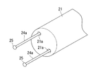
例えば、図7に示されるように、視野の左右方向に離れた位置に形成された各チャネル21a内に、剛性材料からなる丸棒状部材24aが設けられる。丸棒状部材24aは、最先端部に球状の保護部材25が設けられ、心臓A表面を保護しながら接触させられるようになっている。
For example, as shown in FIG. 7, a round bar-
この場合、チャネル21aは、挿入部21の径方向により離れた位置に形成され、各丸棒状部材24aの最先端部の間の幅が、挿入部21の径寸法と略同一またはそれより広いことが好ましい。
このようにすることで、挿入部21の先端部を心臓A表面に固定するとき以外は突起部24を挿入部21内に収納して、挿入部21の操作をより容易にすることができる。
In this case, the
By doing so, the
また、上記実施形態においては、内視鏡2が、突起部24を備えることとしたが、これ代えて、チャネル21a内に出没可能に設けられて出没時に半径方向に広がる処置具26を備えることとしてもよい。
Moreover, in the said embodiment, although the
処置具26は、鉗子様の形状であり、例えば、図8に示されるように、先端部分が、チャネル21a内に収納されるときは長手方向に沿う位置に配され、チャネル21a内から出没させられると、挿入部21の外径寸法より広い寸法まで径方向に開くようになっている。処置具26は、心臓Aの拍動による外力により変形させられない十分に高い剛性を有している。また、処置具26は、最先端部に球状の保護部材25が設けられている。
The
このようにしても、内視鏡2を用いて心臓A表面を処置する場合、処置具26を出没させて心臓A表面に固定することにより、内視鏡2の姿勢が心臓A表面に対して安定させられ、他の処置具による処置を容易に行うことができる。
Even in this case, when treating the surface of the heart A using the
1 シース
2 内視鏡
12 シース本体
12a 内腔
12b 溝
12c 孔
12d 第2の内腔
12e 給排口
13 俸状部材(翼部)
14 ワイヤ(操作部)
15 バネ
16 形状記憶合金ワイヤ(線状部材、翼部)
17 バルーン(翼部)
18 給排手段(操作部)
21 挿入部
21a チャネル
22 湾曲部
23 操作部
24 突起部
24a 丸棒状部材
25 モニタ
26 処置具
A 心臓
B 心嚢膜
C 心嚢内
DESCRIPTION OF SYMBOLS 1
14 Wire (operation part)
15
17 Balloon (wing)
18 Supply / discharge means (operation unit)
21
Claims (15)
該シース本体の先端部に半径方向に出没可能に設けられた翼部と、
前記シース本体の基端側において、前記翼部を出没させる操作部とを備えるシース。 A cylindrical sheath body having flexibility and capable of inserting a medical device therein along the longitudinal direction;
A wing provided in a distal direction of the sheath body so as to be able to appear and disappear in a radial direction;
A sheath provided with an operation part for projecting and retracting the wing part on the proximal end side of the sheath body.
前記操作部が、前記線状部材の他端に接続されて前記シース本体の長手方向に沿って基端側まで延び、前記シース本体の長手方向に移動可能に設けられたワイヤ部材を備える請求項1に記載のシース。 The wing portion has a distal end fixed to a side surface of the sheath body, and is deformable between a substantially linear shape along the side surface of the sheath body and a curved shape curved outward in the radial direction of the sheath body. Provided with a member,
The operation section includes a wire member that is connected to the other end of the linear member, extends to the proximal end side along the longitudinal direction of the sheath body, and is movably provided in the longitudinal direction of the sheath body. The sheath according to 1.
前記操作部が、前記バルーン内に連通し前記シース本体の長手方向に沿って延びる流路と、該流路内へ流体を供給および前記流路内から流体を排出する給排手段とを備える請求項1に記載のシース。 The wing portion is provided on the outer surface of the sheath body, and expands outward in the radial direction of the sheath body while maintaining a substantially constant dimension in a direction perpendicular to the radially outward direction in a cross section of the sheath body. With possible balloons,
The operation unit includes a flow path communicating with the balloon and extending along a longitudinal direction of the sheath body, and supply / discharge means for supplying fluid into the flow path and discharging the fluid from the flow path. Item 2. The sheath according to Item 1.
該挿入部の先端部に、半径方向に出没可能に設けられた翼部と、
前記挿入部より基端側において、前記翼部を出没させる操作部とを備える内視鏡。 An insertion part to be inserted into the body,
A wing provided at the distal end of the insertion portion so as to be able to appear and disappear in a radial direction;
An endoscope including an operation unit that causes the wing portion to appear and retract on a proximal side from the insertion portion.
前記操作部が、前記線状部材の他端に接続されて前記挿入部の長手方向に沿って基端側まで延び、前記挿入部の長手方向に移動可能に設けられたワイヤ部材を備える請求項6に記載の内視鏡。 The wing portion has a distal end fixed to the side surface of the insertion portion, and is deformable between a substantially linear shape along the side surface of the insertion portion and a curved shape curved outward in the radial direction of the insertion portion. Provided with a member,
The operation portion includes a wire member that is connected to the other end of the linear member, extends to the proximal end side along the longitudinal direction of the insertion portion, and is movably provided in the longitudinal direction of the insertion portion. 6. The endoscope according to 6.
前記操作部が、前記バルーン内に連通して前記挿入部の長手方向に沿って基端側まで延びる流路と、該流路内へ流体を供給または前記流路内から流体を排出する給排手段とを備える請求項6に記載の内視鏡。 The wing portion is provided on an outer surface of the insertion portion, and expands radially outward of the insertion portion while maintaining a dimension in a direction orthogonal to the outer side in the radial direction within a cross section of the insertion portion. With possible balloons,
The operation portion communicates with the inside of the balloon and extends to the proximal end side along the longitudinal direction of the insertion portion, and supply / discharge for supplying fluid into the passage or discharging fluid from the passage The endoscope according to claim 6, further comprising: means.
前記翼部が、前記湾曲部より前方に設けられている請求項6に記載の内視鏡。 The insertion portion has a bending portion that can be bent so as to change the direction of the distal end surface;
The endoscope according to claim 6, wherein the wing portion is provided in front of the curved portion.
前記翼部が、前記湾曲部より後方に設けられている請求項6に記載の内視鏡。 The insertion portion has a bending portion that can be bent so as to change the direction of the distal end surface;
The endoscope according to claim 6, wherein the wing portion is provided behind the curved portion.
該挿入部の先端面の方向を変更するように湾曲可能な湾曲部と、
該湾曲部の湾曲可能な方向に交差する方向に離れた少なくとも2箇所を前記先端面より前方に突出させた突起部とを備える内視鏡。 An insertion part to be inserted into the body,
A bending portion that can be bent so as to change the direction of the distal end surface of the insertion portion;
An endoscope comprising: a protruding portion that protrudes forward from the distal end surface at least two places separated in a direction intersecting a bendable direction of the bending portion.
Priority Applications (1)
| Application Number | Priority Date | Filing Date | Title |
|---|---|---|---|
| JP2009057991A JP5649792B2 (en) | 2009-03-11 | 2009-03-11 | Sheath and endoscope |
Applications Claiming Priority (1)
| Application Number | Priority Date | Filing Date | Title |
|---|---|---|---|
| JP2009057991A JP5649792B2 (en) | 2009-03-11 | 2009-03-11 | Sheath and endoscope |
Publications (2)
| Publication Number | Publication Date |
|---|---|
| JP2010207455A true JP2010207455A (en) | 2010-09-24 |
| JP5649792B2 JP5649792B2 (en) | 2015-01-07 |
Family
ID=42968296
Family Applications (1)
| Application Number | Title | Priority Date | Filing Date |
|---|---|---|---|
| JP2009057991A Expired - Fee Related JP5649792B2 (en) | 2009-03-11 | 2009-03-11 | Sheath and endoscope |
Country Status (1)
| Country | Link |
|---|---|
| JP (1) | JP5649792B2 (en) |
Cited By (5)
| Publication number | Priority date | Publication date | Assignee | Title |
|---|---|---|---|---|
| WO2014199648A1 (en) | 2013-06-11 | 2014-12-18 | オリンパス株式会社 | Endoscope |
| JP2017217496A (en) * | 2017-07-27 | 2017-12-14 | オリンパス株式会社 | Endoscope |
| CN108514401A (en) * | 2018-04-04 | 2018-09-11 | 温州市人民医院 | Vagina sutures auxiliary mirror |
| WO2020179014A1 (en) * | 2019-03-06 | 2020-09-10 | オリンパス株式会社 | Pericardial endoscope system |
| CN112020333A (en) * | 2018-04-26 | 2020-12-01 | 奥林巴斯株式会社 | Treatment system and expansion device |
Citations (9)
| Publication number | Priority date | Publication date | Assignee | Title |
|---|---|---|---|---|
| JPS63270037A (en) * | 1987-04-28 | 1988-11-08 | Olympus Optical Co Ltd | Endoscope |
| JPH05103746A (en) * | 1991-10-18 | 1993-04-27 | Olympus Optical Co Ltd | Metabolism information measuring device |
| JPH08286127A (en) * | 1995-04-11 | 1996-11-01 | Asahi Optical Co Ltd | Top end part of endoscope |
| JPH11192201A (en) * | 1997-10-28 | 1999-07-21 | Yuzuru Doi | Length measuring tool for endoscope |
| JP2001258821A (en) * | 2000-03-17 | 2001-09-25 | Asahi Optical Co Ltd | Endoscopic length measuring implement |
| JP2001258822A (en) * | 2000-03-14 | 2001-09-25 | Olympus Optical Co Ltd | Endoscope |
| JP2001275932A (en) * | 2000-03-29 | 2001-10-09 | Asahi Optical Co Ltd | Length-measure for endoscope |
| JP2003220022A (en) * | 2002-01-28 | 2003-08-05 | Olympus Optical Co Ltd | Endoscope |
| WO2007052354A1 (en) * | 2005-11-04 | 2007-05-10 | Olympus Medical Systems Corp. | Endoscope system, endoscope, supporting member and method of using endoscope system |
-
2009
- 2009-03-11 JP JP2009057991A patent/JP5649792B2/en not_active Expired - Fee Related
Patent Citations (9)
| Publication number | Priority date | Publication date | Assignee | Title |
|---|---|---|---|---|
| JPS63270037A (en) * | 1987-04-28 | 1988-11-08 | Olympus Optical Co Ltd | Endoscope |
| JPH05103746A (en) * | 1991-10-18 | 1993-04-27 | Olympus Optical Co Ltd | Metabolism information measuring device |
| JPH08286127A (en) * | 1995-04-11 | 1996-11-01 | Asahi Optical Co Ltd | Top end part of endoscope |
| JPH11192201A (en) * | 1997-10-28 | 1999-07-21 | Yuzuru Doi | Length measuring tool for endoscope |
| JP2001258822A (en) * | 2000-03-14 | 2001-09-25 | Olympus Optical Co Ltd | Endoscope |
| JP2001258821A (en) * | 2000-03-17 | 2001-09-25 | Asahi Optical Co Ltd | Endoscopic length measuring implement |
| JP2001275932A (en) * | 2000-03-29 | 2001-10-09 | Asahi Optical Co Ltd | Length-measure for endoscope |
| JP2003220022A (en) * | 2002-01-28 | 2003-08-05 | Olympus Optical Co Ltd | Endoscope |
| WO2007052354A1 (en) * | 2005-11-04 | 2007-05-10 | Olympus Medical Systems Corp. | Endoscope system, endoscope, supporting member and method of using endoscope system |
Cited By (6)
| Publication number | Priority date | Publication date | Assignee | Title |
|---|---|---|---|---|
| WO2014199648A1 (en) | 2013-06-11 | 2014-12-18 | オリンパス株式会社 | Endoscope |
| JP2017217496A (en) * | 2017-07-27 | 2017-12-14 | オリンパス株式会社 | Endoscope |
| CN108514401A (en) * | 2018-04-04 | 2018-09-11 | 温州市人民医院 | Vagina sutures auxiliary mirror |
| CN108514401B (en) * | 2018-04-04 | 2020-12-15 | 温州市人民医院 | Auxiliary mirror for vaginal suture |
| CN112020333A (en) * | 2018-04-26 | 2020-12-01 | 奥林巴斯株式会社 | Treatment system and expansion device |
| WO2020179014A1 (en) * | 2019-03-06 | 2020-09-10 | オリンパス株式会社 | Pericardial endoscope system |
Also Published As
| Publication number | Publication date |
|---|---|
| JP5649792B2 (en) | 2015-01-07 |
Similar Documents
| Publication | Publication Date | Title |
|---|---|---|
| JP3614943B2 (en) | Endoscopic puncture needle | |
| JP4767252B2 (en) | Lung access device | |
| EP2908742B1 (en) | Retrieval basket apparatus | |
| US9392935B2 (en) | Methods for performing a medical procedure | |
| JP5498056B2 (en) | Medical device introduction device | |
| JP4637903B2 (en) | Endoscope system | |
| US8216185B2 (en) | Cannulated apertured grooved director | |
| JP5649792B2 (en) | Sheath and endoscope | |
| US20050154379A1 (en) | Adjustable laser probe for use in vitreoretinal surgery | |
| JP2008073317A (en) | Endoscopic treatment instrument | |
| KR20190054857A (en) | Bidirectional vertebral endoscopic device for surgery | |
| JP2022552042A (en) | Insertable Robot for Minimally Invasive Surgery | |
| JP2010207251A (en) | Guide wire | |
| JP2009189808A (en) | Surgical instrument | |
| WO2017017753A1 (en) | Tissue recovery tool and tissue recovery system | |
| JP2005058431A (en) | Puncturing needle | |
| JP5019723B2 (en) | Incision forceps | |
| JP2009268753A (en) | Treatment tool for endoscope | |
| JP2006174935A (en) | Puncture needle for endoscope | |
| JP5319043B2 (en) | Endoscopic puncture needle and endoscope apparatus | |
| JP4786807B2 (en) | Endoscopic tube treatment device | |
| CN217907961U (en) | Medical catheter and medical device | |
| JP6267552B2 (en) | Retractor | |
| JP2001120496A (en) | Wound sheath for probe | |
| JPH07148171A (en) | Tube-shaped inserting instrument |
Legal Events
| Date | Code | Title | Description |
|---|---|---|---|
| A621 | Written request for application examination |
Free format text: JAPANESE INTERMEDIATE CODE: A621 Effective date: 20120207 |
|
| A131 | Notification of reasons for refusal |
Free format text: JAPANESE INTERMEDIATE CODE: A131 Effective date: 20131126 |
|
| A521 | Written amendment |
Free format text: JAPANESE INTERMEDIATE CODE: A523 Effective date: 20140127 |
|
| A131 | Notification of reasons for refusal |
Free format text: JAPANESE INTERMEDIATE CODE: A131 Effective date: 20140513 |
|
| A521 | Written amendment |
Free format text: JAPANESE INTERMEDIATE CODE: A523 Effective date: 20140714 |
|
| TRDD | Decision of grant or rejection written | ||
| A01 | Written decision to grant a patent or to grant a registration (utility model) |
Free format text: JAPANESE INTERMEDIATE CODE: A01 Effective date: 20141014 |
|
| A61 | First payment of annual fees (during grant procedure) |
Free format text: JAPANESE INTERMEDIATE CODE: A61 Effective date: 20141112 |
|
| R151 | Written notification of patent or utility model registration |
Ref document number: 5649792 Country of ref document: JP Free format text: JAPANESE INTERMEDIATE CODE: R151 |
|
| S531 | Written request for registration of change of domicile |
Free format text: JAPANESE INTERMEDIATE CODE: R313531 |
|
| R350 | Written notification of registration of transfer |
Free format text: JAPANESE INTERMEDIATE CODE: R350 |
|
| R250 | Receipt of annual fees |
Free format text: JAPANESE INTERMEDIATE CODE: R250 |
|
| LAPS | Cancellation because of no payment of annual fees |