JP2010201480A - Laser building-up welding method - Google Patents
Laser building-up welding method Download PDFInfo
- Publication number
- JP2010201480A JP2010201480A JP2009051550A JP2009051550A JP2010201480A JP 2010201480 A JP2010201480 A JP 2010201480A JP 2009051550 A JP2009051550 A JP 2009051550A JP 2009051550 A JP2009051550 A JP 2009051550A JP 2010201480 A JP2010201480 A JP 2010201480A
- Authority
- JP
- Japan
- Prior art keywords
- laser
- end portion
- output
- valve seat
- irradiation position
- Prior art date
- Legal status (The legal status is an assumption and is not a legal conclusion. Google has not performed a legal analysis and makes no representation as to the accuracy of the status listed.)
- Granted
Links
Images


Abstract
Description
本発明は、シリンダヘッドのバルブシートに金属粉末を供給しつつ、該金属粉末にレーザを照射することにより溶融させて肉盛り層を形成するレーザ肉盛り方法に関する。 The present invention relates to a laser build-up method in which a metal powder is supplied to a valve seat of a cylinder head and melted by irradiating the metal powder with a laser to form a build-up layer.
内燃機関用シリンダヘッドのバルブシートは、バルブに対して繰り返し接触する箇所であることから当該バルブシートに対して耐摩耗性を向上させる加工が施されている。この種の加工には、レーザを照射して金属粉末を溶融させながら該レーザ照射位置を円環状に移動して肉盛りを行うレーザ肉盛加工(レーザクラッドとも呼ばれる)が知られている。
このレーザ肉盛加工では、肉盛りの始端部と終端部が重なり合ってできるオーバーラップ部分に、未溶着部や空孔(ブローホール等)の欠陥が生じ易いことが知られている。そこで、従来、肉盛りの開始時に、金属粉末の供給量を徐々に増加させるとともに該金属粉末の供給量に応じてレーザの出力を増加させることで、厚みを緩やかに増加させた始端部を形成する技術が知られている。この技術によれば、始端部の厚みが他の箇所に比べて薄くなるため、この始端部と終端部のオーバーラップ部分における上記欠陥の発生を抑制することができる(例えば、特許文献1参照)。
It is known that in this laser overlay processing, defects such as unwelded portions and voids (such as blow holes) are likely to occur in an overlap portion formed by overlapping the start and end portions of the overlay. Therefore, conventionally, at the start of the build-up, the supply amount of the metal powder is gradually increased and the output of the laser is increased in accordance with the supply amount of the metal powder, thereby forming a starting end portion having a moderately increased thickness. The technology to do is known. According to this technique, since the thickness of the starting end portion is thinner than other portions, the occurrence of the defect in the overlapping portion between the starting end portion and the terminating end portion can be suppressed (for example, see Patent Document 1). .
しかしながら、従来の技術においても、上記欠陥を依然としてなくすことができず、バルブシートの歩留まりを向上させるためには、更なる改良が求められている。
本発明は、上述した事情に鑑みてなされたものであり、シリンダヘッドのバルブシートに肉盛りするに当たり、肉盛り層に生じる欠陥を更に抑制可能なレーザ肉盛方法を提供することを目的とする。
However, even in the prior art, the above-described defects cannot still be eliminated, and further improvement is required in order to improve the yield of the valve seat.
The present invention has been made in view of the above-described circumstances, and an object of the present invention is to provide a laser cladding method capable of further suppressing defects generated in the overlay layer when overlaying the valve seat of the cylinder head. .
上記目的を達成するために、本発明は、シリンダヘッドのバルブシートに金属粉末を供給しながらレーザを照射することでレーザ照射位置に肉盛り層を形成しつつ、該レーザ照射位置を前記バルブシートに沿って円環状に移動させて肉盛りするレーザ肉盛方法において、前記肉盛りの開始時に、前記金属粉末の供給量を徐々に増加させながら該金属粉末の供給量に応じてレーザ出力を増加させて肉盛りの始端部を形成し、前記金属粉末の供給量及び前記レーザの出力を一定に維持して肉盛りの通常部を形成し、前記始端部の手前から前記金属粉末の供給量を一定のままで前記レーザの出力を所定量まで増加させて肉盛りの終端部を形成し前記始端部に重ねることを特徴とする。 In order to achieve the above-described object, the present invention provides a method for forming a built-up layer at a laser irradiation position by irradiating a laser while supplying a metal powder to a valve seat of a cylinder head, and setting the laser irradiation position to the valve seat. In the laser overlaying method in which the metal powder is moved in an annular shape along the line, the laser output is increased according to the supply amount of the metal powder while gradually increasing the supply amount of the metal powder at the start of the buildup. To form a starting end portion of the buildup, to maintain the supply amount of the metal powder and the output of the laser constant, to form a normal portion of the buildup, and to supply the supply amount of the metal powder from before the start end portion The laser output is increased to a predetermined amount while maintaining a constant value, and a terminal end portion of the build-up is formed and overlapped with the start end portion.
円環状にレーザ照射位置を移動させて肉盛りを行う場合、レーザ照射位置が始端部の手前まで来ると、始端部及び通常部形成の間にレーザ照射位置の上流側に溜まった残留粉が始端部に押されてレーザ照射位置に入り込み、このレーザ照射位置での粉量が増加する。
本発明によれば、始端部の手前からレーザの出力を増加させて終端部の形成を開始するため、レーザ照射位置での粉量の増加に合せてレーザ出力も増加されることから、終端部での欠陥の発生が抑えられる。
When overlaying by moving the laser irradiation position in an annular shape, if the laser irradiation position comes before the start end, residual powder accumulated upstream of the laser irradiation position during the start end and normal part formation will start. It is pushed by the part and enters the laser irradiation position, and the amount of powder at this laser irradiation position increases.
According to the present invention, since the output of the laser is increased from the front of the start end portion to start the formation of the end portion, the laser output is also increased in accordance with the increase in the amount of powder at the laser irradiation position. The occurrence of defects in the is suppressed.
本発明において、前記終端部の形成時には、前記始端部に重なる前までに、前記始端部に形成された傾斜に応じて、前記レーザの出力を前記所定量まで徐々に増加させても良い。
すなわち、始端部に押されてレーザ照射位置に入り込む残留粉の量は、始端部の傾斜に応じて徐々に増加するため、この増加に合せてレーザの出力を増加させることで、欠陥の発生を更に抑制することができる。
In the present invention, when the terminal portion is formed, the output of the laser may be gradually increased to the predetermined amount in accordance with the inclination formed at the starting end portion before being overlapped with the starting end portion.
That is, the amount of residual powder that is pushed into the laser irradiation position by being pushed by the start end portion gradually increases with the inclination of the start end portion, so that the generation of defects is increased by increasing the laser output in accordance with this increase. Further suppression can be achieved.
また本発明において、前記バルブシートのシート面に沿って溝部を形成し、該溝部に前記肉盛り層を形成しても良い。
溝部に前記肉盛り層を形成することで、バルブシートの更なる耐摩耗性の向上が図られる。また、肉盛り時に溝部に金属粉末が溜まり易くなるものの、上記のように、残留粉の量に合せてレーザ出力が増加されることで欠陥の発生が抑制される。これにより、耐摩耗性の向上とともに欠陥の更なる抑制効果が得られる。
Moreover, in this invention, a groove part may be formed along the seat surface of the said valve seat, and the said build-up layer may be formed in this groove part.
By forming the build-up layer in the groove, the wear resistance of the valve seat can be further improved. Moreover, although metal powder tends to accumulate in the groove portion when building up, as described above, the generation of defects is suppressed by increasing the laser output in accordance with the amount of residual powder. Thereby, the further suppression effect of a defect is acquired with the improvement of abrasion resistance.
また本発明において、前記バルブシートの中央を中心に前記レーザ照射位置を円環状に移動させる場合、前記始端部から約270度〜約315度移動したタイミングで前記終端部の形成を開始しても良い。
バルブシートの肉盛り加工においては、始端部から約270〜315度移動したタイミングで、始端部に残留粉が押されてレーザ照射位置に入り込み始めるため、この時点から上記のようにレーザ出力を増加させて終端部の形成を開始することで、欠陥の発生を抑えた肉盛りを良好に行うことができる。
Further, in the present invention, when the laser irradiation position is moved in an annular shape around the center of the valve seat, even if the formation of the end portion is started at a timing moved from about 270 degrees to about 315 degrees from the start end portion. good.
In valve seating processing, residual powder starts to enter the laser irradiation position at the timing of approximately 270 to 315 degrees of movement from the starting end, and the laser output increases from this point as described above. Then, by starting the formation of the terminal portion, it is possible to satisfactorily build up the occurrence of defects.
本発明によれば、始端部の手前からレーザの出力を増加させて終端部の形成を開始することで、レーザ照射位置の上流側に溜まっていた残留粉がレーザ照射位置に入り込み粉量が増加した場合でも終端部での欠陥の発生が抑えられる。
また、終端部の形成時には、始端部に重なる前までに、始端部に形成された傾斜に応じて、レーザの出力を前記所定量まで徐々に増加させることで、始端部の傾斜に応じて徐々に増加するレーザ照射位置での粉末量に合せてレーザの出力が増加され、欠陥の発生を更に抑制することができる。
また、バルブシートのシート面に沿って溝部を形成し、該溝部に前記肉盛り層を形成することで、バルブシートの更なる耐摩耗性の向上が図られる。さらに、残留粉の量に合せてレーザ出力が増加されるため欠陥の発生が抑制される。
また、バルブシートの中央を中心に前記レーザ照射位置を円環状に移動させる場合、始端部から約270度〜約315度移動したタイミングで終端部の形成を開始することで、欠陥の発生を良好に抑えたバルブシートの肉盛りを行うことができる。
According to the present invention, by increasing the laser output from the front of the start end and starting the formation of the end portion, the residual powder accumulated on the upstream side of the laser irradiation position enters the laser irradiation position and the amount of powder increases. Even in this case, the occurrence of defects at the terminal portion can be suppressed.
In addition, when the terminal portion is formed, the output of the laser is gradually increased to the predetermined amount according to the inclination formed at the starting end portion before being overlapped with the starting end portion, so that it gradually increases according to the inclination of the starting end portion. The output of the laser is increased in accordance with the amount of powder at the laser irradiation position that increases, and the generation of defects can be further suppressed.
Further, by forming a groove portion along the seat surface of the valve seat and forming the build-up layer in the groove portion, the wear resistance of the valve seat can be further improved. Furthermore, since the laser output is increased in accordance with the amount of residual powder, the occurrence of defects is suppressed.
In addition, when the laser irradiation position is moved in an annular shape around the center of the valve seat, the formation of the end portion is started at a timing moved from about 270 degrees to about 315 degrees from the start end portion, so that the occurrence of defects is good. It is possible to build up the valve seat that is kept to a minimum.
以下、図面を参照して本発明の実施形態について説明する。
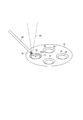
図1は、本実施形態に係るバルブシート16のレーザ肉盛方法で用いられるレーザクラッド装置10を示す図であり、図2は、シリンダヘッド12を示す図である。
レーザクラッド装置10は、ワークであるシリンダヘッド12における給排気用バルブ孔14(図2参照)の周囲のバルブシート16に対して、銅合金粉末(金属粉末)18を供給しながら半導体レーザのレーザ光20を照射して銅合金粉末18を溶融及び固化させてレーザ照射位置Pに肉盛り層を形成し、このレーザ照射位置P(図2参照)を環状に移動しながら肉盛りをする装置である。
Hereinafter, embodiments of the present invention will be described with reference to the drawings.
FIG. 1 is a view showing a laser
The
シリンダヘッド12は4気筒型のエンジン用であり、図2に示すように、各気筒当たり4つのバルブシート16が設けられている。このバルブシート16のシート面16Aには、肉盛り用のU字溝部17が周囲に沿って設けられている。シリンダヘッド12はアルミ合金製であり軽量化が図られている。また、シリンダヘッド12のバルブシート16は、バルブに対して繰り返し接触し、シート面16Aのヘルツ面圧は高負荷で、なおかつ、この高負荷が連続的に付与されることから、上記のように該シート面16Aに肉盛りすることで耐摩耗性及び耐熱性の向上が図られている。銅合金粉末18は、銅及びニッケルをベースとする合金の粉末であり、アトマイズ粉末となっている。
The
レーザクラッド装置10は、シリンダヘッド12を水平二軸方向に移動して位置決めを行うとともに所定のバルブシート16を中心として回転させるテーブル22と、該テーブル22の制御を行うテーブルコントローラ24と、バルブシート16に対して銅合金粉末18を供給するフィード機構26と、このフィード機構26を制御するフィードコントローラ28とを有する。フィード機構26の収納部26aには銅合金粉末18が投入されており、フィードコントローラ28の作用下にノズル29を介して銅合金粉末18をバルブシート16の周囲の一部に供給可能である。この銅合金粉末18の供給量Sは、フィードコントローラ28により調整可能である。
The
また、レーザクラッド装置10は、バルブシート16に対して半導体レーザのレーザ光20を照射するレーザ発振機構部30と、該レーザ発振機構部30を制御するレーザコントローラ32と、バルブシート16の拡大撮影を行うカメラ34と、該カメラ34により撮像された画像を表示するモニタ36とを有する。カメラ34は、例えば、CCD式又はMOS式の撮像部を有するカメラである。さらに、レーザクラッド装置10は、テーブルコントローラ24、フィードコントローラ28、レーザコントローラ32及びカメラ34を統合的に制御するメインコントローラ40を有する。
The
レーザ発振機構部30は、例えば、モジュール式でGaaAlbAs型(a,bは固相比)のレーザ発振部を有し、半導体のPN接合部からレーザ光20を発生する装置であり、このレーザ光20の波長は、半導体の成分により800〜950[nm]の範囲の所定値となるように設定されている。また、レーザ発振機構部30は、レーザコントローラ32の作用下にレーザ光20の出力Wを調整可能であって、具体的には、PN接合部に印加する制御電圧を変更することによりレーザ光20の出力Wを調整する。レーザ光20の出力Wは、印加電圧を変更することにより瞬時に変化し、応答遅れや出力Wの変化時のオーバシュート等がなく、印加電圧に対して極めて高い応答性を有する。従って、レーザ光20の出力Wは、徐々に変化させることが可能であるとともに、段階的に変化させることも可能である。
また、このレーザ光20の800〜950[nm]の波長範囲は、銅合金粉末18にエネルギーが吸収され易く、銅合金粉末18を効率良く溶融させるため、半導体レーザは、1.2〜2.0[kW]程度の低出力で足り、シリンダヘッド12に対する熱影響を低減できる。しかも銅合金粉末18による溶融池は大きくなり肉盛り層の厚肉化が可能であり、例えば、5[mm]の厚さを形成することができる。
The laser
Further, in the wavelength range of 800 to 950 [nm] of the
レーザ発振機構部30は、バルブシート16に対してシールドガスとして不活性ガス(アルゴンガス等)を吹きつけることができる。レーザ発振機構部30はテーブル22に対する高さ調整が可能である。
The laser
次に、このように構成されるレーザクラッド装置10を用いてバルブシート16に肉盛りを行う方法について説明する。
先ず、所定の手順によりテーブル22上にシリンダヘッド12を取り付け、テーブルコントローラ24の作用下に所定のバルブシート16が回転中心位置に配置されるように水平位置決めを行う。
次いで、図2に示すように、バルブシート16の周囲の一部に対してフィード機構26のノズル29から銅合金粉末18を供給するとともにレーザ発振機構部30からレーザ光20を照射し、テーブル22を回転させる。テーブル22、フィード機構26及びレーザ発振機構部30は、テーブルコントローラ24、フィードコントローラ28及びレーザコントローラ32により制御され、それぞれメインコントローラ40の作用下に同期し、同時に動作を開始する。また、シールドガスの噴出も同時に開始する。
Next, a method for overlaying the
First, the
Next, as shown in FIG. 2, the
このとき、テーブル22の回転速度がバルブシート16の大きさに応じた一定の速度に維持されつつ、銅合金粉末18の供給量S及びレーザ光20の出力Wは、図3に示すように、テーブル22の回転に伴うバルブシート16の回転角度[deg]に基づいて可変制御される。
At this time, while the rotation speed of the table 22 is maintained at a constant speed according to the size of the
すなわち、肉盛り開始時には、銅合金粉末18の供給量Sを徐々に最適値Saまで増加させながら、この銅合金粉末18の供給量Sに応じてレーザ光20の出力Wを徐々に最適値Waまで増加させて肉盛りの始端部50の形成が行われる((I)始端部形成工程))。このように、銅合金粉末18の供給量Sを徐々に増加させながら肉盛りが行われることで、図4に示すように、肉盛り層の厚みが緩やかに増加した始端部50が形成されるため、後に説明する終端部52がオーバーラップした際に、このオーバーラップ部54での欠陥の発生が抑制される。
That is, at the start of the build-up, the output W of the
ところで、一般に、アルミニウムと銅との拡散層の厚みが50[μm]以下となると未溶着によるブローホールの発生が多くなり、400[μm]以上となると、アルミニウムと銅との合金化割れが発生しやすくなることが知られている。本レーザ肉盛方法では、供給量Sに合せて出力Wを調整することから、母材であるシリンダヘッド12の溶融量が適正量となって、拡散層の厚さを50〜400[μm]とされる。これにより、合金化割れ及び未溶着を防止し、結果として欠陥の発生を防止することができる。
なお、レーザ光20の出力Wの制御方法は、例えば、所定時間毎の供給量Sをタイマを用いて測定し、該供給量Sに合せて出力Wを制御するとよい。
By the way, generally, when the thickness of the diffusion layer of aluminum and copper is 50 [μm] or less, blowholes are generated due to non-welding, and when it is 400 [μm] or more, alloying cracks between aluminum and copper are generated. It is known to be easy to do. In this laser cladding method, since the output W is adjusted in accordance with the supply amount S, the amount of melting of the
As a method for controlling the output W of the
次いで、銅合金粉末18の供給量S及びレーザ光20の出力Wを、それぞれ最適値Sa、Waに維持して肉盛りの通常部51の形成が行われる((II)通常部形成工程)。これにより、図4に示すように、略一定の厚みの肉盛り層を有する通常部51が形成される。上記最適値Sa、Wbには、通常の厚みの肉盛り層を形成するときにシリンダヘッド12の溶融量を適正量とする値が設定されており、これにより、当該通常部51での欠陥の発生も抑制される。
Next, the
その後、始端部50に合流し重なり合う終端部52の形成が行われる((III)終端部形成工程)。この終端部形成工程は、環状に移動したレーザ照射位置Pが始端部50に至る前(回転角度360[deg]より前)のタイミングで開始される。また、終端部形成工程では、通常部形成工程と異なり、銅合金粉末18の供給量Sを最適値Saに一定にしたままで、レーザ光20の出力Wを所定量Wb(>Wa)まで増加させて終端部52の形成が行われる。
Thereafter, the
さらに詳述すると、発明者らは、レーザ照射位置Pを高速度カメラで撮影し観察した結果、レーザクラッドにおいては、図5に示すように、ノズル29から噴射された銅合金粉末18が、レーザ照射位置P(溶融池60)に対してワーク回転方向上流側のゾーンK1に残留し、また、始端部50の面上のゾーンK2には赤熱した銅合金粉末18が飛散するとの知見を得た。
More specifically, as a result of observing the laser irradiation position P with a high-speed camera, the inventors have observed that the
すなわち、始端部50及び通常部51の形成の間、ゾーンK1に残留粉が溜まり込むこととなるが、レーザ照射位置Pが環状に移動し、当初の始端部50の手前まで来ると、図4の(III)終端部形成工程に示すように、ゾーンK1の残留粉が始端部50に押されてレーザ照射位置Pに入り込む。
これにより、レーザ照射位置Pでは、銅合金粉末18の供給量Saに加えて残留粉の分だけ増加するため、銅合金粉末18の粉量とレーザ光20の出力Wのバランスが崩れる。このため、何ら対策を施さなければ、図6に示すように、レーザ照射位置Pが始端部50に至る手前(回転角度が約−90[deg])の位置から始端部50にかけた肉盛り層で欠陥が集中的に発生する。
特に、本レーザ肉盛り方法では、バルブシート16の肉盛り用のU字溝部17に沿ってレーザ肉盛りを行っているため、該U字溝部17に残留粉が溜まり易くなる。
That is, while the starting
As a result, at the laser irradiation position P, in addition to the supply amount Sa of the
In particular, in this laser embedding method, since the laser embedding is performed along the
そこで、本レーザ肉盛り方法では、ゾーンK1の残留粉が始端部50に押されてレーザ照射位置Pに入り込み始めるタイミングから終端部形成工程を開始し、この終端部形成工程において、レーザ光20の出力Wを所定量Wbまで次第に増加させる。この結果、レーザ照射位置Pでの銅合金粉末18の粉量増加に合せてレーザ光20の出力Wが増加するため、銅合金粉末18の粉量とレーザ光20の出力Wのバランスが維持され肉盛り層の欠陥の発生が抑制されることとなる。
Therefore, in this laser cladding method, the terminal portion forming process is started from the timing at which the residual powder in the zone K1 starts to enter the laser irradiation position P by being pushed by the starting
この終端部形成工程においては、その開始時からレーザ光20の出力Wを、始端部50に形成した傾斜に応じた増加率αで所定量Wbまで増加させている。
詳述すると、始端部50の傾斜面がゾーンK1の残留粉をレーザ照射位置Pに押し込むことから、押し込みの量の時間的変化は傾斜面の緩急に応じて変化する。すなわち、始端部50の傾斜面が緩やかなほど、レーザ照射位置PへのゾーンK1の残留粉の押し込み量も緩やかに増加する。そして、レーザ照射位置Pへの残留粉の押し込み量の時間的変化に合せてレーザ光20の出力Wが徐々に高められることで、欠陥の発生が更に抑制される。
In this termination portion forming step, the output W of the
More specifically, since the inclined surface of the
本レーザ肉盛り方法では、始端部50の傾斜面の角度θ(図5参照)が約30〜40度となるように、始端部形成工程での銅合金粉末18の供給量S等が設定されている。この角度の傾斜面が始端部50に形成されることで、始端部50が残留粉をレーザ照射位置Pに押し込む際に、当該始端部50の傾斜面上に回り込む残留粉も増える。これにより、レーザ照射位置Pでの銅合金粉末18の粉量の時間的変化を、傾斜面の角度に対してより緩やかにすることができ、一層良好に終端部52での欠陥の発生を抑制できる。また、傾斜面の角度をある程度大きくできるため、始端部形成工程において、銅合金粉末18の供給量Sを微小変化させる必要がなく、始端部50の形成が容易となる。
In this laser build-up method, the supply amount S of the
ここで、始端部50の傾斜面上のゾーンK2(図5参照)には、上記の残留粉の回り込みに加え、レーザ照射位置Pの観察の結果、赤熱した粉末が飛散するとの知見が得られている。終端部形成工程では、レーザ照射位置Pが始端部50に到達した後も、ノズル29から銅合金粉末18の供給を継続して、この始端部50の上にオーバーラップ部54を形成しており、始端部50の傾斜面上のゾーンK2では粉量が増加した状態となる。このため、何ら対策を施さなければ、図6に示すように、オーバーラップ部54においても比較的多くの欠陥が発生する。
そこで本レーザ肉盛り方法では、レーザ照射位置Pが始端部50に重なった後も、レーザ光20の出力Wを所定量Wbまで高めた状態で、オーバーラップ部54の形成を行う((III−A)オーバーラップ部形成工程)。この結果、上記ゾーンK2で粉末の粉量が増加しても、レーザ光20の出力Wが高められているため、欠陥の発生が良好に抑制される。
Here, in the zone K2 (refer to FIG. 5) on the inclined surface of the starting
Therefore, in this laser overlaying method, the
上記出力Wの所定値Wbは、ゾーンK1の残留粉の堆積量、より詳細には、レーザ照射位置Pでの粉量の最大値(供給量Sa+残留粉)に応じて決定される。詳細には、この最大値に占める残留粉の割合は、バルブシート16のレーザ肉盛りにおいては略一定であるとの知見が得られており、所定値Wbを、出力Wの最適値Waに対して約20〜30%の範囲で増加させることで欠陥が良好に抑制される。すなわち、所定値Wbを所定値Wbよりも約30%を超えて設定すると肉盛り層にクラックが発生し、所定値Wbよりも約20%を下回って設定すると肉盛り層に欠陥が発生することとなる。
The predetermined value Wb of the output W is determined in accordance with the accumulated amount of residual powder in the zone K1, more specifically, the maximum value of powder amount at the laser irradiation position P (supply amount Sa + residual powder). Specifically, it has been found that the ratio of the residual powder to the maximum value is substantially constant in the laser build-up of the
さらに、バルブシート16のレーザ肉盛りにおいては、バルブシート16の回転に伴い始端部50の形成開始からレーザ照射位置Pが約270〜315度移動したタイミングでゾーンK1の残留粉が始端部50に押され始めるとの知見が得られている。したがって、かかるタイミングで終端部形成工程を開始することで、レーザ照射位置Pでの粉量が増え始める適正なタイミングでレーザ光20の出力Wを増加させることができ、欠陥を抑えた終端部52を形成することができる。
Further, in the laser build-up of the
図3に示すように、オーバーラップ部形成工程では、始端部50における肉盛り層が所定の一定厚さとなる位置まで肉盛りが続けられる。そして、その後に銅合金粉末18の供給とレーザ光20とを停止させ、バルブシート16に対する肉盛りを終了する。なお、終了時には、供給量Sと出力Wとを徐々に減少させ、終端部52のオーバーラップ部54における肉盛り層が徐々に薄くなるようにして肉盛りを終了させてもよい。
さらにこの後、肉盛りの処理が行われていない他のバルブシート16に対しても同様の肉盛り処理を順次行う。
As shown in FIG. 3, in the overlap portion forming step, the build-up is continued until the build-up layer at the
Thereafter, the same build-up process is sequentially performed on the
以上説明したように、本実施形態に係るバルブシート16のレーザ肉盛方法によれば、始端部50の手前から終端部形成工程を開始し、この終端部形成工程においては、レーザ光20の出力Wを増加させて終端部52を形成することとした。これにより、レーザ照射位置Pの上流側のゾーンK1に溜まっていた残留粉が始端部50に押されてレーザ照射位置Pに入り込み、このレーザ照射位置Pでの粉量が供給量Sの最適値Saより増加した場合でも、この増加に合せてレーザ光20の出力Wも増加されることから、終端部52での欠陥の発生が抑えられる。また、始端部50が残留粉を押し込んだ際に、残留粉が始端部50の面上に回り込むことで、始端部50の傾斜面上での粉量が増加するものの、レーザ光20の出力Wを増加させたまま始端部50とのオーバーラップ部54を形成するため、オーバーラップ部54での欠陥の発生も良好に抑制できる。
As described above, according to the laser cladding method for the
また、終端部形成工程では、レーザ照射位置Pが始端部50に重なる前までに、始端部50に形成された傾斜に応じた増加率αでレーザ光20の出力Wを所定量Wbまで徐々に増加させている。
これにより、始端部50の傾斜に応じて、レーザ照射位置Pで徐々に増加する残留粉の粉量に合せてレーザ光20の出力Wが増加することとなり、欠陥の発生を更に抑制して終端部52を形成することができる。
In the terminal portion forming step, the output W of the
As a result, the output W of the
また、バルブシート16のシート面16Aに沿ってU字溝部17を形成し、U字溝部17に肉盛り層を形成している。このようにU字溝部17に肉盛り層を形成することで、バルブシート16の更なる耐摩耗性の向上が図られる。また、肉盛り時にU字溝部17に銅合金粉末18が溜まり易くなるものの、上記のように、終端部形成工程では、残留粉の粉量に合せてレーザ光20の出力Wが増加されるため、欠陥の発生を良好に抑制することができる。これにより、耐摩耗性の向上とともに欠陥の良好な抑制効果が得られる。
Further, a
また、レーザ照射位置Pが始端部50から円環状に約270度〜約315度移動したタイミングで終端部形成工程を開始している。これによれば、バルブシート16のレーザ肉盛りにおいて、レーザ照射位置Pでの粉量が増え始める適正なタイミングでレーザ光20の出力Wを増加させることができ、欠陥を抑えた終端部52を形成することができる。
In addition, the end portion forming process is started at a timing when the laser irradiation position P is moved from the
なお、上述した実施の形態は、あくまでも本発明の一態様を示すものであり、本発明の主旨を逸脱しない範囲で任意に変形および応用が可能である。
例えば、始端部形成工程及び終端部形成工程では、レーザ光20の出力Wを、図3に示したように、回転角度に比例的に増加させるものとして説明したが、ステップ状に段階的に増加させるようにしてもよい。出力Wを段階的に変更することにより、レーザコントローラ32は印加電圧のリアルタイム的な制御が不要となり、簡便な手順で肉盛り処理を行うことができる。
The above-described embodiment is merely an aspect of the present invention, and can be arbitrarily modified and applied without departing from the gist of the present invention.
For example, in the start end portion forming step and the end portion forming step, the output W of the
10 レーザクラッド装置
12 シリンダヘッド
14 給排気用バルブ孔
16 バルブシート
16A シート面
17 U字溝部
18 銅合金粉末(金属粉末)
20 レーザ光
29 ノズル
50 始端部
51 通常部
52 終端部
54 オーバーラップ部
60 溶融池
P レーザ照射位置
Wb 所定値
K1、K2 ゾーン
DESCRIPTION OF
20
Claims (4)
前記肉盛りの開始時に、前記金属粉末の供給量を徐々に増加させながら該金属粉末の供給量に応じてレーザ出力を増加させて肉盛りの始端部を形成し、
前記金属粉末の供給量及び前記レーザの出力を一定に維持して肉盛りの通常部を形成し、
前記始端部の手前から前記金属粉末の供給量を一定のままで前記レーザの出力を所定量まで増加させて肉盛りの終端部を形成し前記始端部に重ねる
ことを特徴とするレーザ肉盛方法。 By irradiating a laser while supplying metal powder to the valve seat of the cylinder head, a build-up layer is formed at the laser irradiation position, and the laser irradiation position is moved annularly along the valve seat to build up In the laser cladding method,
At the start of the build-up, gradually increasing the supply amount of the metal powder while increasing the laser output according to the supply amount of the metal powder to form the start end of the build-up,
The supply amount of the metal powder and the output of the laser are kept constant to form a normal part of the overlay,
A laser cladding method comprising: forming a terminal end portion of a built-up by overlapping a supply end of the metal powder from a position before the start end portion to increase a laser output to a predetermined amount and overlapping the start end portion .
Priority Applications (1)
| Application Number | Priority Date | Filing Date | Title |
|---|---|---|---|
| JP2009051550A JP5228223B2 (en) | 2009-03-05 | 2009-03-05 | Laser overlaying method |
Applications Claiming Priority (1)
| Application Number | Priority Date | Filing Date | Title |
|---|---|---|---|
| JP2009051550A JP5228223B2 (en) | 2009-03-05 | 2009-03-05 | Laser overlaying method |
Publications (2)
| Publication Number | Publication Date |
|---|---|
| JP2010201480A true JP2010201480A (en) | 2010-09-16 |
| JP5228223B2 JP5228223B2 (en) | 2013-07-03 |
Family
ID=42963501
Family Applications (1)
| Application Number | Title | Priority Date | Filing Date |
|---|---|---|---|
| JP2009051550A Expired - Fee Related JP5228223B2 (en) | 2009-03-05 | 2009-03-05 | Laser overlaying method |
Country Status (1)
| Country | Link |
|---|---|
| JP (1) | JP5228223B2 (en) |
Cited By (4)
| Publication number | Priority date | Publication date | Assignee | Title |
|---|---|---|---|---|
| DE102012010473A1 (en) | 2012-05-26 | 2012-11-22 | Daimler Ag | Coating substrate using laser, comprises melting substrate for producing coating in region of processing point using laser beam produced by laser along track to be coated and varying powder mass flow |
| DE102012010476A1 (en) | 2012-05-26 | 2012-11-22 | Daimler Ag | Method for coating of substrate used in valve seat of cylinder head, involves varying powder mass flow and feed rate related to movement of substrate along track during start and stop of coating process |
| DE102012014111A1 (en) | 2012-07-17 | 2014-01-23 | Daimler Ag | Method for coating substrate using laser, involves indirectly detecting mass flow rate of coating powder, such that power of laser is adjusted depending on detected size |
| EP3117952A1 (en) | 2015-07-16 | 2017-01-18 | Toyota Jidosha Kabushiki Kaisha | Laser build-up method |
Citations (4)
| Publication number | Priority date | Publication date | Assignee | Title |
|---|---|---|---|---|
| JP2000158161A (en) * | 1998-11-24 | 2000-06-13 | Nissan Motor Co Ltd | Padding method by laser beam |
| JP2002086284A (en) * | 2000-09-11 | 2002-03-26 | Nissan Motor Co Ltd | Overlaying method with laser beam |
| JP2002103068A (en) * | 2000-09-22 | 2002-04-09 | Nissan Motor Co Ltd | Method and apparatus for judging quality of laser beam cladding |
| JP2005299598A (en) * | 2004-04-15 | 2005-10-27 | Honda Motor Co Ltd | Laser building-up method for valve seat |
-
2009
- 2009-03-05 JP JP2009051550A patent/JP5228223B2/en not_active Expired - Fee Related
Patent Citations (4)
| Publication number | Priority date | Publication date | Assignee | Title |
|---|---|---|---|---|
| JP2000158161A (en) * | 1998-11-24 | 2000-06-13 | Nissan Motor Co Ltd | Padding method by laser beam |
| JP2002086284A (en) * | 2000-09-11 | 2002-03-26 | Nissan Motor Co Ltd | Overlaying method with laser beam |
| JP2002103068A (en) * | 2000-09-22 | 2002-04-09 | Nissan Motor Co Ltd | Method and apparatus for judging quality of laser beam cladding |
| JP2005299598A (en) * | 2004-04-15 | 2005-10-27 | Honda Motor Co Ltd | Laser building-up method for valve seat |
Cited By (7)
| Publication number | Priority date | Publication date | Assignee | Title |
|---|---|---|---|---|
| DE102012010473A1 (en) | 2012-05-26 | 2012-11-22 | Daimler Ag | Coating substrate using laser, comprises melting substrate for producing coating in region of processing point using laser beam produced by laser along track to be coated and varying powder mass flow |
| DE102012010476A1 (en) | 2012-05-26 | 2012-11-22 | Daimler Ag | Method for coating of substrate used in valve seat of cylinder head, involves varying powder mass flow and feed rate related to movement of substrate along track during start and stop of coating process |
| DE102012014111A1 (en) | 2012-07-17 | 2014-01-23 | Daimler Ag | Method for coating substrate using laser, involves indirectly detecting mass flow rate of coating powder, such that power of laser is adjusted depending on detected size |
| EP3117952A1 (en) | 2015-07-16 | 2017-01-18 | Toyota Jidosha Kabushiki Kaisha | Laser build-up method |
| US20170014951A1 (en) * | 2015-07-16 | 2017-01-19 | Toyota Jidosha Kabushiki Kaisha | Laser build-up method |
| JP2017024015A (en) * | 2015-07-16 | 2017-02-02 | トヨタ自動車株式会社 | Laser build-up method |
| US10449634B2 (en) | 2015-07-16 | 2019-10-22 | Toyota Jidosha Kabushiki Kaisha | Laser build-up method |
Also Published As
| Publication number | Publication date |
|---|---|
| JP5228223B2 (en) | 2013-07-03 |
Similar Documents
| Publication | Publication Date | Title |
|---|---|---|
| JP3209369U (en) | A system for starting and using a combination of filler wire feed and high-intensity energy source for root-pass welding of inner diameter of clad pipe | |
| KR102093528B1 (en) | Method of and system for starting and using in combination a filler wire feed and arc generating source for welding | |
| JP5228223B2 (en) | Laser overlaying method | |
| KR20160140849A (en) | System and method of welding with use of ac welding waveform and enhanced consumable to improve welding of galvanized workpiece | |
| US20050284853A1 (en) | Arc starting method in arc welding attended with laser irradiation, welding device for performing the method, and controller | |
| JP4359529B2 (en) | Laser seating method for valve seat | |
| JP5228224B2 (en) | Laser overlaying method | |
| JP3591147B2 (en) | Method of overlaying with laser beam | |
| Victor | Hybrid laser arc welding | |
| JP5532629B2 (en) | Laser cladding valve sheet forming method and laser cladding valve sheet forming apparatus | |
| JP4848921B2 (en) | Composite welding method and composite welding equipment | |
| JP2012206144A (en) | Laser narrow groove multi-pass welding method and apparatus | |
| JP2010125512A (en) | Laser arc combination welding method | |
| KR20160036583A (en) | Method for creating a textured bond coat surface | |
| FR2684033A1 (en) | LASER COATING PROCESS FOR CYLINDRICAL PARTS. | |
| JP2016509541A (en) | Laser micro-cladding using powdered flux and powdered metal | |
| RU2708715C1 (en) | Method for hybrid laser-arc surfacing of metal articles | |
| JP5959849B2 (en) | Laser overlay welding method | |
| JP4344654B2 (en) | Laser overlaying method | |
| JP3724354B2 (en) | Method of overlaying with laser beam | |
| JP7284014B2 (en) | Laser-arc hybrid welding equipment | |
| JP5294589B2 (en) | Valve seat forming method and cylinder head | |
| JP2011062728A (en) | Laser beam welding method and laser beam welding apparatus | |
| JP2010209701A (en) | Laser cladding method for forming valve seat and laser cladding device for forming valve seat | |
| JP3173705B2 (en) | Overlay method |
Legal Events
| Date | Code | Title | Description |
|---|---|---|---|
| A621 | Written request for application examination |
Free format text: JAPANESE INTERMEDIATE CODE: A621 Effective date: 20111124 |
|
| A521 | Written amendment |
Free format text: JAPANESE INTERMEDIATE CODE: A523 Effective date: 20120517 |
|
| A977 | Report on retrieval |
Free format text: JAPANESE INTERMEDIATE CODE: A971007 Effective date: 20130214 |
|
| TRDD | Decision of grant or rejection written | ||
| A01 | Written decision to grant a patent or to grant a registration (utility model) |
Free format text: JAPANESE INTERMEDIATE CODE: A01 Effective date: 20130219 |
|
| A61 | First payment of annual fees (during grant procedure) |
Free format text: JAPANESE INTERMEDIATE CODE: A61 Effective date: 20130227 |
|
| FPAY | Renewal fee payment (event date is renewal date of database) |
Free format text: PAYMENT UNTIL: 20160329 Year of fee payment: 3 |
|
| R150 | Certificate of patent or registration of utility model |
Free format text: JAPANESE INTERMEDIATE CODE: R150 |
|
| LAPS | Cancellation because of no payment of annual fees |