JP2010200543A - Motor - Google Patents
Motor Download PDFInfo
- Publication number
- JP2010200543A JP2010200543A JP2009044553A JP2009044553A JP2010200543A JP 2010200543 A JP2010200543 A JP 2010200543A JP 2009044553 A JP2009044553 A JP 2009044553A JP 2009044553 A JP2009044553 A JP 2009044553A JP 2010200543 A JP2010200543 A JP 2010200543A
- Authority
- JP
- Japan
- Prior art keywords
- magnetic
- motor
- clutch mechanism
- output shaft
- rotor
- Prior art date
- Legal status (The legal status is an assumption and is not a legal conclusion. Google has not performed a legal analysis and makes no representation as to the accuracy of the status listed.)
- Pending
Links
Images

Abstract
Description
本発明は、出力軸にクラッチ機構を備えたモータに係り、特に車両用電動パワーステアリング装置の駆動源に好適なモータに関するものである。 The present invention relates to a motor having a clutch mechanism on an output shaft, and more particularly to a motor suitable for a drive source of an electric power steering device for a vehicle.
電動パワーステアリング装置(EPS)では、ステアリングの回転端当て時や反転操作時等の負荷変動が大きい場合、アシストするモータのロータ慣性力との関係で該モータの出力軸において衝撃が生じるため、該衝撃がステアリングを操作する運転者側に伝搬すると快適性が損なわれる。そのため、この衝撃を緩和する技術が従来より種々提案されており、例えば特許文献1においてはモータの制御にて対応している。しかしながら、高度な制御が必要となるため、制御装置の負荷が大きく、制御装置のコストにも影響を与えていた。 In an electric power steering device (EPS), when a load fluctuation is large, such as when a rotating end of a steering wheel is turned or when a reversing operation is performed, an impact is generated on the output shaft of the motor in relation to the rotor inertia force of the assisting motor. When the impact propagates to the driver operating the steering wheel, comfort is impaired. For this reason, various techniques for alleviating this impact have been proposed in the past. For example, Patent Document 1 deals with the control of the motor. However, since sophisticated control is required, the load on the control device is large, and the cost of the control device is also affected.
上記の制御以外の対応としては、例えば特許文献2にてワイパ駆動用として示されているモータのように、出力軸に機械式クラッチ機構を備え、負荷変動の大きい場合には該クラッチ機構にてその入力側回転部と出力側回転部との機械的連結が解除されて両回転部間、即ちロータと出力軸との間の相対回転(滑り)を許容するものがある。また、トレランスリングといった摩擦抵抗を利用した機械式クラッチ機構もある。
As countermeasures other than the above control, for example, a motor clutch mechanism is provided on the output shaft like a motor shown for wiper drive in
しかしながら、このような機械式クラッチ機構では、機構の構成が複雑で部品数も多く機構部分の大型化、即ちモータが大型化するため、該モータの搭載スペースとして大きなスペースが必要となる。また、トレランスリングを用いるクラッチ機構では、経年により摩擦力が低下するため、その入力側から出力側へのトルク伝達が次第に低下することが懸念される。 However, in such a mechanical clutch mechanism, the structure of the mechanism is complicated, the number of parts is large, the size of the mechanism portion is increased, that is, the motor is increased in size, so that a large space is required for mounting the motor. Further, in the clutch mechanism using the tolerance ring, the frictional force decreases with time, and there is a concern that torque transmission from the input side to the output side gradually decreases.
そこで、簡素な構成でしかも経年変化の小さい磁気クラッチ機構を出力軸に備える対応が考えられる。磁気クラッチ機構(磁気継手)は、入力側回転部と出力側回転部のそれぞれにマグネット等よりなる磁気吸着部を備えて各吸着部による両回転部間の磁気的連結を図り、負荷変動の大きい場合にはそのクラッチ機構にて両回転部間の磁気的連結が解除されてロータと出力軸との間の滑りを許容するものである。 Therefore, it is conceivable to provide a magnetic clutch mechanism with a simple configuration and little secular change on the output shaft. The magnetic clutch mechanism (magnetic coupling) is provided with a magnetic attracting part made of a magnet or the like in each of the input side rotating part and the output side rotating part so as to achieve magnetic coupling between the rotating parts by each attracting part, resulting in large load fluctuations. In such a case, the clutch mechanism releases the magnetic connection between the two rotating parts and allows slippage between the rotor and the output shaft.
ところで、電動パワーステアリング装置ではステアリングの舵角検出が行われているが、例えば特許文献3にて示されているように、モータ内に備えられるレゾルバ等の回転角センサにて検出されたモータ(ロータ)の回転角からそのステアリングの舵角検出が行われるものが知られている。 Incidentally, in the electric power steering apparatus, the steering angle of the steering is detected. As shown in Patent Document 3, for example, the motor (detected by a rotation angle sensor such as a resolver provided in the motor) A device that detects the steering angle of the steering from the rotation angle of the rotor is known.
上記の場合、モータに備えられる回転角センサの軸倍角は、該モータのロータ1回転における電気角周期数に対応して設定されるのが一般的である。従って、磁気クラッチ機構において滑りの生じていない初期状態等では、回転角センサ検出の電気角位置と出力軸の位置(ステアリングの位置)との対応付けがなされていたものが、滑りが生じた際の再吸着後において回転角センサ検出の電気角位置と出力軸の位置とにズレが生じると、その対応付けが狂って該機構の入力側に位置する回転角センサではステアリングの舵角検出を的確に行えなくなる場合があるため、これを改善することが望まれていた。 In the above case, the shaft multiple angle of the rotation angle sensor provided in the motor is generally set corresponding to the number of electrical angle cycles in one rotation of the rotor of the motor. Therefore, in the initial state where no slip occurs in the magnetic clutch mechanism, the correspondence between the electrical angle position detected by the rotation angle sensor and the output shaft position (steering position) If there is a discrepancy between the electrical angle position detected by the rotation angle sensor and the position of the output shaft after re-adsorption, the correspondence is misaligned and the rotation angle sensor located on the input side of the mechanism accurately detects the steering angle of the steering. Therefore, it has been desired to improve this.
本発明は、上記課題を解決するためになされたものであって、その目的は、磁気クラッチ機構が作動してその入出力間に滑りが生じても、回転角センサ検出の電気角位置と出力軸の位置とのズレを防止し、該機構の入力側に位置する回転角センサであっても出力軸の駆動対象の位置検出をも的確に行うことができるモータを提供することにある。 The present invention has been made to solve the above-described problems, and its object is to detect the electrical angle position and output of the rotation angle sensor even if the magnetic clutch mechanism is operated and slippage occurs between its input and output. An object of the present invention is to provide a motor that can prevent a deviation from the position of the shaft and can accurately detect the position of the drive target of the output shaft even if it is a rotation angle sensor located on the input side of the mechanism.
上記課題を解決するために、請求項1に記載の発明は、ロータ側の磁気吸着部と出力軸側の磁気吸着部との磁気的連結にてそのロータの回転を出力軸に伝達する一方、前記出力軸側とロータ側との回転力の差が大きくなると磁気吸着力に抗して各磁気吸着部間の相対回転を許容する磁気クラッチ機構を備えるとともに、前記ロータの回転角及び前記出力軸の駆動対象の位置を検出する回転角センサを備えたモータであって、前記磁気クラッチ機構の磁極対数と前記回転角センサの軸倍角とは、その磁極対数が軸倍角の約数に設定されたことをその要旨とする。 In order to solve the above-described problem, the invention according to claim 1 transmits the rotation of the rotor to the output shaft by magnetic coupling between the magnetic attracting portion on the rotor side and the magnetic attracting portion on the output shaft side, A magnetic clutch mechanism that allows relative rotation between the magnetic attraction portions against the magnetic attraction force when a difference in torque between the output shaft side and the rotor side increases; and a rotation angle of the rotor and the output shaft A rotation angle sensor for detecting the position of the drive target, wherein the number of magnetic pole pairs of the magnetic clutch mechanism and the shaft angle multiplier of the rotation angle sensor are set to a divisor of the shaft angle multiplier. This is the gist.
この発明では、磁気クラッチ機構の磁極対数が回転角センサの軸倍角の約数、つまりロータの電気角周期数の約数に設定されることから、負荷変動が大きくなった場合の出力軸側と慣性力の作用するロータ側との回転力の差が大きく磁気クラッチ機構の各磁気吸着部間で相対回転(滑り)が生じても、各吸着部の再吸着後の位置は常にロータの電気角1周期の倍数分ずれた位置となる。そのため、磁気クラッチ機構にて滑りが生じても回転角センサ検出の電気角位置と出力軸の位置(出力軸の駆動対象の位置)との対応付けが不変となり、相互間のズレが防止される。これにより、該機構の入力側に位置する回転角センサであっても、出力軸の駆動対象の位置検出をも的確に行うことが可能となる。 In this invention, since the number of magnetic pole pairs of the magnetic clutch mechanism is set to a divisor of the shaft angle multiplier of the rotation angle sensor, that is, a divisor of the electrical angle period of the rotor, the output shaft side when the load fluctuation becomes large Even if there is a large difference in rotational force from the rotor side where the inertial force acts, and relative rotation (slip) occurs between the magnetic adsorption parts of the magnetic clutch mechanism, the position of each adsorption part after re-adsorption is always the electrical angle of the rotor. The position is shifted by a multiple of one cycle. Therefore, even if slip occurs in the magnetic clutch mechanism, the correspondence between the electrical angle position detected by the rotation angle sensor and the position of the output shaft (the position of the output shaft driven) remains unchanged, and a shift between them is prevented. . Thereby, even if it is a rotation angle sensor located in the input side of this mechanism, it becomes possible to detect the position of the output shaft drive target accurately.
請求項2に記載の発明は、請求項1に記載のモータにおいて、前記磁気クラッチ機構の磁極対数と前記回転角センサの軸倍角とは、同数に設定されたことをその要旨とする。
この発明では、磁気クラッチ機構の磁極対数が回転角センサの軸倍角と同数、つまりロータの電気角周期数と同数に設定されることから、各磁気吸着部間で滑りが生じても、再吸着後の位置は常にロータの電気角1周期分ずれた位置となる。そのため、滑りに対する回転角センサ検出の電気角位置と出力軸の位置との電気角周期単位のズレが最小となる。
The gist of the invention described in
In the present invention, the number of magnetic pole pairs of the magnetic clutch mechanism is set to the same number as the shaft angle multiplier of the rotation angle sensor, that is, the same as the number of electrical angle cycles of the rotor. The subsequent position is always shifted by one period of the electrical angle of the rotor. Therefore, the deviation of the electrical angle period unit between the electrical angle position detected by the rotation angle sensor and the position of the output shaft with respect to slipping is minimized.
請求項3に記載の発明は、請求項1又は2に記載のモータにおいて、前記磁気クラッチ機構は、前記ロータ側の磁気吸着部と前記出力軸側の磁気吸着部とをそれぞれ円盤状とし、磁気吸着力が軸方向に作用するように構成されたことをその要旨とする。 According to a third aspect of the present invention, in the motor according to the first or second aspect, the magnetic clutch mechanism is configured such that the rotor-side magnetic attracting portion and the output shaft-side magnetic attracting portion each have a disk shape, The gist is that the adsorption force is configured to act in the axial direction.
この発明では、磁気クラッチ機構は、ロータ側と出力軸側の各磁気吸着部を円盤状とし、磁気吸着力が軸方向に作用するように構成される。これにより、磁気クラッチ機構を簡素に構成でき、モータの構成の簡素化・小型化に寄与できる。 In the present invention, the magnetic clutch mechanism is configured such that each magnetic attracting portion on the rotor side and the output shaft side has a disk shape, and the magnetic attracting force acts in the axial direction. Thereby, a magnetic clutch mechanism can be comprised simply and it can contribute to the simplification and size reduction of a motor structure.
請求項4に記載の発明は、請求項1又は2に記載のモータにおいて、前記磁気クラッチ機構は、前記ロータ側の磁気吸着部と前記出力軸側の磁気吸着部とをそれぞれ円筒状とし、磁気吸着力が径方向に作用するように構成されたことをその要旨とする。 According to a fourth aspect of the present invention, in the motor according to the first or second aspect, the magnetic clutch mechanism has a cylindrical magnetic attraction portion on the rotor side and a magnetic attraction portion on the output shaft side. The gist is that the adsorption force is configured to act in the radial direction.
この発明では、磁気クラッチ機構は、ロータ側と出力軸側の各磁気吸着部をそれぞれ円筒状とし、磁気吸着力が径方向に作用するように構成される。これにより、磁気クラッチ機構を簡素に構成でき、モータの構成の簡素化・小型化に寄与できる。 In the present invention, the magnetic clutch mechanism is configured such that each magnetic attracting portion on the rotor side and the output shaft side has a cylindrical shape, and the magnetic attracting force acts in the radial direction. Thereby, a magnetic clutch mechanism can be comprised simply and it can contribute to the simplification and size reduction of a motor structure.
請求項5に記載の発明は、請求項1〜4のいずれか1項に記載のモータにおいて、車両用電動パワーステアリング装置の駆動源として用いられることをその要旨とする。
この発明では、請求項1〜4のいずれか1項に記載のモータが車両用電動パワーステアリング装置の駆動源として用いられる。つまり、該装置では、ステアリングの回転端当て時や反転操作時等、大きな負荷変動が生じ易く、またモータの回転角センサにてステアリングの舵角検出が行われるものもあることから、磁気クラッチ機構にて滑りが生じた際の回転角センサ検出の電気角位置と出力軸の位置とのズレが防止されることで、該機構の入力側に位置する回転角センサであってもステアリングの舵角検出を的確に行うことが可能となる。
The gist of the fifth aspect of the present invention is that the motor according to any one of the first to fourth aspects is used as a drive source of an electric power steering device for a vehicle.
In this invention, the motor according to any one of claims 1 to 4 is used as a drive source of the electric power steering device for a vehicle. That is, in such a device, a large load fluctuation is likely to occur at the time of turning the steering end of the steering wheel or during a reversing operation, and the steering angle of the steering is detected by the rotation angle sensor of the motor. This prevents the deviation between the electrical angle position detected by the rotation angle sensor and the output shaft position when slippage occurs at the steering angle, so that even if the rotation angle sensor is located on the input side of the mechanism, the steering angle of the steering wheel Detection can be performed accurately.
本発明によれば、磁気クラッチ機構が作動してその入出力間に滑りが生じても、回転角センサ検出の電気角位置と出力軸の位置とのズレを防止でき、該機構の入力側に位置する回転角センサであっても出力軸の駆動対象の位置検出をも的確に行うことができるモータを提供することができる。 According to the present invention, even if the magnetic clutch mechanism operates and slips between its input and output, it is possible to prevent a deviation between the electrical angle position detected by the rotation angle sensor and the position of the output shaft. It is possible to provide a motor that can accurately detect the position of the drive target of the output shaft even if the rotation angle sensor is positioned.
以下、本発明を具体化した一実施形態を図面に従って説明する。
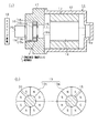
図1は、車両用電動パワーステアリング装置(EPS)用のモータ11を示す。モータ11は、電動パワーステアリング装置の駆動源として備えられ、運転者のステアリング操作をアシストすべくその時々の好適なアシスト力に応じた回転トルクを発生させてステアリング機構10に付与している。本実施形態のモータ11は、ブラシレスモータにて構成されている。
DESCRIPTION OF EXEMPLARY EMBODIMENTS Hereinafter, an embodiment of the invention will be described with reference to the drawings.
FIG. 1 shows a
モータ11において、有底筒状のハウジング12の内周面にはステータ13が固定され、該ステータ13の内側にはロータ14が収容されている。ロータ14は、該ロータ14に備えられるモータ回転軸15がハウジング12の底部中央に備えられる軸受16aと該ハウジング12の開口部を閉塞するエンドフレーム17の中央部に備えられる軸受16bとで回転可能に支持されている。
In the
エンドフレーム17にはレゾルバステータ18aが備えられ、これに対応してモータ回転軸15にはレゾルバロータ18bが備えられ、これらによりロータ14(モータ回転軸15)の回転角を検出する回転角センサ18が構成されている。本実施形態の回転角センサ18は、軸倍角4Xにて構成されている。回転角センサ18ではロータ14の回転角が検出され、該検出に基づいてステータ13のコイル(図示略)への駆動電流が制御されている。ロータ14の1回転における電気角周期が4周期となるコイルの磁極数となっている。また、回転角センサ18によるロータ14の回転角の検出に基づき、本実施形態の電動パワーステアリング装置ではステアリングの舵角検出も行われている。
The
回転角センサ18より先端側のモータ回転軸15には、磁気継手よりなる磁気クラッチ機構19を介して出力軸20が同軸上に駆動連結されている。磁気クラッチ機構19は、モータ回転軸15の先端部に固定される入力側の磁気吸着部19aと、出力軸20の基端部に固定される出力側の磁気吸着部19bとを備えてなり、各吸着部19a,19bは、マグネットを有して円盤状をなし、磁気吸着力が軸方向に作用するように構成されている。各磁気吸着部19a,19bは、軸方向の対向面上においてそのマグネットのN極とS極とが交互に等角度間隔に8磁極が構成され、N極とS極との組が4組構成されている(極対数が「4」)。
An
そして、このような磁気クラッチ機構19を有するモータ11は、該クラッチ機構19の各磁気吸着部19a,19bが吸着していることで、モータ11の駆動に基づくモータ回転軸15の回転が出力軸20からステアリング機構10に伝達されて、ステアリング操作のアシストに必要な回転トルクが伝達される。
In the
また、そのステアリング操作時において該ステアリングの回転端当て時や反転操作時等の負荷変動が大きい場合には、ステアリング機構10と連結する出力軸20と、モータ11(ロータ14)の慣性力が作用するモータ回転軸15との間において、衝撃の要因となる大きな回転力の差が生じる。このような場合、クラッチ機構19では、各磁気吸着部19a,19bの磁気吸着力に抗して各吸着部19a,19b、即ち出力軸20とモータ回転軸15との間で相対回転(滑り)が生じ、運転者に不快となる衝撃の緩和がなされるようになっている。
When the steering operation is large, such as when the steering end of the steering wheel is rotated or when the load is reversed, the inertia force of the
しかもこの場合、磁気クラッチ機構19の各磁気吸着部19a,19bの磁極対数は「4」であり、回転角センサ18の軸倍角4Xと同数(ロータ14の電気角周期の4周期と同数)にて構成されていることから、各吸着部19a,19bにて滑りが生じても、再吸着後の位置は常にロータ14の電気角1周期毎の位置である。そのため、滑りが生じても回転角センサ18にて検出の電気角位置と出力軸20の位置(ステアリングの位置)との対応付けが不変であるため、該機構19の入力側に位置する回転角センサ18であってもステアリングの舵角検出を的確に行うことが可能である。
In addition, in this case, the number of magnetic pole pairs of each of the magnetic attracting
次に、本実施形態の特徴的な作用効果を記載する。
(1)本実施形態では、磁気クラッチ機構19(磁気吸着部19a,19b)の磁極対数が回転角センサ18の軸倍角(ロータ14の1回転における電気角周期数)と同数に設定されている。そのため、負荷変動が大きくなった場合の出力軸20側と慣性力の作用するロータ14側との回転力の差が大きく磁気クラッチ機構19の各磁気吸着部19a,19b間で相対回転(滑り)が生じても、各吸着部19a,19bの再吸着後の位置は常にロータ14の電気角1周期分ずれた位置となる。尚、本実施形態では、互いに同数に設定されることから、滑りに対する回転角センサ18の検出の電気角位置と出力軸20の位置との電気角周期単位のズレが最小となっている。そのため、磁気クラッチ機構19にて滑りが生じても回転角センサ18にて検出の電気角位置と出力軸20の位置との対応付けを不変とでき、相互間のズレを防止することができる。
Next, characteristic effects of the present embodiment will be described.
(1) In the present embodiment, the number of magnetic pole pairs of the magnetic clutch mechanism 19 (magnetic attracting
特に本実施形態のような車両用電動パワーステアリング装置では、ステアリングの回転端当て時や反転操作時等、大きな負荷変動が生じ易く、またモータ11の回転角センサ18にてステアリングの舵角検出が行われていることから、磁気クラッチ機構19にて滑りが生じた際の回転角センサ18の検出の電気角位置と出力軸20の位置とのズレが防止されることで、該機構19の入力側に位置する回転角センサ18であってもステアリングの舵角検出を的確に行うことができる。
In particular, in the electric power steering apparatus for a vehicle as in the present embodiment, a large load fluctuation is likely to occur when the steering end of the steering wheel is turned or when the steering operation is reversed, and the steering angle of the steering is detected by the
(2)本実施形態では、磁気クラッチ機構19は、各磁気吸着部19a,19bを円盤状とし、磁気吸着力が軸方向に作用するように構成されている。これにより、磁気クラッチ機構19を簡素に構成でき、モータ11の構成の簡素化・小型化に寄与することができる。
(2) In the present embodiment, the magnetic
尚、本発明の実施形態は、以下のように変更してもよい。
・上記実施形態では、磁気クラッチ機構19の各磁気吸着部19a,19bを磁気吸着力が軸方向に作用するように構成したが、これに限定されるものではなく、例えば図2に示すように、磁極が等角度間隔に構成された各磁気吸着部19a,19bを円筒状に構成して磁気吸着部19aをモータ回転軸15の外周面に固着、磁気吸着部19bを出力軸20の内周面に固着し、磁気吸着力が径方向に作用するように構成してもよい。この構成でも、磁気クラッチ機構19を簡素に構成でき、モータ11の構成の簡素化・小型化に寄与できる。
In addition, you may change embodiment of this invention as follows.
In the above embodiment, the magnetic attracting
・上記実施形態では、磁気吸着部19a,19bの磁極対数を「4」、回転角センサ18の軸倍角を4X(ロータ14の1回転の電気角周期を4周期)としたが、これらの数に限定されるものではなく適宜変更してもよい。尚、磁気吸着部19a,19bの磁極対数と回転角センサ18の軸倍角とを同数に設定すれば、上記実施形態で述べたように、各吸着部19a,19bの滑りは常にロータ14の電気角1周期分である。またそれ以外でも、磁気吸着部19a,19bの磁極対数を回転角センサ18の軸倍角の約数に設定してもよく、この場合、各吸着部19a,19bの滑りは常にロータ14の電気角1周期の倍数単位となり、同様にステアリングの舵角検出を的確に行うことが可能である。
In the above embodiment, the number of magnetic pole pairs of the magnetic attracting
・上記実施形態では、磁気クラッチ機構19とモータ回転軸15及び出力軸20と直接的に連結する構成であったが、磁気クラッチ機構19と各軸15,20との間に他の駆動伝達機構、例えば減速機構等が介在されていてもよい。
In the above embodiment, the magnetic
・上記実施形態では、電動パワーステアリング装置用のモータ11に適用したが、該装置以外の駆動源として用いるモータに適用してもよい。
次に、上記実施形態及び別例から把握できる技術的思想を以下に追記する。
In the above embodiment, the present invention is applied to the
Next, a technical idea that can be grasped from the above embodiment and another example will be added below.
(イ) 請求項1〜4のいずれか1項に記載のモータをその駆動源として構成されたことを特徴とする車両用電動パワーステアリング装置。
この構成によれば、請求項1〜4のいずれか1項に記載のモータがその駆動源として車両用電動パワーステアリング装置が構成される。つまり、該装置では、ステアリングの回転端当て時や反転操作時等、大きな負荷変動が生じ易く、またモータの回転角センサにてステアリングの舵角検出が行われるものもあることから、磁気クラッチ機構にて滑りが生じた際の回転角センサ検出の電気角位置と出力軸の位置とのズレが防止されることで、該機構の入力側に位置する回転角センサであってもステアリングの舵角検出を的確に行うことが可能となる。
(A) An electric power steering apparatus for a vehicle, wherein the motor according to any one of claims 1 to 4 is used as a drive source.
According to this configuration, the electric power steering device for a vehicle is configured with the motor according to any one of claims 1 to 4 as a drive source. That is, in such a device, a large load fluctuation is likely to occur at the time of turning the steering end of the steering wheel or during a reversing operation, and the steering angle of the steering is detected by the rotation angle sensor of the motor. This prevents the deviation between the electrical angle position detected by the rotation angle sensor and the output shaft position when slippage occurs at the steering angle, so that even if the rotation angle sensor is located on the input side of the mechanism, the steering angle of the steering wheel Detection can be performed accurately.
10…ステアリング機構(駆動対象)、11…モータ、14…ロータ、18…回転角センサ、19…磁気クラッチ機構、19a,19b…磁気吸着部、20…出力軸。
DESCRIPTION OF
Claims (5)
前記磁気クラッチ機構の磁極対数と前記回転角センサの軸倍角とは、その磁極対数が軸倍角の約数に設定されたことを特徴とするモータ。 The rotation of the rotor is transmitted to the output shaft by magnetic connection between the magnetic attracting portion on the rotor side and the magnetic attracting portion on the output shaft side. On the other hand, if the difference in rotational force between the output shaft side and the rotor side increases The motor includes a magnetic clutch mechanism that allows relative rotation between the magnetic attraction portions against an attraction force, and a rotation angle sensor that detects the rotation angle of the rotor and the position of the drive target of the output shaft. And
The motor characterized in that the number of magnetic pole pairs of the magnetic clutch mechanism and the shaft angle multiplier of the rotation angle sensor are set to a divisor of the shaft angle multiplier.
前記磁気クラッチ機構の磁極対数と前記回転角センサの軸倍角とは、同数に設定されたことを特徴とするモータ。 The motor according to claim 1,
The motor according to claim 1, wherein the number of magnetic pole pairs of the magnetic clutch mechanism and the shaft angle multiplier of the rotation angle sensor are set to the same number.
前記磁気クラッチ機構は、前記ロータ側の磁気吸着部と前記出力軸側の磁気吸着部とをそれぞれ円盤状とし、磁気吸着力が軸方向に作用するように構成されたことを特徴とするモータ。 The motor according to claim 1 or 2,
The motor is characterized in that the magnetic clutch mechanism is configured such that the magnetic attracting portion on the rotor side and the magnetic attracting portion on the output shaft side are respectively disk-shaped, and the magnetic attracting force acts in the axial direction.
前記磁気クラッチ機構は、前記ロータ側の磁気吸着部と前記出力軸側の磁気吸着部とをそれぞれ円筒状とし、磁気吸着力が径方向に作用するように構成されたことを特徴とするモータ。 The motor according to claim 1 or 2,
2. The motor according to claim 1, wherein the magnetic clutch mechanism is configured such that the rotor-side magnetic attracting portion and the output shaft-side magnetic attracting portion are cylindrical, and the magnetic attracting force acts in the radial direction.
車両用電動パワーステアリング装置の駆動源として用いられることを特徴とするモータ。 The motor according to any one of claims 1 to 4,
A motor used as a drive source of an electric power steering device for a vehicle.
Priority Applications (1)
| Application Number | Priority Date | Filing Date | Title |
|---|---|---|---|
| JP2009044553A JP2010200543A (en) | 2009-02-26 | 2009-02-26 | Motor |
Applications Claiming Priority (1)
| Application Number | Priority Date | Filing Date | Title |
|---|---|---|---|
| JP2009044553A JP2010200543A (en) | 2009-02-26 | 2009-02-26 | Motor |
Publications (1)
| Publication Number | Publication Date |
|---|---|
| JP2010200543A true JP2010200543A (en) | 2010-09-09 |
Family
ID=42824655
Family Applications (1)
| Application Number | Title | Priority Date | Filing Date |
|---|---|---|---|
| JP2009044553A Pending JP2010200543A (en) | 2009-02-26 | 2009-02-26 | Motor |
Country Status (1)
| Country | Link |
|---|---|
| JP (1) | JP2010200543A (en) |
Cited By (2)
| Publication number | Priority date | Publication date | Assignee | Title |
|---|---|---|---|---|
| DE102015102140A1 (en) * | 2015-02-13 | 2016-08-18 | Terex MHPS IP Management GmbH | Arrangement of an electric drive motor, a transmission and a rotary encoder, in particular for a cable pull |
| WO2017119616A1 (en) * | 2016-01-07 | 2017-07-13 | 엘지이노텍 주식회사 | Device for detecting position of rotor, and motor comprising same |
-
2009
- 2009-02-26 JP JP2009044553A patent/JP2010200543A/en active Pending
Cited By (6)
| Publication number | Priority date | Publication date | Assignee | Title |
|---|---|---|---|---|
| DE102015102140A1 (en) * | 2015-02-13 | 2016-08-18 | Terex MHPS IP Management GmbH | Arrangement of an electric drive motor, a transmission and a rotary encoder, in particular for a cable pull |
| US10202264B2 (en) | 2015-02-13 | 2019-02-12 | Konecranes Global Corporation | Cable winch |
| WO2017119616A1 (en) * | 2016-01-07 | 2017-07-13 | 엘지이노텍 주식회사 | Device for detecting position of rotor, and motor comprising same |
| KR20170082894A (en) * | 2016-01-07 | 2017-07-17 | 엘지이노텍 주식회사 | Detecting device for sensing the rotor position and motor having the same |
| US10910921B2 (en) | 2016-01-07 | 2021-02-02 | Lg Innotek Co., Ltd. | Device for detecting position of rotor, and motor comprising same |
| KR102542138B1 (en) | 2016-01-07 | 2023-06-12 | 엘지이노텍 주식회사 | Detecting device for sensing the rotor position and motor having the same |
Similar Documents
| Publication | Publication Date | Title |
|---|---|---|
| KR20060053865A (en) | Stabilizer control device | |
| WO2012096308A1 (en) | Motor drive force transmission device | |
| JP4433022B2 (en) | Electric motor | |
| JP2008505007A5 (en) | ||
| US20130162112A1 (en) | Motor-Gear Unit | |
| JP2014523363A5 (en) | ||
| JP2008540209A5 (en) | ||
| JP2012117673A (en) | Driving system | |
| JP2012213308A5 (en) | ||
| JP7061055B2 (en) | Steering device | |
| JP2009106125A (en) | Motor rotation angle detection device | |
| JP2009162268A (en) | Shift range switching device | |
| JP4872229B2 (en) | Vehicle steering system | |
| JP2010200543A (en) | Motor | |
| JP2013129311A (en) | Motor drive force transmission device | |
| JP2013226880A (en) | Reduction gear of electric power steering device | |
| JP5883693B2 (en) | Reduction device for electric power steering device | |
| JP2006050816A (en) | Brushless motor | |
| JPS6343869A (en) | Servo steering gear | |
| JP2018038147A (en) | Electric power steering motor and electric power steering device | |
| JPH06344927A (en) | Motor-driven power steering device | |
| JP7052387B2 (en) | Electric gear pump | |
| JP5973141B2 (en) | Brushless motor and electric power steering device using the same | |
| JP2009293789A (en) | Stabilizer control device | |
| JP2004360732A (en) | Electric power steering device |