JP2010197279A - Navigation system and program for navigation - Google Patents
Navigation system and program for navigation Download PDFInfo
- Publication number
- JP2010197279A JP2010197279A JP2009043791A JP2009043791A JP2010197279A JP 2010197279 A JP2010197279 A JP 2010197279A JP 2009043791 A JP2009043791 A JP 2009043791A JP 2009043791 A JP2009043791 A JP 2009043791A JP 2010197279 A JP2010197279 A JP 2010197279A
- Authority
- JP
- Japan
- Prior art keywords
- gps
- candidate point
- cost
- distance
- road
- Prior art date
- Legal status (The legal status is an assumption and is not a legal conclusion. Google has not performed a legal analysis and makes no representation as to the accuracy of the status listed.)
- Granted
Links
Images
Classifications
-
- G—PHYSICS
- G01—MEASURING; TESTING
- G01C—MEASURING DISTANCES, LEVELS OR BEARINGS; SURVEYING; NAVIGATION; GYROSCOPIC INSTRUMENTS; PHOTOGRAMMETRY OR VIDEOGRAMMETRY
- G01C21/00—Navigation; Navigational instruments not provided for in groups G01C1/00 - G01C19/00
- G01C21/26—Navigation; Navigational instruments not provided for in groups G01C1/00 - G01C19/00 specially adapted for navigation in a road network
- G01C21/28—Navigation; Navigational instruments not provided for in groups G01C1/00 - G01C19/00 specially adapted for navigation in a road network with correlation of data from several navigational instruments
- G01C21/30—Map- or contour-matching
Landscapes
- Engineering & Computer Science (AREA)
- Radar, Positioning & Navigation (AREA)
- Remote Sensing (AREA)
- Automation & Control Theory (AREA)
- Physics & Mathematics (AREA)
- General Physics & Mathematics (AREA)
- Navigation (AREA)
- Instructional Devices (AREA)
Abstract
Description
本発明は、ナビゲーション装置及びナビゲーション用プログラムに係り、詳細にはナビゲーションにおけるマップマッチングに関する。 The present invention relates to a navigation device and a navigation program, and more particularly to map matching in navigation.
車両に搭載されて目的地までの走行経路を探索して車両を案内するナビゲーション装置が広く普及している。
このナビゲーション装置では、車両の現在位置を特定し、車両の現在位置を地図上に表示したり、走行の案内をしたりしている。
現在位置の特定にはジャイロ・車速パルス・加速度センサといったセンサ類が使用されており、それらの情報から推測航法により推測軌跡を作成する。推測軌跡とDBに格納した道路情報とで形状マッチングを行い、一致した位置を現在位置として特定し、特定した現在位置に自車位置を表す現在位置マークを表示している。
マッチングの方法としては各種情報からマッチング候補毎に確からしさを表すコスト値を付与し、コスト値の比較により最も小さいコスト値のマッチング候補位置にマッチングする。
2. Description of the Related Art Navigation devices that are mounted on vehicles and that guide a vehicle by searching for a travel route to a destination are widely used.
In this navigation device, the current position of the vehicle is specified, the current position of the vehicle is displayed on a map, and travel guidance is provided.
Sensors such as a gyro, a vehicle speed pulse, and an acceleration sensor are used to specify the current position, and an estimated locus is created from the information by dead reckoning navigation. Shape matching is performed between the estimated trajectory and the road information stored in the DB, the matched position is identified as the current position, and a current position mark representing the vehicle position is displayed at the identified current position.
As a matching method, a cost value indicating the certainty is assigned to each matching candidate from various information, and matching is performed to a matching candidate position having the smallest cost value by comparing the cost values.
一方、車両の絶対位置(緯度、経度)を測定するためにGPSが用いられているが、GPS情報は、GPS精度が高い場合における上記センサの学習に用い、通常の現在位置の更新の際の位置補正等には常に使用されるわけではない。これは、GPSの弱点としてマルチパス等の影響で精度が悪化する場合があるためである。 On the other hand, GPS is used to measure the absolute position (latitude, longitude) of the vehicle, but the GPS information is used for learning the sensor when the GPS accuracy is high, and is used when updating the normal current position. It is not always used for position correction. This is because the accuracy may deteriorate due to the influence of multipath or the like as a weak point of GPS.
このような、推測航法による現在位置の特定では、例えば、複数本の道路のなす角度が所定角以下の狭い角度で分岐(狭角分岐)している場合等に、次のような理由で現在位置の誤マッチングが発生しやすい。
道路種別やリンク形状等から判断された道なりの道路はマッチングの際に優先されるため、道なりの道路とは別の道路に自車が進行した場合には結果として誤マッチングとなってしまう。
また、推測軌跡の方位誤差によって誤った道路へ誤マッチングしてしまうことがある。
更に、実際には幅のある道路をDBでは線(リンク)で表現しているため、実際の走行経路とリンク形状とで一致しない場合があり、推測軌跡とリンク形状を比較しても正しい道路へマッチングさせることが出来ないことがある。
In the case of specifying the current position by dead reckoning navigation, for example, when the angle formed by a plurality of roads branches at a narrow angle of a predetermined angle or less (narrow angle branch), the current position is determined for the following reason. Mismatching of position is likely to occur.
Since roads determined by road type, link shape, etc. are prioritized during matching, if the vehicle travels on a different road from the road, it will result in incorrect matching. .
In addition, an incorrect road may be erroneously matched due to an orientation error of the estimated trajectory.
In addition, since a wide road is actually represented by a line (link) in the DB, the actual travel route may not match the link shape, and the correct road even if the estimated trajectory and the link shape are compared. May not be able to match.
さらに狭角分岐において誤マッチングしてしまうと、次の理由により復帰(正しい道路へのマッチング)が遅れる場合があった。
すなわち、狭角分岐後の両道路がほぼ平行になっている場合は推測軌跡とリンク形状を比較しても差異がないため、正しい道路へマッチングを復帰させることが困難である。
また、表示用推測軌跡が誤マッチングしたリンクに重なるように補正されることがあり、その場合正しい道路への復帰がさらに困難になる。
Furthermore, if there is a false matching at a narrow-angle branch, the return (matching to the correct road) may be delayed for the following reason.
That is, when both roads after narrow-angle branching are almost parallel, there is no difference even if the estimated trajectory is compared with the link shape, and it is difficult to return matching to the correct road.
In addition, the display estimated trajectory may be corrected so as to overlap the erroneously matched link, and in this case, it becomes more difficult to return to the correct road.
このような狭角分岐後の誤マッチングを回避するためにGPSの測位点を用いる技術が特許文献1で提案されている。
この特許文献1では、GPS測位点を中心とし、DOP(測位精度低下率)に応じてた誤差半径の誤差円を設定し、誤差円の範囲内に検出した自車位置が含まれていれば正しいものとみなしている。
そして、分岐点を通過した場合には、この誤差円を分岐点から段階的に小さくすることで、誤マッチングした場合の候補地点が早めに誤差円から外れることで、正しい道路に復帰させるようにしてる。
A technique using a GPS positioning point is proposed in
In this
And when passing through a branch point, this error circle is made smaller from the branch point step by step, so that the candidate point in the case of incorrect matching deviates from the error circle earlier, so that it returns to the correct road. I'm.
しかし、特許文献1記載技術では、実際の道路に対する幅員を考慮していず、道路データのリンク形状が誤差円に含まれるか否かを判断対象としている。
このため、実際の車両はリンクから外れた幅員の範囲内で走行している場合であっても、リンクが誤差円から外れた場合には誤マッチングと判断してしまうという問題がある。
However, the technique described in
For this reason, even if the actual vehicle is traveling within the range of the width deviated from the link, there is a problem that if the link deviates from the error circle, it is determined as an incorrect matching.
本発明は、より誤マッチングを少なくすると共に、誤マッチングから早期に回復することを目的とする。 An object of the present invention is to reduce false matching more and to recover from false matching at an early stage.
(1)請求項1記載の発明では、道路上に設定した候補地点に対するコスト計算により最有力候補地点を特定し、特定した最有力候補地点に車両位置をマッチングさせるナビゲーション装置であって、推測航法により車両の推測位置を取得する推測位置取得手段と、GPSにより車両のGPS位置を取得するGPS位置取得手段と、前記推測位置の周辺に存在する道路上に車両位置の候補地点を設定する候補地点設定手段と、前記推測位置に対する候補地点の通常コストを前記各候補地点に対して算出する通常コスト算出手段と、前記GPS位置と候補地点の距離dから、前記候補地点が設定されている道路の幅員Wを減算した値L1に応じた補正コストを前記各候補地点に対して算出する補正コスト算出手段と、狭角分岐点を通過したか否かを判断する狭角分岐通過判断手段と、前記狭角分岐通過したと判断した場合に、前記各候補地点に対する前記通常コストと前記補正コストとの合計コストから最有力候補地点を特定する、最有力候補地点特定手段と、を具備したことを特徴とするナビゲーション装置を提供する。
(2)請求項2記載の発明では、前記最有力候補地点特定手段は、狭角分岐通過後所定距離の間、各候補地点に対して累積的に補正コストを加算する、ことを特徴とする請求項1に記載のナビゲーション装置を提供する。
(3)請求項3記載の発明では、前記GPS位置に対する誤差範囲の距離を示す想定最大誤差eを取得する想定最大誤差算出手段と、前記値L1から前記値前記想定最大誤差eを減算した値L2を算出する算出手段と、を備え、前記補正コスト算出手段は、前記値L2がマイナスである場合、前記値L1に第1比例定数を乗じた値を補正コストとし、前記値L2がプラスである場合、前記値L2に前記第1比例定数よりも大きな第2比例定数を乗じた値と、前記想定最大誤差eに第1比例定数を乗じた値とを加算した値を補正コストとする、ことを特徴とする請求項1又は請求項2に記載のナビゲーション装置を提供する。
(4)請求項4記載の発明では、前記補正コスト算出手段は、前記値L1がマイナスである場合には、補正コストをゼロとすることを特徴とする請求項1、請求項2、又は請求項3に記載のナビゲーション装置を提供する。
(5)請求項5記載の発明では、前記想定最大誤差eは、前記GPSのDOPに基づく誤差円の半径であることを特徴とする請求項3に記載のナビゲーション装置を提供する。
(6)請求項6記載の発明では、前記想定最大誤差eは、DOP、前記推測位置とGPS位置間の距離、及び推測位置の軌跡による方位とGPS位置の軌跡による方位の差から算出した信頼度に応じた距離であることを特徴とする請求項3に記載のナビゲーション装置を提供する。
(7)請求項7記載の発明では、前記設定した全候補地点に対する重心点を算出する重心点算出手段、を備え、前記候補地点設定手段は、前記重心点と前記GPS位置との進行方向の距離が所定値を越える場合に、前記各候補地点を進行方向前後に補正する、ことを特徴とする請求項1から請求項6のうちのいずれか1つの請求項に記載したナビゲーション装置を提供する。
(8)請求項8記載の発明では、道路上に設定した候補地点に対するコスト計算により最有力候補地点を特定し、特定した最有力候補地点に車両位置をマッチングさせるナビゲーション用プログラムであって、推測航法により車両の推測位置を取得する推測位置取得機能と、GPSにより車両のGPS位置を取得するGPS位置取得機能と、前記推測位置の周辺に存在する道路上に車両位置の候補地点を設定する候補地点設定機能と、前記推測位置に対する候補地点の通常コストを前記各候補地点に対して算出する通常コスト算出機能と、前記GPS位置と候補地点の距離dから、前記候補地点が設定されている道路の幅員Wを減算した値L1に応じた補正コストを前記各候補地点に対して算出する補正コスト算出機能と、前記各候補地点に対する前記通常コストと前記補正コストとの合計コストから最有力候補地点を特定する、最有力候補地点特定機能と、をコンピュータに実現させることを特徴とするナビゲーション用プログラムを提供する。
(1) The invention according to
(2) The invention according to
(3) In the invention according to
(4) In the invention according to
(5) The navigation device according to
(6) In the invention according to
(7) The invention according to
(8) The invention according to
本発明によれば、道路上に設定した候補地点に対するコスト計算により最有力候補地点を特定する場合に、GPS位置と各候補地点の距離dと道路の幅員Wを考慮したコスト計算により最有力候補地点を特定しているので、誤マッチングが少なくなると共に、誤マッチングした場合であっても早期に回復することができる。 According to the present invention, when the most probable candidate point is specified by cost calculation for the candidate point set on the road, the most probable candidate is calculated by cost calculation in consideration of the GPS position, the distance d of each candidate point, and the width W of the road. Since the point is specified, there is less mismatching, and even if there is a mismatch, it can be recovered early.
以下、本発明のナビゲーション装置及びナビゲーション用プログラムにおける好適な実施の形態について、図1から図12を参照して詳細に説明する。
(1)実施形態の概要
本実施形態のナビゲーション装置では、狭角分岐通過時に推測航法だけで確実に正しい道路にマッチングさせることは難しいため、各候補地点のコスト計算において、通常のコスト計算による通常コストに、GPS座標からの距離に応じたGPSコスト(補正コスト)を加算することで速やかに正しい道路にマッチングを復帰させる。
このとき、GPS座標には誤差があり、また、幅の広い道路では車両がDBリンクから離れた位置を走行していることも考えられるため、GPSの信頼度および幅員を加味してコストを算出する。
Hereinafter, preferred embodiments of the navigation device and the navigation program of the present invention will be described in detail with reference to FIGS.
(1) Outline of Embodiment In the navigation device of this embodiment, it is difficult to reliably match a correct road only by dead reckoning navigation when passing through a narrow-angle branch. By matching the cost with the GPS cost (correction cost) corresponding to the distance from the GPS coordinates, matching is quickly returned to the correct road.
At this time, there is an error in the GPS coordinates, and it is also possible that the vehicle is traveling away from the DB link on a wide road, so the cost is calculated taking into account the reliability and width of the GPS. To do.
マップマッチングにおける通常コストは次のように計算される。
すなわち、距離センサと相対方位センサにより車両の移動距離と走行の方位を検出し、地図データ上の現在位置(推測位置)を推定し(推測航法)、推定位置から所定距離範囲内に存在する各道路上に設定されている前回の候補地点を車両の移動距離に応じて移動させる。そして、推定位置から各候補地点までの距離や方位などをパラメータとして各候補地点に対する通常コストを計算する。
The normal cost for map matching is calculated as follows.
In other words, the distance traveled by the distance sensor and the relative bearing sensor detect the travel distance and travel direction of the vehicle, estimate the current position (estimated position) on the map data (estimated navigation), and each existing within a predetermined distance range from the estimated position The previous candidate point set on the road is moved according to the moving distance of the vehicle. Then, the normal cost for each candidate point is calculated using the distance, direction, and the like from the estimated position to each candidate point as parameters.
一方、GPSの信頼度については、DOPに基づく誤差円を使用するようにしてもよいが、本実施形態では、GPSの信頼度を用いてより精度を高くしている。すなわち、DOPに加えて、推測軌跡による車両位置とGPS位置間の距離(距離の一致度)、及び推測軌跡による方位とGPS方位の一致度を考慮することで、誤差の範囲をより精度良く求め、誤差範囲をより小さくした、信頼度円(半径=想定最大誤差e)を使用する。
GPS位置までの距離dが幅員W以下の候補地点については当該候補地点を設定した道路上を走行している可能性が高いのでGPSコスト(補正コスト)を0とし、距離dが幅員Wよりも大きい候補地点に対しては距離dに応じて大きくなるGPSコストを加算する。
GPSコストは、候補地点からその道路の幅員Wだけ離れた点(幅員点)wが信頼度円内に存在する場合にはGPS位置と幅員点wとの距離L1に応じたGPSコストk1を加算する。
また、幅員点wが信頼度円内に存在しない場合には、距離L1=想定最大誤差eとした場合のGPSコストk1(候補地点が信頼度円上に位置する場合のコストk1)に加え、更に幅員点wから信頼度円までの距離L2に応じたGPSコストk2を加算する。ただし、GPSコストk2には、GPSコストが極端に大きくなることを防止するために上限が設けられている。これにより、コストが所定値を超えた候補地点は候補対象から除外されるが、極端に大きなGPSコストが累積加算されて、候補対象からすぐに外れてしまうことが回避される。
On the other hand, for the GPS reliability, an error circle based on DOP may be used, but in the present embodiment, the accuracy is increased by using the GPS reliability. In other words, in addition to DOP, the distance between the vehicle position and the GPS position by the estimated trajectory (distance coincidence), and the azimuth and GPS azimuth degree by the estimated trajectory are taken into account, so that the error range can be obtained more accurately. A reliability circle (radius = assumed maximum error e) with a smaller error range is used.
For a candidate point whose distance d to the GPS position is less than or equal to the width W, it is highly likely that the vehicle is traveling on the road where the candidate point is set, so the GPS cost (correction cost) is set to 0 and the distance d is greater than the width W. For a large candidate point, a GPS cost that increases according to the distance d is added.
The GPS cost is calculated by adding the GPS cost k1 corresponding to the distance L1 between the GPS position and the width point w when a point (width point) w away from the candidate point by the width W of the road exists in the reliability circle. To do.
In addition, when the width point w does not exist in the reliability circle, in addition to the GPS cost k1 when the distance L1 = the assumed maximum error e (cost k1 when the candidate point is located on the reliability circle), Further, a GPS cost k2 corresponding to the distance L2 from the width point w to the reliability circle is added. However, the GPS cost k2 has an upper limit for preventing the GPS cost from becoming extremely large. As a result, candidate points whose costs exceed a predetermined value are excluded from the candidate targets, but it is avoided that extremely large GPS costs are cumulatively added and immediately deviated from the candidate targets.
また、変形例では、分岐に到達するタイミングが実際と異なっていると、リンクと表示用推測軌跡の比較が適切に行われないため、前後位置を補正するために、GPS座標とマッチング候補の重心を比較して差分がある場合にはマッチング候補の更新間隔を変化させて徐々に位置補正させる。 Also, in the modified example, if the timing of reaching the branch is different from the actual one, the link and the display estimated trajectory are not properly compared. If there is a difference, the update interval of the matching candidate is changed and the position is gradually corrected.
(2)実施形態の詳細
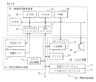
図1は本実施形態が適用されるナビゲーション装置のシステム構成図である。
このナビゲーション装置は、車両に搭載され、この図1に示すように、現在位置検出装置10、情報処理制御装置20、入出力装置40及び情報記憶装置50とを備えている。
(2) Details of Embodiment FIG. 1 is a system configuration diagram of a navigation apparatus to which this embodiment is applied.
The navigation device is mounted on a vehicle and includes a current
現在位置検出装置10は、以下のような構成を有している。
方位センサ12は、基準角度(絶対方位)に対して、相対的に変化した角度を検出する手段であり、本実施形態では、角速度を利用して角度の変化を検出するジャイロセンサを使用している。なお、ハンドルの回転部に取り付けた光学的な回転センサや回転型の抵抗ボリューム或いは車輪部に取り付ける角度センサでもよい。また、方位センサ12として、例えば、磁石に基づいてN方向の検出から、車両がいずれの方向に位置するかを検出する地磁気センサであり、絶対方位を検出する手段であってもよい。
The current
The azimuth sensor 12 is a means for detecting an angle that has changed relative to a reference angle (absolute azimuth). In this embodiment, a gyro sensor that detects a change in angle using an angular velocity is used. Yes. Note that an optical rotation sensor attached to the rotating part of the handle, a rotary resistance volume, or an angle sensor attached to the wheel part may be used. Further, the direction sensor 12 may be, for example, a geomagnetic sensor that detects in which direction the vehicle is located from detection in the N direction based on a magnet, and may be a means for detecting an absolute direction.
距離センサ13は、車両の移動距離を計測できる手段であり、例えば、車輪の回転を検出して計数するものや、加速度を検出して2回積分するものを使用する。
GPS(グローバル・ポジショニング・システム)受信装置14は、人工衛星からの信号を受信する装置であり、信号の発信時刻、受信装置の位置情報、受信装置の移動速度、受信装置の進行方向など様々な情報を得ることができる。
The distance sensor 13 is a means that can measure the moving distance of the vehicle, and for example, a sensor that detects and counts the rotation of a wheel or a sensor that detects acceleration and integrates it twice.
The GPS (Global Positioning System)
次に、情報処理制御装置20は、現在位置検出装置10、入出力装置40から入力される情報及び情報記憶装置50に格納された情報に基づいて演算及び制御を行うとともに、演算結果をディスプレイ42、プリンタ43またはスピーカ44等の出力手段に出力するように制御する手段である。
Next, the information
この情報処理制御装置20は、以下のような構成を有している。
中央処理装置(CPU)21は、ナビゲーション装置全体の総括的な演算及び制御を行う。
ROM22は、目的地までの経路の探索、表示案内や音声案内等のナビゲーションに関するプログラムや、本実施形態による、GPS信頼度と幅員を考慮したコスト計算によるマップマッチング処理プログラム等の各種プログラムを格納している。なお、ROM22を第1ROMと第2ROMの2つに分け、第2ROMに音声案内に関するナビゲーションプログラムを格納し、他のプログラムを第1ROMに格納するようにしてもよい。
本実施形態のマップマッチングプログラムにおいて、後述する信頼度データが定義されているが、プログラムとは独立した信頼度データの参照テーブルを設けプログラムの実行過程で信頼度データを参照するようにしてもよく、また、後述する情報記憶装置50に信頼度データファイルを保存するようにしてもよい。
The information
The central processing unit (CPU) 21 performs overall calculation and control of the entire navigation device.
The
In the map matching program of the present embodiment, reliability data to be described later is defined. However, a reliability data reference table independent of the program may be provided to refer to the reliability data during the execution of the program. Further, the reliability data file may be stored in the information storage device 50 described later.
RAM24は、入力装置41により入力された目的地の情報、通過地点の情報等の利用者が入力した情報を記憶すると共に、利用者の入力情報に基づいてCPU21により演算された結果や、経路探索された結果、または情報記憶装置50から読み込まれた地図情報を格納するための記憶手段である。
また、RAM24には、本実施形態のマップマッチングで使用する、推測位置及び候補地点が一時保存される。
The
The
通信インターフェイス25は、伝送路45を介して各種情報の入出力するための手段である。具体的には、伝送路45を介して、GPS受信装置14、入力装置41、プリンタ43、情報記憶装置50が接続される。
時計28は、時刻を刻む。
その他、CPU21で処理されたベクトル情報を画像情報に処理するための画像処理専用の画像プロセッサ、画像プロセッサで処理された画像情報を格納する画像メモリ、情報記憶装置50から読み込まれた音声情報を処理しスピーカ44に出力する音声処理専用の音声プロセッサを配設するようにしてもよい。
The
The
In addition, an image processor dedicated to image processing for processing vector information processed by the
入出力装置40は、利用者により目的地、通過地点、探索条件等のデータを入力する入力装置41、画像を表示するディスプレイ42、情報を印刷するプリンタ43、音声を出力するスピーカ44より構成される。
入力装置41は、例えば、タッチパネル、タッチスイッチ、ジョイスティック、キースイッチ等で構成される。
ディスプレイ42には、現在地周辺の地図や、目的地までの走行経路が表示される。
なお、入出力装置40は、プリンタ43を有しない構成としてもよい。
The input /
The
The
Note that the input /
情報記憶装置50は、伝送路45を介して情報処理制御装置20に接続される。
情報記憶装置50は、地図データファイル51、その他のデータファイル52を格納している。
この情報記憶装置50は、一般的には、光学的記憶媒体であるDVD−ROM、CD−ROMや磁気的記憶媒体であるハードディスクなどで構成されるが、光磁気ディスク、各種半導体メモリなどの各種情報記憶媒体で構成してもよい。
なお、書き換えが必要な情報については、書き換え可能なハードディスク、フラッシュメモリなどで構成し、その他の固定的な情報についてはCD−ROM、DVD−ROMなどのROMを使用するようにしてもよい。
The information storage device 50 is connected to the information
The information storage device 50 stores a
The information storage device 50 is generally composed of an optical storage medium such as a DVD-ROM, a CD-ROM, or a magnetic storage medium such as a hard disk, but various types such as a magneto-optical disk and various semiconductor memories. You may comprise with an information storage medium.
Information that needs to be rewritten may be constituted by a rewritable hard disk or flash memory, and other fixed information may be a ROM such as a CD-ROM or DVD-ROM.
地図データファイル51には、ナビゲーションにおける地図表示、経路探索、経路案内に必要な各種データとして、地図データ、道路データ、目的地データ、案内地点データ、その他のデータが記憶されている。
地図データとしては、全国道路地図、各地域の道路地図または住宅地図等が記憶されている。道路地図は、主要幹線道路、高速道路、細街路等の各道路と地上目標物(施設等)から構成される。住宅地図は、地上建造物等の外形を表す図形及び、道路名称等が表示される市街図である。細街路とは、例えば、国道、県道以下の道幅が所定値以下の比較的狭い道路である。
地図データは、車両現在位置やユーザに指定された地点を含む、所定縮尺による一定範囲の地図がディスプレイ42に表示される。この地図上には、車両の現在位置や指定された地点が表示される。
The map data file 51 stores map data, road data, destination data, guidance point data, and other data as various data necessary for map display, route search, and route guidance in navigation.
As map data, a national road map, a road map of each region, a house map, or the like is stored. The road map is composed of roads such as main arterial roads, expressways, narrow streets, and ground targets (facility etc.). A house map is a city map in which a figure representing an outer shape of a ground building, a road name, and the like are displayed. The narrow street is, for example, a relatively narrow road having a road width equal to or less than a predetermined value below a national road or prefectural road.
As for the map data, a map of a predetermined range including a current vehicle position and a point designated by the user is displayed on the
道路データは、各道路の位置と種類及び車線数及び各道路間の接続関係、本実施形態で使用する道路の幅員、分岐する道路が狭角分岐である場合を示す狭角分岐情報等の道路に関するデータで、ノードデータとリンクデータで構成される。この道路データは、経路探索やマップマッチングに使用されると共に、探索した走行経路を地図データ上に重ねて表示する場合にも使用される。
ノードデータは、地図上において経路探索に利用される各ノードの地理座標データ等を表したデータである。
例えば、交差点などの道路の接続点はノードにより表され、接続点の間の道路(即ち道路の内分岐しない領域)はリンクによって表される。このように、ノードデータ経路の接続関係を表した経路データとして機能している。
なお、進入禁止や一方通行など、交通規制により走行が制限されるものに関しては、これを表す属性が、各リンクに付与されているが、これらの属性については、交差点ノードに付与するようにしてもよい。
ノードデータは、各交差点に対して常に設定される交差点ノードと共に、各交差点間の特徴的な点(例えば、カーブの開始、中間、終了の各地点や、高度が変化する地点など)に補助的に設定される場合がある補助ノードが存在する。交差点ノードには、交差点の地理的位置座標や名称等の交差点に関する情報が含まれる。
The road data includes roads such as narrow-angle branch information indicating the location and type of each road, the number of lanes, the connection relationship between the roads, the width of the road used in this embodiment, and the branch road being a narrow-angle branch. This data is composed of node data and link data. The road data is used for route search and map matching, and is also used when the searched travel route is displayed over the map data.
The node data is data representing geographic coordinate data of each node used for route search on a map.
For example, a road connection point such as an intersection is represented by a node, and a road between the connection points (that is, a non-branching area of the road) is represented by a link. In this way, it functions as route data representing the connection relation of the node data route.
In addition, for those where travel is restricted due to traffic restrictions, such as entry prohibition and one-way traffic, attributes indicating this are given to each link, but these attributes should be given to intersection nodes. Also good.
Node data is supplementary to characteristic points between intersections (for example, points at the start, middle and end of a curve, and points where the altitude changes), along with intersection nodes that are always set for each intersection. There is an auxiliary node that may be set to The intersection node includes information related to the intersection such as the geographical position coordinates and name of the intersection.
目的地データは、主要観光地や建物、電話帳に記載されている企業・事業所等の目的地になる可能性の高い場所や施設等の位置と名称等のデータである。
案内地点データは、道路に設置されている案内表示板の内容や分岐点の案内等、案内が必要とされる地点の案内データである。
The destination data is data such as the locations and names of places and facilities that are likely to be destinations such as major tourist spots, buildings, and companies / businesses described in the telephone directory.
Guidance point data is guidance data of a point where guidance is required, such as the content of a guidance display board installed on a road and guidance of a branch point.
その他のデータファイル52には、例えば、各種施設や観光地、または主要な交差点等の視覚的表示が要求される場所を写した写真の画像データや、設定した走行経路を音声により案内する場合の音声データ等が記憶されている。 The other data file 52 includes, for example, image data of a photograph showing places where visual indications such as various facilities, sightseeing spots, and major intersections are required, and when the set travel route is guided by voice. Audio data and the like are stored.
次に本実施形態のマップマッチングプログラムにおいて、定義されている信頼度データについて説明する。
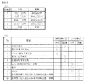
図2は、信頼度の定義と要素について概念的に表したものである。
図2(a)は、本実施形態の信頼度に対する、方位と距離についての想定誤差が規定されている。すなわち、方位に関し、想定方位誤差が1度以内である場合を信頼度5、想定方位誤差が3度以内である場合を信頼度4、想定方位誤差が10度以内である場合を信頼度3、想定方位誤差が45度以内である場合を信頼度2、想定方位誤差が不明である場合を信頼度1と規定している。
Next, reliability data defined in the map matching program of this embodiment will be described.
FIG. 2 conceptually shows the definition and elements of reliability.
FIG. 2A defines an assumed error regarding the direction and the distance with respect to the reliability of the present embodiment. That is, regarding the azimuth, the reliability is 5 when the assumed azimuth error is within 1 degree, the reliability is 4 when the assumed azimuth error is within 3 degrees, and the reliability is 3 when the assumed azimuth error is within 10 degrees. The case where the assumed azimuth error is within 45 degrees is defined as
また距離に関し、想定距離誤差が5m以内である場合を信頼度5、想定距離誤差が10m以内である場合を信頼度4、想定距離誤差が25m以内である場合を信頼度3、想定距離誤差が50m以内である場合を信頼度2、想定距離誤差が不明である場合を信頼度1と規定している。
この想定距離誤差の値が、本実施形態における想定最大誤差e(信頼度円の半径)となる。
Regarding the distance, the reliability is 5 when the assumed distance error is within 5 m, the reliability is 4 when the assumed distance error is within 10 m, the reliability is 3 when the assumed distance error is within 25 m, and the assumed distance error is The case where the distance is within 50 m is defined as
The value of the assumed distance error is the assumed maximum error e (radius of the reliability circle) in the present embodiment.
このように本実施形態では、方位、距離ともに信頼度が5段階に規定されているが、より詳細に規定(例えば、10段階)するようにしてもよい。
なお、想定誤差(方位、距離)については、後述する信頼度の各要素に対する値と、その場合の誤差を実測することで予め規定しておく。
As described above, in the present embodiment, the reliability is defined in five steps for both the azimuth and the distance, but may be defined in more detail (for example, ten steps).
Note that the assumed error (azimuth, distance) is defined in advance by actually measuring the value for each element of reliability described later and the error in that case.
図2(b)は、推測方位と推測距離の信頼度と、GPSによる方位と距離の信頼度を決定するための要素について表したものである。
この図に示されるように、推測信頼度(方位、距離)を決定する要素としては、前回信頼度、想定累積方位誤差、ジャイロ感度学習状態、推測方位信頼度、距離係数学習状態があり、GPS信頼度(方位、距離)を決定する要素としては、GPS・推測軌跡方位一致度、速度、DOP、座標間距離によるGPS・推測軌跡位置一致度、座標間方位によるGPS・推測軌跡位置一致度がある。
FIG. 2B shows elements for determining the reliability of the estimated azimuth and the estimated distance, and the reliability of the azimuth and the distance by the GPS.
As shown in this figure, the elements that determine the estimated reliability (azimuth and distance) include the previous reliability, the assumed cumulative azimuth error, the gyro sensitivity learning state, the estimated azimuth reliability, and the distance coefficient learning state. Elements that determine reliability (azimuth, distance) include GPS / estimated trajectory orientation coincidence, speed, DOP, GPS / estimated trajectory location coincidence based on inter-coordinate distance, and GPS / estimated trajectory location coincidence based on inter-coordinate orientation. is there.
そして図2(b)に示される通り、推測方位の信頼度は、前回信頼度、想定累積方位誤差、ジャイロ感度学習状態から決定する。
推測距離の信頼度は、前回信頼度、推測方位信頼度、距離係数学習状態から決定する。
また、GPS方位信頼度は、GPS・推測軌跡方位一致度、速度、DOPから決定する。
GPS距離の信頼度は、DOP、座標間距離によるGPS・推測軌跡位置一致度、座標間方位によるGPS・推測軌跡位置一致度から決定する。
Then, as shown in FIG. 2B, the reliability of the estimated orientation is determined from the previous reliability, the assumed cumulative orientation error, and the gyro sensitivity learning state.
The reliability of the estimated distance is determined from the previous reliability, the estimated azimuth reliability, and the distance coefficient learning state.
In addition, the GPS orientation reliability is determined from the GPS / estimated locus orientation coincidence, speed, and DOP.
The reliability of the GPS distance is determined from the DOP, the GPS / estimated trajectory position coincidence based on the inter-coordinate distance, and the GPS / estimated trajectory position coincidence based on the inter-coordinate direction.
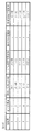
図3は、推測方位と距離の信頼度を決定する各要素について規定したものである。
前回信頼度は、図3に示すように、前回のマップマッチングにおいて算出した推測方位の信頼度と、推測距離の信頼度をそのまま使用する。
これは、推測航法により求めた推測方位の信頼度は、ジャイロの故障を除き、急激に変化する場合はないと考えられるため、前回の信頼度をそのまま使用するものである。
FIG. 3 defines the elements that determine the estimated orientation and the reliability of the distance.
As shown in FIG. 3, the reliability of the estimated orientation calculated in the previous map matching and the reliability of the estimated distance are used as the previous reliability.
This is because the reliability of the estimated azimuth obtained by dead reckoning does not change rapidly except for the gyro failure, and the previous reliability is used as it is.
通常、ナビゲーション装置の左右が水平に取り付けられていれば、ジャイロセンサの左右感度はほぼ等しくなる。このため、ジャイロセンサの左右感度がずれている場合、左右感度の学習が間違っている可能性が高く、方位変化時に誤差がでると考えられる。
そこで、想定累積方位誤差は、所定区間(例えば、10m)を走行する間の方位変化に対して、方位誤差は累積して大きくなると考えられるため、累積方位誤差(度)が大きくなるほど信頼度は小さくなるように規定されている。
本実施形態では、方位誤差率として、左右感度差1°に対して、0.1%の割合で設定されている。従って、ジャイロセンサの左右感度差α°に0.001を乗じた値を所定区間の走行毎に累積する。
なお、左右感度差は、次に説明するジャイロ感度学習による補正後の左右感度差が使用される。
Usually, if the left and right sides of the navigation device are mounted horizontally, the left and right sensitivities of the gyro sensor are substantially equal. For this reason, when the left and right sensitivity of the gyro sensor is shifted, there is a high possibility that learning of the left and right sensitivity is incorrect, and it is considered that an error occurs when the direction changes.
Therefore, since the assumed cumulative azimuth error is considered to increase cumulatively with respect to the azimuth change during traveling in a predetermined section (for example, 10 m), the reliability increases as the cumulative azimuth error (degree) increases. It is specified to be smaller.
In the present embodiment, the azimuth error rate is set at a rate of 0.1% with respect to a left / right sensitivity difference of 1 °. Accordingly, a value obtained by multiplying the gyro sensor left-right sensitivity difference α ° by 0.001 is accumulated for each traveling of the predetermined section.
Note that the left-right sensitivity difference after correction by gyro sensitivity learning described below is used as the left-right sensitivity difference.
ジャイロ感度学習状態は、ジャイロセンサに対する感度学習の回数を表し、感度学習の回数が少ない場合には推測方位の精度が低く、学習回数が多い場合に精度が高いと考えられるため、学習回数の増加に応じて信頼度が高くなるように設定されてる。
なお、本実施形態におけるジャイロセンサの感度学習の回数は、左折に対する学習と、右折に対する学習のセットで1回カウントされる。
The gyro sensitivity learning state represents the number of times of sensitivity learning for the gyro sensor, and the accuracy of the guess direction is low when the number of sensitivity learning is small, and the accuracy is high when the number of learning is large. The reliability is set to be higher depending on
Note that the number of times of gyro sensor sensitivity learning in this embodiment is counted once for a set of learning for a left turn and learning for a right turn.
ここで、ジャイロの感度学習は、右折及び左折に対するジャイロセンサの感度を補正するもので、周知の各種方法により行われる。
例えば、右左折時においてジャイロセンサから求めた角度を、GPS測位による走行軌跡から求めた角度によって補正する。この学習は、GPS測位による精度が低い場合には補正により感度が悪化する可能性があるので、GPS測位の精度が高い場合における右左折時に行われる。
例えば、GPS速度が30km/h以上であり、DOPから求まる誤差円の直径が100m以内であることを学習開始条件として、学習が行われる。なお、学習開始条件としては、さらに、車両現在位置の周辺に所定以上の高度のビルが存在しないことを条件に追加するようにしてもよい。
Here, the gyro sensitivity learning corrects the sensitivity of the gyro sensor for right and left turns, and is performed by various known methods.
For example, the angle obtained from the gyro sensor at the time of turning left or right is corrected by the angle obtained from the traveling locus by GPS positioning. This learning is performed at the time of a right or left turn when the accuracy of GPS positioning is high because the sensitivity may deteriorate due to correction when the accuracy by GPS positioning is low.
For example, the learning is performed with the GPS speed being 30 km / h or more and the diameter of the error circle determined from the DOP being within 100 m as a learning start condition. In addition, as a learning start condition, you may make it add on condition that the building more than predetermined | prescribed or higher does not exist in the periphery of the vehicle present position further.
推測方位信頼度は、推測距離の信頼度を求めるために使用するもので、推測方位の信頼度が高ければ、推測距離の精度も高いと考えられるので推測方位信頼度(各要素から求めた最終値)をそのまま使用する。 The estimated azimuth reliability is used to determine the reliability of the estimated distance. If the reliability of the estimated azimuth is high, the accuracy of the estimated distance is considered high. Value) is used as is.
距離係数学習状態は、距離に対する学習回数を示し、学習回数が多ければ、距離係数の精度は高い(推測距離の精度が高い)と考えられるので、推測距離の信頼度も高く規定されている。
ここで距離に対する学習も、ジャイロの感度学習と同様に、周知の各種方法を使用することができる。
例えば、GPS測位により算出した車両の移動距離を基準とし、車両の走行距離を計測する距離センサで出力される距離パルスの回数を計数することで距離パルス1回に対する移動距離を算出した回数を学習回数とする。距離パルス1回当たりの移動距離は、各学習で求めた移動距離の分布から最も多い値に基づいて統計的に決定する。
なお、距離に対する学習も、ジャイロの学習と同様にGPSの精度が高い場合に行われ、車両が所定距離だけ移動する間で学習開始条件を満たしている必要がある。
The distance coefficient learning state indicates the number of learning with respect to the distance. If the number of learning is large, the accuracy of the distance coefficient is considered to be high (the accuracy of the estimation distance is high).
Here, for the distance learning, various well-known methods can be used as in the gyro sensitivity learning.
For example, learning the number of times the distance traveled was calculated for one distance pulse by counting the number of distance pulses output by a distance sensor that measures the distance traveled by the vehicle based on the distance traveled by the GPS positioning Number of times. The movement distance per distance pulse is statistically determined based on the most frequent value from the distribution of movement distances obtained in each learning.
Note that distance learning is also performed when GPS accuracy is high, similar to gyro learning, and the learning start condition must be satisfied while the vehicle moves a predetermined distance.
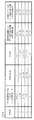
図4は、GPS方位と距離の信頼度を決定する各要素について規定したものである。
GPS・推測軌跡方位一致度は、GPSによる軌跡の形状と推測軌跡の形状の一致度を判定するものである。推測方位の変化量とGPS方位の変化量が近ければ(差が小さければ)、GPS方位の精度は高いと考えられることから、図4に示すように、両方位の一致度が高いほど、GPS方位の信頼度が高く規定されている。
FIG. 4 defines each element that determines the reliability of the GPS azimuth and distance.
The GPS / estimated trajectory azimuth coincidence determines the degree of coincidence between the shape of the trajectory by GPS and the shape of the estimated trajectory. If the estimated azimuth change amount and the GPS azimuth change amount are close (if the difference is small), it is considered that the accuracy of the GPS azimuth is high. Therefore, as shown in FIG. High reliability of orientation is specified.
ここで、GPS・推測軌跡方位一致度は次のようにして算出する。
(a)GPS信頼度算出位置(最新GPS測位点)を基点とする。
同様に推測軌跡は、GPSの基点と同mの推測軌跡位置(同期した位置)を基点とする。
Here, the GPS / estimated locus orientation coincidence is calculated as follows.
(A) The GPS reliability calculation position (latest GPS positioning point) is used as a base point.
Similarly, the estimated trajectory is based on the estimated trajectory position (synchronized position) of the same m as the GPS base point.
(b)基点から、測位点間隔でGPS測位点を最大20点取得し、基点方位からの方位変化量を各測位点毎に取得する。この時、GPSの連続性(測位間隔)を5秒以内とする(2、3秒非測位になっても処理が動く)。
同様に、推測軌跡も基点方位からの方位変化量を、各測位点に対応する点毎に取得する(推測軌跡座標はGPS測位m位置と同期をとること)。
(B) From the base point, a maximum of 20 GPS positioning points are acquired at the positioning point interval, and the azimuth change amount from the base point direction is acquired for each positioning point. At this time, the continuity of GPS (positioning interval) is set to within 5 seconds (the process moves even if the positioning is not performed for a few seconds).
Similarly, the estimated trajectory also obtains an azimuth change amount from the base direction for each point corresponding to each positioning point (the estimated trajectory coordinate is synchronized with the GPS positioning m position).
(c)取得したGPSと推測軌跡の各方位変化量に対して、対応する測位点間の差分を算出し、その和をとり平均値を算出する(相関値)。この相関値が図4平均方位差(°)となる。
なお、取得するGPS方位は、GPS方位信頼度が2以上のもののみとする。
(C) For each direction change amount of the acquired GPS and the estimated trajectory, a difference between corresponding positioning points is calculated, and the sum is calculated to calculate an average value (correlation value). This correlation value is the average orientation difference (°) in FIG.
Note that the GPS orientation to be acquired is only those having a GPS orientation reliability of 2 or more.
GPS速度が速ければ、GPS方位の精度は高くなると考えられるので、図4に示すように、信頼度も高く規定されている。 If the GPS speed is high, the accuracy of the GPS azimuth is considered to be high. Therefore, as shown in FIG. 4, the reliability is also defined high.
DOP(Dilution Of Precision)は、GPS衛星の配置から計算される測位精度を示す値(精度低下率)で、DOPが小さければGPS距離、GPS方位も比較的高いと考えられるので、図4に示すように、信頼度も高く規定されている。なお、DOP値は1.0が最もよい値である。
DOPには、幾何学的精度低下率HDOP、水平精度低下率PDOP、位置精度低下率RDOP等があり、本実施形態ではHDOPを使用するが、他を使用し、また、他を併用してもよい。
DOPは、GPS受信装置14で算出される。
DOP (Division Of Precision) is a value (decrease rate of accuracy) indicating the positioning accuracy calculated from the arrangement of GPS satellites. If DOP is small, the GPS distance and GPS azimuth are considered to be relatively high. As described above, the reliability is also set high. Note that 1.0 is the best DOP value.
The DOP includes a geometric accuracy decrease rate HDOP, a horizontal accuracy decrease rate PDOP, a position accuracy decrease rate RDOP, and the like. In this embodiment, HDOP is used, but other may be used and other may be used in combination. Good.
The DOP is calculated by the
座標間距離によるGPS・推測軌跡位置一致度は、図4で規定される。推測軌跡との距離の一致度が高ければ、GPS距離の精度も高いと考えられるので、座標間距離によるGPS・推測軌跡位置一致度の信頼度も高く規定されてる。 The GPS / estimated trajectory position coincidence according to the inter-coordinate distance is defined in FIG. If the degree of coincidence with the estimated trajectory is high, it is considered that the accuracy of the GPS distance is high. Therefore, the reliability of the GPS / estimated trajectory position coincidence according to the inter-coordinate distance is also defined to be high.
この座標間距離によるGPS・推測軌跡位置一致度は、次のようにして算出する。
(a)GPS信頼度算出位置(最新GPS測位点)を基点とする。
同様に推測軌跡は、GPSの基点に対応して測定される推測軌跡位置を基点とする。
(b)GPS基点位置から10m以上間の間隔でGPS測位点を10点取得し、基点からの座標間距離を算出する。
同様に、推測軌跡について、推測軌跡位置の基点から、GPSの各測位点に対応する各位置までの座標間距離を算出する。
(c)(b)で算出した、対応するGPS位置(測位点)と推測位置までの両座標間距離の差分を、各測位点毎に算出し、2乗の和をとり平均値を算出する(相関値)。
この相関値から信頼度を決定する。
The GPS / estimated locus position coincidence based on the inter-coordinate distance is calculated as follows.
(A) The GPS reliability calculation position (latest GPS positioning point) is used as a base point.
Similarly, the estimated trajectory is based on the estimated trajectory position measured corresponding to the GPS base point.
(B) Ten GPS positioning points are acquired at intervals of 10 m or more from the GPS base point position, and the inter-coordinate distance from the base point is calculated.
Similarly, for the estimated trajectory, an inter-coordinate distance from the base point of the estimated trajectory position to each position corresponding to each GPS positioning point is calculated.
(C) The difference between the coordinates between the corresponding GPS position (positioning point) and the estimated position calculated in (b) is calculated for each positioning point, and the sum of the squares is calculated to calculate the average value. (Correlation value).
The reliability is determined from this correlation value.
座標間方位によるGPS・推測軌跡位置一致度は、図4で規定されている。すなわち、推測軌跡との座標間の方位の一致度が高ければ、GPS方位の精度も高いと考えられるので、座標間方位によるGPS・推測軌跡位置一致度の信頼度も高く規定されてる。 The GPS / estimated locus position coincidence according to the inter-coordinate azimuth is defined in FIG. That is, if the degree of coincidence of the azimuth between coordinates with the estimated trajectory is high, it is considered that the accuracy of the GPS azimuth is high.
この座標間方位によるGPS・推測軌跡位置一致度は、次のようにして算出する。
(a)GPS信頼度算出位置(最新GPS測位点)から、10m以上の間隔でGPS測位点を最大10点取得し、隣どうしの2点間の座標から、当該2点間に対する方位を算出する。なお、本実施形態では、比較する点間の間隔が小さいと、少しのずれでも方位が大きく成ってしまうため10m以上の間隔に設定している。
同様に、推測軌跡についても、GPS測位点に対応する各位置に対し、隣どうしの2点間の座標から、当該2点間に対する方位を算出する。
(b)GPS測位点に基づき算出した各方位に対して、隣同士の方位の差分を算出し、推測方位変化量を算出する。
同様に、推測軌跡についても、各点に基づき算出した各方位に対して、隣同士の方位の差分を算出し、方位変化量を算出する。
The GPS / estimated trajectory position coincidence based on the inter-coordinate azimuth is calculated as follows.
(A) A maximum of 10 GPS positioning points are acquired at intervals of 10 m or more from the GPS reliability calculation position (latest GPS positioning point), and an orientation with respect to the two points is calculated from coordinates between two adjacent points. . In this embodiment, if the distance between the points to be compared is small, the azimuth becomes large even with a slight deviation, so the distance is set to 10 m or more.
Similarly, for the estimated trajectory, for each position corresponding to the GPS positioning point, the azimuth between the two points is calculated from the coordinates between the two adjacent points.
(B) For each azimuth calculated based on the GPS positioning point, a difference between adjacent azimuths is calculated, and an estimated azimuth change amount is calculated.
Similarly, for the estimated trajectory, the difference between the adjacent azimuths is calculated for each azimuth calculated based on each point, and the azimuth change amount is calculated.
(c)(b)で算出した、対応するGPSの方位変化量と推測方位変化量の差分を、各点毎に算出し、2乗の和をとり平均値を算出する(相関値)。
この相関値から信頼度を決定する。
(C) The difference between the corresponding GPS azimuth change and estimated azimuth change calculated in (b) is calculated for each point, and the sum of the squares is calculated to calculate the average value (correlation value).
The reliability is determined from this correlation value.
以上により各要素毎に信頼度を求め、最終的な推測方位と距離、GPS方位と距離の各信頼度は、要素毎の信頼度の平均値として算出する。
例えば、GPS距離の信頼度は、DOPによる信頼度が4、座標間距離によるGPS・推測軌跡位置一致度による信頼度が3、座標間方位によるGPS・推測軌跡位置一致度による信頼度が3であれば、これら3要素の信頼度の平均値が3.33となる。
図2(a)で示した想定距離誤差(想定最大誤差e)を求める場合には、求めた平均値3.33を四捨五入した値3を信頼度とする。これにより信頼度3に対応する想定方位誤差は10度以内となる。
なお、より精度を高めるため、求めた平均値を五捨六入、六捨七入、…としても良く、また小数点以下を切り捨てするようにしてもよい。
The reliability is obtained for each element as described above, and the final estimated azimuth and distance and the reliability of the GPS azimuth and distance are calculated as an average value of the reliability for each element.
For example, the reliability of the GPS distance is 4 by the DOP, 3 by the GPS / estimated trajectory position coincidence by the inter-coordinate distance, and 3 by the GPS / estimated trajectory position coincidence by the inter-coordinate direction. If there is, the average reliability of these three elements is 3.33.
When the assumed distance error (assumed maximum error e) shown in FIG. 2A is obtained, the
In order to improve the accuracy, the obtained average value may be rounded to the nearest whole number, rounded to the nearest whole number, or may be rounded down.
また、各要素の信頼度に対して重み付けをするようにしてもよい。
この場合、重み付けとしては、前回信頼度の重み付けを他の要素よりも高くする。
例えば、前回信頼度を1.5倍、想定累積方位誤差の信頼度を0.8倍、ジャイロ感度学習状態の信頼度を0.7倍する。
更に、各要素毎に算出した信頼度に基づき、ファジィ制御により最終的な信頼度を決定するようにしてもよい。
In addition, the reliability of each element may be weighted.
In this case, as the weighting, the weighting of the previous reliability is set higher than other elements.
For example, the previous reliability is 1.5 times, the reliability of the assumed cumulative azimuth error is 0.8 times, and the reliability of the gyro sensitivity learning state is 0.7 times.
Furthermore, the final reliability may be determined by fuzzy control based on the reliability calculated for each element.
このように構成されたナビゲーション装置では、次のようにして経路案内が行われる。
ナビゲーション装置は、現在位置検出装置10で現在位置を検出し、情報記憶装置50の地図データファイル51から現在位置周辺の地図情報を読み込みディスプレイ42に表示する。
そして、入力装置41から目的地が入力されると、情報処理制御装置20は、現在位置から目的地に至る走行経路の候補を複数探索(演算)し、ディスプレイ42に表示した地図上に表示し、運転者がいずれかの走行経路を選択すると、選択した走行経路をRAM24に格納することで、走行経路を取得する(走行経路取得手段)。
In the navigation device configured as described above, route guidance is performed as follows.
The navigation device detects the current position by the current
When the destination is input from the
なお、情報処理制御装置20は、情報処理センタに車両現在位置(又は入力された出発地)と目的地を送信し、情報処理センタで探索された目的地までの走行経路を受信することにより走行経路を取得するようにしてもよい。この場合、目的地や走行経路の通信は通信インターフェイス25を介して、無線通信により行う。
また、自宅等のパーソナルコンピュータ等の情報処理装置を使用して、出発地から目的地までの走行経路を探索し、USBメモリ等の記憶媒体に格納し、該記憶媒体読取り装置を介して取得するようにしてもよい。この場合の記憶媒体読取装置は伝送路45を介して情報処理制御装置20に接続される。
The information
In addition, a travel route from the departure place to the destination is searched using an information processing device such as a personal computer at home, etc., stored in a storage medium such as a USB memory, and obtained via the storage medium reader. You may do it. The storage medium reading device in this case is connected to the information
車両が走行すると、現在位置検出装置10によって検出された現在位置を追跡することにより、経路案内を行う。
経路案内は、探索した走行経路に対応する道路データと現在位置検出装置10で検出される現在位置とのマップマッチングにより地図上の車両位置を特定し、車両現在位置周辺の地図をディスプレイ42に表示し、探索した走行経路を地図上に表示すると共に、車両の現在位置を示す現在位置マークを地図上に表示する。
また、探索した走行経路と現在位置との関係から、案内の必要性、すなわち直進が所定距離以上続く場合、所定の進路変更地点等の走行経路の案内、及び方面案内が必要か否か等について判断し、必要である場合にはディスプレイ42の表示及び音声による案内を実行する。
When the vehicle travels, route guidance is performed by tracking the current position detected by the current
In the route guidance, the vehicle position on the map is specified by map matching between the road data corresponding to the searched driving route and the current position detected by the current
Also, based on the relationship between the searched travel route and the current position, the necessity of guidance, that is, whether or not guidance for a travel route such as a predetermined route change point and direction guidance is necessary when straight traveling continues for a predetermined distance or more, etc. Judgment is made, and if necessary, display on the
次に、このように構成されたナビゲーション装置による、マップマッチング処理について説明する。
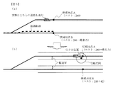
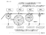
図5は、GPS信頼度と道路幅員を考慮した場合と考慮しない場合(従来)の、分岐点通過以降のマップマッチング処理による現在位置の特定(最有力方補の決定)状態について表したものである。
従来のマップマッチングでは、図5(a)に示すように、実際には図面上側の道路を走行している場合でも、分岐点通過後に一度下側の道路に誤マッチングされてしまうと、マッチングしているリンク(道路)上に現在位置や走行軌跡が修正されてしまう。このため、通常コスト計算では、実際の走行道路の方向等が大きく変化するまで、誤マッチング状態から復帰しにくい状態となる。
Next, map matching processing by the navigation device configured as described above will be described.
FIG. 5 shows the current position specification (determination of the most prominent method) by map matching processing after passing through a branch point when GPS reliability and road width are considered (conventional). is there.
In the conventional map matching, as shown in FIG. 5 (a), even when actually driving on the road on the upper side of the drawing, if it is erroneously matched with the lower road once after passing the branch point, the matching is performed. The current position and the traveling locus are corrected on the link (road). For this reason, in the normal cost calculation, it becomes difficult to return from the incorrect matching state until the direction of the actual traveling road changes greatly.
これに対して本実施形態によるマップマッチング処理では、狭角分岐通過後に誤マッチングがあったとしても、図5(b)に示すように、誤マッチングした道路上の候補地点Bは、GPS位置までの距離dが幅員W以下ではなく、更に、候補地点Bから幅員W離れた点が信頼度円内に存在もしていないため、大きなGPSコストが分岐点通過後累積的に通常コストに加算される。
一方、実際に走行している側(図面上側)の道路上に設定された候補地点Aに対しては、GPS位置までの距離dが幅員W以下であるので、GPSコストが加算されない。
On the other hand, in the map matching processing according to the present embodiment, even if there is an erroneous matching after passing through a narrow-angle branch, as shown in FIG. The distance d is not less than or equal to the width W, and further, there is no point within the reliability circle that is separated from the candidate point B by the width W, so a large GPS cost is cumulatively added to the normal cost after passing through the branch point. .
On the other hand, for the candidate point A set on the road on the actually running side (upper side in the drawing), the distance d to the GPS position is equal to or less than the width W, so the GPS cost is not added.
このように分岐点通過後、各回のコスト計算による通常コストに、GPSコストが累積的に加算されるため、図5(b)に示されるように、最有力候補地点が候補地点Bから候補地点Aに入れ替わり、分岐後の両道路が並行している場合であっても、正しい道路へマッチングさせることができる。 Thus, after passing through the branch point, the GPS cost is cumulatively added to the normal cost by each cost calculation, so that the most probable candidate point is changed from the candidate point B to the candidate point as shown in FIG. Even if the road is switched to A and both roads after branching are parallel, matching to the correct road can be performed.
また、GPSコストが累積的に加算されるので、正しい道路にマッチングしている場合に、通常コストにGPSコストを加算したコストは、一時的にGPS位置が大きくずれてたとしても急変(大きく変化)しないため、誤マッチングやハンチング(マッチング対象の変更が繰り返されること)が発生しにくくなる。 In addition, since the GPS cost is cumulatively added, the cost obtained by adding the GPS cost to the normal cost is abruptly changed (significantly changed) even if the GPS position is temporarily significantly shifted when matching to the correct road. ), It is difficult for false matching and hunting (repetition of matching target changes) to occur.
また、本実施形態では、GPS位置までの距離dが幅員Wよりも大きい場合であっても、候補地点から道路の幅員Wだけ離れた幅員点wが信頼度円内に存在する場合には、当該候補地点が設定されている道路を走行している可能性が存在するので、幅員点wが信頼度円内に存在しない場合に比べて、加算するGPSコストを小さくしている。
このように各道路の幅員を考慮することでよりマップマッチングの精度を高めることができる。
Further, in the present embodiment, even when the distance d to the GPS position is larger than the width W, when the width point w separated from the candidate point by the width W of the road exists in the reliability circle, Since there is a possibility that the candidate point is traveling on the road where the candidate point is set, the GPS cost to be added is made smaller than in the case where the width point w does not exist in the reliability circle.
Thus, the accuracy of map matching can be improved by considering the width of each road.
さらに、本実施形態では、GPSのDOPに基づく誤差円よりも、より精度の高い信頼度円、すなわち、誤差円よりも半径が小さい円を用いているので、誤マッチングからの回復をより早く行うことができる。 Further, in the present embodiment, a reliability circle with higher accuracy than the error circle based on the GPS DOP, that is, a circle having a radius smaller than that of the error circle is used, so that recovery from erroneous matching is performed more quickly. be able to.
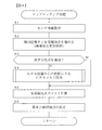
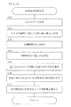
図6は、本実施形態によるマップマッチング処理の詳細を表したフローチャートである。
情報処理制御装置20は、現在位置検出装置10等で検出される各種センサ情報を取得する(ステップ1)。
そして、情報処理制御装置20は、次の手順により、推測航法による車両の推測位置Pと、各候補地の位置を進める(ステップ2)。
(i)前回の推測位置(P0とする)を基準とし、車両の移動距離と方位とに基づいて推測位置(P1とする)を求め、さらに、推測軌跡に基づき推測位置P1における推測方位(進行方向)を求める。
FIG. 6 is a flowchart showing details of the map matching process according to the present embodiment.
The information
Then, the information
(I) Using the previous estimated position (referred to as P0) as a reference, an estimated position (referred to as P1) is obtained based on the moving distance and direction of the vehicle, and further based on the estimated trajectory, the estimated direction (progress) Direction).
(ii)推測位置P1に対する各候補地点を特定する。
この候補地点は、推測位置P1から所定距離Lm以内に存在する道路に対して特定され、前回の推測位置P0でマッチングした各候補地点を、車両の移動距離分だけ道路に沿って移動させた地点を推測位置P1に対する候補地点とする。
なお、前回の候補地点P0を車両の移動距離分だけ道路に沿って移動させた結果、推測位置P1から所定距離Lm以内に存在しない場合には、その候補地点は候補対象外となる。
また、推測位置P1から所定距離の範囲内に、前回マップマッチング時の各候補地点が存在する道路と連続する道路で、分岐や交差点等による新たな道路が存在する場合には、各道路に対して、前回推測位置P0から車両移動距離分だけ移動させた地点を候補地点とする。
更に、推測位置P1から所定距離の範囲に、前回マップマッチング時の各候補地点が存在するいずれの道路とも連続しない新たな道路が存在する場合には、推測位置P1から当該道路に引いた垂線と交わる点を新たな候補地点として設定する。
(Ii) Identify each candidate point for the estimated position P1.
This candidate point is specified for a road existing within a predetermined distance Lm from the estimated position P1, and each candidate point matched at the previous estimated position P0 is moved along the road by the moving distance of the vehicle. Is a candidate point for the estimated position P1.
In addition, when the previous candidate point P0 is moved along the road by the moving distance of the vehicle, if the candidate point does not exist within the predetermined distance Lm from the estimated position P1, the candidate point is not a candidate target.
In addition, if there are new roads such as branches or intersections within the range of a predetermined distance from the estimated position P1 and continuous with the road where each candidate point at the previous map matching exists, Thus, a point moved from the previously estimated position P0 by the vehicle moving distance is set as a candidate point.
Furthermore, when there is a new road that is not continuous with any road where each candidate point at the time of previous map matching exists within a predetermined distance from the estimated position P1, a perpendicular line drawn from the estimated position P1 to the road The intersecting point is set as a new candidate point.
次に情報処理制御装置20は、車両が狭角分岐点を通過しているか否かを判断する(ステップ3)。この狭角分岐点を通過してから所定距離の間は本実施形態による幅員WとGPS信頼度を考慮したマップマッチングを行うので、分岐点通過後所定距離(例えば、1km)以内は通過と判断する。
分岐が狭角分岐か否かについては、道路データファイル54の分岐する道路が狭角分岐である場合を示す狭角分岐情報に基づき判断する。
Next, the information
Whether or not the branch is a narrow-angle branch is determined based on narrow-angle branch information indicating that the road on which the road data file 54 branches is a narrow-angle branch.
狭角分岐を通過していない場合(ステップ3;N)、情報処理制御装置20は、ステップ5に移行し、ステップ2で移動した各候補地点に対して通常のコスト計算(後述する)を行う(ステップ5)。
一方、狭角分岐を通過している場合(ステップ3;Y)、情報処理制御装置20は、GPS位置からの距離によるGPSコストを取得する(ステップ4)。
When the narrow angle branch is not passed (
On the other hand, when passing through the narrow-angle branch (
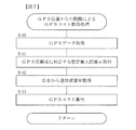
図7は、GPS位置からの距離によるGPSコスト取得処理を表したフローチャートである。
情報処理制御装置20は、GPSデータを取得し(ステップ40)、GPS信頼度に対応する想定最大誤差eを取得する(ステップ41)。
すなわち、情報処理制御装置20は、図4で説明したように、GPS距離の各要素(DOP、座標間距離によるGPS・推測軌跡位置一致度、座標間方位によるGPS・推測軌跡位置一致度)に基づく各信頼度を算出し、これらの平均値を四捨五入した信頼度を求め、この信頼度に対応する想定最大誤差e(図2(a)の信頼度に対応した距離)を取得する。
FIG. 7 is a flowchart showing GPS cost acquisition processing based on the distance from the GPS position.
The information
That is, as described with reference to FIG. 4, the information
また情報処理制御装置20は、DB(道路データファイル54)から、各候補地点が設定されている道路の幅員Wを取得する(ステップ42)。
そして、GPS位置からの距離dと幅員Wに基づくGPSコストを各候補地点に対して算出する(ステップ43)。
Further, the information
Then, a GPS cost based on the distance d from the GPS position and the width W is calculated for each candidate point (step 43).
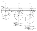
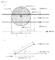
図8は、候補地点に対するGPS位置Gと幅員Wの関係について表したものである。
図8において、信頼度円は、GPS位置Gを中心とし、ステップ41で取得した想定最大誤差e(m)を半径とする円である。幅員円は、候補地点を中心とし、幅員W(m)を半径とする円である。なお、GPS位置Gと候補点を結ぶ線分と幅員円との交点が幅員点wである。
また、GPS位置Gと候補地点との距離をd、図8(b)に示すように、GPS位置Gと幅員点wとの距離をL1(=d−W)、幅員点wから信頼度円までの距離をL2(=L1−e=d−W−e)とする。
FIG. 8 shows the relationship between the GPS position G and the width W with respect to the candidate point.
In FIG. 8, the reliability circle is a circle centered on the GPS position G and having the assumed maximum error e (m) acquired in
Further, the distance between the GPS position G and the candidate point is d, and the distance between the GPS position G and the width point w is L1 (= d−W), as shown in FIG. Is the distance L2 (= L1-e = dWe).
そして、図8(a)〜(c)に示す、GPS位置G、候補地点A、幅員Wの各関係に応じて、次のようにGPSコストを決定する。
図8(a)は、GPS位置Gと候補地点A1との距離dが、幅員Wより小さい場合(d≦W)である。すなわち、幅員円の中にGPS位置Gが存在している場合である。
この場合の候補地点A1近傍に車両が存在する可能性が高いので、GPSコストは0である。すなわち、候補地点A1にはGPSコストを加算しない。
And according to each relationship of GPS position G, candidate point A, and width W shown to Fig.8 (a)-(c), GPS cost is determined as follows.
FIG. 8A shows a case where the distance d between the GPS position G and the candidate point A1 is smaller than the width W (d ≦ W). That is, this is a case where the GPS position G exists in the width circle.
In this case, the GPS cost is 0 because there is a high possibility that a vehicle is present near the candidate point A1. That is, the GPS cost is not added to the candidate point A1.
一方、図8(b)は、距離d>幅員Wで、かつ、距離d≦幅員W+想定最大誤差eの場合(L1−e≦0)である。すなわち、幅員円の中にGPS位置Gが存在しないが、幅員点wが信頼度円内に存在する場合であり、
この場合、候補地点A2に対して、GPS位置Gと幅員点wとの距離L1に比例したGPSコストk1を加算する。ただし、幅員Wの範囲で車両が存在している可能性が残されているので、比例常数を小さくする。
On the other hand, FIG. 8B shows the case where distance d> width W and distance d ≦ width W + assumed maximum error e (L1−e ≦ 0). That is, the GPS position G does not exist in the width circle, but the width point w exists in the reliability circle,
In this case, a GPS cost k1 proportional to the distance L1 between the GPS position G and the width point w is added to the candidate point A2. However, since the possibility that the vehicle exists in the range of the width W remains, the proportional constant is reduced.
具体的には、次の数式(1)によりGPSコストk1を算出する。
GPSコストk1=距離L1×比例定数H1…(1)
ここで、比例定数H1=Kd/想定最大誤差eである。
Kdは信頼度円境界コスト(固定値)で、距離L1=想定最大誤差eとした場合のGPSコストk1(候補地点が信頼度円上に位置する場合のコストk1)である。
Specifically, the GPS cost k1 is calculated by the following formula (1).
GPS cost k1 = distance L1 × proportional constant H1 (1)
Here, the proportionality constant H1 = Kd / assumed maximum error e.
Kd is a reliability circle boundary cost (fixed value), which is a GPS cost k1 when the distance L1 = assumed maximum error e (cost k1 when the candidate point is located on the reliability circle).
また、図8(c)は、距離d>幅員Wで、かつ、距離d>幅員W+想定最大誤差eの場合(L2=L1−e>0)である。すなわち、幅員円の中にGPS位置Gが存在せず、且つ、幅員点wが信頼度円内に存在もしていない場合である。
この場合、候補地点A3に対して、幅員点wから信頼度円までの距離L2に比例したGPSコストk2を加算する。ただし、幅員点wも信頼度円内に存在しないほどにGPS位置Gが離れているので、比例定数H2を図8(b)の場合の比例定数H1よりも大きくする。
FIG. 8C shows the case where distance d> width W and distance d> width W + assumed maximum error e (L2 = L1-e> 0). That is, the GPS position G does not exist in the width circle, and the width point w does not exist in the reliability circle.
In this case, a GPS cost k2 proportional to the distance L2 from the width point w to the reliability circle is added to the candidate point A3. However, since the GPS position G is so far away that the width point w does not exist in the reliability circle, the proportionality constant H2 is set larger than the proportionality constant H1 in the case of FIG.
具体的には、次の数式(2)によりGPSコストk2を算出する。
GPSコストk2=L2×比例定数H2+信頼度円境界コストKd …(2)
ここで、比例定数H2>比例定数H1である。
なお、GPSコストk2は、上限が設けられており、L2が上限距離Lm以上である場合には、L2=Lmとして式(2)によりGPSコストk2が算出される。
Specifically, the GPS cost k2 is calculated by the following formula (2).
GPS cost k2 = L2 × proportional constant H2 + reliability circle boundary cost Kd (2)
Here, proportionality constant H2> proportionality constant H1.
Note that the GPS cost k2 has an upper limit, and when L2 is equal to or greater than the upper limit distance Lm, the GPS cost k2 is calculated by Equation (2) as L2 = Lm.
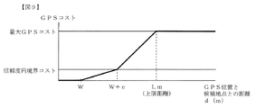
図9は、GPS位置と候補地点との距離dに対するGPSコストの値を表したものである。
この図9に示されるように、距離dが幅員WまではGPSコストが0で、幅員W〜幅員W+想定最大誤差eまでは距離L1に応じて小な傾きで増加するGPSコストk1、幅員W+想定最大誤差e〜上限距離Lmまでは距離L2に応じて大きな傾きで増加するGPSコストk2、上限距離Lmより大きい場合は一律最大のGPSコストとなる。
FIG. 9 shows the value of the GPS cost with respect to the distance d between the GPS position and the candidate point.
As shown in FIG. 9, the GPS cost is zero until the distance d is the width W, and the GPS cost k1 and the width W + that increase with a small inclination according to the distance L1 from the width W to the width W + the assumed maximum error e. From the assumed maximum error e to the upper limit distance Lm, the GPS cost k2 increases with a large slope according to the distance L2, and when it is larger than the upper limit distance Lm, the maximum uniform GPS cost is obtained.
なお、GPS受信後に車両が距離dr(m)だけ走行している場合には、数式(1)、(2)における幅員Wを換算した幅員W’に置き換えてGPSコストk1、k2を算出するようにしてもよい。
換算後の幅員W’は、実際の幅員Wと距離drから次の数式(3)により算出する。
W’=√(d×d+W×W) …(3)
When the vehicle travels a distance dr (m) after receiving the GPS, the GPS costs k1 and k2 are calculated by replacing the width W in the formulas (1) and (2) with the converted width W ′. It may be.
The converted width W ′ is calculated from the actual width W and the distance dr by the following formula (3).
W ′ = √ (d × d + W × W) (3)
以上のように、GPS位置と各候補地点との距離dと幅員Wの関係により各候補地点に対するGPSコストを算出(ステップ43)すると、情報処理制御装置20は、図6のメインルーチンにリターンし、各候補地点のコスト計算を行う(ステップ5)。
すなわち、情報処理制御装置20は、ステップ2で求めた車両の推測位置P1に対する各候補地のコストを計算する。
このコスト計算では、推測位置P1に対する通常コストを算出し、GPSコストが算出されている場合(ステップ4)にはGPSコストを加算する。
なお、各候補に対するGPSコストは、分岐点通過後所定距離までの間は各マップマッチングにおいて算出されたGPSコストが累積的に加算される。そのため、各候補地点に対して算出されたそれぞれの推測位置PにおけるGPSコスト(又は、累計したGPSコスト)はRAM24に保存されている。
As described above, when the GPS cost for each candidate point is calculated based on the relationship between the GPS position and the distance d between each candidate point and the width W (step 43), the information
That is, the information
In this cost calculation, the normal cost for the estimated position P1 is calculated, and when the GPS cost is calculated (step 4), the GPS cost is added.
In addition, the GPS cost calculated in each map matching is cumulatively added to the GPS cost for each candidate until a predetermined distance after passing through the branch point. Therefore, the GPS cost (or the accumulated GPS cost) at each estimated position P calculated for each candidate point is stored in the
通常コストの計算の考え方は次の通りである。
推測位置Pからの距離、方位差共に値が小さい候補地点ほど、最適な候補地点である可能性が高いと考えられる。
また、車速等の走行状態としては、高速(例えば、100km/h)で走行しているのであれば、高速道路を走行している可能性が高いと考えられる。
過去の状態は、近い過去に一般道(高速)を走行しているのであれば、一般道(高速)を走行している可能性が高いと考えられる。
過去の候補地点の状態としては、1つ前の候補地点における通常コストの1/2が使用される。
上記の各状態を点数化(距離差、方位差はその値を点数にする)し、その合計値を各候補地点に対する通常コストとして算出する。
The concept of normal cost calculation is as follows.
It is considered that a candidate point having a smaller value for both the distance from the estimated position P and the azimuth difference is more likely to be an optimal candidate point.
Moreover, if the vehicle is traveling at a high speed (for example, 100 km / h), it is highly likely that the vehicle is traveling on a highway.
If the past state is traveling on a general road (high speed) in the near past, it is highly likely that the vehicle is traveling on a general road (high speed).
As the state of the past candidate point, 1/2 of the normal cost at the previous candidate point is used.
Each of the above states is scored (the distance difference and the azimuth difference are scored), and the total value is calculated as the normal cost for each candidate point.
例えば、車両が時速100km/hで走行しているものとし、一般道上に設定された候補地点Xについて、距離差が5m、方位差が5度、走行状態が10(車速100km/hなので一般道を走行している可能性は低いため)、前回の通常コストが50であるとする。
この場合、候補地点Xの通常コスト合計は、5+5+10+(50×1/2)=45となる。
For example, it is assumed that the vehicle is traveling at a speed of 100 km / h, and the candidate point X set on the general road has a distance difference of 5 m, a heading difference of 5 degrees, and a traveling state of 10 (the vehicle speed is 100 km / h. Because the possibility of traveling is low), the previous normal cost is assumed to be 50.
In this case, the total normal cost of the candidate point X is 5 + 5 + 10 + (50 × 1/2) = 45.
一方、高速道路上に設定された候補地点Yについて、距離差が10m、方位差が3度、走行状態が0(車速100km/hなので高速道路を走行している可能性が高いため)、前回の通常コストが40であるとする。
この場合、候補地点Yの通常コスト合計は、10+3+0+(40×1/2)=33となる。
On the other hand, for candidate point Y set on the highway, the distance difference is 10 m, the heading difference is 3 degrees, and the driving state is 0 (because the vehicle speed is 100 km / h, it is highly likely that the vehicle is driving on the highway). It is assumed that the normal cost is 40.
In this case, the total normal cost of the candidate point Y is 10 + 3 + 0 + (40 × 1/2) = 33.
なお、上記の計算例は、通常コストについての考え方を示したものであり、実際の係数や加算の方法は、最適なものが採用される。 Note that the above calculation example shows the concept of the normal cost, and the optimum coefficient and the actual addition method are adopted.
情報処理制御装置20は、各候補地点に対するコスト(通常コスト+GPSコスト)を算出すると、コストが最も小さい候補地点を最有力の候補地点に決定すると共に、車両位置を最有力候補地点に決定し(ステップ6)、メインルーチンにリターンする。
When calculating the cost (normal cost + GPS cost) for each candidate point, the information
図10は、狭角分岐後の道路に対して正しくマッチングした場合の各候補地点に対するコスト(通常コスト+GPSコスト)と、最有力候補地点との関係を表したものである。
この図10に示されるように、本実施形態により次のような効果も得られる。
なお、図10に表示した各候補点に対するコストは、最初の数値がその地点での通常コストで、2つめ以降の数値が累積的に加算されるGPSコストである。
(a)GPSの信頼度に応じたGPS位置Gの誤差(想定最大誤差e)を考慮したコスト算出を行うことで、誤ったGPSコスト加算を最小限に抑えることができる。
(b)各地点の通常コストには、分岐点通過後の各候補地点におけるGPSコストを累積的に加算するため、一時的にGPS位置Gがずれても全体のコストは急変せず、誤マッチングやハンチングが発生しにくい。
(c)GPSの信頼度を考慮したコスト計算を行うことで、GPSの精度が高いときには想定最大誤差eが小さくなり、距離L2も大きくなることから、大きなGPSコストk2が加算され、誤マッチングから復帰しやすくなる。
FIG. 10 shows the relationship between the cost (normal cost + GPS cost) for each candidate point and the most probable candidate point when the road after narrow-angle branching is correctly matched.
As shown in FIG. 10, the following effects are also obtained by this embodiment.
The cost for each candidate point displayed in FIG. 10 is a GPS cost in which the first numerical value is the normal cost at that point and the second and subsequent numerical values are cumulatively added.
(A) By calculating the cost in consideration of the error of the GPS position G (assumed maximum error e) in accordance with the reliability of GPS, erroneous GPS cost addition can be minimized.
(B) Since the GPS cost at each candidate point after passing through the branch point is cumulatively added to the normal cost at each point, the overall cost does not change abruptly even if the GPS position G is temporarily shifted. And hunting is less likely to occur.
(C) By calculating the cost in consideration of the reliability of GPS, when the GPS accuracy is high, the assumed maximum error e becomes small and the distance L2 also becomes large. Therefore, a large GPS cost k2 is added, resulting in erroneous matching. It becomes easy to return.
以上、本実施形態の幅員WとGPS信頼度を考慮しコスト計算によるマップマッチングについて説明した。
この実施形態では、各候補地点の前後方向の位置精度がある程度高く、各候補地点が進行方向前後に大きくずれていない場合には、GPS位置からの距離に応じた異なるGPSコストが各候補点に累積的に加算されるため、誤マッチングから復帰し易くなるとともに、正しいマッチングから外れにくくなる。
しかし、各候補地点の前後方向の位置精度がある程度悪く、各候補地点が進行方向前後に大きくずれている場合には、全ての候補地点に対して上限値(最大GPSコスト)が加算されるため、GPSコストの加算による効果がない。
The map matching by the cost calculation has been described above in consideration of the width W and the GPS reliability of the present embodiment.
In this embodiment, when the position accuracy in the front-rear direction of each candidate point is high to some extent and each candidate point is not greatly deviated before and after the traveling direction, a different GPS cost corresponding to the distance from the GPS position is assigned to each candidate point. Since they are cumulatively added, it is easy to recover from erroneous matching and it is difficult to deviate from correct matching.
However, if the position accuracy in the front-rear direction of each candidate point is somewhat bad and the respective candidate points are greatly deviated before and after the traveling direction, the upper limit value (maximum GPS cost) is added to all candidate points. There is no effect by adding the GPS cost.
そこで、本実施形態の変形例として、各候補地点が進行方向前後に大きくずれている場合に、各候補地点の位置を補正しながら進めることで、徐々に前後方向の精度を高める場合について説明する。
図11は、各候補点の進行方向前後のずれに対応する補正についての概念説明図である。
図11(a)に示されるように、n本の道路上に設定された複数の候補地点A1〜Anが設定されているものとする。図の例では2本の道路に4つの候補地点A1〜A4が設定されている。この図のように、同一の道路に対して複数の候補地点が設定される場合がある。
例えば、推測位置Pから所定距離内に新たな道路が含まれることになり、その新たな道路が屈曲しているために、推測位置Pから2本の垂線が引ける場合や、候補地点が設定されている2本の道路が合流した場合などがある。
Therefore, as a modified example of the present embodiment, a case will be described in which the accuracy in the front-rear direction is gradually increased by correcting the position of each candidate point when each candidate point is largely displaced in the front-rear direction. .
FIG. 11 is a conceptual explanatory diagram of correction corresponding to the deviation of each candidate point before and after the traveling direction.
As shown in FIG. 11A, it is assumed that a plurality of candidate points A1 to An set on n roads are set. In the example of the figure, four candidate points A1 to A4 are set on two roads. As shown in this figure, a plurality of candidate points may be set for the same road.
For example, when a new road is included within a predetermined distance from the estimated position P and the new road is bent, two perpendicular lines can be drawn from the estimated position P, or candidate points are set. There are cases where two roads meet.
情報処理制御装置20は、これら候補地点群の重心点Qを各候補の座標値から算出する。すなわち、各候補地点の座標値の算術平均を重心点Qの座標値とする。
そして、重心点QがGPS位置から想定最大誤差eの範囲よりも前、又は後ろにある場合に、次の候補地点を移動するステップ2の処理において、移動量の補正を行う。
すなわち、情報処理制御装置20は、図11(b)に示すように、GPS位置に対する重心点Qの前後方向のずれR(推測軌跡の方位S方向のずれ)を次の数式(4)により算出し、ずれRが想定最大誤差eよりも大きい場合に補正を行う。
The information
Then, when the barycentric point Q is before or behind the range of the assumed maximum error e from the GPS position, the movement amount is corrected in the process of
That is, as shown in FIG. 11B, the information
R=d’×cos(θg−θt) …(4)
数式(4)において、d’は候補地点群の重心点QからGPS位置Gまでの距離(m)、θtは推測軌跡の方位(°)、θgは候補地点の重心からみたGPS位置Gの方位(°)である。
R = d ′ × cos (θg−θt) (4)
In Equation (4), d ′ is the distance (m) from the center of gravity Q of the candidate point group to the GPS position G, θt is the direction of the estimated locus (°), and θg is the direction of the GPS position G viewed from the center of gravity of the candidate point. (°).
補正は、候補更新のタイミングで、重心点QがGPS位置よりも後ろにある場合には通常よりも所定距離t(例えば、1m)だけ余分に進ませ、前にある場合には通常よりも所定距離tだけ遅らせることで、徐々に補正を実施する。 When the center of gravity Q is behind the GPS position at the timing of the candidate update, the correction is advanced by a predetermined distance t (for example, 1 m) more than usual, and when it is ahead, the correction is performed more than usual. The correction is gradually performed by delaying the distance t.
図12は、ステップ2において、本変形例の前後方向の補正処理を行う候補地点更新処理の内容を表したフローチャートである。
情報処理制御装置20は、GPSデータを取得し(ステップ21)、ステップ40で説明したと同様にしてGPS信頼度に対応する想定最大誤差eを取得する(ステップ22)。なお、本変形例のステップ22において取得した想定最大誤差eはRAM24に格納しておき、ステップ41ではRAM24から想定最大誤差eを読み出すことで取得する。
FIG. 12 is a flowchart showing the contents of the candidate point update process for performing the front-rear direction correction process of the present modification in
The information
次に情報処理制御装置20は、推測軌跡の方位Sを取得する(ステップ23)。すなわち、推測航法による前回の推測位置を基準とし、今回の推測位置から方位Sを取得する。
Next, the information
そして、情報処理制御装置20は、全候補地点群の重心点Qを算出する(ステップ24)。すなわち、前回の推測位置P0を基準とした車両の移動距離を、通常移動量として各候補地点をそれぞれの道路に沿って進行方向に移動させ、移動後の各候補地点座標から重心点Qを算出する。
Then, the information
情報処理制御装置20は、算出した重心点QとGPS位置の前後方向のずれRを算出し(ステップ25)、各候補地点の移動量を決定する(ステップ26)。
すなわち情報処理制御装置20は、ずれRが重心点Qよりも前方で、想定最大誤差eよりも大きい場合には、移動量=通常移動量−1(m)とする。
また、ずれRが想定最大誤差e以内であれば移動量=通常移動量(m)とする。
更に、ずれRが重心点Qよりも後方で、想定最大誤差eよりも大きい場合には、移動量=通常移動量+1(m)とする。
The information
That is, the information
If the deviation R is within the assumed maximum error e, the movement amount = the normal movement amount (m).
Further, when the deviation R is behind the center of gravity Q and larger than the assumed maximum error e, the movement amount = the normal movement amount + 1 (m).
情報処理制御装置20は、各候補地点の位置を、それぞれステップ26で決定した各移動量分だけ各々の道路上を進行歩行に移動させて(ステップ27)、メインルーチンにリターンする。
The information
なお、上記変形例の説明では、次の候補地点に対する重心点Qを求めて、ずれRが想定最大誤差e以内か否かを判断したが、前回の推測位置P0に対応する各候補地点(移動前の候補地点)の重心点Q’を求め、前回のGPS位置とのずれR’が想定最大誤差e以内か否かに基づいて、今回の候補点の移動の際に補正を行うようにしてもよい。 In the description of the modified example, the center of gravity Q for the next candidate point is obtained and it is determined whether or not the deviation R is within the assumed maximum error e. However, each candidate point (movement) corresponding to the previous estimated position P0 is determined. The gravity center point Q ′ of the previous candidate point) is obtained, and correction is performed during the movement of the current candidate point based on whether or not the deviation R ′ from the previous GPS position is within the assumed maximum error e. Also good.
以上、本発明のナビゲーション装置及びナビゲーション用プログラムにおける1実施形態及び変形例について説明したが、本発明は説明した実施形態に限定されるものではなく、各請求項に記載した範囲において更に各種の変形を行うことが可能である。
例えば、上述した実施形態及び変形例では、信頼度円の半径である想定最大誤差eをGPS信頼度に基づいて決定するようにしたが、GPSのDOPに基づく誤差円を使用するようにしてもよい。この場合の想定最大誤差は誤差円の半径を使用する。
As described above, the embodiment and the modification of the navigation device and the navigation program of the present invention have been described. However, the present invention is not limited to the described embodiment, and various modifications can be made within the scope described in each claim. Can be done.
For example, in the embodiment and the modification described above, the assumed maximum error e, which is the radius of the reliability circle, is determined based on the GPS reliability, but an error circle based on the GPS DOP may be used. Good. In this case, the assumed maximum error uses the radius of the error circle.
さらに、GPSコストを算出する場合に誤差円の半径を使用しなくてもよい。
この場合のGPSコストは、GPS位置と候補地点との距離dから、候補地点が設定されている道路の幅員Wを減算した値L1を求め、この値L1が大きいほど大きくなるようにGPSコストを算出する。
なお、この場合においても、距離d−幅員Wがマイナスとなる候補地点のGPSコストをゼロとするようにしてもよい。
Furthermore, the radius of the error circle need not be used when calculating the GPS cost.
In this case, the GPS cost is obtained by subtracting the width W of the road where the candidate point is set from the distance d between the GPS position and the candidate point, and the GPS cost is increased so that the value L1 increases. calculate.
Also in this case, the GPS cost of the candidate point where the distance d-width W is negative may be set to zero.
10 現在位置検出装置
20 情報処理制御装置
21 CPU
40 入出力装置
50 情報記憶装置
10 current
40 I / O device 50 Information storage device
Claims (6)
推測航法により車両の推測位置を取得する推測位置取得手段と、
GPSにより車両のGPS位置を取得するGPS位置取得手段と、
前記推測位置の周辺に存在する道路上に車両位置の候補地点を設定する候補地点設定手段と、
前記推測位置に対する候補地点の通常コストを前記各候補地点に対して算出する通常コスト算出手段と、
前記GPS位置と候補地点の距離dから、前記候補地点が設定されている道路の幅員Wを減算した値L1に応じた補正コストを前記各候補地点に対して算出する補正コスト算出手段と、
前記各候補地点に対する前記通常コストと前記補正コストとの合計コストから最有力候補地点を特定する、最有力候補地点特定手段と、
を具備したことを特徴とするナビゲーション装置。
A navigation device that identifies a most promising candidate point by cost calculation for a candidate point set on a road, and matches a vehicle position to the identified most promising candidate point,
Estimated position acquisition means for acquiring the estimated position of the vehicle by dead reckoning navigation;
GPS position acquisition means for acquiring the GPS position of the vehicle by GPS;
Candidate point setting means for setting a candidate point for the vehicle position on a road existing around the estimated position;
Normal cost calculating means for calculating the normal cost of the candidate point for the estimated position for each candidate point;
A correction cost calculating means for calculating a correction cost corresponding to a value L1 obtained by subtracting the width W of the road where the candidate point is set from the distance d between the GPS position and the candidate point;
A most probable candidate point identifying means for identifying the most probable candidate point from the total cost of the normal cost and the correction cost for each candidate point;
A navigation device comprising:
前記値L1から前記値前記想定最大誤差eを減算した値L2を算出する算出手段と、を備え、
前記補正コスト算出手段は、
前記値L2がマイナスである場合、前記値L1に第1比例定数を乗じた値を補正コストとし、
前記値L2がプラスである場合、前記値L2に前記第1比例定数よりも大きな第2比例定数を乗じた値と、前記想定最大誤差eに第1比例定数を乗じた値とを加算した値を補正コストとする、
ことを特徴とする請求項1に記載のナビゲーション装置。
An assumed maximum error calculating means for obtaining an assumed maximum error e indicating the distance of the error range with respect to the GPS position;
Calculating means for calculating a value L2 obtained by subtracting the assumed maximum error e from the value L1,
The correction cost calculation means includes
When the value L2 is negative, a value obtained by multiplying the value L1 by the first proportionality constant is used as a correction cost,
When the value L2 is positive, a value obtained by adding a value obtained by multiplying the value L2 by a second proportional constant larger than the first proportional constant and a value obtained by multiplying the assumed maximum error e by the first proportional constant Is the correction cost,
The navigation device according to claim 1.
The navigation device according to claim 1 or 2, wherein the correction cost calculation unit sets the correction cost to zero when the value L1 is negative.
The navigation apparatus according to claim 2, wherein the assumed maximum error e is a radius of an error circle based on the GPS DOP.
The assumed maximum error e is a distance according to the reliability calculated from DOP, the distance between the estimated position and the GPS position, and the difference between the azimuth by the locus of the estimated position and the azimuth by the locus of the GPS position. The navigation device according to claim 2.
推測航法により車両の推測位置を取得する推測位置取得機能と、
GPSにより車両のGPS位置を取得するGPS位置取得機能と、
前記推測位置の周辺に存在する道路上に車両位置の候補地点を設定する候補地点設定機能と、
前記推測位置に対する候補地点の通常コストを前記各候補地点に対して算出する通常コスト算出機能と、
前記GPS位置と候補地点の距離dから、前記候補地点が設定されている道路の幅員Wを減算した値L1に応じた補正コストを前記各候補地点に対して算出する補正コスト算出機能と、
前記各候補地点に対する前記通常コストと前記補正コストとの合計コストから最有力候補地点を特定する、最有力候補地点特定機能と、をコンピュータに実現させることを特徴とするナビゲーション用プログラム。 A navigation program for identifying the most promising candidate point by cost calculation for the candidate point set on the road, and matching the vehicle position to the identified most promising candidate point,
An estimated position acquisition function for acquiring an estimated position of the vehicle by dead reckoning navigation;
A GPS position acquisition function for acquiring the GPS position of the vehicle by GPS;
A candidate point setting function for setting a candidate point of the vehicle position on a road existing around the estimated position;
A normal cost calculation function for calculating the normal cost of the candidate point for the estimated position for each candidate point;
A correction cost calculation function for calculating a correction cost corresponding to a value L1 obtained by subtracting the width W of the road where the candidate point is set from the distance d between the GPS position and the candidate point;
A navigation program that causes a computer to realize a most probable candidate point identifying function that identifies a most probable candidate point from the total cost of the normal cost and the correction cost for each candidate point.
Priority Applications (4)
| Application Number | Priority Date | Filing Date | Title |
|---|---|---|---|
| JP2009043791A JP5142047B2 (en) | 2009-02-26 | 2009-02-26 | Navigation device and navigation program |
| CN201010121785.XA CN101819042B (en) | 2009-02-26 | 2010-02-11 | Navigation device and navigation program |
| US12/656,943 US8498813B2 (en) | 2009-02-26 | 2010-02-19 | Navigation device, method, and program |
| EP10154662.0A EP2224210B1 (en) | 2009-02-26 | 2010-02-25 | Navigation device and navigation method |
Applications Claiming Priority (1)
| Application Number | Priority Date | Filing Date | Title |
|---|---|---|---|
| JP2009043791A JP5142047B2 (en) | 2009-02-26 | 2009-02-26 | Navigation device and navigation program |
Publications (2)
| Publication Number | Publication Date |
|---|---|
| JP2010197279A true JP2010197279A (en) | 2010-09-09 |
| JP5142047B2 JP5142047B2 (en) | 2013-02-13 |
Family
ID=42289367
Family Applications (1)
| Application Number | Title | Priority Date | Filing Date |
|---|---|---|---|
| JP2009043791A Active JP5142047B2 (en) | 2009-02-26 | 2009-02-26 | Navigation device and navigation program |
Country Status (4)
| Country | Link |
|---|---|
| US (1) | US8498813B2 (en) |
| EP (1) | EP2224210B1 (en) |
| JP (1) | JP5142047B2 (en) |
| CN (1) | CN101819042B (en) |
Cited By (4)
| Publication number | Priority date | Publication date | Assignee | Title |
|---|---|---|---|---|
| WO2013065629A1 (en) * | 2011-11-04 | 2013-05-10 | 三菱重工業株式会社 | Movement path specification device and movement path specification method and program |
| JP2014163740A (en) * | 2013-02-22 | 2014-09-08 | Mitsubishi Heavy Ind Ltd | Passage detection system, passage detection method, passage detection device, program, and recording medium |
| JP2018009833A (en) * | 2016-07-12 | 2018-01-18 | 株式会社Soken | Vehicle self-localization device and vehicle self-localization method |
| JP2018040692A (en) * | 2016-09-07 | 2018-03-15 | 株式会社Soken | Self-vehicle position estimation device and self-vehicle position estimation method |
Families Citing this family (49)
| Publication number | Priority date | Publication date | Assignee | Title |
|---|---|---|---|---|
| US11482058B2 (en) | 2008-09-09 | 2022-10-25 | United Parcel Service Of America, Inc. | Systems and methods for utilizing telematics data to improve fleet management operations |
| US8416067B2 (en) | 2008-09-09 | 2013-04-09 | United Parcel Service Of America, Inc. | Systems and methods for utilizing telematics data to improve fleet management operations |
| US8645060B2 (en) * | 2010-09-07 | 2014-02-04 | Qualcomm Incorporated | Positioning network availability and reliability based routing |
| US9097539B2 (en) * | 2010-10-29 | 2015-08-04 | Toyota Jidosha Kabushiki Kaisha | Vehicle information processing device |
| US8447519B2 (en) * | 2010-11-10 | 2013-05-21 | GM Global Technology Operations LLC | Method of augmenting GPS or GPS/sensor vehicle positioning using additional in-vehicle vision sensors |
| JP5872764B2 (en) * | 2010-12-06 | 2016-03-01 | 富士通テン株式会社 | Image display system |
| US9129449B2 (en) | 2011-03-31 | 2015-09-08 | United Parcel Service Of America, Inc. | Calculating speed and travel times with travel delays |
| US9953468B2 (en) | 2011-03-31 | 2018-04-24 | United Parcel Service Of America, Inc. | Segmenting operational data |
| US9208626B2 (en) * | 2011-03-31 | 2015-12-08 | United Parcel Service Of America, Inc. | Systems and methods for segmenting operational data |
| US9823082B2 (en) * | 2011-08-24 | 2017-11-21 | Modular Mining Systems, Inc. | Driver guidance for guided maneuvering |
| JP5831308B2 (en) * | 2012-03-13 | 2015-12-09 | アイシン・エィ・ダブリュ株式会社 | Moving body position detection system, moving body position detection apparatus, moving body position detection method, and computer program |
| JP5928038B2 (en) * | 2012-03-19 | 2016-06-01 | カシオ計算機株式会社 | Information processing apparatus and program |
| US8898010B2 (en) | 2013-01-11 | 2014-11-25 | Here Global B.V. | Deviation detection in mobile transit systems |
| US10359290B2 (en) | 2013-03-22 | 2019-07-23 | Here Global B.V. | Method and apparatus for two dimensional edge-based map matching |
| JP6236954B2 (en) * | 2013-07-23 | 2017-11-29 | アイシン・エィ・ダブリュ株式会社 | Driving support system, method and program |
| JP6351235B2 (en) * | 2013-11-06 | 2018-07-04 | アルパイン株式会社 | Navigation system, computer program, and current position calculation method |
| US9805521B1 (en) | 2013-12-03 | 2017-10-31 | United Parcel Service Of America, Inc. | Systems and methods for assessing turns made by a vehicle |
| JP6250708B2 (en) * | 2014-01-14 | 2017-12-20 | 旭化成株式会社 | Traveling direction information output device, map matching device, traveling direction information output method, and program |
| US8942920B1 (en) | 2014-01-31 | 2015-01-27 | United Parcel Service Of America, Inc. | Concepts for determining the accuracy of map data |
| US9869557B2 (en) | 2014-01-31 | 2018-01-16 | United Parcel Service Of America, Inc. | Determining the accuracy of map data and providing reports for same |
| DE102014111126A1 (en) * | 2014-08-05 | 2016-02-11 | Valeo Schalter Und Sensoren Gmbh | Method for generating an environment map of an environmental area of a motor vehicle, driver assistance system and motor vehicle |
| JP6322523B2 (en) * | 2014-09-03 | 2018-05-09 | アイシン・エィ・ダブリュ株式会社 | Route search system, route search method and computer program |
| CN105526939B (en) * | 2014-09-29 | 2018-12-11 | 高德软件有限公司 | Road matching method and device |
| RU2610260C2 (en) | 2015-03-20 | 2017-02-08 | Общество С Ограниченной Ответственностью "Яндекс" | Method and server for identifying the geographic location of an electronic device |
| US20160334225A1 (en) | 2015-05-11 | 2016-11-17 | United Parcel Service Of America, Inc. | Determining street segment headings |
| US9684081B2 (en) * | 2015-09-16 | 2017-06-20 | Here Global B.V. | Method and apparatus for providing a location data error map |
| ES2946192T3 (en) | 2015-11-30 | 2023-07-13 | Signify Holding Bv | Distinguishing devices that have positions and directions |
| JP2019531560A (en) | 2016-07-05 | 2019-10-31 | ナウト, インコーポレイテッドNauto, Inc. | Automatic driver identification system and method |
| CN109416256B (en) * | 2016-07-05 | 2022-03-22 | 三菱电机株式会社 | Travel lane estimation system |
| US10037471B2 (en) | 2016-07-05 | 2018-07-31 | Nauto Global Limited | System and method for image analysis |
| CN106289282A (en) * | 2016-07-18 | 2017-01-04 | 北京方位捷讯科技有限公司 | A kind of indoor map pedestrian's track matching method |
| EP3497405B1 (en) * | 2016-08-09 | 2022-06-15 | Nauto, Inc. | System and method for precision localization and mapping |
| US9928432B1 (en) | 2016-09-14 | 2018-03-27 | Nauto Global Limited | Systems and methods for near-crash determination |
| US10733460B2 (en) | 2016-09-14 | 2020-08-04 | Nauto, Inc. | Systems and methods for safe route determination |
| JP6881464B2 (en) * | 2016-09-27 | 2021-06-02 | 日産自動車株式会社 | Self-position estimation method and self-position estimation device |
| CN107869996B (en) * | 2016-09-28 | 2019-04-30 | 腾讯科技(深圳)有限公司 | Method for processing navigation information and device |
| US10246014B2 (en) | 2016-11-07 | 2019-04-02 | Nauto, Inc. | System and method for driver distraction determination |
| US11584372B2 (en) * | 2016-12-28 | 2023-02-21 | Baidu Usa Llc | Method to dynamically adjusting speed control rates of autonomous vehicles |
| WO2018229550A1 (en) | 2017-06-16 | 2018-12-20 | Nauto Global Limited | System and method for adverse vehicle event determination |
| WO2018229548A2 (en) | 2017-06-16 | 2018-12-20 | Nauto Global Limited | System and method for contextualized vehicle operation determination |
| US11525688B2 (en) | 2017-12-15 | 2022-12-13 | Samsung Electronics Co., Ltd. | Method and apparatus for determining object position |
| US10627236B2 (en) * | 2018-02-27 | 2020-04-21 | Sharp Kabushiki Kaisha | Position measurement apparatus, position correction method, and position information acquisition system |
| US11392131B2 (en) | 2018-02-27 | 2022-07-19 | Nauto, Inc. | Method for determining driving policy |
| CN110475198B (en) * | 2018-05-08 | 2021-01-26 | 上海大唐移动通信设备有限公司 | Urban road user track deviation correction processing method and device |
| US10677598B2 (en) | 2018-05-25 | 2020-06-09 | Here Global B.V. | Map-centric map matching method and apparatus |
| US11247724B2 (en) | 2019-08-16 | 2022-02-15 | Ford Global Technologies, Llc | Vehicle parking control |
| DE102019215677A1 (en) | 2019-10-11 | 2021-04-15 | Zf Friedrichshafen Ag | Method for processing GPS route data of a vehicle |
| CN110926486B (en) * | 2019-11-26 | 2021-06-11 | 百度在线网络技术(北京)有限公司 | Route determining method, device, equipment and computer storage medium |
| JP2021191648A (en) * | 2020-06-05 | 2021-12-16 | トヨタ自動車株式会社 | Position estimation device and position estimation method |
Citations (4)
| Publication number | Priority date | Publication date | Assignee | Title |
|---|---|---|---|---|
| JPH08334351A (en) * | 1995-06-07 | 1996-12-17 | Zanavy Informatics:Kk | Present location calculating device |
| JP2006284499A (en) * | 2005-04-04 | 2006-10-19 | Alpine Electronics Inc | On-vehicle navigation system |
| JP2007206010A (en) * | 2006-02-06 | 2007-08-16 | Alpine Electronics Inc | Method for determining travel angle of position calculator |
| JP2008032500A (en) * | 2006-07-28 | 2008-02-14 | Alpine Electronics Inc | On-vehicle navigation device and own vehicle position correction method |
Family Cites Families (5)
| Publication number | Priority date | Publication date | Assignee | Title |
|---|---|---|---|---|
| US6023653A (en) * | 1995-11-30 | 2000-02-08 | Fujitsu Ten Limited | Vehicle position detecting apparatus |
| JP2008014666A (en) * | 2006-07-03 | 2008-01-24 | Nec Corp | Link setting system suitable for map-matching, its method, and program |
| JP4964047B2 (en) * | 2007-07-12 | 2012-06-27 | アルパイン株式会社 | Position detection apparatus and position detection method |
| ES2387772T3 (en) * | 2008-03-11 | 2012-10-01 | Gmv Aerospace And Defence S.A. | Map georeferencing procedure ("map matching") with guaranteed integrity |
| JP4553033B2 (en) * | 2008-05-15 | 2010-09-29 | 株式会社デンソー | Current position calculation device and program |
-
2009
- 2009-02-26 JP JP2009043791A patent/JP5142047B2/en active Active
-
2010
- 2010-02-11 CN CN201010121785.XA patent/CN101819042B/en not_active Expired - Fee Related
- 2010-02-19 US US12/656,943 patent/US8498813B2/en active Active
- 2010-02-25 EP EP10154662.0A patent/EP2224210B1/en not_active Not-in-force
Patent Citations (4)
| Publication number | Priority date | Publication date | Assignee | Title |
|---|---|---|---|---|
| JPH08334351A (en) * | 1995-06-07 | 1996-12-17 | Zanavy Informatics:Kk | Present location calculating device |
| JP2006284499A (en) * | 2005-04-04 | 2006-10-19 | Alpine Electronics Inc | On-vehicle navigation system |
| JP2007206010A (en) * | 2006-02-06 | 2007-08-16 | Alpine Electronics Inc | Method for determining travel angle of position calculator |
| JP2008032500A (en) * | 2006-07-28 | 2008-02-14 | Alpine Electronics Inc | On-vehicle navigation device and own vehicle position correction method |
Cited By (4)
| Publication number | Priority date | Publication date | Assignee | Title |
|---|---|---|---|---|
| WO2013065629A1 (en) * | 2011-11-04 | 2013-05-10 | 三菱重工業株式会社 | Movement path specification device and movement path specification method and program |
| JP2014163740A (en) * | 2013-02-22 | 2014-09-08 | Mitsubishi Heavy Ind Ltd | Passage detection system, passage detection method, passage detection device, program, and recording medium |
| JP2018009833A (en) * | 2016-07-12 | 2018-01-18 | 株式会社Soken | Vehicle self-localization device and vehicle self-localization method |
| JP2018040692A (en) * | 2016-09-07 | 2018-03-15 | 株式会社Soken | Self-vehicle position estimation device and self-vehicle position estimation method |
Also Published As
| Publication number | Publication date |
|---|---|
| US8498813B2 (en) | 2013-07-30 |
| EP2224210A3 (en) | 2014-08-20 |
| EP2224210B1 (en) | 2016-01-13 |
| US20100217524A1 (en) | 2010-08-26 |
| CN101819042B (en) | 2014-05-28 |
| JP5142047B2 (en) | 2013-02-13 |
| CN101819042A (en) | 2010-09-01 |
| EP2224210A2 (en) | 2010-09-01 |
Similar Documents
| Publication | Publication Date | Title |
|---|---|---|
| JP5142047B2 (en) | Navigation device and navigation program | |
| JP5051550B2 (en) | Navigation device and navigation program | |
| JP5152677B2 (en) | Navigation device and navigation program | |
| JP4728095B2 (en) | Navigation device | |
| KR100262057B1 (en) | Position correction method for vehicle navigation system | |
| US20080021638A1 (en) | Navigation system | |
| JP5692628B2 (en) | Navigation device and navigation program | |
| JP2009204514A (en) | Navigator and navigation program | |
| JP4835413B2 (en) | Vehicle navigation device | |
| JP5018764B2 (en) | Navigation device and navigation program | |
| EP2146183B1 (en) | Navigation apparatus and positioning method thereof | |
| KR100858150B1 (en) | Vehicle Navigation Apparatus | |
| JP4953829B2 (en) | Navigation device and own vehicle position determination method | |
| JPH1137776A (en) | Navigation apparatus for vehicle | |
| JP4822938B2 (en) | Navigation device | |
| KR101091057B1 (en) | correction method for map matching of navigation system | |
| JP2577160B2 (en) | Vehicle position detection device | |
| JP4877774B2 (en) | Navigation device | |
| JP2007263922A (en) | Navigation system, road deciding method, and map data structure |
Legal Events
| Date | Code | Title | Description |
|---|---|---|---|
| A621 | Written request for application examination |
Free format text: JAPANESE INTERMEDIATE CODE: A621 Effective date: 20110308 |
|
| A977 | Report on retrieval |
Free format text: JAPANESE INTERMEDIATE CODE: A971007 Effective date: 20120620 |
|
| A131 | Notification of reasons for refusal |
Free format text: JAPANESE INTERMEDIATE CODE: A131 Effective date: 20120622 |
|
| A521 | Request for written amendment filed |
Free format text: JAPANESE INTERMEDIATE CODE: A523 Effective date: 20120717 |
|
| TRDD | Decision of grant or rejection written | ||
| A01 | Written decision to grant a patent or to grant a registration (utility model) |
Free format text: JAPANESE INTERMEDIATE CODE: A01 Effective date: 20121026 |
|
| A01 | Written decision to grant a patent or to grant a registration (utility model) |
Free format text: JAPANESE INTERMEDIATE CODE: A01 |
|
| A61 | First payment of annual fees (during grant procedure) |
Free format text: JAPANESE INTERMEDIATE CODE: A61 Effective date: 20121108 |
|
| FPAY | Renewal fee payment (event date is renewal date of database) |
Free format text: PAYMENT UNTIL: 20151130 Year of fee payment: 3 |
|
| R150 | Certificate of patent or registration of utility model |
Ref document number: 5142047 Country of ref document: JP Free format text: JAPANESE INTERMEDIATE CODE: R150 Free format text: JAPANESE INTERMEDIATE CODE: R150 |