JP2010196466A - Adjustable modular doorframe - Google Patents
Adjustable modular doorframe Download PDFInfo
- Publication number
- JP2010196466A JP2010196466A JP2010037613A JP2010037613A JP2010196466A JP 2010196466 A JP2010196466 A JP 2010196466A JP 2010037613 A JP2010037613 A JP 2010037613A JP 2010037613 A JP2010037613 A JP 2010037613A JP 2010196466 A JP2010196466 A JP 2010196466A
- Authority
- JP
- Japan
- Prior art keywords
- jaw member
- door frame
- reinforcing
- wall
- hollow
- Prior art date
- Legal status (The legal status is an assumption and is not a legal conclusion. Google has not performed a legal analysis and makes no representation as to the accuracy of the status listed.)
- Pending
Links
Images


Classifications
-
- E—FIXED CONSTRUCTIONS
- E06—DOORS, WINDOWS, SHUTTERS, OR ROLLER BLINDS IN GENERAL; LADDERS
- E06B—FIXED OR MOVABLE CLOSURES FOR OPENINGS IN BUILDINGS, VEHICLES, FENCES OR LIKE ENCLOSURES IN GENERAL, e.g. DOORS, WINDOWS, BLINDS, GATES
- E06B1/00—Border constructions of openings in walls, floors, or ceilings; Frames to be rigidly mounted in such openings
- E06B1/04—Frames for doors, windows, or the like to be fixed in openings
- E06B1/26—Frames of plastics
- E06B1/30—Frames of plastics composed of several parts with respect to the cross-section of the frame itself
-
- E—FIXED CONSTRUCTIONS
- E06—DOORS, WINDOWS, SHUTTERS, OR ROLLER BLINDS IN GENERAL; LADDERS
- E06B—FIXED OR MOVABLE CLOSURES FOR OPENINGS IN BUILDINGS, VEHICLES, FENCES OR LIKE ENCLOSURES IN GENERAL, e.g. DOORS, WINDOWS, BLINDS, GATES
- E06B1/00—Border constructions of openings in walls, floors, or ceilings; Frames to be rigidly mounted in such openings
- E06B1/04—Frames for doors, windows, or the like to be fixed in openings
- E06B1/12—Metal frames
- E06B1/18—Metal frames composed of several parts with respect to the cross-section of the frame itself
- E06B1/20—Metal frames composed of several parts with respect to the cross-section of the frame itself adjustable with respect to the thickness of walls
Abstract
Description
本発明は、調整可能なモジュール式のドア枠に関する。 The present invention relates to an adjustable modular door frame.
米国特許第7533503号は、本発明者によって発明された組立式ドア枠を開示している。組立式ドア枠は、戸口の右垂直側壁及び左垂直側壁にそれぞれ固定される一対のわき柱を含み、各わき柱は、壁に取り付けられたわき柱の一対の側部を覆う一対の調整可能なカバープレートを有する。 U.S. Pat. No. 7,533,503 discloses a prefabricated door frame invented by the inventor. The assembly type door frame includes a pair of side pillars fixed to the right vertical sidewall and the left vertical side wall of the doorway, respectively, and each side pillar covers a pair of sides of the side pillar attached to the wall. Cover plate.
調整可能なカバープレートは、ショート係合部材(31)、及びロング係合部材(31a)を有し、薄い壁に適合するために提供されたとき、ショート係合部材(31)が、わき柱の溝と係合され、他の厚い壁に適合するために提供されたとき、ロング係合部材(31a)が、わき柱の溝と係合される。 The adjustable cover plate has a short engagement member (31) and a long engagement member (31a), and when provided to fit a thin wall, the short engagement member (31) is a side post. When engaged with other grooves and provided to fit other thick walls, the long engagement member (31a) is engaged with the side post grooves.
しかし、ショート係合部材(31)又はロング係合部材(31a)は、一定の長さしか有さず、多くの工事現場で異なるドアの厚さに自由に又は任意に調整できない。 However, the short engagement member (31) or the long engagement member (31a) has only a certain length and cannot be freely or arbitrarily adjusted to different door thicknesses at many construction sites.
本発明者は、このような従来技術の課題に鑑み、異なるドアの厚さに応じて自由に調整し得るモジュール式のドア枠を発明した。 The present inventor has invented a modular door frame that can be freely adjusted according to the thickness of different doors in view of such problems of the prior art.
本発明の目的は、壁の第1の(又は内側の)側面に固定される第1の顎部材と、第1の顎部材と伸縮自在に係合可能で壁の厚さに適合する、壁の第2の(又は外側の)側面に固定される第2の顎部材と、を含み、それらによって壁の異なる厚さに任意に調整可能に適合するドア枠を形成する、調整可能なモジュール式のドア枠を提供することである。 An object of the present invention is to provide a first jaw member fixed to the first (or inner) side of the wall, a wall that is telescopically engageable with the first jaw member and conforms to the wall thickness. A second jaw member secured to the second (or outer) side surface of the first and second jaw members, thereby forming a door frame that is arbitrarily adjustably adapted to different wall thicknesses Is to provide a door frame.
本発明のドア枠は、壁の異なる厚さに自由に又は任意に調整可能に適合し、現場で簡単に取り付けられる。 The door frame of the present invention adapts freely or arbitrarily adjustable to different wall thicknesses and is easily installed in the field.
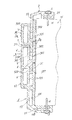
図1に示すように、実施形態のドア枠は、壁Wの第1の側面(又は内面)に固定される第1の顎部材1と、第1の顎部材1と伸縮自在又は摺動自在に係合可能で、壁Wの第2の側面(又は外面)に固定される第2の顎部材2と、を含む。
As shown in FIG. 1, the door frame of the embodiment includes a
各顎部材1又は2は、押出法によって作られ、プラスチック材料、又は他の適切な材料から作ることができる。顎部材1、2は、本実施形態に限定されず、ドアのわき柱、又はまぐさに設けられてもよい。添付の図面で示すとおり、要素はそれらの断面図で見られる。
Each
第1の顎部材1は、壁Wの第1の側面(又は内面)に固定される基部11と、基部11と一体的に形成される保持部13と、第2の顎部材2と伸縮自在又は摺動自在に係合するため保持部13から二股に分かれる留め部12と、を有する。基部11は、例えば、基部11に設けられた釘溝111を通して壁Wに釘Nを固定することによって固定され、釘溝111を覆う化粧片Sを有する。
The
基部11、保持部13、及び留め部12は、例えば押出法によって一体的に形成され、(断面が)台形の中空部110が基部11に形成され、断面が矩形形状の中空部131が保持部13に形成され、(断面が)矩形形状の補強中空突部120が留め部12に形成される。
The
このような中空部110、中空部131又は補強中空突部120は、押出法によって一体的に形成され、顎部材1の各々の部分11、13、12を補強するための剛性「箱形」構造を形づくる。
The
保持部13は、押出法によって第1の顎部材1が形成されるとき保持部13の中空部131に共押出しされる補強挿入部132をさらに含む。このような補強挿入部132は、ポリ塩化ビニル(PVC)片を含むプラスチック片から作られてもよく、ドアヒンジH及び保持部13を通して釘Nを壁Wの端壁D1に固定すると、補強挿入部132は、保持部13を補強し、図1に示すように、ドアヒンジH、ドアD、及びドア枠自身の壁Wへの固定を安定させるのに役立つ。
The
保持部13から二股に分かれる留め部12は、閉じるときにドアDを遅らせる補強中空突部120と、補強中空突部120に並ぶ裏当て留め具122と、を有し、第2の顎部材2と摺動自在に係合するため、補強中空突部120と裏当て留め具122との間に設けられる溝121を有する。
The fastening
補強中空突部120は、押出法によって第1の顎部材1と一体的に形成され、矩形形状の剛性「箱」又は「フレーム」を中空突部120に形成し、顎部材1及びドア枠を補強する。
The reinforcing
ドアを閉じるとき、ドアDと留め部12との間の隙間を塞ぐため、留め部12の補強中空突部120に密閉部材123が提供される。
When closing the door, a
従って、留め部12の補強中空突部120は、留め部12を補強し、また、閉じたときにドアDを抑えるための「ストッパ」として機能する。
Therefore, the reinforcing
中空部又は突部110、131、120の幾何学的形状は、本実施形態に限定されない。
The geometric shape of the hollow part or the
切り欠き又は凹部Vが、装飾目的で留め部12の表面に形成されてもよい。
A notch or recess V may be formed on the surface of the fastening
第2の顎部材2は、壁Wの第2の側面(又は外面)に固定可能な固定部21と、固定部21と一体的に形成され、壁Wの厚さに適合するため第1の顎部材1の留め部12に設けられた溝121と伸縮自在又は摺動自在に係合可能な係止部22とを含む。固定部21は、例えば、固定部21に設けられた釘溝211を通して壁Wに釘Nを固定することによって固定され、釘溝211を覆う化粧片Sを有する。
The
第2の顎部材2も、押出法によって形成され、プラスチック材料又は他の適切な材料から作ることができる。
The
本実施形態のドア枠を壁Wの戸口に取り付けるとき、第1の顎部材1は壁の内側面に固定され、第2の顎部材2は、壁Wの厚さに一致するまで、係止部22を第1の顎部材1の溝121と摺動自在又は伸縮自在に係合させ、そして壁の外側面に固定され、ドア枠と一体になる、又はドア枠を形成する。
When the door frame of this embodiment is attached to the door of the wall W, the
第2の顎部材2の係止部22は、第1の顎部材1の溝121内に隠れるため、2つの顎部材1、2の間に跡(track)又は隙間が表れず、ドア枠の外観が滑らかとなり、室内の装飾、又は内装効果に影響を及ぼさない。
Since the
第2の顎部材2の係止部22は、自由に、又は任意に、第1の顎部材1の溝121と係合可能で、それによって、現場で簡単に組み立てられるように壁Wの異なる厚さに任意に適合する。従って、本実施形態は、自由に調整して壁の厚さに一致させることができ、直接、速く、簡単に建築現場で取り付けられる組立式ドア枠としてよく機能する。
The locking
顎部材1、2は、例えば、押出法又は共押出法によって既製されるので、製作及び取付費用が、大幅に削減される。
Since the
なお、2つの顎部材1、2は、異なるドアの厚さ、ドアの幅、又はわき柱若しくはまぐさの垂直若しくは水平の寸法に適合するように調整されてもよい。
It should be noted that the two
図2及び3に示すように、より厚い壁のため、少なくとも1つの延長部材3が、第1の顎部材1と第2の顎部材2との間に挿入されてもよい。しかし、顎部材1、2の間に挿入される延長部材3の数は限定されない。
As shown in FIGS. 2 and 3, due to the thicker wall, at least one
延長部材3は、第1の顎部材1の溝121に伸縮自在又は摺動自在に係合可能な舌部31と、舌部31から二股に分かれ、第1の顎部材1の補強中空突部120と略一致する補強箱部320及び補強箱部320に並ぶ連結留め具322を有する分岐部32と、を有し、第2の顎部材2の係止部22と摺動自在に係合するため、補強箱部320と連結留め具322との間に設けられた溝を有する。
The
図2に示すように、延長部材3の舌部31を第1の顎部材1の溝121に係合させ、第2の顎部材2の係止部22を延長部材3の溝321に係合させることによって、第1の顎部材1と第2の顎部材2との間に延長部材3が挿入され、図1のものより大きな厚みを有するより幅の広いドアに適合する。
As shown in FIG. 2, the
壁W上でのドア枠の安定性又は固定強度を向上させるため、端壁D1と、裏当て留め具122又は連結留め具322との間に、パッキン又はパッドPが挿入されてもよく、そして釘Nが提供され、留め具322又は122を壁Wの端壁D1に固定する。
In order to improve the stability or fixing strength of the door frame on the wall W, a packing or pad P may be inserted between the end wall D1 and the
少なくとも1つの切り欠きVが、装飾のために補強箱部320の表面に形成され、全体の装飾性を向上させるため、補強箱部320と補強中空突部120との間の隙間Iを「偽装」(camouflage)する。
At least one notch V is formed on the surface of the
もしそのように1つ又は複数の切り欠きVによって偽装されなければ、隙間Iは、ドア枠の全体の装飾又は外観に影響を及ぼす破断線又は損傷により生じた細い隙間として間違われる虞がある。 If not so camouflaged by one or more notches V, the gap I may be mistaken for a broken line or a narrow gap caused by damage that affects the overall decoration or appearance of the door frame.
図3に示すように、第1の延長部材3及び第2の延長部材3aは、第1の顎部材1と第2の顎部材2との間に連続して挿入され、図2に示されたものより大きな厚みを有する幅の広いドアに適合する。
As shown in FIG. 3, the
延長部材3は、例えば押出法によって既製されてもよく、複数の延長部材3、3a...が提供されて厚い壁に適合し、広範囲の厚みの壁に対するドア枠の要求を満たす。
The
延長部材3及び3aの各々は、第1の顎部材1の溝121と摺動自在に係合可能な舌部31を有し、また、他の隣接する延長部材3の溝321と摺動自在に係合可能な舌部31を有し、そして図3に示すように、複数の延長部材は、連続してつながり、第1の顎部材1と第2の顎部材2との間に挿入される。
Each of the
同時に、延長部材3、3a各々の溝321は、第2の顎部材2の係止部22、又は延長部材の舌部31と摺動自在に係合可能である。
At the same time, the
因みに、図3に示されるように、第1の延長部材3は、第1の顎部材1の溝121と摺動自在に係合可能な舌部31を有し、第2の延長部材3aの他の舌部31と摺動自在に係合可能な溝321を有し、一方、第2の延長部材3aは、第2の顎部材2の係止部22と摺動自在に係合可能な溝321を有する。そして、2つの延長部材3、3aは、図3に示すような厚い壁Wに一致するように調整されたドア枠を形成するために、2つの顎部材1、2の間に連続して挿入される。
Incidentally, as shown in FIG. 3, the
本実施形態は、本発明の精神及び範囲から逸脱することなく改変してもよい。 The embodiments may be modified without departing from the spirit and scope of the invention.
1 第1の顎部材、
11 基部、
110 中空部、
111 釘溝、
12 留め部、
120 補強中空突部、
122 裏当て留め具、
13 保持部、
131 中空部、
132 補強挿入部、
2 第2の顎部材、
21 固定部、
211 釘溝、
22 係止部、
3、3a 延長部材、
31 舌部、
32 分岐部、
320 補強箱部、
321 溝、
322 連結留め具、
N 釘、
P パッキン、
S 化粧片、
V 凹部、
W 壁。
1 first jaw member,
11 base,
110 hollow part,
111 nail groove,
12 clasp,
120 reinforced hollow protrusions,
122 backing fasteners,
13 holding part,
131 hollow part,
132 Reinforcing insert,
2 second jaw member,
21 fixing part,
211 nail groove,
22 locking part,
3, 3a extension member,
31 tongue,
32 branching section,
320 reinforcement box,
321 groove,
322 connecting fasteners,
N nails,
P packing,
S makeup pieces,
V recess,
W Wall.
Claims (13)
前記第1の顎部材と伸縮自在又は摺動自在に係合して前記壁の厚さに適合する、前記壁の第2の側面に固定されてドア枠を形成する第2の顎部材と、を有し、
前記第1の顎部材及び前記第2の顎部材の各々が押出法によって形成される、ドア枠。 A first jaw member fixed to the first side of the wall;
A second jaw member fixed to the second side surface of the wall to form a door frame, which is telescopically or slidably engaged with the first jaw member and adapted to the thickness of the wall; Have
A door frame in which each of the first jaw member and the second jaw member is formed by an extrusion method.
Applications Claiming Priority (1)
| Application Number | Priority Date | Filing Date | Title |
|---|---|---|---|
| TW98106018 | 2009-02-25 |
Publications (1)
| Publication Number | Publication Date |
|---|---|
| JP2010196466A true JP2010196466A (en) | 2010-09-09 |
Family
ID=42629670
Family Applications (1)
| Application Number | Title | Priority Date | Filing Date |
|---|---|---|---|
| JP2010037613A Pending JP2010196466A (en) | 2009-02-25 | 2010-02-23 | Adjustable modular doorframe |
Country Status (3)
| Country | Link |
|---|---|
| US (1) | US20100212239A1 (en) |
| JP (1) | JP2010196466A (en) |
| TW (1) | TW201031809A (en) |
Cited By (2)
| Publication number | Priority date | Publication date | Assignee | Title |
|---|---|---|---|---|
| JP2016132884A (en) * | 2015-01-16 | 2016-07-25 | 株式会社 サンキョウエポック | Butt end cover device on frontage |
| JP2016199939A (en) * | 2015-04-13 | 2016-12-01 | パナソニックIpマネジメント株式会社 | Cover material |
Families Citing this family (21)
| Publication number | Priority date | Publication date | Assignee | Title |
|---|---|---|---|---|
| IT1406665B1 (en) * | 2011-02-09 | 2014-03-07 | Maria De | EXTENSIBLE DEVICE FOR BUILDING CONSTRUCTION. |
| US9068391B2 (en) * | 2012-04-05 | 2015-06-30 | MarPec, Inc. | Adjustable garage door jamb trim |
| US9080373B2 (en) * | 2012-08-23 | 2015-07-14 | Forest View Industries Ltd. | Jamb system |
| US9194170B2 (en) * | 2013-03-15 | 2015-11-24 | Therma-Tru Corp. | Jamb installation device and method |
| CN103410406B (en) * | 2013-08-24 | 2015-07-08 | 程礼中 | Door and window sleeve capable of cut and closed up |
| CN104594762B (en) * | 2014-11-21 | 2016-08-24 | 广西福美耀节能门窗有限公司 | A kind of secondary frame of adjustable width |
| FR3037983B1 (en) * | 2015-06-24 | 2018-11-16 | Team-Alter | NEW OR RENOVATION HAULING |
| US10648219B2 (en) * | 2015-08-25 | 2020-05-12 | Uniline Australia Limited | Window, shutter or door with adjustable mounting frame |
| CA3017209C (en) * | 2016-03-11 | 2023-09-26 | Masonite Corporation | Devices and methods for mounting door frames |
| US10480240B2 (en) * | 2016-06-08 | 2019-11-19 | Masonite Corporation | Door kits and related methods |
| AU2016100994A4 (en) * | 2016-07-04 | 2016-07-28 | Inter-Join Pty Ltd | Reinforced split door jamb and method of installation |
| GB2554060A (en) * | 2016-08-15 | 2018-03-28 | Kingsway Entpr Uk Ltd | Door frame |
| JP6999476B2 (en) | 2018-03-30 | 2022-01-18 | 株式会社Lixil | Joinery |
| EP3816388A1 (en) * | 2018-06-26 | 2021-05-05 | Madecat, S.C.P. | Profile for door casings and door casing comprising said profile |
| TWI681107B (en) * | 2018-06-27 | 2020-01-01 | 台灣門框科技有限公司 | Extensible wall frame |
| ES2737629A1 (en) * | 2018-07-11 | 2020-01-15 | Portillo Constancio Rodriguez | Adjustable fence system from modular aluminum profiles (Machine-translation by Google Translate, not legally binding) |
| CN109667510A (en) * | 2019-01-23 | 2019-04-23 | 浙江艾格新材料科技有限公司 | A kind of card slot type door sleeve and installation method |
| WO2021064257A1 (en) * | 2019-09-30 | 2021-04-08 | Rodriguez Portillo Constancio | Adjustable frame system from modular aluminium profiles |
| IT202000004192A1 (en) * | 2020-02-28 | 2021-08-28 | Henry Glass S R L | ALUMINUM JAMB FOR INTERIOR DOOR |
| NL2027870B1 (en) * | 2021-03-30 | 2022-10-12 | Paulus Van Den Einden Johannes | Door frame comprising a frame post and a wall clamp attached thereto |
| US20220389749A1 (en) * | 2021-06-07 | 2022-12-08 | Aadg, Inc. | Adjustable frame with a thermal break seal |
Citations (10)
| Publication number | Priority date | Publication date | Assignee | Title |
|---|---|---|---|---|
| JPS5093735U (en) * | 1973-12-26 | 1975-08-06 | ||
| JPS57117179U (en) * | 1981-01-12 | 1982-07-20 | ||
| JPS57172883U (en) * | 1981-04-27 | 1982-10-30 | ||
| JPS5938383U (en) * | 1982-09-02 | 1984-03-10 | ニホンフラツシユ株式会社 | Door frame installation structure |
| JPS6041474U (en) * | 1983-08-31 | 1985-03-23 | 三協アルミニウム工業株式会社 | shoe slide |
| JPS6143383U (en) * | 1984-08-25 | 1986-03-20 | 松下電工株式会社 | door frame |
| JPH01158175A (en) * | 1987-12-16 | 1989-06-21 | Tosutemu Sera Kk | Bending member for construction |
| JPH06167170A (en) * | 1992-11-27 | 1994-06-14 | Misawa Homes Co Ltd | Decorative frame for front door sash |
| JPH1113350A (en) * | 1997-06-25 | 1999-01-19 | Sasakura Eng Co Ltd | Method and device for attaching fitting frame to concrete wall in building |
| JP2000045634A (en) * | 1998-07-27 | 2000-02-15 | Matsushita Electric Works Ltd | Door outer frame architrave |
Family Cites Families (16)
| Publication number | Priority date | Publication date | Assignee | Title |
|---|---|---|---|---|
| US1855470A (en) * | 1929-06-21 | 1932-04-26 | Bilton Percy | Door |
| US2736930A (en) * | 1953-10-28 | 1956-03-06 | John D Longley | Door frame |
| US3545135A (en) * | 1969-04-10 | 1970-12-08 | Philip Ben Lieber | Door jamb |
| US3800488A (en) * | 1972-02-16 | 1974-04-02 | C Swanson | Door jamb with mitered joints and l-shaped brackets |
| US4589229A (en) * | 1981-01-07 | 1986-05-20 | Warren Lawrence L | Adjustable door jamb assembly |
| US5528869A (en) * | 1989-11-18 | 1996-06-25 | Boomer; Kenneth R. | Building product |
| US5070651A (en) * | 1991-01-04 | 1991-12-10 | Jeter Gregory L | Door frame assembly |
| US5365708A (en) * | 1993-02-23 | 1994-11-22 | Jenkins Manufacturing Co., Inc. | Door frame system |
| US5412909A (en) * | 1993-04-05 | 1995-05-09 | Wu; Ming-Hsin | Plastic casing for a door frame |
| JP3259218B2 (en) * | 1997-02-28 | 2002-02-25 | 株式会社住建産業 | Width adjustment frame material |
| US6308476B1 (en) * | 1998-08-25 | 2001-10-30 | Kabushiki Kaisha Juken Sangyo | Adjustable frame |
| TW422911B (en) * | 1998-09-22 | 2001-02-21 | Sesame Door Co Ltd | Quick-fixing construction method for doorframe of prefabricated wall panel |
| TW200702540A (en) * | 2005-07-06 | 2007-01-16 | Sesame Door Co Ltd | Construction method for fast fixing door frame after wall has been constructed and product thereof |
| TWM319309U (en) * | 2007-03-30 | 2007-09-21 | Jin-Shu Chen | Door frame material stretchable according to thickness of wall |
| CN201106357Y (en) * | 2007-09-20 | 2008-08-27 | 浙江伊佳特门业有限公司 | Door frame of indoor door |
| TWM336327U (en) * | 2007-12-28 | 2008-07-11 | Juh Jy Yuan Entpr Co Ltd | Structure of doorcase |
-
2009
- 2009-08-18 TW TW098127733A patent/TW201031809A/en unknown
- 2009-12-08 US US12/592,981 patent/US20100212239A1/en not_active Abandoned
-
2010
- 2010-02-23 JP JP2010037613A patent/JP2010196466A/en active Pending
Patent Citations (10)
| Publication number | Priority date | Publication date | Assignee | Title |
|---|---|---|---|---|
| JPS5093735U (en) * | 1973-12-26 | 1975-08-06 | ||
| JPS57117179U (en) * | 1981-01-12 | 1982-07-20 | ||
| JPS57172883U (en) * | 1981-04-27 | 1982-10-30 | ||
| JPS5938383U (en) * | 1982-09-02 | 1984-03-10 | ニホンフラツシユ株式会社 | Door frame installation structure |
| JPS6041474U (en) * | 1983-08-31 | 1985-03-23 | 三協アルミニウム工業株式会社 | shoe slide |
| JPS6143383U (en) * | 1984-08-25 | 1986-03-20 | 松下電工株式会社 | door frame |
| JPH01158175A (en) * | 1987-12-16 | 1989-06-21 | Tosutemu Sera Kk | Bending member for construction |
| JPH06167170A (en) * | 1992-11-27 | 1994-06-14 | Misawa Homes Co Ltd | Decorative frame for front door sash |
| JPH1113350A (en) * | 1997-06-25 | 1999-01-19 | Sasakura Eng Co Ltd | Method and device for attaching fitting frame to concrete wall in building |
| JP2000045634A (en) * | 1998-07-27 | 2000-02-15 | Matsushita Electric Works Ltd | Door outer frame architrave |
Cited By (2)
| Publication number | Priority date | Publication date | Assignee | Title |
|---|---|---|---|---|
| JP2016132884A (en) * | 2015-01-16 | 2016-07-25 | 株式会社 サンキョウエポック | Butt end cover device on frontage |
| JP2016199939A (en) * | 2015-04-13 | 2016-12-01 | パナソニックIpマネジメント株式会社 | Cover material |
Also Published As
| Publication number | Publication date |
|---|---|
| US20100212239A1 (en) | 2010-08-26 |
| TW201031809A (en) | 2010-09-01 |
| TWI502127B (en) | 2015-10-01 |
Similar Documents
| Publication | Publication Date | Title |
|---|---|---|
| JP2010196466A (en) | Adjustable modular doorframe | |
| USD817149S1 (en) | Slide clip with internal and external flanges | |
| USD814905S1 (en) | Slide clip with internal and external flanges | |
| AU2020100244A4 (en) | Improvements in snap fit posts for fence panels balustrades and the like | |
| US9238937B2 (en) | Flashing and joiner for window installations | |
| ATE479798T1 (en) | COMBI PILLOW WALL | |
| US8733041B2 (en) | Window insert system and associated methods | |
| US2454523A (en) | Door casement and method of forming the same | |
| ATE517299T1 (en) | HOUSEHOLD APPLIANCE | |
| US9995080B2 (en) | Door jamb for flush in-swing door | |
| USD601369S1 (en) | Embossed panel | |
| US20140102035A1 (en) | Brick mold assembly, connector for same and kit for assembly of same | |
| USD582565S1 (en) | Door panel | |
| US20080222979A1 (en) | Frame Extension | |
| JP2016037804A (en) | Water cut-off member and exterior wall structure | |
| ATE539222T1 (en) | BUILDING CLOSURE ELEMENT WITH A THERMALLY SEPARATED FRAME EQUIPPED WITH AN L-SHAPED SEALING PROFILE | |
| KR20100131845A (en) | Interior decoration panel of construction | |
| USD582566S1 (en) | Door panel | |
| USD574971S1 (en) | Embossed panel | |
| ITAN20140033U1 (en) | PERFECT ARMORED DOOR. | |
| US20030000169A1 (en) | Corner key with angled ribs | |
| US20120031023A1 (en) | Frame construction for a fenestration | |
| KR950014521A (en) | Easy door frame and construction method | |
| USD581059S1 (en) | Door panel | |
| US20220074227A1 (en) | Barrier assembly |
Legal Events
| Date | Code | Title | Description |
|---|---|---|---|
| A131 | Notification of reasons for refusal |
Free format text: JAPANESE INTERMEDIATE CODE: A131 Effective date: 20120207 |
|
| A521 | Written amendment |
Free format text: JAPANESE INTERMEDIATE CODE: A523 Effective date: 20120507 |
|
| A131 | Notification of reasons for refusal |
Free format text: JAPANESE INTERMEDIATE CODE: A131 Effective date: 20120814 |
|
| A521 | Written amendment |
Free format text: JAPANESE INTERMEDIATE CODE: A523 Effective date: 20121112 |
|
| A02 | Decision of refusal |
Free format text: JAPANESE INTERMEDIATE CODE: A02 Effective date: 20130326 |