JP2010193453A - Receiver for connecting to current interface, and method for detecting data signal from current signal - Google Patents
Receiver for connecting to current interface, and method for detecting data signal from current signal Download PDFInfo
- Publication number
- JP2010193453A JP2010193453A JP2010030088A JP2010030088A JP2010193453A JP 2010193453 A JP2010193453 A JP 2010193453A JP 2010030088 A JP2010030088 A JP 2010030088A JP 2010030088 A JP2010030088 A JP 2010030088A JP 2010193453 A JP2010193453 A JP 2010193453A
- Authority
- JP
- Japan
- Prior art keywords
- signal
- reference voltage
- current
- difference signal
- difference
- Prior art date
- Legal status (The legal status is an assumption and is not a legal conclusion. Google has not performed a legal analysis and makes no representation as to the accuracy of the status listed.)
- Pending
Links
Images
Classifications
-
- H—ELECTRICITY
- H04—ELECTRIC COMMUNICATION TECHNIQUE
- H04L—TRANSMISSION OF DIGITAL INFORMATION, e.g. TELEGRAPHIC COMMUNICATION
- H04L25/00—Baseband systems
- H04L25/38—Synchronous or start-stop systems, e.g. for Baudot code
- H04L25/40—Transmitting circuits; Receiving circuits
-
- G—PHYSICS
- G08—SIGNALLING
- G08C—TRANSMISSION SYSTEMS FOR MEASURED VALUES, CONTROL OR SIMILAR SIGNALS
- G08C19/00—Electric signal transmission systems
- G08C19/02—Electric signal transmission systems in which the signal transmitted is magnitude of current or voltage
Abstract
Description
本発明は、電流インターフェースに接続するための受信装置、および電流信号を受信するための方法、ならびにこのような受信装置を備える制御装置、およびこのような受信装置と少なくとも1つの送信機からなる装置に関する。 The invention relates to a receiving device for connecting to a current interface, a method for receiving a current signal, a control device comprising such a receiving device, and a device comprising such a receiving device and at least one transmitter. About.
センサまたは他の周辺機器からのデータないし信号を中央制御装置(ECU)に伝送するために、いくつかのシステムにおいては電流インターフェースが使用され、この電流インターフェースは単方向または双方向とすることができる。このようなセンサシステムはとりわけ車両の乗員保護システムにおいて、例えばエアバック制御のために使用される。DE102004013597A1はこのようなセンサシステムを開示しており、このセンサシステムは、制御システムと、単方向電流インターフェースによって接続されたセンサとを備えており、このセンサはPAS3またはPAS4という名称でも公知である。 In some systems, a current interface is used to transmit data or signals from sensors or other peripherals to a central control unit (ECU), which can be unidirectional or bidirectional. . Such sensor systems are used in particular in vehicle occupant protection systems, for example for airbag control. DE 102004013597A1 discloses such a sensor system, which comprises a control system and a sensor connected by a unidirectional current interface, which sensor is also known under the name PAS3 or PAS4.
電流供給は、このようなシステムの場合には一般的に、制御装置の受信装置から伝達される。受信装置は例えば専用のASICとして構成することができ、センサ静電流およびセンサデータ流から構成されるインターフェース電流を出力する。したがってセンサは、自身の測定に基づいてセンサ静電流を変調することができる。新型のシステムにおいては、同期バス動作において複数のセンサを共通の1つの受信装置に接続することができる。したがって受信装置における電流は、全てのセンサの電流受容、ならびに、実際に送信しているセンサの変調された送信電流から構成されている。 In the case of such a system, the current supply is generally transmitted from the receiving device of the control device. The receiving device can be configured as a dedicated ASIC, for example, and outputs an interface current composed of a sensor static current and a sensor data stream. Thus, the sensor can modulate the sensor static current based on its own measurements. In newer systems, multiple sensors can be connected to a common receiver in synchronous bus operation. Thus, the current in the receiving device consists of the current acceptance of all sensors as well as the modulated transmission current of the sensor that is actually transmitting.
送信電流を変調するためのセンサの駆動強度、および、送信機と受信器との間のバスシステムにおける負荷は種々異なるので、送信電流の許容範囲は比較的大きい。したがって受信装置は、比較的大きな許容範囲を備える信号を、解釈すべき信号形態にて受信する。 Since the driving strength of the sensor for modulating the transmission current and the load in the bus system between the transmitter and the receiver are different, the allowable range of the transmission current is relatively large. Therefore, the receiving apparatus receives a signal having a relatively large allowable range in a signal form to be interpreted.
データ信号を伝送路を介して伝送するために、とりわけ例えばマンチェスタ符号化のような位相位置変調による伝送路符号化が公知である。例えば長方形信号の、または(エッジ急峻度が有限であることを考慮した場合には)台形信号の受信信号は、受信装置においてその後再び相応のデータ信号に符号化ないし復号化される。これに加えて受信コンパレータは、受信した受信信号を基準電圧と比較する。しかしながら各信号に対して正確に調整すべき閾値は既知ではなく、送信機の信号が異なる場合には種々異なり得る。 In order to transmit a data signal via a transmission line, transmission line coding by means of phase position modulation, for example Manchester coding, is known. For example, the received signal of a rectangular signal or of a trapezoidal signal (in view of the finite edge steepness) is then encoded or decoded again into a corresponding data signal in the receiving device. In addition to this, the reception comparator compares the received signal received with a reference voltage. However, the threshold to be accurately adjusted for each signal is not known and can be different if the transmitter signal is different.
本発明によれば、受信コンパレータにおいて受信信号と比較するために使用される、閾値として機能する基準電圧が、受信コンパレータから出力される差信号の評価に基づいて調整される。このようにすれば、例えば検出された受信信号の上下の電圧レベルを平均することによる基準電圧の簡単な調整に比べて、基準電圧をより正確に検出することができる。 According to the present invention, the reference voltage functioning as a threshold value used for comparison with the reception signal in the reception comparator is adjusted based on the evaluation of the difference signal output from the reception comparator. In this way, the reference voltage can be detected more accurately than a simple adjustment of the reference voltage, for example, by averaging the upper and lower voltage levels of the detected received signal.
本発明によれば、とりわけ信号経過の評価を行うことができる。これに加え、とりわけ測定期間において差信号に含まれるハイビットとロービットを量的に評価することができる;すなわちこれは、測定期間における差信号のハイ電圧レベルとロー電圧レベルの全体幅の評価に相当する。 According to the present invention, signal progress can be evaluated in particular. In addition, the high and low bits contained in the difference signal can be evaluated quantitatively, especially during the measurement period; that is, this corresponds to an evaluation of the overall width of the high and low voltage levels of the difference signal during the measurement period. To do.
本発明によれば、とりわけ電流変調された信号の特有の伝送路符号化を利用することができる。とりわけ、出力データ信号の位相位置の変調が行われるマンチェスタ符号化の場合、理想的にハイビットとロービットの数は−充分長い測定期間に亘って−同じである。本発明によれば、このように差信号が、充分な評価期間ないし測定期間に亘って同数のハイビットとロービットを有するか否かをチェックすることができるということが認識される。そして基準電圧の追従制御によって、ハイビットとロービットの数を相応に変化させることができる。したがってロービットの数よりも多いハイビットの数を検出した場合には、基準電圧を上昇させることができ、ハイビットの数よりも多いロービットの数を検出した場合には、相応にして基準電圧を低減することができる。 According to the present invention, it is possible to use, among other things, unique transmission line coding of current-modulated signals. In particular, in the case of Manchester coding where the phase position of the output data signal is modulated, the number of high bits and low bits is ideally the same over a sufficiently long measurement period. In accordance with the present invention, it is recognized that it can thus be checked whether the difference signal has the same number of high bits and low bits over a sufficient evaluation period or measurement period. The number of high bits and low bits can be changed accordingly by reference voltage tracking control. Therefore, the reference voltage can be increased when the number of high bits larger than the number of low bits is detected, and when the number of low bits larger than the number of high bits is detected, the reference voltage is reduced accordingly. be able to.
したがって本発明によれば、いくつかの利点が達成される。構造的に簡単でありながら、基準電圧の追従制御のために効果的な閉ループ制御回路が形成される。本発明によれば、検出された差信号の符号化ないし復号化の前に、ひいては、データ内容の評価の前に、低コストの追従制御によって、信号の質を格段に改善することができる。このような追従制御は、本発明によれば、とりわけ種々異なるチャネルないし送信機のために実施することができる。本発明によれば、検出された基準電圧をそれぞれのチャネルに割り当て、記憶することができる。 Thus, according to the present invention, several advantages are achieved. While being structurally simple, an effective closed loop control circuit is formed for tracking control of the reference voltage. According to the present invention, the signal quality can be remarkably improved by low-cost tracking control before encoding or decoding of the detected difference signal and thus before the evaluation of the data content. Such tracking control can be carried out according to the invention, especially for different channels or transmitters. According to the present invention, the detected reference voltage can be assigned to each channel and stored.
量的評価によって、基準電圧の調整に対する非常に高い精度を達成することができる。このために必要な測定期間は複数のビットを含むことができ、若干数のビット、例えば10ないし20個のビットによるだけで、閾値として機能する基準電圧の調整を格段に改善することができる。 By quantitative evaluation, a very high accuracy for the adjustment of the reference voltage can be achieved. The measurement period required for this can include a plurality of bits, and the adjustment of the reference voltage functioning as a threshold can be significantly improved with only a few bits, for example 10 to 20 bits.
とりわけ、種々異なり得る複数のセンサを用いたシステムにおけるフレキシブルかつ確実な検出が、ただ1つの受信装置において、受信装置を事前に正確に基準電圧に調整したり、場合によってはプログラミングしたりする必要なく可能となる。バスシステムにおいて起こり得る障害や変更をフレキシブルに修正することができるので、本発明によれば、自動的に適合可能な受信装置を達成することができる。 In particular, flexible and reliable detection in systems with different sensors, which can vary, eliminates the need to precisely adjust the receiver in advance to a reference voltage or possibly be programmed in a single receiver. It becomes possible. Since possible failures and changes in the bus system can be flexibly corrected, according to the present invention, it is possible to achieve a receiving device that can be automatically adapted.
基本的に本発明によれば、ハイビットとロービットの数の量的評価を、他の位相位置変調された符号化のため、たとえば差分マンチェスタ符号化またはBiphase-Mark-Code方式のために実施することもできる。 Basically according to the present invention, a quantitative evaluation of the number of high and low bits is performed for other phase position modulated coding, for example for differential Manchester coding or Biphase-Mark-Code scheme. You can also.
本発明による受信装置は、ハードウェア的に構成されるが、しかしながらとりわけ例えば差評価装置をソフトウェア的に構成し、後続のマンチェスタ符号化ないしマンチェスタ復号化のための符号化装置によって実現することもできる。受信コンパレータは基本的に構成上、2つのアナログ電圧を比較するための任意の比較回路とすることができる。 The receiving device according to the present invention is configured in hardware, however, in particular, for example, the difference evaluation device can also be configured in software and realized by a subsequent Manchester encoding or encoding device for Manchester decoding. . The receiving comparator basically has a configuration and can be an arbitrary comparison circuit for comparing two analog voltages.
図面において、同様または相応するエレメントには同一または同様の参照符号が付されている。 In the drawings, similar or corresponding elements are provided with the same or similar reference signs.
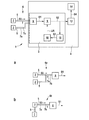
図1によれば回路装置1は、少なくとも1つのセンサ2、例えばマイクロメカニカルセンサ2と、中央制御装置(ECU)4とを有する。中央制御装置4は受信装置3を有し、該受信装置3は電流インターフェース6を介してセンサ2と接続されている。電流インターフェース6は、ここでは少なくとも1つのバス接続5を備えるバスシステム6として構成されている。バス接続5は、2つの線路7aおよび7bを備える2線バス接続5として構成することができ、これら2つの線路を介してインターフェース電流Iが流れる。この際センサ2は、インターフェース電流Iにおいて電流変調によって電流信号S0を形成し、このようにして本発明による送信機を表している。
According to FIG. 1, the
本発明によれば、図1のように中央制御装置4にとりわけ複数のセンサ2を接続することもでき、バスシステム6は2つ以上のバス接続5を有する。
According to the invention, it is also possible to connect a plurality of
受信装置3は、例えば別個の受信ICとして構成することも、制御装置4に組み込むこともできる。受信装置3は接続装置8を有し、該接続装置8は、例えばここでは説明しない公知のやり方で、インターフェース電流Iを生成するための電流源と、変調された電流信号S0を検出するための電圧検出器とを有する。
The
図1aおよび1bは、別のバスシステム6bおよび6bを有する、図1のブロック図の一部分を示す。これらの図においては、見易さの観点から、図1のその他の要素は省略されている。図1aでは、複数のセンサ2が共通の線路7aおよび7bに接続されており、接続装置8は、唯一のバス接続5のためにただ1つの接続部を有する。図1bでは、複数のセンサ2がチェーンとして連続して接続されており、ここでも接続装置8は、唯一のバス接続5のためにただ1つの接続部を有する。以下、図1と関連させて本願発明をさらに詳細に説明する。
FIGS. 1a and 1b show a portion of the block diagram of FIG. 1 having
各センサ2はそれぞれ電流変調回路を有し、該電流変調回路は、接続装置8から出力される静電流を変調し、これによって電流信号S0を接続装置8に伝送する。したがって各センサ2を、該センサ自身の別個のエネルギー供給部ないし電圧源無しに構成し、インターフェース電流Iによって給電することができる。
Each
接続装置8は電流信号S0を受信し、電圧信号として受信信号S1を受信コンパレータ9に出力する。受信コンパレータ9はさらに、基準電圧源10からの基準電圧URを受容する。受信コンパレータ9は、受信信号S1を、閾値として利用される基準電圧URと比較し、この比較結果に基づいてマンチェスタ符号器12に差信号S2を出力する。
The
センサ2は、マンチェスタ符号化によって電流信号S0を出力する。マンチェスタ符号化自体は公知であり、伝送すべき信号の位相位置の変調を引き起こす伝送路符号を表している。マンチェスタ符号化においては、符号化すべきデータ信号のハイビットおよびロービットが、マンチェスタ符号のビットの上昇エッジないし下降エッジによって描写され、その間には潜在エッジ(Kann-Flanken)が設けられており、この潜在エッジは、データ情報を伝送せず、2つの上昇エッジの間の移行または2つの下降エッジの間の移行のために使用される。
The
したがって受信信号S1も差信号S2も、マンチェスタ符号化されている。マンチェスタ符号器12はマンチェスタ符号化ないし復号化を実施し、データ信号S4を、受信装置4の別の装置14に出力する。この装置14は、例えばデータ信号S4の評価を実施することができる。
Therefore, both the reception signal S1 and the difference signal S2 are Manchester encoded. The
センサ2と受信装置3の間のバス接続5においては駆動強度および負荷が異なるので、電流信号S0の比較的大きな許容範囲が生じる。したがって受信装置3は、比較的大きな許容範囲を備える電流信号S0を、解釈すべき信号形態にて受信する。閾値の正確な位置、すなわち設定すべき基準電圧URの高さは、種々のセンサ2毎に異なり得るが、場合によってはそれぞれのセンサ2毎に時間によっても異なり得る。
In the
本発明によれば、マンチェスタ符号化の場合、電流信号S0ないし該電流信号から得られる電圧信号としての受信信号S1において同数のハイビットHおよびロービットLが存在する、ということが利用される。したがってマンチェスタ符号信号は、−場合によっては充分に多いビットの後で−それぞれ常に同数のハイビットおよびロービットを有する。 According to the present invention, in the case of Manchester encoding, it is used that the same number of high bits H and low bits L exist in the current signal S0 or the received signal S1 as a voltage signal obtained from the current signal. The Manchester code signal therefore always has the same number of high and low bits, possibly after enough bits.
したがって本発明によれば、差信号S2が差評価装置15に供給され、差評価装置15は、図2に関連して記載された方法に基づいて差信号S2を評価し、制御信号S3を基準電圧源10に出力する。
Thus, according to the invention, the difference signal S2 is supplied to the
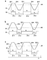
図2の線図a,b,cは、それぞれ異なる基準電圧URないし識別閾値を備える非理想的な受信信号S1の、測定期間Δtにわたる時間経過と、ここから導出される差信号S2とを示す。 The diagrams a, b, c of FIG. 2 show the time course of the non-ideal received signal S1 with different reference voltages UR or discrimination thresholds over the measurement period Δt and the difference signal S2 derived therefrom. .
受信コンパレータ9は、線図a,b,cにおいて、受信信号S1がそれぞれの基準電圧URの上にあるか下にあるかに応じて、それぞれハイ信号またはロー信号を出力する。図2aでは、基準電圧URは、台形の受信信号S1の比較的上方に位置している。受信信号S1の第1上昇エッジ20−1と第1下降エッジ20−2との間には、信号領域として、狭幅のハイ領域21−1が形成される。これに続いて前記下降エッジ20−2と第2上昇エッジ20−3との間においては、比較的幅広のロー領域21−2が形成され、この後相応にして、次の下降エッジ20−4まではハイ領域21−3が、下降エッジ20−5までは比較的幅広のロー領域21−4が後続する。このように、形成された差信号S2においては、ロー領域の全体幅はハイ領域の全体幅よりも広くなっている。したがってビットを領域に割り当てる場合、例えば領域21−1に1つのハイビットHを割り当て、領域21−2に2つのロービットLを割り当てる場合には、ロービットLはハイビットHよりも多く形成されることとなる。したがって差信号S1から直接、基準電圧URが高過ぎに設定されているということが認識できるのである。
In the diagrams a, b, and c, the
図2の線図bは、基準電圧URが低過ぎる場合、すなわち設定された識別閾値が低過ぎる場合における相応の事例を示す。幅広のハイ領域21−1が形成され、これに狭幅のロー領域21−2と非常に幅広のハイ領域21−3が後続する。したがってビットを割り当てる場合には、差信号S2において、ハイビットHはロービットLよりも多く形成される。 The diagram b of FIG. 2 shows a corresponding case when the reference voltage UR is too low, ie when the set identification threshold is too low. A wide high region 21-1 is formed, followed by a narrow low region 21-2 and a very wide high region 21-3. Therefore, when assigning bits, more high bits H are formed than low bits L in the difference signal S2.
図2の線図cは、正しく調整された基準電圧URによる、受信信号S1の識別を示している。差信号S2において、同じ幅のハイ領域とロー領域、すなわち同数のハイビットHとロービットLが形成される。 The diagram c in FIG. 2 shows the identification of the received signal S1 with a correctly adjusted reference voltage UR. In the difference signal S2, a high region and a low region having the same width, that is, the same number of high bits H and low bits L are formed.
このように、図2aの場合には差評価装置15は、差信号S2において、測定期間ΔtにわたってハイビットHの数がロービットLの数より少ないことを検出し、そしてURを低下させるために制御信号S3を基準電圧源10に供給する。これに続いて例えば差信号S2が図2bに相応して出力される場合には、差評価装置15は、URが低過ぎに設定されたことを認識し、相応の制御信号S3を基準電圧源10に供給して、基準電圧URを上昇させ、基準電圧URを先行する前記2つの値の間に設定する。このようにして装置9,15,10は、基準電圧URを調整ないし追従制御するための閉ループ制御システムを形成している。このようにして図2の線図cに相応する差信号S2を、図示した非理想的な受信信号S1の場合においても正しく調整することができ、したがってマンチェスタ符号器12は、続いてデータ信号S4への符号化ないし復号化を実施することができる。
Thus, in the case of FIG. 2a, the
Claims (14)
前記接続装置(8)は、前記電流インターフェース(6,6a,6b)を介して電流信号(S0)を受信し、かつ電圧信号としての受信信号(S1)を出力し、
前記基準電圧源(10)は、基準電圧(UR)を出力し、
前記受信コンパレータ(9)は、前記受信信号(S1)と前基準電圧(UR)を受信し、かつ差信号(S1)を出力する、
形式の受信装置において、
前記基準電圧源(10)は、前記基準電圧(UR)を、前記差信号(S2)の評価に基づいて調整する、
ことを特徴とする受信装置。 A receiving device for connecting to a current interface (6, 6a, 6b), comprising at least a connecting device (8), a reference voltage source (10) and a receiving comparator (9),
The connection device (8) receives a current signal (S0) via the current interface (6, 6a, 6b) and outputs a reception signal (S1) as a voltage signal;
The reference voltage source (10) outputs a reference voltage (UR),
The reception comparator (9) receives the reception signal (S1) and the previous reference voltage (UR) and outputs a difference signal (S1).
In the receiving device of the format
The reference voltage source (10) adjusts the reference voltage (UR) based on the evaluation of the difference signal (S2).
A receiving apparatus.
ことを特徴とする請求項1記載の受信装置。 The receiver includes a closed loop control circuit (9, 15, 10) for adjusting the difference signal (S2) according to a change in the reference voltage (UR).
The receiving apparatus according to claim 1.
ことを特徴とする請求項1または2記載の受信装置。 The received signal (S1) is phase-position modulated.
The receiving apparatus according to claim 1 or 2, wherein
前記差信号(S2)を受信し、
測定期間(Δt)における該差信号(S2)のハイビット(H)および/またはロービット(L)の数から、および/または、測定期間(Δt)における差信号(S2)のハイ電圧レベルの総期間およびロー電圧レベルの総期間から、現在調整されている基準電圧(UR)を評価し、
この評価に基づいて制御信号(S3)を、基準電圧(UR)を出力するための前記基準電圧源(10)に出力する、
ことを特徴とする請求項1〜3のいずれか一項記載の受信装置。 The receiver has a difference evaluation device (15), and the difference evaluation device (15)
Receiving the difference signal (S2);
From the number of high bits (H) and / or low bits (L) of the difference signal (S2) in the measurement period (Δt) and / or the total period of the high voltage level of the difference signal (S2) in the measurement period (Δt) And the current adjusted reference voltage (UR) from the total duration of the low voltage level,
Based on this evaluation, a control signal (S3) is output to the reference voltage source (10) for outputting a reference voltage (UR).
The receiving device according to any one of claims 1 to 3, wherein
前記測定期間(Δt)における前記ロービット(L)の数が前記ハイビット(H)の数よりも多い場合、および/または、前記ロー電圧レベルの総期間が前記ハイ電圧レベルの総期間よりも長い場合には、前記差評価装置(15)が、前記基準電圧(UR)を低減させるための制御信号(S3)を出力する、
ことを特徴とする請求項4記載の受信装置。 When the number of high bits (H) in the measurement period (Δt) is larger than the number of low bits (L), and / or when the total period of the high voltage level is longer than the total period of the low voltage level The difference evaluation device (15) outputs a control signal (S3) for increasing the reference voltage (UR),
When the number of low bits (L) in the measurement period (Δt) is larger than the number of high bits (H) and / or when the total period of the low voltage level is longer than the total period of the high voltage level The difference evaluation device (15) outputs a control signal (S3) for reducing the reference voltage (UR).
The receiving apparatus according to claim 4.
前記接続装置(8)は、前記バスシステム(6,6a,6b)の少なくとも2つの送信機に接続するために設けられている、
ことを特徴とする請求項1〜5のいずれか一項記載の受信装置。 The current interface (6, 6a, 6b) is configured as a bus system (6, 6a, 6b) comprising a plurality of bus connections (5),
The connection device (8) is provided for connecting to at least two transmitters of the bus system (6, 6a, 6b),
The receiving apparatus according to claim 1, wherein the receiving apparatus includes:
前記送信機(2)は、前記電流インターフェース(6,6a,6b)を介して前記受信装置(3)と接続されており、前記電流インターフェース(6,6a,6b)を介して電流信号(S0)を前記受信装置(3)に出力する、
ことを特徴とする回路装置。 In a circuit device comprising the receiving device (3) according to any one of claims 1 to 6 and at least one transmitter (2),
The transmitter (2) is connected to the receiver (3) via the current interface (6, 6a, 6b), and a current signal (S0) via the current interface (6, 6a, 6b). ) To the receiver (3),
A circuit device.
ことを特徴とする請求項8記載の回路装置。 The at least one transmitter (2) does not include an energy source, and outputs a channel-coded signal to the receiver (3).
The circuit device according to claim 8.
前記電流インターフェース(6,6a,6b)はバスシステムとして構成されており、
該バスシステムは、前記受信装置(3)と前記少なくとも2つの送信機(2)とを接続している、
ことを特徴とする請求項8または9記載の回路装置。 Said circuit arrangement comprises at least two transmitters (2);
The current interface (6, 6a, 6b) is configured as a bus system,
The bus system connects the receiving device (3) and the at least two transmitters (2).
The circuit device according to claim 8 or 9, wherein
ことを特徴とする請求項8〜10のいずれか一項記載の回路装置。 The at least one transmitter (2) is a sensor (2) and the receiver (3) is part of a central controller (4);
The circuit device according to any one of claims 8 to 10, wherein:
少なくとも1つの電流信号(S0)を、電圧信号として形成された受信信号(S1)に変換し、
該受信信号(S1)を基準電圧(UR)と比較して差信号(S2)を出力し、
該差信号(S2)からデータ信号(S4)を検出し、
この際前記基準電圧(UR)は、前記差信号(S2)の評価によって形成される、
ことを特徴とする方法。 In the method of detecting the data signal (S4) from the current signal (S0),
Converting at least one current signal (S0) into a received signal (S1) formed as a voltage signal;
The received signal (S1) is compared with a reference voltage (UR) and a difference signal (S2) is output,
A data signal (S4) is detected from the difference signal (S2);
At this time, the reference voltage (UR) is formed by evaluating the difference signal (S2).
A method characterized by that.
測定期間(Δt)において前記差信号(S2)に含まれるハイビット(H)の数および前記ロービット(L)の数、および/または、測定期間(Δt)における前記差信号(S2)のハイ電圧レベルとロー電圧レベルの総期間を検出することによって、現在調整されている基準電圧(UR)が評価され、場合によっては変化される、
ことを特徴とする請求項12記載の方法。 The current signal (S0) and the reception signal (S1) are phase-position modulated,
The number of high bits (H) and the number of low bits (L) included in the difference signal (S2) in the measurement period (Δt) and / or the high voltage level of the difference signal (S2) in the measurement period (Δt) By detecting the total duration of the low voltage level, the currently adjusted reference voltage (UR) is evaluated and possibly changed,
13. The method of claim 12, wherein:
測定期間(Δt)において前記差信号(S2)に含まれるハイビット(H)の数および前記ロービット(L)の数が同じになるように、または、測定期間(Δt)における前記差信号(S2)のハイ電圧レベルの総期間とロー電圧レベルの総期間が同じになるように基準電圧(UR)を調整することによって閉ループ制御される、
ことを特徴とする請求項12または13記載の方法。 The difference signal (S2) is closed-loop controlled as follows:
The number of high bits (H) and the number of low bits (L) included in the difference signal (S2) in the measurement period (Δt) are the same, or the difference signal (S2) in the measurement period (Δt) Closed loop control by adjusting the reference voltage (UR) so that the total duration of the high voltage level and the total duration of the low voltage level are the same.
14. A method according to claim 12 or 13, characterized in that
Applications Claiming Priority (1)
| Application Number | Priority Date | Filing Date | Title |
|---|---|---|---|
| DE200910000876 DE102009000876A1 (en) | 2009-02-16 | 2009-02-16 | Receiver for use in e.g. switching arrangement, for connection to bus system utilized to receive current signal from sensor in vehicle, has reference voltage source adjusting reference voltage based on evaluation of difference signal |
Publications (2)
| Publication Number | Publication Date |
|---|---|
| JP2010193453A true JP2010193453A (en) | 2010-09-02 |
| JP2010193453A5 JP2010193453A5 (en) | 2013-03-21 |
Family
ID=42338430
Family Applications (1)
| Application Number | Title | Priority Date | Filing Date |
|---|---|---|---|
| JP2010030088A Pending JP2010193453A (en) | 2009-02-16 | 2010-02-15 | Receiver for connecting to current interface, and method for detecting data signal from current signal |
Country Status (3)
| Country | Link |
|---|---|
| JP (1) | JP2010193453A (en) |
| DE (1) | DE102009000876A1 (en) |
| IT (1) | IT1398303B1 (en) |
Cited By (1)
| Publication number | Priority date | Publication date | Assignee | Title |
|---|---|---|---|---|
| JP2012227813A (en) * | 2011-04-21 | 2012-11-15 | Azbil Corp | Hysteresis comparator |
Families Citing this family (1)
| Publication number | Priority date | Publication date | Assignee | Title |
|---|---|---|---|---|
| US11643122B2 (en) * | 2019-12-18 | 2023-05-09 | Alstom Transport Technologies | Wayside to railway vehicle communication method and device |
Citations (1)
| Publication number | Priority date | Publication date | Assignee | Title |
|---|---|---|---|---|
| JP2007184689A (en) * | 2006-01-04 | 2007-07-19 | Fujitsu Ltd | Correction circuit |
Family Cites Families (1)
| Publication number | Priority date | Publication date | Assignee | Title |
|---|---|---|---|---|
| DE102004013597A1 (en) | 2004-03-19 | 2005-10-06 | Robert Bosch Gmbh | Controller for use in vehicle, has resistors in wires of two-wire line, where controller is connected with sensor by line and voltage measured at resistors is supplied to operational amplifiers and linked for evaluation of data |
-
2009
- 2009-02-16 DE DE200910000876 patent/DE102009000876A1/en not_active Ceased
-
2010
- 2010-02-12 IT ITMI2010A000219A patent/IT1398303B1/en active
- 2010-02-15 JP JP2010030088A patent/JP2010193453A/en active Pending
Patent Citations (1)
| Publication number | Priority date | Publication date | Assignee | Title |
|---|---|---|---|---|
| JP2007184689A (en) * | 2006-01-04 | 2007-07-19 | Fujitsu Ltd | Correction circuit |
Cited By (1)
| Publication number | Priority date | Publication date | Assignee | Title |
|---|---|---|---|---|
| JP2012227813A (en) * | 2011-04-21 | 2012-11-15 | Azbil Corp | Hysteresis comparator |
Also Published As
| Publication number | Publication date |
|---|---|
| ITMI20100219A1 (en) | 2010-08-17 |
| IT1398303B1 (en) | 2013-02-22 |
| DE102009000876A1 (en) | 2010-08-19 |
Similar Documents
| Publication | Publication Date | Title |
|---|---|---|
| US10700741B2 (en) | Electronic control apparatus provided with power line communication function, actuator, electronic control system, and automobile using same | |
| US9254852B2 (en) | Methods and system of automating track circuit calibration | |
| US6901336B2 (en) | Method and apparatus for supplying power, and channeling analog measurement and communication signals over single pair of wires | |
| EP1434382B1 (en) | Serial data transferring apparatus | |
| US20120143394A1 (en) | Vehicle sensor, system having a controller for vehicle state determination and at least two vehicle sensors, and method for operation of a system having a controller for vehicle state determination and at least two vehicle sensors | |
| JP2010193453A (en) | Receiver for connecting to current interface, and method for detecting data signal from current signal | |
| JP4541553B2 (en) | Method and apparatus for processing a received signal carrying encoded data | |
| US20160094370A1 (en) | Communication devices | |
| JP4410973B2 (en) | Interface module | |
| US9065560B2 (en) | Method for checking the operation of a PSI5 reception unit in a motor vehicle controller, and corresponding PSI5 reception unit | |
| CN108781091B (en) | Signal-to-noise ratio increasing method for common-mode interference of two-wire data bus | |
| KR20080041361A (en) | Measurement apparatus for measuring discharge current of flash lamp in laser system of high energy | |
| JPS59231941A (en) | Optical receiver | |
| JP6554167B2 (en) | Error notification by pulse level below energy supply level | |
| KR20140059208A (en) | Sensor arrangement for a vehicle and an operating method for a sensor arrangement in a vehicle | |
| JP6276601B2 (en) | Trigger detection circuit and trigger detection IC chip | |
| US9780811B2 (en) | Method for synchronizing sensors | |
| KR101483942B1 (en) | Receiver for reconstituting clock | |
| CN107005197A (en) | The transmission of driving control signal and data-signal | |
| US20100232454A1 (en) | Communication apparatus | |
| JP4876489B2 (en) | Disconnection detector | |
| JP2010193453A5 (en) | ||
| US20210033664A1 (en) | Signal transmission system | |
| JP2008111786A (en) | Sensor circuit equipped with abnormality detection circuit for performing self-diagnosis | |
| JP5660467B2 (en) | Communication device |
Legal Events
| Date | Code | Title | Description |
|---|---|---|---|
| RD04 | Notification of resignation of power of attorney |
Free format text: JAPANESE INTERMEDIATE CODE: A7424 Effective date: 20101227 |
|
| A521 | Written amendment |
Free format text: JAPANESE INTERMEDIATE CODE: A523 Effective date: 20130131 |
|
| A621 | Written request for application examination |
Free format text: JAPANESE INTERMEDIATE CODE: A621 Effective date: 20130131 |
|
| A977 | Report on retrieval |
Free format text: JAPANESE INTERMEDIATE CODE: A971007 Effective date: 20140110 |
|
| A131 | Notification of reasons for refusal |
Free format text: JAPANESE INTERMEDIATE CODE: A131 Effective date: 20140120 |
|
| A521 | Written amendment |
Free format text: JAPANESE INTERMEDIATE CODE: A523 Effective date: 20140421 |
|
| A02 | Decision of refusal |
Free format text: JAPANESE INTERMEDIATE CODE: A02 Effective date: 20140825 |