JP2010193009A - Communication system and communication control program - Google Patents
Communication system and communication control program Download PDFInfo
- Publication number
- JP2010193009A JP2010193009A JP2009033089A JP2009033089A JP2010193009A JP 2010193009 A JP2010193009 A JP 2010193009A JP 2009033089 A JP2009033089 A JP 2009033089A JP 2009033089 A JP2009033089 A JP 2009033089A JP 2010193009 A JP2010193009 A JP 2010193009A
- Authority
- JP
- Japan
- Prior art keywords
- station
- radio
- signal
- communication
- call sign
- Prior art date
- Legal status (The legal status is an assumption and is not a legal conclusion. Google has not performed a legal analysis and makes no representation as to the accuracy of the status listed.)
- Granted
Links
Images


Landscapes
- Mobile Radio Communication Systems (AREA)
- Radio Relay Systems (AREA)
Abstract
Description
本発明は、通信機及び通信制御プログラムに関する。 The present invention relates to a communication device and a communication control program.
無線通信システムには、複数の中継局を介して、無線局間で通信を行うようにされたものがある。 Some wireless communication systems communicate with each other through a plurality of relay stations.
前述の無線通信システムでは、無線局で通信機を使用するユーザは、送信元である自己の無線局(自局)を特定する識別情報及び送信先である相手方の無線局(相手局)を特定する識別情報に加え、中継局を特定する識別情報も通信機に入力しなければならない。そのため、煩雑な入力作業に伴う誤入力などが発生しやすかった。そこで、他の無線局間で送受信される無線信号を受信し、受信した無線信号より、他の無線局に関する識別情報を抽出し、その最新のものを挿入して通信フレームを生成することにより、煩雑な入力作業を伴わずに通信を行わせることが可能な通信機が考えられた(特許文献1参照)。 In the wireless communication system described above, a user who uses a communication device in a wireless station specifies identification information for identifying the wireless station (local station) as a transmission source and a wireless station (counter station) as a transmission destination. In addition to the identification information to be identified, identification information for identifying the relay station must also be input to the communication device. For this reason, erroneous input associated with complicated input work is likely to occur. Therefore, by receiving radio signals transmitted and received between other radio stations, extracting identification information about other radio stations from the received radio signals, inserting the latest one to generate a communication frame, A communication device capable of performing communication without complicated input work has been considered (see Patent Document 1).
特許文献1に開示されている通信機では、受信した無線信号に含まれる、他の無線局に関する最新の識別情報の抽出という方法を用いることにより、入力作業の負担が軽減されている。しかしながら、他の無線局間での交信が終了する場合に、その交信を中継していた中継局が、その終了を報知する無線信号を送信する場合があった。
In the communication device disclosed in
その場合、その交信の終了後に交信履歴として残される最新の識別情報は中継局のものである。そのため、中継局を介して行われていた交信を傍受していて、その交信の終了後に交信者のいずれかと交信したい場合、交信したい無線局の識別情報を取得することができなかった。よって、煩雑な入力作業を行わずにその無線局と交信することができなかった。 In that case, the latest identification information left as the communication history after the end of the communication is that of the relay station. Therefore, when the communication performed via the relay station is intercepted and it is desired to communicate with one of the communicators after the communication is completed, the identification information of the wireless station to be communicated cannot be acquired. Therefore, it was not possible to communicate with the radio station without performing complicated input work.
そこで、本発明は、無線通信を受信した場合に、常にその無線通信を行った無線局との交信を容易に行うことを可能とする通信機を提供することを目的とする。 Therefore, an object of the present invention is to provide a communication device that can easily communicate with a wireless station that has always performed wireless communication when receiving wireless communication.
上記課題を解決するため、本発明の第1の観点に係る通信機は、
無線局を送信元として中継局を介して受信される、該無線局に関する識別情報及び該中継局による制御情報を含む無線局からの無線信号と、中継局を送信元として該中継局による制御情報を含む中継局からの無線信号とを受信する受信手段と、
前記受信手段が受信した無線局からの無線信号毎に、該無線局に関する識別情報を抽出する識別情報抽出手段と、
前記受信手段が受信した無線局からの無線信号及び中継局からの無線信号から、各無線信号毎に中継局による制御情報を抽出する制御情報抽出手段と、
前記抽出した各識別情報及び各制御情報を、抽出元である無線信号毎に少なくとも2以上保存する信号情報保存手段と、
ユーザによって操作可能で、操作されたことによって、通信フレームの生成を指示する操作手段と、
前記操作手段から通信フレーム作成の指示を受けると、前記信号情報保存手段に保存された各無線信号の制御情報から、無線局を送信元とする無線信号を判別し、無線局を送信元とすると判別された無線信号のうち最新の無線信号に含まれる識別情報を、送信先の無線局の識別情報として挿入して前記通信フレームを生成する通信フレーム生成手段と、を備えることを特徴とする。
In order to solve the above problems, a communication device according to the first aspect of the present invention provides:
Radio signal received from the radio station including the identification information about the radio station and the control information by the relay station, and the control information by the relay station using the relay station as the source Receiving means for receiving a radio signal from a relay station including:
Identification information extracting means for extracting identification information about the wireless station for each wireless signal received by the receiving means;
Control information extracting means for extracting control information by the relay station for each radio signal from the radio signal from the radio station and the radio signal from the relay station received by the receiving means;
Signal information storage means for storing at least two or more of each of the extracted identification information and each control information for each radio signal that is an extraction source;
An operation means that can be operated by a user and instructs generation of a communication frame when operated,
When receiving an instruction to create a communication frame from the operation unit, a radio signal having a radio station as a transmission source is determined from control information of each radio signal stored in the signal information storage unit, and the radio station is a transmission source. Communication frame generating means for generating the communication frame by inserting identification information included in the latest wireless signal among the determined wireless signals as identification information of a transmission destination wireless station.
前記操作手段は、押操作に応答する手段を備え、
前記通信フレーム生成手段は、ユーザの押操作に応答して、通信フレームを生成する、ことが望ましい。
The operating means includes means for responding to a pressing operation,
It is desirable that the communication frame generation unit generates a communication frame in response to a user's pressing operation.
上記課題を解決するため、本発明の第2の観点に係る通信制御プログラムは、
コンピュータに、
無線局を送信元として中継局を介して受信される、該無線局に関する識別情報及び該中継局による制御情報を含む無線局からの無線信号と、中継局を送信元として該中継局による制御情報を含む中継局からの無線信号とを受信する受信ステップと、
前記受信手段が受信した無線局からの無線信号毎に、該無線局に関する識別情報を抽出する識別情報抽出ステップと、
前記受信ステップで受信した無線局からの無線信号及び中継局からの無線信号から、各無線信号毎に中継局による制御情報を抽出する制御情報抽出ステップと、
前記抽出した各識別情報及び各制御情報を、抽出元である無線信号毎に保存する信号情報保存ステップと、
前記信号情報保存ステップで保存された各無線信号の制御情報から、無線局を送信元とする無線信号を判別し、無線局を送信元とすると判別された無線信号のうち最新の無線信号に含まれる識別情報を、送信先の無線局の識別情報として挿入して前記通信フレームを生成する通信フレーム生成ステップと、を実行させることを特徴とする。
In order to solve the above problem, a communication control program according to the second aspect of the present invention provides:
On the computer,
Radio signal received from the radio station including the identification information about the radio station and the control information by the relay station, and the control information by the relay station using the relay station as the source Receiving a radio signal from a relay station including:
An identification information extracting step for extracting identification information about the radio station for each radio signal received from the radio station by the receiving means;
A control information extraction step for extracting control information by the relay station for each radio signal from the radio signal from the radio station and the radio signal from the relay station received in the reception step;
Signal information storing step for storing each extracted identification information and each control information for each radio signal that is an extraction source;
From the control information of each radio signal saved in the signal information saving step, the radio signal having the radio station as the transmission source is determined, and included in the latest radio signal among the radio signals determined to have the radio station as the transmission source And a communication frame generation step of generating the communication frame by inserting the identification information to be transmitted as identification information of a transmission destination radio station.
本発明によると、通信機が通信システム内で他の無線局と通信を開始する場合に入力するべき他の無線局に関する識別情報の正確な内容を、常に、容易に取得できる。また、取得した識別情報を用いて通信フレームを生成して送信することにより、常に、迅速な通信が可能となる。 ADVANTAGE OF THE INVENTION According to this invention, when the communication apparatus starts communication with another radio station in a communication system, the exact content of the identification information regarding the other radio station which should be input can always be acquired easily. Further, by generating and transmitting a communication frame using the acquired identification information, it is always possible to perform quick communication.
以下、この発明の実施の形態に係る無線通信機について説明する。
図1は、本発明の一実施形態に係る無線通信機の構成を示すブロック図である。
A radio communication device according to an embodiment of the present invention will be described below.
FIG. 1 is a block diagram showing a configuration of a wireless communication device according to an embodiment of the present invention.
図1に示す無線通信機(無線機)16は、アマチュア無線局を構成する設備の一部であり、アンテナ1と、送受信切替部2と、送信部3と、受信部4と、音声A/D・D/A(アナログ/ディジタル・ディジタル/アナログ)変換部5と、コントローラ6と、増幅器7と、マイク8と、スピーカ9と、操作部10と、モニタ11と、を備える。
A wireless communication device (radio device) 16 shown in FIG. 1 is a part of equipment constituting an amateur radio station, and includes an
アンテナ1は、通信相手となる他のアマチュア無線機から送信され、レピータで中継された信号波又は他のアマチュア無線機から直接送信された信号波を受信する。また、他のアマチュア無線機に信号波を中継するレピータ又は他のアマチュア無線機に向けて信号波を送信する。
The
送受信切替部2は、送信部3から入力された送信用の信号波をアンテナ1に出力し、アンテナ1で受信された信号波を入力し、この信号波を受信部4に出力する。
The transmission / reception switching unit 2 outputs the signal wave for transmission input from the transmission unit 3 to the
送信部3は、GMSK(Gaussian filtered Minimum Shift Keying)変調方式に基づいて、入力された音声信号およびデータ信号を変調し、送受信切替部2に出力する。なお、音声信号は、音声A/D・D/A変換部5から供給され、データ信号は、コントローラ6から供給される。 The transmission unit 3 modulates the input audio signal and data signal based on a GMSK (Gaussian filtered Minimum Shift Keying) modulation method, and outputs the modulated audio signal and data signal to the transmission / reception switching unit 2. The audio signal is supplied from the audio A / D / D / A converter 5, and the data signal is supplied from the controller 6.
受信部4は、特定の周波数(通信チャンネル)の信号を選択して受信するチューニング機能を備え、コントローラ6の制御に基づいて、受信する無線信号の周波数が設定される。また、受信部4は、入力された受信信号を復調する復調機能を備える。ここでは、受信部4は、GMSK変調方式に基づいて復調を行う。ところで、受信部4で受信する無線信号には、無線局を送信元としてレピータを介して送信される無線信号と、レピータを送信元として当該中継局自身から送信される無線信号とがある。前者の無線信号は、他の該無線局同士での交信のために送信されるもので、受信はこれの傍受である。後者の無線信号は、レピータがその管轄するエリア内のすべての無線局にそのレピータを使用していた無線局の交信が終了した後、一定時間経過した後にその交信終了を報知するものである。 The receiving unit 4 has a tuning function for selecting and receiving a signal of a specific frequency (communication channel), and the frequency of the radio signal to be received is set based on the control of the controller 6. The receiving unit 4 also has a demodulation function that demodulates the input received signal. Here, the receiving unit 4 performs demodulation based on the GMSK modulation method. By the way, the radio signal received by the receiving unit 4 includes a radio signal transmitted via a repeater with a radio station as a transmission source, and a radio signal transmitted from the relay station itself with the repeater as a transmission source. The former radio signal is transmitted for communication between the other radio stations, and reception is interception. The latter radio signal notifies the end of the communication after a certain time has elapsed after the communication of the radio station using the repeater has been completed to all the radio stations in the area under the control of the repeater.
音声A/D・D/A変換部5は、音声信号をアナログ信号とディジタル信号間で信号変換を行うアナログ−ディジタル変換機能を備える。 The voice A / D / D / A converter 5 has an analog-digital conversion function for converting a voice signal between an analog signal and a digital signal.
コントローラ6は、この無線機16の動作の制御を行う。コントローラ6は、CPU(中央処理装置)6a、ROM(読み出し専用メモリ)6b、RAM(読み書き可能メモリ)6cを備える。
The controller 6 controls the operation of the
ROM6bは、コントローラ6が無線機16の動作を制御するための制御プログラムを格納する。コントローラ6は、この制御プログラムに基づいて、無線機16が送信機および受信機として機能するよう制御する。
The
RAM6cには、コールサインが記憶されるコールサイン記憶領域が展開されている。コールサインとは、アマチュア無線の場合に、無線設備とその設備の運用者との総体であるアマチュア無線局に付与される識別情報である。RAM6cのコールサイン記憶領域には、自局(自無線局)のコールサインや、受信部4で無線信号を受信した送信局や送信元中継局のコールサインが記憶される。受信部4で受信した無線信号のコールサインについては、受信した順に後入れ先出し方式で記憶し、少なくとも過去2つ以上を受信歴として残すものとする。ここで、受信部4の説明で述べたように、受信する無線信号には、他の無線局を送信元とするものと、レピータを送信元とするものとがある。前者を受信した場合、コールサイン記憶領域には、他の無線局のコールサインと、他の無線局がレピータを使用した場合のレピータのコールサインとが記憶される。後者を受信した場合、コールサイン記憶領域には、レピータのコールサインだけが記憶される。コントローラ6は、無線機16が後述する図3に示す通信フレームFを生成する処理を行う際、RAM6cのコールサイン記憶領域に記憶されたいずれかのコールサインを通信フレームFのヘッダ部Hに自動的に挿入する処理を行う。いずれのコールサインを挿入するかは、コールサイン記憶領域のポインタにより指示する。
In the RAM 6c, a call sign storage area for storing a call sign is developed. In the case of amateur radio, the call sign is identification information given to an amateur radio station that is a whole of a radio equipment and an operator of the equipment. In the call sign storage area of the RAM 6c, the call sign of the own station (own radio station) and the call sign of the transmitting station or the transmission source relay station that has received the radio signal by the receiving unit 4 are stored. The call sign of the radio signal received by the receiving unit 4 is stored in the last-in first-out method in the order received, and at least the past two or more are left as reception histories. Here, as described in the description of the receiving unit 4, there are wireless signals to be received that have other wireless stations as transmission sources and those that have repeaters as transmission sources. When the former is received, the call sign storage area stores the call sign of another wireless station and the call sign of the repeater when the other wireless station uses the repeater. When the latter is received, only the call sign of the repeater is stored in the call sign storage area. When the
上述のように、コールサイン記憶領域には、無線信号を受信した順番に無線信号毎にコールサインが記憶されている。
無線信号が無線局を送信元とするか中継局を送信元とするかを判定するための制御情報は、受信した無線信号と関連づけてコールサイン記憶領域に記憶される。この制御情報は、アマチュア無線のデジタル化技術の標準方式における通信フレームFのヘッダ部Hにおいて、同期情報の後の先頭1バイトにおける下位3ビットで構成されるフラグである。
As described above, call signs are stored in the call sign storage area for each radio signal in the order in which the radio signals are received.
Control information for determining whether a wireless signal is transmitted from a wireless station or a relay station is stored in a call sign storage area in association with the received wireless signal. This control information is a flag composed of the lower 3 bits in the first 1 byte after the synchronization information in the header portion H of the communication frame F in the standard system of the amateur radio digitization technology.
このフラグが所定値(010)又は(001)である場合にレピータを送信元とする無線信号であると判定される。
1)所定値(010)は、無線機からレピータにレピータが使用可能かどうかを問い合わせた場合、又は無線機間でレピータを介して交信していてその交信が終了してから一定時間が経過した場合にレピータにより設定される。
2)所定値(001)は、無線機からレピータを使用しようとしてレピータにアクセスしたときに何らかの原因で相手のレピータまでの通信経路を確保できなかった場合にレピータにより設定される。
このフラグが所定値(010)及び(001)以外の値である場合に無線局を送信元とする無線信号であると判定される。
When this flag is a predetermined value (010) or (001), it is determined that the signal is a radio signal having a repeater as a transmission source.
1) Predetermined value (010) indicates that a certain period of time has elapsed since the wireless device inquired of the repeater whether the repeater can be used or when communication was performed between the wireless devices via the repeater. Set by the repeater.
2) The predetermined value (001) is set by the repeater when a communication path to the other party's repeater cannot be secured for some reason when the repeater is accessed from the wireless device to use the repeater.
When this flag is a value other than the predetermined values (010) and (001), it is determined that the signal is a radio signal having a radio station as a transmission source.
ユーザがコールサイン設定ボタン10aを押下すると、コントローラ6は、コールサイン記憶領域に記憶した上記フラグが上述したいずれかの所定値であるか否かを判定することにより、最新の無線信号が無線局を送信元とするものか、中継局を送信元とするかを判別し、無線局を送信元とする無線信号と判断する場合、その最新の無線信号のコールサインを通信フレームFのヘッダ部Hに自動的に挿入する処理を行う。
コールサイン記憶領域に記憶した最新の無線信号が中継局を送信元とする無線信号と判断する場合、コントローラ6は、コールサイン記憶領域に記憶した2番目に新しい無線信号が無線局を送信元とするものか、中継局を送信元とするかを判別し、2番目に新しい無線信号が無線局を送信元とするものと判断する場合、その2番目に新しい無線信号のコールサインを通信フレームFのヘッダ部Hに自動的に挿入する処理を行う。
このように、ユーザがコールサイン設定ボタン10aを押下すると、コントローラ6は、コールサイン記憶領域に記憶した制御情報である上記フラグに基づき、各無線信号が無線局を送信元とするか、中継局を送信元とするかを判定し、無線局を送信元とする無線信号のなかで最新の無線信号のコールサインを通信フレームFのヘッダ部Hに自動的に挿入する。
When the user presses the call
When determining that the latest radio signal stored in the call sign storage area is a radio signal having the relay station as a transmission source, the controller 6 uses the second new radio signal stored in the call sign storage area as the transmission source. If the second new radio signal is determined to be the source of the radio station, the call sign of the second new radio signal is set to the communication frame F. Is automatically inserted into the header portion H.
As described above, when the user presses the call
また、コントローラ6は、通信フレームFに挿入するビット同期信号、フレーム同期信号、P_FCS、データフレーム等のデータを生成し、送信部3に供給する。なお、送信部3でこれらのデータを生成してもよい。 In addition, the controller 6 generates data such as a bit synchronization signal, a frame synchronization signal, P_FCS, and a data frame to be inserted into the communication frame F, and supplies the data to the transmission unit 3. Note that the transmission unit 3 may generate these data.
増幅器7は、マイク8から供給された音声信号を増幅し、音声A/D・D/A変換部5に供給する。また、増幅器7は、音声A/D・D/A変換部5から供給された音声信号を増幅して、スピーカ9に供給する。
The amplifier 7 amplifies the audio signal supplied from the
マイク8は、ユーザの通話音を取得し、音声信号として増幅器7に供給する。
The
スピーカ9は、増幅器7から供給された音声信号に基づき、通信相手である他のアマチュア無線局のユーザの通話音を出力する。
Based on the audio signal supplied from the amplifier 7, the
操作部10は、無線機16の動作に関する条件情報を入力するための装置である。操作部10には各種の操作キーが設けられており、ユーザが操作キーを操作して各種の入力を行うことにより、その入力に基づく動作を無線機16に行わせることができる。
操作部10は、現在受信中の通信の制御情報を取り込んで上述したフラグが所定値か否かの判定をした結果に応じて現在受信中又は現在よりも1つ前に受信した送信元無線局コールサインを取り込んで通信フレームFのヘッダ部Hを生成するためのコールサイン設定ボタン10aを備える。
The
The
操作部10に対する操作の内容は、コントローラ6により検出される。即ち、コントローラ6は、操作された操作キーの種類や、操作キーに対する操作の内容を検出する。そして、コントローラ6は、操作キーによって入力された内容を判別し、入力された内容に応じた動作を行うように、無線機16を制御する。
特に、コントローラ6は、コールサイン設定ボタン10aが操作されたことを検出すると、受信中の通信フレームFから送信元のレピータコールサインと送信元無線局コールサインを抽出して、その無線局を送信先無線局とした通信を開始するために、通信フレームFを生成して送信する処理を実行する。
The content of the operation on the
In particular, when detecting that the call
モニタ11は、液晶ディスプレイ等からなるモニタ画面11aを備えて構成される。モニタ画面11aには、ユーザに対する無線機16の動作状態の報知や、ユーザに対する操作部10による入力を促すメッセージ等が表示される。
The
次に、無線機16の送信動作を説明する。
Next, the transmission operation of the
ユーザによる通話音はマイク8により音声信号に変換され、増幅器7により増幅された後、音声A/D・D/A変換部5に出力される。
The call sound by the user is converted into a voice signal by the
音声A/D・D/A変換部5は、入力されたアナログの音声信号をディジタルの音声信号に変換し、ディジタル音声信号を送信部3に出力する。 The voice A / D / D / A converter 5 converts the input analog voice signal into a digital voice signal and outputs the digital voice signal to the transmitter 3.
また、コントローラ6は、同期データ等送信に必要なデータを送信部3に供給する。 Further, the controller 6 supplies the transmission unit 3 with data necessary for transmission such as synchronous data.
送信部3は、キャリア信号を、入力データを用いてGMSK変調処理を行い、変調処理した信号を送受信切替部2に出力する。 The transmission unit 3 performs GMSK modulation processing on the carrier signal using the input data, and outputs the modulated signal to the transmission / reception switching unit 2.
送受信切替部2は、コントローラ6の制御に従って、送信部3より入力された信号をアンテナ1に導き、この信号は、アンテナ1より送信される。
The transmission / reception switching unit 2 guides the signal input from the transmission unit 3 to the
次に、無線機16の受信動作を説明する。
まず、ユーザは、操作部10より、自己が属すエリアのダウンリンク信号の周波数を受信周波数として指定する。コントローラ6は、この周波数をRAM6cに格納すると共に受信部4に設定する。
Next, the reception operation of the
First, the user designates the frequency of the downlink signal of the area to which the user belongs as the reception frequency from the
送受信切換部2は、受信信号を受信部4に供給する。受信部4は、指定された受信周波数に同調し、チューニングした受信信号に対してGMSK復調を行う。受信部4が復調した受信信号の通信フレームFに含まれるヘッダ部Hのデータはコントローラ6に入力される。 The transmission / reception switching unit 2 supplies the reception signal to the reception unit 4. The receiving unit 4 tunes to a specified reception frequency and performs GMSK demodulation on the tuned received signal. Data of the header part H included in the communication frame F of the received signal demodulated by the receiving unit 4 is input to the controller 6.
コントローラ6は、受信信号のヘッダ部Hの情報により、受信信号が自局宛てに送信されたか否か判断し、自局宛であれば、所定の報知処理を行う。 The controller 6 determines whether or not the received signal is transmitted to the own station based on the information of the header portion H of the received signal, and performs a predetermined notification process if the received signal is addressed to the own station.
また、受信信号のデータ部Dに含まれるデータのうち、音声フレームに含まれる音声データは音声A/D・D/A変換部5に入力される。 Of the data included in the data portion D of the received signal, the audio data included in the audio frame is input to the audio A / D / D / A converter 5.
音声A/D・D/A変換部5は、ディジタルの音声信号が受信部4より入力されると、コントローラ6の制御の下、入力されたディジタルの音声信号をアナログの音声信号に変換し、増幅器7に供給する。 When a digital audio signal is input from the receiving unit 4, the audio A / D / D / A converter 5 converts the input digital audio signal into an analog audio signal under the control of the controller 6. This is supplied to the amplifier 7.
増幅器7は、入力された音声信号を増幅し、スピーカ9から放音する。
The amplifier 7 amplifies the input audio signal and emits sound from the
また、コントローラ6は、受信部4から供給される受信信号を、自己宛であるか否かに関わらず、RAM6cに順次格納する。 Further, the controller 6 sequentially stores the reception signal supplied from the reception unit 4 in the RAM 6c regardless of whether or not it is addressed to itself.
コントローラ6は、RAM6cに受信データが格納されると、この受信データのヘッダ部Hに含まれるコールサインのうち、送信元レピータコールサインと送信元無線局コールサインとを抽出するとともに、前述した制御情報であるフラグを抽出する。 When the received data is stored in the RAM 6c, the controller 6 extracts the source repeater call sign and the source radio station call sign from the call signs included in the header portion H of the received data, and the control described above. Extracts information flags.
コントローラ6は、抽出したコールサインをRAM6cのコールサイン記憶領域に記憶するとともに、フラグをRAM6cの制御情報記憶領域に記憶する。 The controller 6 stores the extracted call sign in the call sign storage area of the RAM 6c, and stores the flag in the control information storage area of the RAM 6c.
ここで、ユーザがコールサイン設定ボタン10aを押下すると、コントローラ6は、コールサイン記憶領域に記憶した最新の無線信号が無線局を送信元とするか、中継局を送信元とするかを判別し、無線局を送信元とする無線信号と判断する場合、その最新の無線信号のコールサインを通信フレームFのヘッダ部Hに自動的に挿入する。
最新の無線信号が中継局を送信元とする無線信号と判断する場合、コントローラ6は、コールサイン記憶領域に記憶した2番目に新しい無線信号が無線局を送信元とするか、中継局を送信元とするかを判別し、2番目に新しい無線信号が無線局を送信元とすると判断する場合、その2番目に新しい無線信号のコールサインを通信フレームFのヘッダ部Hに自動的に挿入する。
2番目に新しい無線信号が中継局を送信元とする無線信号と判断する場合、コントローラ6は、コールサイン記憶領域に記憶した3番目以降の無線信号について同様の処理を行う。これにより、3番目以降の無線信号の判別の結果、3番目以降の無線信号のなかで無線局を送信元とする最も新しい無線信号のコールサインを通信フレームFのヘッダ部Hに自動的に挿入する。ユーザは、この自動生成された通信フレームFを用いて容易に通信を開始することができる。
Here, when the user presses the call
When determining that the latest radio signal is a radio signal having the relay station as a transmission source, the controller 6 transmits the relay station to the second new radio signal stored in the call sign storage area. When it is determined that the second new radio signal originates from the radio station, the call sign of the second new radio signal is automatically inserted into the header portion H of the communication frame F. .
When determining that the second new radio signal is a radio signal having the relay station as a transmission source, the controller 6 performs the same process on the third and subsequent radio signals stored in the call sign storage area. As a result of the determination of the third and subsequent wireless signals, the call sign of the newest wireless signal originating from the wireless station in the third and subsequent wireless signals is automatically inserted into the header portion H of the communication frame F. To do. The user can easily start communication using the automatically generated communication frame F.
次に、上記構成の無線機16が、通信フレームを生成する動作を、より詳細に説明する。
Next, the operation in which the
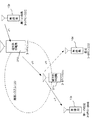
図7に示す通信システムは、後述する図2に示す通信システム100を、理解を容易にするために簡略化して示す模式図である。 The communication system shown in FIG. 7 is a schematic diagram showing the communication system 100 shown in FIG. 2 described later in a simplified manner for easy understanding.
また、図7に示すように、自局155には、コールサインとして「ZZZ」が割り当てられ、第一の他の無線局151には、コールサインとして「BBB」が割り当てられ、第二の他の無線局152には、コールサインとして「CCC」が割り当てられている。また、第一の端末系中継局311には、コールサイン「bbb」が、第二の端末系中継局312には、コールサイン「ccc」が割り当てられている。なお、これら3つの無線局151,152,155、及び2つの端末系中継局311と312は1つのゾーン(図2参照)内に配置されている。
Further, as shown in FIG. 7, the
図7に示すように、第二の他の無線局152が、第一の他の無線局151宛に信号J1を送信しているとする。この信号J1は、第二の端末系中継局312により中継され、第一の端末系中継局311から送信され、第一の他の無線局151により受信される。また、受信チャネルがダウンリンク用のチャネルに設定されている自局155もこの信号J1を受信する。
As shown in FIG. 7, a two-second
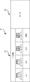
図8(a)に示すように、信号J1の通信フレームのヘッダ部には、送信先レピータコールサイン「bbb」と、送信元レピータコールサイン「ccc」と、送信先無線局コールサイン「BBB」と、送信元無線局コールサイン「CCC」とが挿入されている。 As shown in FIG. 8A, in the header portion of the communication frame of the signal J1, the transmission destination repeater call sign “bbb”, the transmission source repeater call sign “ccc”, and the transmission destination radio station call sign “BBB”. And a source radio station call sign “CCC” is inserted.
第一の端末系中継局311から送信された無線信号は、自局155でも受信される。
ここで、ユーザの操作により、受信部4の受信チャネルとしてダウンリンク周波数が設定されていれば、この通信フレームFは、自局155のコントローラ6にも提供される。
コントローラ6は、受信部4が何らかの信号(データ)を受信したことを検出すると、RAM6cのコールサイン記憶領域に受信データを記憶する。
Wireless signal transmitted from the first terminal repeater station 31 1 is received also own 15 5.
Here, the operation of the user, if it is set down link frequency as the reception channel of the receiving unit 4, the communication frame F is provided to the controller 6 of the
When the controller 6 detects that the receiving unit 4 has received some signal (data), the controller 6 stores the received data in the call sign storage area of the RAM 6c.
コントローラ6は、記憶した受信データ中のヘッダ情報Hから、送信元レピータコールサイン「ccc」と送信元無線局コールサイン「CCC」とを図8(b)に示すように抽出する。また、コントローラ6は、記憶した受信データ中のヘッダ情報Hから、レピータが制御に使用しているフラグを抽出し、コールサインを選定する際の判定に用いる。 The controller 6 extracts the source repeater call sign “ccc” and the source radio station call sign “CCC” from the header information H in the stored received data as shown in FIG. Further, the controller 6 extracts a flag used by the repeater for control from the header information H in the stored received data, and uses it for determination when selecting a call sign.
一方で、受信信号の音声データは、スピーカ9から放音され、無線機16のユーザは、自己宛の通信ではないが、その内容を聞くことができる。例えば、他の無線局からの不特定局呼出であるCQ等も放音される。ユーザが、CQに応答する場合や、交信内容から、今回の受信した(している)信号の送信局(送信者(発話者))と交信したいと思ったような場合には、ユーザは、コールサイン設定ボタン10aを押下(タッチ、クリック)する。
On the other hand, the audio data of the received signal is emitted from the
コールサイン設定ボタン10aが押下されると、コントローラ6は、抽出したコールサインを用いて、通信フレームFを生成する。即ち、図8(c)に示すように、判定に応じて最新又は1つ前に抽出した送信元レピータコールサイン「ccc」を送信先レピータコールサインとし、送信先無線局コールサイン「CCC」を送信先無線局コールサインとし、自局155が属す第一の端末系中継局311のコールサイン「bbb」を送信元レピータコールサインとし、自局155のコールサイン「ZZZ」を送信元無線局コールサインとして、ヘッダ部Hを生成する。
When the call
続いて、ユーザは、操作部10を操作すること等により、適宜のタイミングでこの通信フレームFを送信する。以後、データ部Dとして音声フレームとデータフレーム(同期データ)とを繰り返した通常の送信を行う。
Subsequently, the user transmits the communication frame F at an appropriate timing by operating the
また、コントローラ6は、記憶した受信データ中のヘッダ情報Hから、送信先レピータコールサイン「bbb」と送信先無線局コールサイン「BBB」とを抽出し、コールサイン設定ボタン10aが押下されると、抽出したコールサインを用いて、上述と同様の手順で、図8(d)に示すように、通信フレームFを生成する。ユーザは、適宜のタイミングでこの通信フレームFを送信し、以後、データ部Dとして音声フレームとデータフレーム(同期データ)とを繰り返した通常の送信を行う。
Further, the controller 6 extracts the transmission destination repeater call sign “bbb” and the transmission destination radio station call sign “BBB” from the header information H in the stored reception data, and when the call
次に、本実施の形態に係る無線機16が使用されるインフラとしての通信システム100について図2を参照して説明する。
Next, a communication system 100 as an infrastructure in which the
この通信システム100は、図示するように、複数のゾーンネットワーク(内部ネットワーク)20(20A,20B,...)がインターネットINに接続された構成を有する。 As shown in the figure, this communication system 100 has a configuration in which a plurality of zone networks (internal networks) 20 (20 A , 20 B ,...) Are connected to the Internet IN.
各ゾーンネットワーク20は、それぞれ、1又は複数のエリアネットワーク21(211,212,...)から構成される。
各エリアネットワーク21は、端末系中継局31(311,312,313,314,...)と、幹線系中継局32(321,322,323,324,...)と、該端末系中継局31に接続された複数の無線局15と、から構成されている。
Each zone network 20 includes one or more area networks 21 (21 1 , 21 2 ,...).
Each area network 21 includes a terminal relay station 31 (31 1 , 31 2 , 31 3 , 31 4 ,...) And a trunk relay station 32 (32 1 , 32 2 , 32 3 , 32 4 ,. .) And a plurality of
各ゾーンネットワーク20(20A,20B,...)におけるいずれかのエリアネットワーク21(211,212,...)の端末系中継局31(312,313,...)は、ゲートウエイ(GW)41(41A,41B,...)を介してインターネットINに接続されている。 Terminal relay stations 31 (31 2 , 31 3 ,...) Of any area network 21 (21 1 , 21 2 ,...) In each zone network 20 (20 A , 20 B, ...). Are connected to the Internet IN via gateways (GW) 41 (41 A , 41 B, ...).
また、同一のゾーンネットワーク20に属す各エリアネットワーク21の幹線系中継局32(321と322,323と324,...)は幹線MLを介して相互に接続されている。 Further, the trunk system relay stations 32 (32 1 and 32 2 , 32 3 and 32 4 ,...) Of each area network 21 belonging to the same zone network 20 are connected to each other via the trunk line ML.
各無線局15は、その無線局15が存在するエリアをカバーする端末系中継局31に、無線により接続されている。なお、無線局15は、無線機16を含む無線設備とその設備の運用者との総体を意味し、各無線局15には、識別情報としてのコールサインが付与されている。
Each
端末系中継局31は、同一のエリアネットワーク21内の無線局15とコールサインを用いた無線通信により通信を行う。また、同一ゾーンネットワーク20の他のエリアネットワーク21との通信のために幹線系中継局32との間で無線又は有線による通信を行う。
The terminal relay station 31 communicates with the
1つのゾーンネットワーク20に属す端末系中継局31のうち、1台(312と313)はそのゾーンネットワーク20とインターネットINとを接続するためのゾーンレピータとして機能する。ゾーンレピータ31は、GW41を介してインターネットINに接続され、ゾーンネットワーク20の外部宛の通信フレームをパケット化して、GW41を介してインターネットINに送出する。また、インターネットINから該ゾーンネットワーク20へのパケットをGW41を介して受信して、通信フレームを再構築し、自エリアネットワーク21宛ならば無線送信し、他エリアネットワーク21宛ならば幹線系中継局32に転送する。 Of the terminal relay stations 31 belonging to one zone network 20, one (31 2 and 31 3 ) functions as a zone repeater for connecting the zone network 20 and the Internet IN. The zone repeater 31 is connected to the Internet IN via the GW 41, packetizes a communication frame addressed to the outside of the zone network 20, and sends the packet to the Internet IN via the GW 41. In addition, a packet from the Internet IN to the zone network 20 is received via the GW 41 to reconstruct a communication frame. If it is addressed to the own area network 21, it is wirelessly transmitted. 32.
幹線系中継局32は、端末系中継局31に接続され、同一ゾーンネットワーク20内の他のエリアネットワーク21の幹線系中継局32と双方向通信を行って、データの送受信を行う。 The trunk relay station 32 is connected to the terminal relay station 31 and performs bidirectional communication with the trunk relay station 32 of another area network 21 in the same zone network 20 to transmit and receive data.
GW41(41A,41B)は、インターネットINと各ゾーンネットワーク20とを接続するためのものであり、コールサインとグローバルIPアドレスとが付与されている。GW41に付与するコールサインは、この実施の形態では、そのGW41が接続されている端末系中継局31のコールサイン(例えば、ccc、ddd)の末尾に「G」を加えたもの(例えば、cccG、dddG)とする。また、グローバルIPアドレスは、各GW41のインターネットIN上の固有のアドレスである。なお、端末系中継局31がGW41を兼務するようにしてもよい。 The GW 41 (41 A, 41 B ) is for connecting the Internet IN and each zone network 20, and is assigned a call sign and a global IP address. In this embodiment, the call sign assigned to the GW 41 is obtained by adding “G” to the end of the call sign (for example, ccc, ddd) of the terminal relay station 31 to which the GW 41 is connected (for example, cccG , DddG). The global IP address is a unique address on the Internet IN of each GW 41. The terminal relay station 31 may also serve as the GW 41.
また、インターネットIN上には管理サーバ51が設置されている。管理サーバ51には、通信システム100内の無線局15がどのゾーン、エリアに属しているかといった情報が格納されたテーブルを有しており、このテーブルに登録された情報を利用することによって後述するインターネットINを介してのゾーン間通信を確立する。
A management server 51 is installed on the Internet IN. The management server 51 has a table storing information such as which zone and area the
次に、このような構成の通信システム100における通信方法について説明する。
無線局15は、図3に示す基本構成を有する通信フレームFを生成して、これを送信する。この通信フレームFは、先頭のヘッダ部Hとこれに続くデータ部Dとから構成される。ヘッダ部Hは、相手方となる他の無線局15と接続するために使用される部分であり、他の無線局15との通信を確立するための情報信号を含んでいる。
Next, a communication method in the communication system 100 having such a configuration will be described.
The
ヘッダ部Hに含まれるビット同期は、入力信号の同期を取るためのビット同期信号である。ヘッダ部Hに含まれるフレーム同期は、これより信号であることを表すフレーム同期信号である。この信号の直後に前述したフラグが存在する。
ヘッダ部Hの識別情報(コールサイン)には、通信フレームFの送信先、送信元、中継ルート上の中継局を特定する識別情報が設定される。このヘッダ部Hの識別情報には、通信フレームFの送信先、送信元、中継ルート上の始点と終点の中継局のコールサインが設定される。
The bit synchronization included in the header portion H is a bit synchronization signal for synchronizing the input signal. The frame synchronization included in the header portion H is a frame synchronization signal that represents a signal. Immediately following this signal is the flag described above.
In the identification information (call sign) of the header portion H, identification information for specifying the transmission destination of the communication frame F, the transmission source, and the relay station on the relay route is set. In the identification information of the header portion H, the transmission destination of the communication frame F, the transmission source, and the call sign of the start and end relay stations on the relay route are set.
具体的には、識別情報には、送信先レピータコールサインと、送信元レピータコールサインと、送信先無線局コールサインと、送信元無線局コールサインとが設定される。送信先レピータコールサインは、送信先となる他の無線局15を管轄する端末系中継局31のコールサインである。なお、他ゾーンと通信する場合には、自ゾーンのGW41のコールサインを送信先レピータコールサインとして設定する。送信元レピータコールサインは、送信元となる自無線局15を管轄する端末系中継局31のコールサインである。また、送信先無線局コールサインは、送信先となる無線局15のコールサインである。送信元無線局コールサインは、自局のコールサインである。
Specifically, a transmission destination repeater call sign, a transmission source repeater call sign, a transmission destination wireless station call sign, and a transmission source wireless station call sign are set in the identification information. The transmission destination repeater call sign is a call sign of the terminal relay station 31 that has jurisdiction over another
ヘッダ部HのP_FCSは、ヘッダ部Hが有効かどうかのフレームチェックシーケンスを表す。 P_FCS of the header part H represents a frame check sequence as to whether the header part H is valid.
フレームFのデータ部Dには、音声フレームとデータフレームとが交互に繰り返して配置されて構成される。音声フレームは、音声通信用の音声信号が挿入されるフレームである。データフレームは、データ通信用の同期信号が挿入される。1つの通話が終わるまで、音声フレームとデータフレームが繰り返される。 In the data portion D of the frame F, audio frames and data frames are alternately and repeatedly arranged. The audio frame is a frame into which an audio signal for audio communication is inserted. In the data frame, a synchronization signal for data communication is inserted. The voice frame and the data frame are repeated until one call ends.
無線局15は、生成した通信フレームFを、無線で送信する。この通信フレームFは、同一エリアのエリアネットワーク21の端末系中継局31に受信される。
The
端末系中継局31は、ヘッダ部Hの相手先レピータコールサインが自己のコールサインであれば、それを無線で再送信し、他の端末系中継局31のコールサインであれば、幹線系中継局32に転送して幹線MLに送出する。 If the other party repeater call sign of the header part H is its own call sign, the terminal relay station 31 retransmits it wirelessly, and if it is the call sign of another terminal relay station 31, the trunk relay The data is transferred to the station 32 and sent to the trunk line ML.
通信フレームFの最終転送先が同一のゾーンネットワーク20内の場合、通信フレームFは該当する端末系中継局31に転送され、さらに、無線局15に無線送信される。
When the final transfer destination of the communication frame F is in the same zone network 20, the communication frame F is transferred to the corresponding terminal relay station 31 and further wirelessly transmitted to the
一方、通信フレームFの最終転送先が他のゾーンネットワーク20の場合、通信フレームFはヘッダ部Hの送信先レピータコールサインに従って、送信元である自局の属するゾーンのGW41に到達する。
ここで、送信元である自局の属するゾーンのGW41はインターネットIN上に設置された管理サーバ51に対して、通信フレームFの最終転送先である送信先無線局15に関する情報を問い合わせる。問い合わせを受けた管理サーバ51は、管理サーバ51が有しているテーブルに登録された情報に基づいて、最終転送先である送信先無線局15が属するゾーンのGW41の情報を、問い合わせ元のGW41に返信する。管理サーバ51からの返信を受け取った問い合わせ元のGW41は、通信フレームFから必要な情報を取り出し、管理サーバ51から受け取った情報に基づいて、送信先の無線局15が所属するゾーンのGW41のIPアドレスを宛先IPアドレス、自己のIPアドレスを送信元IPアドレスとするIPヘッダを付してIPパケット化して、インターネットIN上に出力する。
宛先GW41は、このIPパケットを受信し、元の通信フレームFを再生して、自ゾーンネットワーク20内の幹線MLに送出する。以後の動作は同様である。
On the other hand, when the final transfer destination of the communication frame F is another zone network 20, the communication frame F reaches the GW 41 of the zone to which the own station as the transmission source belongs according to the transmission destination repeater call sign of the header part H.
Here, the GW 41 in the zone to which the own station that is the transmission source inquires of the management server 51 installed on the Internet IN about information related to the transmission
The destination GW 41 receives this IP packet, reproduces the original communication frame F, and sends it to the trunk line ML in the own zone network 20. The subsequent operation is the same.
以上の通信動作を、具体例に基づいて説明する。 The above communication operation will be described based on a specific example.
1)エリア1の無線局151がエリア4の無線局154に通信する動作。
ユーザは、a)送信先レピータコールサインとして、自ゾーン内のGW41AのコールサインであるcccG、b)送信元レピータコールサインとしてエリア1の端末系中継局311のコールサインbbb、c)送信先無線局コールサインとして送信先無線局154のコールサインであるAAA、d)送信元無線局コールサインとして自局の無線局151のコールサインBBBを入力する。
1) An operation in which the
User, a) as the destination repeater call sign, a call sign of the GW 41 A in its own zone cccG, b) the source repeater call sign as an
無線局151は、図4(a)に示すような、ヘッダ部Hを備える通信フレームFを生成して、端末系中継局311に送信する。
端末系中継局311は、この通信フレームFを受信し、ヘッダ部Hに含まれる送信先レピータコールサイン(cccG)より、これを幹線系中継局321を介して幹線MLに送出する。 The terminal relay station 31 1 receives this communication frame F, and transmits it to the trunk line ML via the trunk relay station 32 1 from the transmission destination repeater call sign (cccG) included in the header portion H.
この通信フレームFは、幹線ML上を転送され、相手先レピータコールサインにより、GW41Aに到達する。 This communication frame F is transferred on the trunk line ML, and reaches the GW 41 A by the counterpart repeater call sign.
GW41Aは、管理サーバ51に対して無線局15に関する情報を問い合わせ、管理サーバ51からの問い合わせ結果に基づいて、図4(b)に示すように、通信フレームFの送信先レピータコールサインを、最終送信先のエリア4の端末系中継局314のコールサインaaaに変更し、送信元レピータコールサインを、送信先のゾーンBのGW41BのコールサインdddGに書き換える。
さらに、修正した通信フレームをパケット化し、送信先IPアドレスとして、GW41BのグローバルIPアドレス(222.15.10.6)、送信元IPアドレスとして、GW41AのグローバルIPアドレス(12.34.56.78)を含むIPヘッダを付して、図4(c)のIPパケットを生成し、インターネットIN上に出力する。
The GW 41 A inquires of the management server 51 about the information about the
Furthermore, packetizes the modified communication frame as the destination IP address, the global IP address of GW41 B (222.15.10.6), as the source IP address, the global IP address of GW41 A (12.34.56 .78) is added, and the IP packet of FIG. 4C is generated and output on the Internet IN.
このIPパケットは、インターネットIN上を転送され、ゾーンBのGW41Bに受信される。 This IP packet is transferred over the Internet IN, it is received by the GW 41 B zone B.
GW41Bは、IPヘッダを除去し、図4(b)に示す通信パケットを再生し、これをゾーンレピータ313を介して、ゾーンBの幹線MLに出力する。この通信フレームFは、幹線ML上を転送され、端末系中継局314に至り、無線送信される。 GW 41 B removes the IP header to reproduce the communication packet shown in FIG. 4 (b), through a zone repeater 31 3 this, and outputs the main line ML of the zone B. This communication frame F is transferred over the main line ML, reaches the terminal repeater station 31 4 is wirelessly transmitted.
無線局154は、受信した通信フレームFのヘッダ部Hの送信先無線局コールサインから自己宛であることを判別し、データ部Dを再生して、音声を再生する。
2)次に、同一ゾーン内のエリア1の無線局151から、エリア2の無線局152に送信する動作を説明する。
2) Next, from the
ユーザは、a)送信先レピータコールサインとして、端末系中継局312のコールサインであるccc、b)送信元レピータコールサインとしてエリア1の端末系中継局311のコールサインbbb、c)送信先無線局コールサインとして、無線局152のコールサインであるCCC、d)送信元無線局コールサインとして無線局151のコールサインBBBを入力する。
User, a) as the destination repeater call sign, a call sign terminal repeater station 31 2 ccc, b) transmission of the
無線局151は、図5に示すようなヘッダ部Hを備える通信フレームFを生成して、端末系中継局311に送信する。端末系中継局311は、ヘッダ部Hに含まれる送信先レピータコールサインより、これを幹線系中継局321を介して幹線MLに送出する。通信フレームFは、幹線MLを転送され、相手先レピータコールサインにより、端末系中継局312に到達する。端末系中継局312は、送信先レピータコールサインから、この通信フレームFを取り込み、無線送信する。無線局152は、送信された通信フレームFのヘッダ部Hに含まれる送信先無線局コールサインが自己のコールサインなので、これを受信し、受信した通信フレームFから音声を再生する。このようにして、ゾーンネットワーク20A内での通信が行われる。
3)次に、同一ゾーン内のエリア1の無線局151から、同一のエリア1の無線局155に送信する動作を説明する。
ユーザは、a)送信先レピータコールサインとして、端末系中継局311のコールサインであるbbb、b)送信元レピータコールサインとしてエリア1の端末系中継局311のコールサインbbb、c)送信先無線局のコールサインとして、無線局155のコールサインZZZ、d)送信元無線局コールサインとして無線局151のコールサインBBBを入力する。
3) Next, from the
User, a) as the destination repeater call sign, a call sign terminal repeater station 31 1 bbb, b) transmission of the
この入力に応答して、無線局151は、図6に例示するヘッダ部Hを備える通信フレームFを生成して、端末系中継局311に送信する。端末系中継局311は、ヘッダ部Hに含まれる相手先レピータコールサインより、この通信フレームFがエリア1用であると判別し、自エリアに無線送信する。
In response to this input, the
無線局155は、送信された通信フレームFのヘッダ部Hに含まれる送信先無線局コールサインが自己のコールサインなので、これを受信し、受信した通信フレームFから音声を再生する。このようにして、同一エリア内での通信が行われる。
以上に説明したように、この実施の形態の無線局15によれば、他の無線局からの不特定局呼出であるCQに即時応答を希望する場合や、他の無線局同士の音声通信を聞いて前記他の無線局のいずれかを相手局として交信を希望する場合などに、コールサイン設定ボタン10aを押下するというきわめて簡単な操作で、コールサインの入力や選択といった作業を必要とせずに、通信先を容易に特定して、迅速に通信を行うことができる。
As described above, according to the
なお、RAM6cの制御情報記憶領域には、受信した無線信号の制御情報(フラグ)をコールサイン設定ボタン10aの押下毎に受信順に記憶するようにし、コントローラ6は、最新に受信した無線信号のフラグにより無線信号がレピータからのものであると判断した後、念のために、次に新しい無線信号のフラグにより同様の判断を行うようにしてもよい。そして、そのフラグにより無線信号がレピータからのものであると判断した場合、さらに次に新しい無線信号のフラグにより同様の判断を行う。これにより、直近の無線局を送信元とする無線信号に含まれていた当該無線局の識別情報を、送信先の無線局の識別情報として挿入して通信フレームを生成する。
In the control information storage area of the RAM 6c, the control information (flag) of the received radio signal is stored in the order of reception every time the call
また、ユーザがコールサイン設定ボタン10aを押下するタイミングは任意であり、例えば、コールサイン設定ボタン10aが押下された際に、最も最近抽出したコールサインに基づいて通信フレームFを生成してもよい。この場合には、例えば、コールサインを抽出した際に、タイムスタンプを付しておき、これを参考にしてコールサインの新旧を判別する。或いは、ユーザがコールサイン設定ボタン10aが押下された際に、受信中の信号がある場合にのみ、その信号のヘッダ部に含まれているコールサインに基づいて通信フレームFを生成するようにしてもよい。
The timing at which the user presses the call
また、音声通信の場合にのみ、コールサインの抽出と通信フレームFのヘッダ部Hの生成を行うようにしてもよい。この場合、例えば、コールサイン設定ボタン10aが押下されたと判別した際に、通信内容がデータ通信であるか音声通信であるかを判別し、音声通信の場合に、送信フレームの生成を行うようにすればよい。
Further, only in the case of voice communication, the call sign may be extracted and the header portion H of the communication frame F may be generated. In this case, for example, when it is determined that the call
さらに、上記実施の形態では、コールサイン設定ボタン10aが押下される前に、コールサインの抽出を行ったが、コールサイン設定ボタン10aが押下されることを検出した後に、コールサインの抽出を行うようにしてもよい。
Further, in the above embodiment, the call sign is extracted before the call
上記実施の形態では、受信の対象をダウンリンクチャネルの一方としたが、アップリンクチャネル或いは両方を受信できるようにしてもよい。 In the above embodiment, the reception target is one of the downlink channels, but the uplink channel or both may be received.
また、ヘッダ情報Hを抽出した段階等で、例えば、図9に例示するように、「現在受信している(受信再生している)通信を行っている無線局と通信を行いますか?」などのメッセージを操作ボタン(アイコン等を含む)等と共にモニタ11に表示し、このメッセージに対する回答(ボタン操作、アイコン操作、マウス操作、パッド操作)等に応じて、通信フレームFを生成するようにしてもよい。
Further, at the stage where the header information H is extracted, for example, as illustrated in FIG. 9, “Do you want to communicate with the wireless station that is currently receiving (receiving and playing back) communication?” Are displayed on the
また、コールサインの設定をより容易にするため、上述のコールサイン自動設定機能に付加して、コントローラ6が抽出したコールサイン(コールサインの対)をRAM6cに蓄積してデータベース化し、さらに、図10に示すように、モニタ画面11aに表示したり、検索可能として、操作部10からの選択操作に応答して、コントローラ6が通信フレームFのヘッダ部Hに設定するようにしてもよい。
Further, in order to make the call sign setting easier, the call sign (call sign pair) extracted by the controller 6 is added to the above-mentioned call sign automatic setting function and stored in the RAM 6c to form a database. As shown in FIG. 10, the controller 6 may be set in the header portion H of the communication frame F in response to a selection operation from the
本実施の形態は、簡便な操作で、通信フレーム(特にヘッダ部H)を生成することを特徴とするものであり、コールサイン設定ボタン10aに対応する操作指示手段の構成は任意であり、ハードウエアでも、ソフトウエアでも、ボタンでも、アイコンでも、マウスでも、パッドでも、スイッチでも、キーでも、簡単なワンタッチ、ワンアクション的な動作で指示をできる構成ならば、その構成は任意である。
The present embodiment is characterized in that a communication frame (particularly the header portion H) is generated by a simple operation. The configuration of the operation instruction means corresponding to the call
アマチュア無線は、他アマチュア無線局同士の交信内容が受信・再生できることがデフォルトであり、本願発明は特に有効である。但し、本願発明は、これに限定されない。他者間の通信を受信して、受信情報からコールサインに相当するような識別情報を抽出してヘッダ部を生成可能ならば、様々な通信方式に適用可能である。また、上記実施の形態では、受信した通信フレーム中の送信元のコールサイン(識別情報)を抽出して送信相手として設定したが、受信した通信フレーム中の送信先のコールサイン(識別情報)を抽出して送信相手として設定して通信フレームを生成することも可能である。 For amateur radio, the default is that the contents of communication between other amateur radio stations can be received and reproduced, and the present invention is particularly effective. However, the present invention is not limited to this. If communication between others is received, identification information corresponding to a call sign is extracted from the received information, and a header part can be generated, the present invention can be applied to various communication methods. In the above embodiment, the call sign (identification information) of the transmission source in the received communication frame is extracted and set as the transmission partner, but the call sign (identification information) of the transmission destination in the received communication frame is set. It is also possible to extract and set as a transmission partner to generate a communication frame.
なお、図1に示すコントローラ6、送信部3、受信部4等をDSP(ディジタルシグナルプロセッサ)などを用いて構成してもよい。 Note that the controller 6, the transmission unit 3, the reception unit 4 and the like shown in FIG. 1 may be configured using a DSP (digital signal processor) or the like.
以上の説明では、無線局が信号を送受信するための信号の変調方式としてGMSK変調方式を採用する例により説明した。本発明を実施するにあたり、他の変調方式を採用することもできる。本発明を実施するにあたり、信号の変調方式として、QPSK変調方式やその他の変調方式を採用することもできる。 In the above description, the example in which the GMSK modulation method is adopted as the signal modulation method for the wireless station to transmit and receive signals has been described. In practicing the present invention, other modulation schemes can be employed. In practicing the present invention, a QPSK modulation method and other modulation methods may be employed as a signal modulation method.
1 アンテナ
2 送受信切替部
3 送信部
4 受信部
5 音声A/D・D/A変換部
6 コントローラ
6a CPU
6b ROM
6c RAM
7 増幅器
8 マイク
9 スピーカ
10 操作部
11 モニタ
11a モニタ画面
16 無線通信機(無線機)
DESCRIPTION OF
6b ROM
6c RAM
7
Claims (3)
前記受信手段が受信した無線局からの無線信号毎に、該無線局に関する識別情報を抽出する識別情報抽出手段と、
前記受信手段が受信した無線局からの無線信号及び中継局からの無線信号から、各無線信号毎に中継局による制御情報を抽出する制御情報抽出手段と、
前記抽出した各識別情報及び各制御情報を、抽出元である無線信号毎に少なくとも2以上保存する信号情報保存手段と、
ユーザによって操作可能で、操作されたことによって、通信フレームの生成を指示する操作手段と、
前記操作手段から通信フレーム作成の指示を受けると、前記信号情報保存手段に保存された各無線信号の制御情報から、無線局を送信元とする無線信号を判別し、無線局を送信元とすると判別された無線信号のうち最新の無線信号に含まれる識別情報を、送信先の無線局の識別情報として挿入して前記通信フレームを生成する通信フレーム生成手段と、
を備えたことを特徴とする通信機。 Radio signal received from the radio station including the identification information about the radio station and the control information by the relay station, and the control information by the relay station using the relay station as the source Receiving means for receiving a radio signal from a relay station including:
Identification information extracting means for extracting identification information about the wireless station for each wireless signal received by the receiving means;
Control information extracting means for extracting control information by the relay station for each radio signal from the radio signal from the radio station and the radio signal from the relay station received by the receiving means;
Signal information storage means for storing at least two or more of each of the extracted identification information and each control information for each radio signal that is an extraction source;
An operation means that can be operated by a user and instructs generation of a communication frame when operated,
When receiving an instruction to create a communication frame from the operation unit, a radio signal having a radio station as a transmission source is determined from control information of each radio signal stored in the signal information storage unit, and the radio station is a transmission source. Communication frame generation means for generating the communication frame by inserting identification information included in the latest wireless signal among the determined wireless signals as identification information of a transmission destination wireless station;
A communication device characterized by comprising:
前記通信フレーム生成手段は、ユーザの押操作に応答して、通信フレームを生成する、
ことを特徴とする請求項1に記載の通信機。 The operating means includes means for responding to a pressing operation,
The communication frame generation means generates a communication frame in response to a user's pressing operation.
The communication device according to claim 1.
無線局を送信元として中継局を介して受信される、該無線局に関する識別情報及び該中継局による制御情報を含む無線局からの無線信号と、中継局を送信元として該中継局による制御情報を含む中継局からの無線信号とを受信する受信ステップと、
前記受信手段が受信した無線局からの無線信号毎に、該無線局に関する識別情報を抽出する識別情報抽出ステップと、
前記受信ステップで受信した無線局からの無線信号及び中継局からの無線信号から、各無線信号毎に中継局による制御情報を抽出する制御情報抽出ステップと、
前記抽出した各識別情報及び各制御情報を、抽出元である無線信号毎に保存する信号情報保存ステップと、
前記信号情報保存ステップで保存された各無線信号の制御情報から、無線局を送信元とする無線信号を判別し、無線局を送信元とすると判別された無線信号のうち最新の無線信号に含まれる識別情報を、送信先の無線局の識別情報として挿入して前記通信フレームを生成する通信フレーム生成ステップと、
を実行させることを特徴とする通信制御プログラム。 On the computer,
Radio signal received from the radio station including the identification information about the radio station and the control information by the relay station, and the control information by the relay station using the relay station as the source Receiving a radio signal from a relay station including:
An identification information extracting step for extracting identification information about the radio station for each radio signal received from the radio station by the receiving means;
A control information extraction step for extracting control information by the relay station for each radio signal from the radio signal from the radio station and the radio signal from the relay station received in the reception step;
Signal information storing step for storing each extracted identification information and each control information for each radio signal that is an extraction source;
From the control information of each radio signal saved in the signal information saving step, the radio signal having the radio station as the transmission source is determined, and included in the latest radio signal among the radio signals determined to have the radio station as the transmission source A communication frame generating step of generating the communication frame by inserting identification information to be transmitted as identification information of a destination wireless station;
The communication control program characterized by performing this.
Priority Applications (1)
| Application Number | Priority Date | Filing Date | Title |
|---|---|---|---|
| JP2009033089A JP5099036B2 (en) | 2009-02-16 | 2009-02-16 | Communication device and communication control program |
Applications Claiming Priority (1)
| Application Number | Priority Date | Filing Date | Title |
|---|---|---|---|
| JP2009033089A JP5099036B2 (en) | 2009-02-16 | 2009-02-16 | Communication device and communication control program |
Publications (2)
| Publication Number | Publication Date |
|---|---|
| JP2010193009A true JP2010193009A (en) | 2010-09-02 |
| JP5099036B2 JP5099036B2 (en) | 2012-12-12 |
Family
ID=42818612
Family Applications (1)
| Application Number | Title | Priority Date | Filing Date |
|---|---|---|---|
| JP2009033089A Active JP5099036B2 (en) | 2009-02-16 | 2009-02-16 | Communication device and communication control program |
Country Status (1)
| Country | Link |
|---|---|
| JP (1) | JP5099036B2 (en) |
Citations (6)
| Publication number | Priority date | Publication date | Assignee | Title |
|---|---|---|---|---|
| JPH0522219A (en) * | 1991-07-10 | 1993-01-29 | Yaesu Musen Co Ltd | Radio communication system |
| JPH1062190A (en) * | 1996-08-21 | 1998-03-06 | Kenwood Corp | On-vehicle navigation system |
| JP2003152738A (en) * | 2001-11-16 | 2003-05-23 | Japan Amateur Radio League Inc | Network system, wireless terminal, and wireless relaying device |
| JP2006108823A (en) * | 2004-09-30 | 2006-04-20 | Icom Inc | Network system, gateway, and wireless terminal |
| JP2007043232A (en) * | 2005-07-29 | 2007-02-15 | Icom Inc | Communication terminal |
| JP2008301169A (en) * | 2007-05-31 | 2008-12-11 | Kenwood Corp | Radio device, control method, and program |
-
2009
- 2009-02-16 JP JP2009033089A patent/JP5099036B2/en active Active
Patent Citations (6)
| Publication number | Priority date | Publication date | Assignee | Title |
|---|---|---|---|---|
| JPH0522219A (en) * | 1991-07-10 | 1993-01-29 | Yaesu Musen Co Ltd | Radio communication system |
| JPH1062190A (en) * | 1996-08-21 | 1998-03-06 | Kenwood Corp | On-vehicle navigation system |
| JP2003152738A (en) * | 2001-11-16 | 2003-05-23 | Japan Amateur Radio League Inc | Network system, wireless terminal, and wireless relaying device |
| JP2006108823A (en) * | 2004-09-30 | 2006-04-20 | Icom Inc | Network system, gateway, and wireless terminal |
| JP2007043232A (en) * | 2005-07-29 | 2007-02-15 | Icom Inc | Communication terminal |
| JP2008301169A (en) * | 2007-05-31 | 2008-12-11 | Kenwood Corp | Radio device, control method, and program |
Also Published As
| Publication number | Publication date |
|---|---|
| JP5099036B2 (en) | 2012-12-12 |
Similar Documents
| Publication | Publication Date | Title |
|---|---|---|
| KR100966363B1 (en) | Relay unit, communication terminal and communication method | |
| JP4784384B2 (en) | Wireless communication system and automatic channel switching method | |
| JP4671798B2 (en) | Communication equipment | |
| JP5177006B2 (en) | Communication device and communication control program | |
| JP2007295135A (en) | Radio communication apparatus, repeater, and radio communication system | |
| JP5099036B2 (en) | Communication device and communication control program | |
| US20160269077A1 (en) | Relaying device and communication system | |
| US20060141928A1 (en) | Radio terminal, method for producing communication packet, and computer-readable recording medium | |
| JP6311456B2 (en) | transceiver | |
| JP2012015707A (en) | Radio device and computer program | |
| JP4562522B2 (en) | COMMUNICATION DEVICE AND COMMUNICATION METHOD | |
| JP4876933B2 (en) | Wireless communication system, control method therefor, and server | |
| KR20100004507A (en) | Communication terminal and method for performing video telephony | |
| JP4459035B2 (en) | Transmitter and method for generating communication frame | |
| JP5299149B2 (en) | Wireless communication apparatus and wireless communication system | |
| JP5699708B2 (en) | Call center user response support apparatus, program thereof, system thereof, and method of providing support | |
| JP5786527B2 (en) | Radio and computer program | |
| JP3645779B2 (en) | Data communication method, client, relay device, server, server / gateway, and recording medium recording the communication program | |
| JP6646239B2 (en) | Wireless communication system, wireless device, wireless communication method, method of generating packet, and method of reproducing data from packet | |
| JP4459034B2 (en) | COMMUNICATION DEVICE, COMMUNICATION SYSTEM, AND COMMUNICATION FRAME GENERATION METHOD | |
| JP6634172B1 (en) | Program and system for transmitting / receiving digital information (message) to / from a short-range communication network | |
| JP5120223B2 (en) | Remote repeater monitor system and remote repeater monitoring method | |
| JP2013098684A (en) | Wireless apparatus and computer program | |
| JP5721482B2 (en) | Satellite communication method, slave station and master station, satellite communication system | |
| JP2015156608A (en) | Terminal, call system, and call method |
Legal Events
| Date | Code | Title | Description |
|---|---|---|---|
| A621 | Written request for application examination |
Free format text: JAPANESE INTERMEDIATE CODE: A621 Effective date: 20110414 |
|
| TRDD | Decision of grant or rejection written | ||
| A01 | Written decision to grant a patent or to grant a registration (utility model) |
Free format text: JAPANESE INTERMEDIATE CODE: A01 Effective date: 20120828 |
|
| A01 | Written decision to grant a patent or to grant a registration (utility model) |
Free format text: JAPANESE INTERMEDIATE CODE: A01 |
|
| A61 | First payment of annual fees (during grant procedure) |
Free format text: JAPANESE INTERMEDIATE CODE: A61 Effective date: 20120910 |
|
| FPAY | Renewal fee payment (event date is renewal date of database) |
Free format text: PAYMENT UNTIL: 20151005 Year of fee payment: 3 |
|
| R150 | Certificate of patent or registration of utility model |
Ref document number: 5099036 Country of ref document: JP Free format text: JAPANESE INTERMEDIATE CODE: R150 Free format text: JAPANESE INTERMEDIATE CODE: R150 |
|
| FPAY | Renewal fee payment (event date is renewal date of database) |
Free format text: PAYMENT UNTIL: 20151005 Year of fee payment: 3 |
|
| R250 | Receipt of annual fees |
Free format text: JAPANESE INTERMEDIATE CODE: R250 |
|
| R250 | Receipt of annual fees |
Free format text: JAPANESE INTERMEDIATE CODE: R250 |
|
| R250 | Receipt of annual fees |
Free format text: JAPANESE INTERMEDIATE CODE: R250 |
|
| R250 | Receipt of annual fees |
Free format text: JAPANESE INTERMEDIATE CODE: R250 |
|
| R250 | Receipt of annual fees |
Free format text: JAPANESE INTERMEDIATE CODE: R250 |
|
| R250 | Receipt of annual fees |
Free format text: JAPANESE INTERMEDIATE CODE: R250 |
|
| R250 | Receipt of annual fees |
Free format text: JAPANESE INTERMEDIATE CODE: R250 |
|
| R250 | Receipt of annual fees |
Free format text: JAPANESE INTERMEDIATE CODE: R250 |
|
| R250 | Receipt of annual fees |
Free format text: JAPANESE INTERMEDIATE CODE: R250 |