JP2010188198A - Expandable guide sheath and apparatus and method using the same - Google Patents
Expandable guide sheath and apparatus and method using the same Download PDFInfo
- Publication number
- JP2010188198A JP2010188198A JP2010132478A JP2010132478A JP2010188198A JP 2010188198 A JP2010188198 A JP 2010188198A JP 2010132478 A JP2010132478 A JP 2010132478A JP 2010132478 A JP2010132478 A JP 2010132478A JP 2010188198 A JP2010188198 A JP 2010188198A
- Authority
- JP
- Japan
- Prior art keywords
- sheath
- lumen
- reinforcing member
- distal end
- proximal
- Prior art date
- Legal status (The legal status is an assumption and is not a legal conclusion. Google has not performed a legal analysis and makes no representation as to the accuracy of the status listed.)
- Granted
Links
- 238000000034 method Methods 0.000 title abstract description 47
- 230000003014 reinforcing effect Effects 0.000 claims description 143
- 230000002787 reinforcement Effects 0.000 claims description 27
- 238000003780 insertion Methods 0.000 claims description 16
- 230000037431 insertion Effects 0.000 claims description 16
- 239000011248 coating agent Substances 0.000 claims description 4
- 238000000576 coating method Methods 0.000 claims description 4
- 239000012530 fluid Substances 0.000 abstract description 24
- 210000005166 vasculature Anatomy 0.000 abstract description 24
- 210000003484 anatomy Anatomy 0.000 abstract description 7
- 239000000463 material Substances 0.000 description 37
- 210000004204 blood vessel Anatomy 0.000 description 32
- 210000003462 vein Anatomy 0.000 description 30
- 208000031481 Pathologic Constriction Diseases 0.000 description 16
- 238000003384 imaging method Methods 0.000 description 16
- 230000036262 stenosis Effects 0.000 description 16
- 208000037804 stenosis Diseases 0.000 description 16
- 239000000853 adhesive Substances 0.000 description 8
- 230000001070 adhesive effect Effects 0.000 description 8
- 210000001072 colon Anatomy 0.000 description 8
- 238000004891 communication Methods 0.000 description 8
- 229940079593 drug Drugs 0.000 description 7
- 239000003814 drug Substances 0.000 description 7
- 238000000926 separation method Methods 0.000 description 7
- 239000002872 contrast media Substances 0.000 description 6
- 239000013013 elastic material Substances 0.000 description 6
- 238000002405 diagnostic procedure Methods 0.000 description 5
- 239000012528 membrane Substances 0.000 description 5
- 229920000642 polymer Polymers 0.000 description 5
- 238000002560 therapeutic procedure Methods 0.000 description 5
- CURLTUGMZLYLDI-UHFFFAOYSA-N Carbon dioxide Chemical compound O=C=O CURLTUGMZLYLDI-UHFFFAOYSA-N 0.000 description 4
- RRHGJUQNOFWUDK-UHFFFAOYSA-N Isoprene Chemical compound CC(=C)C=C RRHGJUQNOFWUDK-UHFFFAOYSA-N 0.000 description 4
- 210000001035 gastrointestinal tract Anatomy 0.000 description 4
- 210000004324 lymphatic system Anatomy 0.000 description 4
- 239000002184 metal Substances 0.000 description 4
- 230000002093 peripheral effect Effects 0.000 description 4
- 210000002345 respiratory system Anatomy 0.000 description 4
- 230000002792 vascular Effects 0.000 description 4
- JOYRKODLDBILNP-UHFFFAOYSA-N Ethyl urethane Chemical compound CCOC(N)=O JOYRKODLDBILNP-UHFFFAOYSA-N 0.000 description 3
- 239000004812 Fluorinated ethylene propylene Substances 0.000 description 3
- 239000004698 Polyethylene Substances 0.000 description 3
- FAPWRFPIFSIZLT-UHFFFAOYSA-M Sodium chloride Chemical compound [Na+].[Cl-] FAPWRFPIFSIZLT-UHFFFAOYSA-M 0.000 description 3
- 238000013019 agitation Methods 0.000 description 3
- 239000003146 anticoagulant agent Substances 0.000 description 3
- 229960004676 antithrombotic agent Drugs 0.000 description 3
- 239000002131 composite material Substances 0.000 description 3
- 230000008602 contraction Effects 0.000 description 3
- 238000002224 dissection Methods 0.000 description 3
- 230000003073 embolic effect Effects 0.000 description 3
- 229920000295 expanded polytetrafluoroethylene Polymers 0.000 description 3
- 238000002594 fluoroscopy Methods 0.000 description 3
- 238000002608 intravascular ultrasound Methods 0.000 description 3
- 229920009441 perflouroethylene propylene Polymers 0.000 description 3
- 239000004033 plastic Substances 0.000 description 3
- 229920003023 plastic Polymers 0.000 description 3
- 229920000573 polyethylene Polymers 0.000 description 3
- 229920000139 polyethylene terephthalate Polymers 0.000 description 3
- 239000005020 polyethylene terephthalate Substances 0.000 description 3
- 229920001296 polysiloxane Polymers 0.000 description 3
- -1 polytetrafluoroethylene Polymers 0.000 description 3
- 229920001343 polytetrafluoroethylene Polymers 0.000 description 3
- 239000004810 polytetrafluoroethylene Substances 0.000 description 3
- 239000011780 sodium chloride Substances 0.000 description 3
- 238000013151 thrombectomy Methods 0.000 description 3
- 238000002604 ultrasonography Methods 0.000 description 3
- 238000002679 ablation Methods 0.000 description 2
- 150000001336 alkenes Chemical class 0.000 description 2
- 238000002399 angioplasty Methods 0.000 description 2
- 210000001367 artery Anatomy 0.000 description 2
- 238000005452 bending Methods 0.000 description 2
- 229910002092 carbon dioxide Inorganic materials 0.000 description 2
- 239000001569 carbon dioxide Substances 0.000 description 2
- 230000000747 cardiac effect Effects 0.000 description 2
- 239000003795 chemical substances by application Substances 0.000 description 2
- 238000007796 conventional method Methods 0.000 description 2
- 238000002788 crimping Methods 0.000 description 2
- 238000005520 cutting process Methods 0.000 description 2
- 238000005516 engineering process Methods 0.000 description 2
- 238000001125 extrusion Methods 0.000 description 2
- 239000011521 glass Substances 0.000 description 2
- 238000001802 infusion Methods 0.000 description 2
- 239000004816 latex Substances 0.000 description 2
- 229920000126 latex Polymers 0.000 description 2
- 210000005240 left ventricle Anatomy 0.000 description 2
- 238000002595 magnetic resonance imaging Methods 0.000 description 2
- 238000013507 mapping Methods 0.000 description 2
- 238000002483 medication Methods 0.000 description 2
- 238000012986 modification Methods 0.000 description 2
- 230000004048 modification Effects 0.000 description 2
- JRZJOMJEPLMPRA-UHFFFAOYSA-N olefin Natural products CCCCCCCC=C JRZJOMJEPLMPRA-UHFFFAOYSA-N 0.000 description 2
- 230000010412 perfusion Effects 0.000 description 2
- 230000001225 therapeutic effect Effects 0.000 description 2
- 208000005189 Embolism Diseases 0.000 description 1
- CZMRCDWAGMRECN-UGDNZRGBSA-N Sucrose Chemical compound O[C@H]1[C@H](O)[C@@H](CO)O[C@@]1(CO)O[C@@H]1[C@H](O)[C@@H](O)[C@H](O)[C@@H](CO)O1 CZMRCDWAGMRECN-UGDNZRGBSA-N 0.000 description 1
- 229930006000 Sucrose Natural products 0.000 description 1
- 208000007536 Thrombosis Diseases 0.000 description 1
- 208000027418 Wounds and injury Diseases 0.000 description 1
- 230000009471 action Effects 0.000 description 1
- 239000002260 anti-inflammatory agent Substances 0.000 description 1
- 229940124599 anti-inflammatory drug Drugs 0.000 description 1
- 239000002473 artificial blood Substances 0.000 description 1
- QVGXLLKOCUKJST-UHFFFAOYSA-N atomic oxygen Chemical compound [O] QVGXLLKOCUKJST-UHFFFAOYSA-N 0.000 description 1
- 230000008901 benefit Effects 0.000 description 1
- 238000001574 biopsy Methods 0.000 description 1
- 230000015572 biosynthetic process Effects 0.000 description 1
- 210000001124 body fluid Anatomy 0.000 description 1
- 239000010839 body fluid Substances 0.000 description 1
- 239000002775 capsule Substances 0.000 description 1
- 210000004720 cerebrum Anatomy 0.000 description 1
- 230000008859 change Effects 0.000 description 1
- 210000003748 coronary sinus Anatomy 0.000 description 1
- 230000010102 embolization Effects 0.000 description 1
- 239000008393 encapsulating agent Substances 0.000 description 1
- HQQADJVZYDDRJT-UHFFFAOYSA-N ethene;prop-1-ene Chemical group C=C.CC=C HQQADJVZYDDRJT-UHFFFAOYSA-N 0.000 description 1
- 210000003191 femoral vein Anatomy 0.000 description 1
- 239000000835 fiber Substances 0.000 description 1
- 239000011888 foil Substances 0.000 description 1
- 230000002496 gastric effect Effects 0.000 description 1
- 230000002439 hemostatic effect Effects 0.000 description 1
- 238000002513 implantation Methods 0.000 description 1
- 238000002347 injection Methods 0.000 description 1
- 239000007924 injection Substances 0.000 description 1
- 208000014674 injury Diseases 0.000 description 1
- 239000007788 liquid Substances 0.000 description 1
- 239000000314 lubricant Substances 0.000 description 1
- 238000002324 minimally invasive surgery Methods 0.000 description 1
- 238000012544 monitoring process Methods 0.000 description 1
- 210000005036 nerve Anatomy 0.000 description 1
- HLXZNVUGXRDIFK-UHFFFAOYSA-N nickel titanium Chemical class [Ti].[Ti].[Ti].[Ti].[Ti].[Ti].[Ti].[Ti].[Ti].[Ti].[Ti].[Ni].[Ni].[Ni].[Ni].[Ni].[Ni].[Ni].[Ni].[Ni].[Ni].[Ni].[Ni].[Ni].[Ni] HLXZNVUGXRDIFK-UHFFFAOYSA-N 0.000 description 1
- 239000001301 oxygen Substances 0.000 description 1
- 229910052760 oxygen Inorganic materials 0.000 description 1
- 239000002861 polymer material Substances 0.000 description 1
- 238000003825 pressing Methods 0.000 description 1
- 230000002265 prevention Effects 0.000 description 1
- 230000002250 progressing effect Effects 0.000 description 1
- 230000000541 pulsatile effect Effects 0.000 description 1
- 230000005855 radiation Effects 0.000 description 1
- 210000005245 right atrium Anatomy 0.000 description 1
- 238000007790 scraping Methods 0.000 description 1
- 238000009958 sewing Methods 0.000 description 1
- 239000002356 single layer Substances 0.000 description 1
- 229910000679 solder Inorganic materials 0.000 description 1
- 239000007787 solid Substances 0.000 description 1
- 238000001228 spectrum Methods 0.000 description 1
- 230000000638 stimulation Effects 0.000 description 1
- 210000001321 subclavian vein Anatomy 0.000 description 1
- 239000005720 sucrose Substances 0.000 description 1
- 230000001629 suppression Effects 0.000 description 1
- 230000008733 trauma Effects 0.000 description 1
- 238000011144 upstream manufacturing Methods 0.000 description 1
- 238000012800 visualization Methods 0.000 description 1
- 238000003466 welding Methods 0.000 description 1
Images


Classifications
-
- A—HUMAN NECESSITIES
- A61—MEDICAL OR VETERINARY SCIENCE; HYGIENE
- A61M—DEVICES FOR INTRODUCING MEDIA INTO, OR ONTO, THE BODY; DEVICES FOR TRANSDUCING BODY MEDIA OR FOR TAKING MEDIA FROM THE BODY; DEVICES FOR PRODUCING OR ENDING SLEEP OR STUPOR
- A61M25/00—Catheters; Hollow probes
- A61M25/10—Balloon catheters
- A61M25/1027—Making of balloon catheters
-
- A—HUMAN NECESSITIES
- A61—MEDICAL OR VETERINARY SCIENCE; HYGIENE
- A61B—DIAGNOSIS; SURGERY; IDENTIFICATION
- A61B17/00—Surgical instruments, devices or methods
- A61B17/34—Trocars; Puncturing needles
- A61B17/3417—Details of tips or shafts, e.g. grooves, expandable, bendable; Multiple coaxial sliding cannulas, e.g. for dilating
- A61B17/3421—Cannulas
- A61B17/3431—Cannulas being collapsible, e.g. made of thin flexible material
-
- A—HUMAN NECESSITIES
- A61—MEDICAL OR VETERINARY SCIENCE; HYGIENE
- A61B—DIAGNOSIS; SURGERY; IDENTIFICATION
- A61B17/00—Surgical instruments, devices or methods
- A61B17/34—Trocars; Puncturing needles
- A61B17/3417—Details of tips or shafts, e.g. grooves, expandable, bendable; Multiple coaxial sliding cannulas, e.g. for dilating
- A61B17/3421—Cannulas
- A61B17/3439—Cannulas with means for changing the inner diameter of the cannula, e.g. expandable
-
- A—HUMAN NECESSITIES
- A61—MEDICAL OR VETERINARY SCIENCE; HYGIENE
- A61M—DEVICES FOR INTRODUCING MEDIA INTO, OR ONTO, THE BODY; DEVICES FOR TRANSDUCING BODY MEDIA OR FOR TAKING MEDIA FROM THE BODY; DEVICES FOR PRODUCING OR ENDING SLEEP OR STUPOR
- A61M25/00—Catheters; Hollow probes
- A61M25/01—Introducing, guiding, advancing, emplacing or holding catheters
- A61M25/06—Body-piercing guide needles or the like
- A61M25/0662—Guide tubes
-
- A—HUMAN NECESSITIES
- A61—MEDICAL OR VETERINARY SCIENCE; HYGIENE
- A61M—DEVICES FOR INTRODUCING MEDIA INTO, OR ONTO, THE BODY; DEVICES FOR TRANSDUCING BODY MEDIA OR FOR TAKING MEDIA FROM THE BODY; DEVICES FOR PRODUCING OR ENDING SLEEP OR STUPOR
- A61M25/00—Catheters; Hollow probes
- A61M25/10—Balloon catheters
- A61M25/1002—Balloon catheters characterised by balloon shape
-
- A—HUMAN NECESSITIES
- A61—MEDICAL OR VETERINARY SCIENCE; HYGIENE
- A61M—DEVICES FOR INTRODUCING MEDIA INTO, OR ONTO, THE BODY; DEVICES FOR TRANSDUCING BODY MEDIA OR FOR TAKING MEDIA FROM THE BODY; DEVICES FOR PRODUCING OR ENDING SLEEP OR STUPOR
- A61M25/00—Catheters; Hollow probes
- A61M25/10—Balloon catheters
- A61M25/104—Balloon catheters used for angioplasty
-
- A—HUMAN NECESSITIES
- A61—MEDICAL OR VETERINARY SCIENCE; HYGIENE
- A61F—FILTERS IMPLANTABLE INTO BLOOD VESSELS; PROSTHESES; DEVICES PROVIDING PATENCY TO, OR PREVENTING COLLAPSING OF, TUBULAR STRUCTURES OF THE BODY, e.g. STENTS; ORTHOPAEDIC, NURSING OR CONTRACEPTIVE DEVICES; FOMENTATION; TREATMENT OR PROTECTION OF EYES OR EARS; BANDAGES, DRESSINGS OR ABSORBENT PADS; FIRST-AID KITS
- A61F2/00—Filters implantable into blood vessels; Prostheses, i.e. artificial substitutes or replacements for parts of the body; Appliances for connecting them with the body; Devices providing patency to, or preventing collapsing of, tubular structures of the body, e.g. stents
- A61F2/01—Filters implantable into blood vessels
- A61F2/011—Instruments for their placement or removal
-
- A—HUMAN NECESSITIES
- A61—MEDICAL OR VETERINARY SCIENCE; HYGIENE
- A61F—FILTERS IMPLANTABLE INTO BLOOD VESSELS; PROSTHESES; DEVICES PROVIDING PATENCY TO, OR PREVENTING COLLAPSING OF, TUBULAR STRUCTURES OF THE BODY, e.g. STENTS; ORTHOPAEDIC, NURSING OR CONTRACEPTIVE DEVICES; FOMENTATION; TREATMENT OR PROTECTION OF EYES OR EARS; BANDAGES, DRESSINGS OR ABSORBENT PADS; FIRST-AID KITS
- A61F2/00—Filters implantable into blood vessels; Prostheses, i.e. artificial substitutes or replacements for parts of the body; Appliances for connecting them with the body; Devices providing patency to, or preventing collapsing of, tubular structures of the body, e.g. stents
- A61F2/95—Instruments specially adapted for placement or removal of stents or stent-grafts
- A61F2002/9505—Instruments specially adapted for placement or removal of stents or stent-grafts having retaining means other than an outer sleeve, e.g. male-female connector between stent and instrument
- A61F2002/9511—Instruments specially adapted for placement or removal of stents or stent-grafts having retaining means other than an outer sleeve, e.g. male-female connector between stent and instrument the retaining means being filaments or wires
-
- A—HUMAN NECESSITIES
- A61—MEDICAL OR VETERINARY SCIENCE; HYGIENE
- A61M—DEVICES FOR INTRODUCING MEDIA INTO, OR ONTO, THE BODY; DEVICES FOR TRANSDUCING BODY MEDIA OR FOR TAKING MEDIA FROM THE BODY; DEVICES FOR PRODUCING OR ENDING SLEEP OR STUPOR
- A61M25/00—Catheters; Hollow probes
- A61M25/01—Introducing, guiding, advancing, emplacing or holding catheters
- A61M2025/0177—Introducing, guiding, advancing, emplacing or holding catheters having external means for receiving guide wires, wires or stiffening members, e.g. loops, clamps or lateral tubes
-
- A—HUMAN NECESSITIES
- A61—MEDICAL OR VETERINARY SCIENCE; HYGIENE
- A61M—DEVICES FOR INTRODUCING MEDIA INTO, OR ONTO, THE BODY; DEVICES FOR TRANSDUCING BODY MEDIA OR FOR TAKING MEDIA FROM THE BODY; DEVICES FOR PRODUCING OR ENDING SLEEP OR STUPOR
- A61M25/00—Catheters; Hollow probes
- A61M25/01—Introducing, guiding, advancing, emplacing or holding catheters
- A61M25/06—Body-piercing guide needles or the like
- A61M25/0662—Guide tubes
- A61M2025/0681—Systems with catheter and outer tubing, e.g. sheath, sleeve or guide tube
-
- A—HUMAN NECESSITIES
- A61—MEDICAL OR VETERINARY SCIENCE; HYGIENE
- A61M—DEVICES FOR INTRODUCING MEDIA INTO, OR ONTO, THE BODY; DEVICES FOR TRANSDUCING BODY MEDIA OR FOR TAKING MEDIA FROM THE BODY; DEVICES FOR PRODUCING OR ENDING SLEEP OR STUPOR
- A61M25/00—Catheters; Hollow probes
- A61M25/10—Balloon catheters
- A61M25/1002—Balloon catheters characterised by balloon shape
- A61M2025/1004—Balloons with folds, e.g. folded or multifolded
-
- A—HUMAN NECESSITIES
- A61—MEDICAL OR VETERINARY SCIENCE; HYGIENE
- A61M—DEVICES FOR INTRODUCING MEDIA INTO, OR ONTO, THE BODY; DEVICES FOR TRANSDUCING BODY MEDIA OR FOR TAKING MEDIA FROM THE BODY; DEVICES FOR PRODUCING OR ENDING SLEEP OR STUPOR
- A61M25/00—Catheters; Hollow probes
- A61M25/10—Balloon catheters
- A61M2025/1043—Balloon catheters with special features or adapted for special applications
- A61M2025/1088—Balloon catheters with special features or adapted for special applications having special surface characteristics depending on material properties or added substances, e.g. for reducing friction
-
- A—HUMAN NECESSITIES
- A61—MEDICAL OR VETERINARY SCIENCE; HYGIENE
- A61M—DEVICES FOR INTRODUCING MEDIA INTO, OR ONTO, THE BODY; DEVICES FOR TRANSDUCING BODY MEDIA OR FOR TAKING MEDIA FROM THE BODY; DEVICES FOR PRODUCING OR ENDING SLEEP OR STUPOR
- A61M29/00—Dilators with or without means for introducing media, e.g. remedies
- A61M29/02—Dilators made of swellable material
- A61M2029/025—Dilators made of swellable material characterised by the guiding element
-
- A—HUMAN NECESSITIES
- A61—MEDICAL OR VETERINARY SCIENCE; HYGIENE
- A61M—DEVICES FOR INTRODUCING MEDIA INTO, OR ONTO, THE BODY; DEVICES FOR TRANSDUCING BODY MEDIA OR FOR TAKING MEDIA FROM THE BODY; DEVICES FOR PRODUCING OR ENDING SLEEP OR STUPOR
- A61M25/00—Catheters; Hollow probes
- A61M25/01—Introducing, guiding, advancing, emplacing or holding catheters
- A61M25/06—Body-piercing guide needles or the like
- A61M25/0662—Guide tubes
- A61M25/0668—Guide tubes splittable, tear apart
Landscapes
- Health & Medical Sciences (AREA)
- Life Sciences & Earth Sciences (AREA)
- Heart & Thoracic Surgery (AREA)
- Animal Behavior & Ethology (AREA)
- Veterinary Medicine (AREA)
- Public Health (AREA)
- Engineering & Computer Science (AREA)
- Biomedical Technology (AREA)
- General Health & Medical Sciences (AREA)
- Surgery (AREA)
- Biophysics (AREA)
- Pulmonology (AREA)
- Anesthesiology (AREA)
- Hematology (AREA)
- Child & Adolescent Psychology (AREA)
- Molecular Biology (AREA)
- Medical Informatics (AREA)
- Nuclear Medicine, Radiotherapy & Molecular Imaging (AREA)
- Pathology (AREA)
- Vascular Medicine (AREA)
- Oral & Maxillofacial Surgery (AREA)
- Cardiology (AREA)
- Transplantation (AREA)
- Media Introduction/Drainage Providing Device (AREA)
- Endoscopes (AREA)
- Materials For Medical Uses (AREA)
- Shaping By String And By Release Of Stress In Plastics And The Like (AREA)
- Catching Or Destruction (AREA)
- Prostheses (AREA)
Abstract
【課題】例えば、患者の脈管構造内の管である、体管腔にアクセスする、及び/又は体管腔(例えば患者の脈管構造内)に器具を運ぶための装置および方法を提供する。
【解決手段】収縮されている状態から、少なくとも部分的に内部で内腔を規定する拡張した状態にまで膨張できる可撓性を有するシースが提供される。シースは滑らかで比較的薄い壁を有し、それにより、曲がりくねったアナトミーを経由して及び/または比較的狭い通路中に、流体及び/又は器具を運ぶための折り畳み可能/膨張可能であるガイドを提供する。シースは、収縮した状態で、入口サイトから体管腔内に進行させられる。シースが目的とする体管腔に達すると、シースは拡張した状態に膨み、それによりシース内に内腔を規定し、流体および/または器具がシースの内腔を経由して体内に導入される。処理が終了すると、シースは体管腔から除去される。
【選択図】図2AAn apparatus and method for accessing a body lumen and / or carrying an instrument into a body lumen (eg, within a patient's vasculature), for example, a tube within the patient's vasculature. .
A flexible sheath is provided that can expand from a deflated state to an expanded state at least partially defining a lumen therein. The sheath has a smooth and relatively thin wall, thereby providing a foldable / expandable guide for carrying fluids and / or instruments via tortuous anatomy and / or into a relatively narrow passage. provide. The sheath is advanced from the entry site into the body lumen in a contracted state. When the sheath reaches the desired body lumen, the sheath swells into an expanded state, thereby defining a lumen within the sheath, and fluids and / or instruments are introduced into the body via the sheath lumen. The When processing is complete, the sheath is removed from the body lumen.
[Selection] Figure 2A
Description
本発明は、概して、器具および/または薬剤を医療的な処置の間に運ぶ装置および方法に関し、特に、体管腔にアクセスする及び/または患者の体管腔に器具を送るガイドシースに関する。 The present invention relates generally to devices and methods for delivering instruments and / or medications during medical procedures, and more particularly to guide sheaths for accessing and / or delivering instruments to a body lumen of a patient.
(背景技術)
最小限の侵襲性の処置が、種々の医療の場において、例えば、脈官介入(例えば、脈管形成術、ステント植込み術、塞栓の予防、心臓電気刺激、心臓写像および明視化等)のために実施されてきた。これらの処置は、概して、器具を患者の脈管構造内に正確に誘導し、配置することに依存する。
(Background technology)
Minimally invasive procedures can be used in various medical settings, for example, for vascular intervention (eg, angioplasty, stent implantation, embolism prevention, cardiac electrical stimulation, cardiac mapping and visualization) Has been implemented for. These procedures generally rely on the precise guidance and placement of the instrument within the patient's vasculature.
(背景技術)
そのような処置の間、ターゲット(または目的)とする管は、介在する脈管構造を経由して、ターゲットとする管に進行するガイドワイヤを用いてアクセスされ、それにより管に「線路」を与えることができる。1または複数の器具(例えば、カテーテル、シース等)がガイドワイヤまたは「レール」の上を進行して、管内に進行する。したがって、診断および/または治療処置は、これらの線路の上を1または複数の器具を進行させることにより実施され得る。
(Background technology)
During such a procedure, the target (or target) tube is accessed using a guidewire that travels through the intervening vasculature to the target tube, thereby “tracking” the tube. Can be given. One or more instruments (eg, catheters, sheaths, etc.) travel over the guidewire or “rail” and into the tube. Thus, diagnostic and / or therapeutic procedures can be performed by advancing one or more instruments over these tracks.
ガイドワイヤ上で器具を進行させることには、多くの危険が伴う。例えば、カテーテルまたは他の器具は、特に器具が狭い通路または曲がりくねったアナトミー(または解剖学的構造体)を進行するときに、鋭利な屈曲を生じて、管の壁を削り、あるいは損傷することがある。そのような器具はまた、塞栓物質を移動させる、あるいは管の壁に孔を開けるという危険をもたらす。 There are many dangers associated with advancing the instrument over the guidewire. For example, catheters or other instruments can cause sharp bends, scraping or damaging the walls of the tube, especially when the instrument travels through narrow passages or tortuous anatomy (or anatomical structures). is there. Such devices also pose a risk of moving the embolic material or puncturing the wall of the tube.
加えて、体の深いところにある非常に小さい管にアクセスすること(例えば、患者の心臓内に、例えば心室内のぺーシング・リードを冠静脈に配置すること)が望まれることがしばしばある。しかしながら、器具(例えば、ガイドシース、リード等)は、比較的大きい断面積を有することがあり、および/または、比較的鈍い遠位端部を有することがあり、そのことは、そのような器具が所望のように小さい管に深く進むことを困難にする。 In addition, it is often desirable to access very small tubes deep in the body (eg, placing a pacing lead in the heart of the patient, eg, in the coronary vein). However, instruments (eg, guide sheaths, leads, etc.) may have a relatively large cross-sectional area and / or have a relatively blunt distal end, which means that such instruments Makes it difficult to go as deep into a small tube as desired.
したがって、器具を血管内もしくは他の体管腔(またはボディ・ルーメン)内に器具を運ぶ、ならびに/または管もしくは他の体管腔にアクセスするための装置および方法が有用であろう。 Accordingly, devices and methods for carrying the instrument into a blood vessel or other body lumen (or body lumen) and / or accessing the tube or other body lumen would be useful.
(発明の概要)
本発明は、医療処置の間、体管腔にアクセスするための、ならびに/または体管腔に器具および/もしくは薬剤を運ぶための装置および方法を概して対象としている。より特には、本発明は、ガイドシース、および当該ガイドシースを使用して患者の体管腔内(例えば、患者の冠状、神経および/または末梢の脈管構造内、患者の胃腸管、尿生殖管、呼吸器管、リンパ管系、および/または外科的に形成された流路内)に器具および/または薬剤を運ぶことを容易ならしめる方法を対象とする。
(Summary of Invention)
The present invention is generally directed to devices and methods for accessing a body lumen and / or for delivering instruments and / or medications to a body lumen during a medical procedure. More particularly, the present invention relates to a guide sheath and the patient's body lumen using the guide sheath (eg, within the patient's coronary, nerve and / or peripheral vasculature, the patient's gastrointestinal tract, urogenital) The present invention is directed to a method for facilitating the delivery of instruments and / or drugs into a tube, respiratory tract, lymphatic system, and / or surgically formed flow path.
本発明の1つの要旨において、例えば、体管腔への挿入を許容するべく、シースの輪郭を最小にする収縮した状態から、シースが少なくとも部分的にその内部に内腔を規定する拡張した(または広がった、もしくは膨らんだ)状態に膨張可能な、長尺の膨張可能なシースを含むシース装置が提供される。シースは滑らかな材料、ポリマー、および/または弾性材料であって、好ましくは比較的薄い壁を有する材料で形成することができ、それにより、実質的に可撓性を有する及び/又は薄弱であり得る管状のシースを与える。例えば、シースは、約0.001〜1.25mmの間、好ましくは約0.005〜0.6mmの間にある壁厚を含んでよい。 In one aspect of the present invention, for example, from a contracted state that minimizes the contour of the sheath to allow insertion into a body lumen, the sheath is expanded to at least partially define a lumen therein (see FIG. A sheath device is provided that includes an elongate inflatable sheath that is inflatable to (or expanded or inflated). The sheath can be formed of a smooth material, a polymer, and / or an elastic material, preferably a material having a relatively thin wall, thereby being substantially flexible and / or weak. The resulting tubular sheath is provided. For example, the sheath may include a wall thickness that is between about 0.001 and 1.25 mm, preferably between about 0.005 and 0.6 mm.
必要に応じて、シースは、シースに沿って、例えば、同軸に、螺旋状に、および/またはシースの周囲に延在する1または複数の補強要素を含んでよい。そのような補強要素は搬送の間、シースを支持し得、および/または拡張した状態にて所望の形状および/または寸法をとるシースを補強し得る。加えて又はこれに代えて、補強または強化部材を、シースを支持する、あるいは担持するために設けて、収縮した状態にてそれを導入するのを容易にしてよい。必要に応じて、シースおよび/または補強部材は、抗血栓剤および/または親水性コーティングで被覆されてよい。 Optionally, the sheath may include one or more reinforcing elements that extend along the sheath, eg, coaxially, spirally, and / or around the sheath. Such reinforcing elements can support the sheath during delivery and / or reinforce the sheath in the expanded state and take the desired shape and / or dimensions. In addition or alternatively, a reinforcing or reinforcing member may be provided to support or carry the sheath to facilitate its introduction in a contracted state. If desired, the sheath and / or reinforcing member may be coated with an antithrombotic agent and / or a hydrophilic coating.
好ましくは、膨張可能なシースは、近位端部、遠位端部を含み、患者の体への入口サイトとターゲットとする体管腔との間で延在するのに十分な長さを有し、例えば、約2cm〜300cm、より好ましくは約20cm〜150cmの長さを有する。一つの形態において、シースは、管状部材であってよく、別の形態において、シースは、シート材料であって、シートと補強部材がともに内腔(またはルーメン)を規定するように、そのエッジが補強部材に取り付けられているシート材料を含んでよい。 Preferably, the inflatable sheath includes a proximal end, a distal end, and has a length sufficient to extend between the entrance site to the patient's body and the target body lumen. For example, it has a length of about 2 cm to 300 cm, more preferably about 20 cm to 150 cm. In one form, the sheath may be a tubular member, and in another form, the sheath is a sheet material whose edges are such that the sheet and the reinforcing member together define a lumen (or lumen). It may include a sheet material attached to the reinforcing member.
シースの遠位端部は、内腔を経由して挿入された器具が開口部から体管腔内に進行させられるように、内腔と連絡している開口部を含んでよい。別法として、シースの遠位端部は、実質的に閉じていてよく、および/または内腔を経由して挿入された器具が開口部から体管腔に進行しうるように、開口部を形成する分離部分を含んでよい。必要に応じて、シースは、装置を体管腔内の位置に実質的に固定して、シースを通る処置デバイスの搬送の間の移動を防止するための固定デバイス(例えば、膨張可能なカフまたはバルーン)を遠位端部に含んでよい。 The distal end of the sheath may include an opening in communication with the lumen so that an instrument inserted through the lumen can be advanced from the opening into the body lumen. Alternatively, the distal end of the sheath can be substantially closed and / or the opening can be advanced so that an instrument inserted through the lumen can travel from the opening to the body lumen. The separation part to be formed may be included. Optionally, the sheath substantially secures the device in position within the body lumen to prevent movement during delivery of the treatment device through the sheath (eg, an inflatable cuff or A balloon) may be included at the distal end.
本発明の別の要旨において、近位端部および遠位端部を有する可撓性補強部材、ならびに膨張可能なシースを含む装置が提供される。シースは、補強部材の近位端部と遠位端部との間で延在してよく、シースの輪郭(またはプロファイル)を最小にする収縮した状態から膨張することができ、補強部材の近位端部と遠位端部との間で少なくとも部分的に延びる内腔を少なくとも部分的に規定する拡張した状態になり得る。先の実施の形態と同様に、シースは滑らかな材料、ポリマー、および/または弾性材料であって、好ましくは、比較的薄い、可撓性を有する及び/又は薄弱(またはフリムジー(flimsy))である壁を有する材料で形成されてよい。 In another aspect of the present invention, a device is provided that includes a flexible reinforcement member having a proximal end and a distal end, and an inflatable sheath. The sheath may extend between the proximal and distal ends of the reinforcing member and can be inflated from a contracted state that minimizes the profile (or profile) of the sheath, near the reinforcing member. There may be an expanded condition that at least partially defines a lumen extending at least partially between the distal end and the distal end. Similar to the previous embodiment, the sheath is a smooth material, polymer and / or elastic material, preferably relatively thin, flexible and / or thin (or flimsy). It may be made of a material having a wall.
補強部材は、シースに沿って、例えば、同軸に、螺旋状に及び/またはシースの周方向に延びる1または複数のストランドを含んでよい。好ましい形態において、補強部材は、シースを担持し、補強部材の遠位端部が、体管腔を補強部材の近位端部を押すことにより、捩れ又は曲がりの危険が実質的に無いように、体管腔を進行することができる、十分なコラム強さ(column strength)を有する長尺の部材である。例えば、補強部材は、ガイドワイヤ、カテーテル、または他の円筒形の部材であってよく、その周囲にシースを被覆することができ、あるいは、その周囲でシースは収縮した状態に維持され得る。別の形態において、補強部材は、弓形の断面を有してよく、それにより、近位端部と遠位端部との間で延びるグルーブであって、その内部でシースが収縮した状態で少なくとも部分的に配置されうるグルーブを規定してよい。 The reinforcing member may include one or more strands that extend along the sheath, for example, coaxially, spirally, and / or in the circumferential direction of the sheath. In a preferred form, the reinforcement member carries a sheath so that the distal end of the reinforcement member pushes the body lumen against the proximal end of the reinforcement member so that there is substantially no risk of twisting or bending. An elongate member with sufficient column strength that can advance through the body lumen. For example, the stiffening member may be a guide wire, catheter, or other cylindrical member, and may have a sheath around it, or the sheath may be kept contracted around it. In another form, the reinforcing member may have an arcuate cross section, whereby a groove extending between the proximal end and the distal end, at least with the sheath contracted therein. Grooves that may be partially arranged may be defined.
シースは、補強部材に1または複数の箇所にて、例えば、補強部材の遠位端部に、または補強部材の近位端部および遠位端部の両方に、近位端部と遠位端部との間の中間の位置に、および/または補強部材に沿って連続的に取り付けてよい。加えて又はこれに代えて、シースは取り外し可能なように補強部材に取り付けられていてよい。必要に応じて、収縮した状態にシースを選択的に保持するために、拘束体(またはコンストレイント(constraint))を設けてよい。例えば、補強部材およびシースは、カテーテルもしくは他の管状部材に配置されてよく、ならびに/または1または複数のフィラメントをシースの周囲に配置して、シースを収縮した状態に維持してよい。 The sheath may include a proximal end and a distal end at one or more locations on the reinforcing member, eg, at the distal end of the reinforcing member, or at both the proximal and distal ends of the reinforcing member. It may be attached continuously at an intermediate position between the parts and / or along the reinforcing member. In addition or alternatively, the sheath may be removably attached to the reinforcing member. If desired, a constraint (or constraint) may be provided to selectively hold the sheath in a contracted state. For example, the reinforcing member and sheath may be placed on a catheter or other tubular member, and / or one or more filaments may be placed around the sheath to keep the sheath in a contracted state.
本発明のさらに別の要旨によれば、患者の体管腔にアクセスする方法が提供される。体管腔は、例えば、患者の尿生殖管、呼吸器管、胃腸管、リンパ管系、または脈管システム内の管または他の流路であってよい。加えて又はこれに代えて、体管腔は、患者に外科的に形成された流路(例えば、外科的に形成された入口サイトを経由してアクセスされる間質腔)であってよい。 In accordance with yet another aspect of the present invention, a method for accessing a body lumen of a patient is provided. The body lumen may be, for example, a tube or other flow path within the patient's genitourinary tract, respiratory tract, gastrointestinal tract, lymphatic system, or vascular system. In addition or alternatively, the body lumen may be a flow path that is surgically formed in the patient (eg, an interstitial cavity that is accessed via a surgically formed entrance site).
一般的に、膨張可能なシースは、シースが収縮した状態にて、入口サイトから体管腔に向かって進行する。シースは、ガイドワイヤ上を進行してよく、または他のレールとともに(もしくはレールに沿って)進行してよい。好ましくは、シースは、入口サイトから、シースの遠位端部が体管腔内に配置されるまで進行させられ、一方、シースの近位端部は入口サイトの外側にとどまる。 In general, an inflatable sheath travels from an entry site toward a body lumen with the sheath contracted. The sheath may travel over the guidewire or may travel with (or along) the other rail. Preferably, the sheath is advanced from the entry site until the distal end of the sheath is positioned within the body lumen, while the proximal end of the sheath remains outside the entry site.
シースがターゲットとする体管腔に達すると、シースは拡張された状態に膨張させられてよく、それによりシースの内部に内腔が規定される。内腔は、例えば、入口サイトから、ターゲットとする体管腔まで延びる。シースは、例えば、シースにより規定される内腔内に流体(例えば、生理塩水、造影剤、二酸化炭素、酸素および/もしくは空気)を導入する、ならびに/またはシースにより規定される内腔内に器具を導入することによって、拡張した状態に膨張させてよい。 When the sheath reaches the targeted body lumen, the sheath may be expanded to an expanded state, thereby defining a lumen within the sheath. The lumen extends, for example, from the entrance site to the target body lumen. The sheath, for example, introduces fluid (eg, saline, contrast agent, carbon dioxide, oxygen and / or air) into the lumen defined by the sheath and / or the instrument within the lumen defined by the sheath May be expanded to an expanded state.
診断および/または治療の処置は、体管腔内でシースにより規定される内腔を介して体管腔内で実施してよい。一つの形態において、入口サイトは、患者の脈管構造と連絡している経皮的なサイトであってよく、体管腔は、例えば、患者の冠状、末梢または神経脈管構造内にある、血管であってよい。処置は、1または複数の器具または薬剤をシースにより規定されるルーメンを介してターゲットとする血管に導入することを含んでよい。器具または薬剤は、例えば、カテーテル、ガイドワイヤ、バルーン、ステント、フィルタ、ぺーシングのリード、アテローム切除術用デバイス、血栓摘出術用デバイスおよび/または薬剤(例えば、抗炎症薬、抗血栓剤、抑制剤等)である。好ましい形態において、ターゲットとする血管は、動脈内の狭窄または閉塞された領域であってよい。別の好ましい形態において、ターゲットとする血管は冠状静脈であってよく、1または複数の器具には、電気的なリードが含まれてよい。 Diagnostic and / or therapeutic procedures may be performed within the body lumen via a lumen defined by the sheath within the body lumen. In one form, the entrance site may be a percutaneous site in communication with the patient's vasculature, and the body lumen is, for example, within the patient's coronary, peripheral, or neurovasculature. It may be a blood vessel. The procedure may include introducing one or more instruments or agents into the targeted blood vessel through the lumen defined by the sheath. The instrument or drug may be, for example, a catheter, guidewire, balloon, stent, filter, pacing lead, atherectomy device, thrombectomy device and / or drug (eg, anti-inflammatory drug, antithrombotic agent, suppression Agent). In a preferred form, the targeted blood vessel may be a constricted or occluded area within the artery. In another preferred form, the targeted blood vessel may be a coronary vein and the one or more instruments may include electrical leads.
処置が終了したときに、シースは体管腔から除去してよい。必要に応じて、シースは、例えば、シース内に真空を形成することにより、及び/又はシースをカテーテルもしくは他の管状部材内に引き込むことにより、シースを体管腔から除去する前に拡張された状態から少なくとも部分的につぶしてよい。別法として、シースは、体管腔からの除去を容易にするために、単一の長手方向のシーム、または2もしくはそれよりも多い数のシームに沿って2もしくはそれよりも多いピースに裂いてよい。 When the procedure is complete, the sheath may be removed from the body lumen. If desired, the sheath is expanded prior to removal of the sheath from the body lumen, for example, by creating a vacuum in the sheath and / or by drawing the sheath into a catheter or other tubular member. It may be at least partially crushed from the state. Alternatively, the sheath is split into two or more pieces along a single longitudinal seam, or two or more seams, to facilitate removal from the body lumen. May be.
したがって、本発明のシースは、実質的に可撓性であり、つぶれる(または折り畳まれる)ことができ、および/または弾性を有する、一次アクセスデバイスを提供してよい。この一次デバイスは、比較的扁平な(または薄い、もしくは低姿勢の)輪郭(または姿勢もしくは高さ)をとって、狭い通路および/または曲がりくねったアナトミーを通過して、例えば、アクセスするのが困難である患者の体の深い位置に進行することを容易にする。所望の位置に到達すると、一次デバイスは、開放され、および/または膨張させられて、1または複数の二次的なデバイスを、一次デバイスを経由して進行させてよい。管壁の切開を防止し、および/または二次的なデバイスをアクセスするのが困難な場所に送ることを容易にするために、一次デバイスは、滑らかなパスを提供してよい。一次デバイスは、自由に膨張して、二次デバイスを収容してよく、および/または、例えば二次デバイスを押すことにより生じる軸力を半径方向の力に実質的に変換し、それにより、二次デバイスが進行する通路が損傷される危険を最小限にしてよい。 Accordingly, the sheath of the present invention may provide a primary access device that is substantially flexible, can collapse (or collapse), and / or has elasticity. This primary device has a relatively flat (or thin or low profile) profile (or attitude or height) and is difficult to access, for example, through narrow passages and / or tortuous anatomy It is easy to progress to a deeper position in the patient's body. Upon reaching the desired position, the primary device may be opened and / or inflated to advance one or more secondary devices via the primary device. The primary device may provide a smooth path to prevent incision of the vessel wall and / or to facilitate delivery of the secondary device to a difficult place to access. The primary device may freely expand to accommodate the secondary device and / or substantially convert, for example, an axial force generated by pushing the secondary device into a radial force, thereby The risk of damage to the passageway through which the next device travels may be minimized.
本発明の別の要旨によれば、器具(例えば、ガイドワイヤ)を、例えば血管内の完全閉塞を越えて(または横切って)、患者の体管腔内に送る装置が提供される。装置は、一般に、近位端部および遠位端部を有するカテーテルまたは他の長尺状の及び/もしくは管状の部材、およびカテーテルの外側表面に取り付けられた膨張可能なシースを含む。シース(例えば可撓性の並びに/または薄弱な管状部材、および/もしくはシート)はシースの輪郭を最小限にする収縮した状態から膨張することができ、シースがシースの近位端部および遠位端部の間で延びる付随する内腔を少なくとも部分的に規定する拡張した状態となり得る。 In accordance with another aspect of the present invention, an apparatus is provided for delivering an instrument (eg, a guide wire) into a patient's body lumen, for example, across (or across) a complete occlusion within a blood vessel. The device generally includes a catheter or other elongate and / or tubular member having a proximal end and a distal end, and an inflatable sheath attached to the outer surface of the catheter. A sheath (eg, a flexible and / or thin tubular member, and / or sheet) can be expanded from a contracted state that minimizes the contour of the sheath, where the sheath is proximal and distal to the sheath. There may be an expanded condition that at least partially defines an associated lumen extending between the ends.
本発明のさらに別の要旨において、カテーテルまたは他の長尺状の部材であって、当該長尺状の部材の外側表面に沿って延びる膨張可能なシースを有する部材を用いて、体管腔の閉塞を経由させて器具を運ぶ方法が提供される。カテーテルの遠位端部は、シースを収縮した状態にて、閉塞より近位側の体管腔に導入してよい。カテーテルの遠位端部は、シースの遠位端部が閉塞より遠位に配置されるまで、閉塞を通過させるように進行させてよい。カテーテルの遠位端部は、閉塞を通過させて遠位端部を進行させるのを容易にする1または複数の要素(例えば、撮像エレメント、切開エレメント、および/またはステアリングエレメント)を含んでよい。 In yet another aspect of the present invention, a catheter or other elongate member using a member having an inflatable sheath extending along an outer surface of the elongate member, A method of carrying an instrument through an occlusion is provided. The distal end of the catheter may be introduced into a body lumen proximal to the occlusion with the sheath contracted. The distal end of the catheter may be advanced to pass the occlusion until the distal end of the sheath is positioned distal to the occlusion. The distal end of the catheter may include one or more elements (eg, imaging elements, dissection elements, and / or steering elements) that facilitate passage of the occlusion through the distal end.
器具、例えば、ガイドワイヤまたは他の長尺状の部材は、器具の遠位端部が閉塞よりも遠位に配置されるまで、シースを通過するように進行させてよい。シースは、例えばシースの内腔内に流体を導入することによって、器具を挿入する前に膨張させてよく、あるいは、器具をシースに挿入するときに膨張させてよい。 An instrument, such as a guidewire or other elongate member, may be advanced through the sheath until the distal end of the instrument is positioned distal to the occlusion. The sheath may be expanded prior to insertion of the instrument, for example by introducing fluid into the lumen of the sheath, or may be expanded when the instrument is inserted into the sheath.
カテーテルおよびシースは、それから体管腔から取り出して、ガイドワイヤまたは他の長尺状の部材が閉塞を越えた(または閉塞を横切った)状態のまま残されるようにしてよい。1または複数の器具を、例えばカテーテルを引き取った後に、閉塞を観察および/または処置するために、ガイドワイヤ上を進行させてよい。 The catheter and sheath may then be removed from the body lumen so that the guide wire or other elongated member is left over (or across) the occlusion. One or more instruments may be advanced over the guide wire to observe and / or treat the occlusion, for example after taking the catheter.
本発明の他の目的および特徴は、添付した図面に関連してなされる下記の説明を考慮することにより明らかになるであろう。 Other objects and features of the present invention will become apparent from consideration of the following description taken in conjunction with the accompanying drawings.
(好ましい形態の詳細な説明)
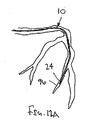
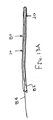
ここで図面を参照すると、図1A〜図2Bは、体管腔(図示せず)内へのアクセスを提供するための及び/または1または複数の器具(図示せず)を体管腔内へ送るための装置10の第1の好ましい形態を示す。体管腔は、例えば、患者の脈管構造内の管、尿生殖器管、呼吸器管、リンパ系、および患者の胃腸管内の通路等である。
(Detailed description of preferred form)
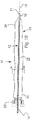
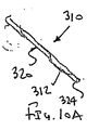
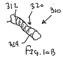
Referring now to the drawings, FIGS. 1A-2B provide access to a body lumen (not shown) and / or one or more instruments (not shown) into the body lumen. 1 shows a first preferred form of a
一般に、装置10は、装置10の「背骨」を与える可撓性の長尺状の補強部材12、および膨張可能な膜またはシース20を含む。補強部材12は、近位端部14および遠位端部16を含み、それらの間に長手方向の軸18を規定する。加えて、補強部材12は、患者の体(図示せず)の外側の位置から、介在する体内の通路を経由して、アクセスおよび/または処置されるべきサイトに進行させられるのに十分な長さを有し得る。遠位端部16は、体管腔に挿入されるための寸法および/または形状を有してよく、例えば、丸いまたは他の実質的に非外傷性の遠位先端17、「J」字の先端(図示せず)等を含む。
In general, the
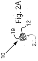
一つの形態において、補強部材12は中実の又は空洞を有するガイドワイヤ、カテーテル、糸等である。好ましくは、補強部材12は十分に可撓性であって、曲がりくねったアナトミー内を、切開または穿孔することなく進行することを容易にするが、近位端部14を押すことにより捩れ及び/又は曲げの実質的なリスクなしに遠位端部16を、体管腔を経由して進行させるのに十分なコラム強さ及び/又はトルク性能(torque-ability)を有する。補強部材12は、(図2Aおよび2Bに示すように)1または複数の内腔19であって、近位端部14と遠位端部16との間で延在して、例えば、流体がそれを経由して送られること及び/またはガイドワイヤもしくは他の器具(図示せず)を、それを経由させて受け入れることを可能にする内腔を有してよい。
In one form, the reinforcing
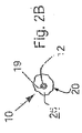
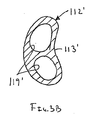
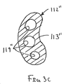
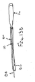
補強部材12は、実質的に対称的な断面、例えば、図2Aおよび2Bに示すように円筒形の断面を有してよく、あるいは、非対称な断面、例えば、図3A〜4Bに示すように弓形の断面を有してよい。図3A〜4Bに示す形態において、補強部材112は、その近位端部と遠位端部(図3A〜4Bには示さず)との間で少なくとも部分的に延びるグルーブ113を規定し得る。
The reinforcing
補強部材12または112は、種々の材料から、当業者に公知の種々の方法を用いて形成することができる。例えば、補強部材は、公知の方法(例えば、押出成形)を用いて、プラスチック、ガラス、コンポジット(もしくは複合材料)、および/または金属から形成してよく、それにより、可撓性およびコラム強さの所望の組合せを与える。ここで用いられている「背骨」「背骨部材」または「補強部材」という用語は、膨張可能な膜または他のシースを支持または補強して、シースを患者の体管腔に導入することを容易にし、並びに/または二次デバイスがシースの軸に沿って及び/もしくは全体の装置上をたどることを容易にし得る、長尺の可撓性を有する構造(または構造体)を含み得る。補強部材12は、約0.05〜5mm、好ましくは約0.2〜2mmの直径または他の最大断面を有してよい。
The reinforcing
図1Aおよび1Bを参照すると、膨張可能な膜またはシース20は、近位端部20、遠位端部24、および近位端部22と遠位端部24との間で延びる1または複数の側壁を含み、それにより少なくとも部分的に内腔26を規定する。ここで用いられている「シース」または「ガイドシース」という用語は、少なくとも部分的に内腔を規定する構造であれば、当該構造が実質的に管状であるか、あるいは部分的にのみ内腔を規定しているかにかかわらず、いずれの構造も含み得る。
With reference to FIGS. 1A and 1B, the inflatable membrane or
シース20は、図1Aおよび図2Aに示すような収縮した状態から、図1Bおよび図2Bに示すような拡張した状態に膨張することができる。シース20が収縮した状態にあるとき、装置10は低い輪郭(または姿勢もしくは高さ)となって、体管腔(図示せず)への挿入を容易にし得る。例えば、図2Aにおいて最も良く見られるように、シース20を、補強部材の周囲に又は補強部材に隣接して、(例えば、シース20の内腔26に対して内部真空および/または外力を使用して)折り畳み、撚り、巻き付け、または圧縮してよい。拡張した状態において、シース20は、展開され、撚りが戻され、巻き付けた状態が広げられ、または膨張して、例えば流体(例えば、薬剤、抗血栓剤等)および/または1または複数の器具をそこを経由させて受け入れるために、少なくとも部分的に内腔26を規定してよい。
The
シース20は比較的薄肉であるために、装置10は、シース20が収縮した状態にあるときに、例えば、約0.1〜約10mm、好ましくは約0.2〜約3mmの比較的低い輪郭(または姿勢もしくは高さ)となることができる。逆に言えば、シース20が膨張して拡張した状態に至ると、約0.3〜約100mm、好ましくは約0.3〜約20mmの間にある直径または他の最大断面を有する比較的大きい内腔26が提供され得る。
Because the
シース20は、補強部材12と比較して、相対的に薄く、可撓性を有する材料で形成することができる。したがって、シース20は、薄弱なもの(またはフリムジー(flimsy))であってよい、即ち、シース20が膨張および/もしくは収縮に対して殆ど抵抗を与えないように、殆ど又は全く剛性を有していなくてよく、ならびに/またはそれが展開されるアナトミーと実質的に一致してよい。ここで使用される「薄弱な(flimsy)」という用語は、シース20の材料がいずれかの特定の形状構成をとるようにバイアスをかけられていないことを意味し、したがって、シース20は、例えば、折り畳まれ又は圧縮されることにより、また、内部圧力または力を受けることにより、それに課されるいずれの形状および/または構造をも採用することができる。これを達成するために、シース20は、例えば、約0.001〜1.25mm、好ましくは約0.005〜0.06mmである比較的薄い壁厚を有してよい。
The
シース20は、比較的薄く、可撓性を有する構造体を形成し得る材料、例えば、ポリテトラフルオロエチレン(PTFE)、発泡ポリテトラフルオロエチレン(EPTFE)、フッ化エチレンプロピレン(FEP)、ポリエチレンテレフタレート(PET)、ウレタン、オレフィン、ポリエチレン(PE)、シリコーン、ラテックス、イソプレン、クロノプレン(chronoprene)等で構成してよい。シース20は、1または複数の器具(図示せず)を、内腔26を経由させて挿入することを容易にするために、滑らかな材料で形成されてよく、および/または液状シリコーンまたは他のコーティングを用いて親水性となるように被覆されてよい。好ましくは、シース20は、シース20の材料を展開する又は折り畳むことがシース20の膨張および収縮に主に寄与するように、実質的に非弾性である材料で形成される。したがって、シース20の全周長は収縮した状態と拡張した状態との間で実質的に変化しなくてもよい。別法として、シース20は、シース20の膨張および収縮にシース20の材料の弾性が二次的に寄与するように、即ち、シース20が拡張した状態に膨張するにつれてシース20の周長が増加するように、弾性材料で形成してよい。
The
シース20は実質的に非多孔性であってよい。別の形態において、シース20は、例えばその長さに沿って実質的に連続して又は1もしくは複数の位置にて、多孔性であって、内腔26内に送られる流体がシース20の壁を経由して所望のように送られることを許容してよく、例えば、シース20が延在する管の壁(図示せず)に流体を送ってよい。別の形態において、シース20は、1または複数の不連続な開口部(図示せず)を、その長さに沿って1または複数の場所に有してよい。
The
加えて又はこれに代えて、シース20は薄肉の金属箔を含んでよい。別法として、シース20は、薄いメッシュ(例えば、開孔ウレタンフィルム等)を含んでよい。さらに別の形態において、シース20の内側表面に、滑らかなコーティング、ライニング、うね立て等(図示せず)を付与することによって、および/または潤滑剤を塗布することによって、シース20の滑らかさを向上させることができる。所望の可撓性および滑らかさが得られるように、シース20は、そのような材料から成る単層または複数の層を有してよい。したがって、下記に説明するように、シース20は、容易に膨張し及び/又は体管腔の内側を覆って、摩擦を減らし及び/又は体管腔を経由して進行させられる器具を収容する。
In addition or alternatively, the
必要に応じて、シース20は1または複数の補強要素(図示せず)を含んでよい。例えば、プラスチック、ガラス、コンポジット(複合材料)および/または金属から成る、ワイヤ、糸、フィラメント等を、シース20の壁の外側表面および/もしくは内側表面に取り付けてよく、ならびに/またはシース20の壁に埋め込んでよい。加えて及び/または別法として、シース20は、壁材料から直接的に形成され得る比較的厚くされた領域を含んでよい。1または複数の補強要素は、所望の補強に応じて、シース20の周囲で円周上に及び/または螺旋状に延びてよく、ならびに/またはシース20に沿って軸方向に延びてよい。1または複数の補強要素は、シース20が拡張した状態に膨張したときに所望の形状または構成をとるようにバイアスをかけてよい。
If desired, the
別の形態において、シースは、補強部材に取り付けられてシース装置を与え得る、組まれた(または編まれた)材料の管状構造体又は部分的に管状である構造体(図示せず)であってよい。例えば、シースは、本明細書の他の部分で説明される形態に類似する、管状体またはその先端を補強部材に取り付け得るシートとなるように、組糸にされた、織られた、および/または編まれた、1または複数のプラスチックおよび/または金属のワイヤ、糸もしくは他のストランドから成ってよい。組糸(または組紐)にされたストランドは、上述したように、撚りをかける、折り畳む、捲縮(またはクリンプ)させる、および/もしくは巻き付けることによって、ならびに/または軸方向に移動させる(例えば、シースの両端が互いに遠ざかるように引っ張って、組糸(または組紐)にされた1または複数のストランドを軸方向の張力下で半径方向に圧縮することによって、収縮した状態に圧縮してよい。 In another form, the sheath is a tubular structure of assembled (or knitted) material or a structure that is partially tubular (not shown) that can be attached to a reinforcing member to provide a sheath device. It's okay. For example, the sheath is braided, woven, and / or similar to the forms described elsewhere herein, such that the sheath can be a sheet that can be attached to the tubular body or its distal end to the reinforcing member. Or it may consist of one or more knitted plastic and / or metal wires, yarns or other strands. The braided (or braided) strands are moved by twisting, folding, crimping (or crimping) and / or wrapping and / or axially as described above (eg, sheath One or more strands of braid (or braid) may be compressed in a contracted state by pulling them radially away under axial tension.
シース20の近位端部22は、シース20の操作および/もしくは1または複数の器具の内腔26への挿入を容易にし得る、環状のカラーまたはハンドルを含んでよい。加えて又はこれに代わるものとして、近位端部22は、内腔26を流体の近位フローから実質的にシールし得るが、器具が内腔26内に導入されることを許容し得る、当該分野において公知の止血バルブ(これも図示せず)を含んでよい。例えば、図1Aおよび図1Bに示すように、例えば、内腔26内への通路を制限するために、タフリー・ボースト(toughly borst)バルブ23をシース20の近位端部22に設けてよい。別法として、選択的に内腔26をシールし、シース20を操作し、および/またはシース20内への器具の導入を容易にするために、他の構造体、例えば、スリット・バルブ・アダプター、リムーバル・クランプ、o−リング、サイドポート、調節可能な固定デバイス等(図示せず)を設けてよい。
The
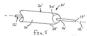
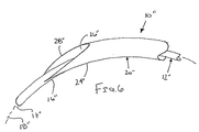
シース20の遠位端部24には、種々の形状構成のものが含まれる。例えば、図1Aおよび図2Aに示すように、シース20の遠位端部24は補強部材12の遠位先端17から近位側にずれていてよい。加えて、遠位端部24には、(例えば、図2に示すような)丸くされた形状、(例えば、図6に示すような)斜めに切断された形状、または装置10の非外傷性の侵入を容易にし得る他のテーパーを有する形状が含まれ得る。
The
例えば、図6に示すように、シース20”の遠位端部24”のテーパー28”は、装置10”がガイドワイヤ(図示せず)上を辿ることを容易にするものであってよく、および/または体管腔(これも図示せず)を経由させて装置10”を進行させることを容易にするものであってよい。テーパー28”は、シース20”が引っ掛かるおそれを最小限にすることができ、および/または装置10”が外部の拘束体なしに体管腔を経由して進行させられるときにシース20”を収縮した状態に萎ませることができる。別法として、シースの遠位端部は実質的に鈍い(または丸い)ものであってよい(図示せず)。
For example, as shown in FIG. 6, the
シース20の遠位端部24は実質的に閉じていてよく、あるいは1または複数の開口部を有していてよい。例えば、図2Aに示すように、シース20の遠位端部24は補強部材12の遠位端部16に取り付けられて、ルーメン26を遠位端部24にて実質的に閉じていてよい。シース20の遠位端部24は、シース20を補強部材から開放するように、補強部材12から取り外しできるようになっていてよい。
The
例えば、シース20の遠位端部24は、接着剤、半田または他の結合材料によって補強部材12に取り付けてよいが、それでもなお、例えばシース20を補強部材12に対して近位側に引っ張ることによって、又は補強部材12をシース20に対して遠位側に押すことによって、自由に引き裂かれるか、あるいは補強部材12の遠位端部16から分離されうる。別法として、器具(図示せず)は膨張可能な部材20を経由して進行させて、閉じた遠位端部24に対して押し付けることによって、補強部材12から遠位端部24を分離させてよい。これにより、シース20の遠位端部24に開口(図示せず)を形成することができ、それを経由して流体および/または1もしくは複数の器具(これも図示せず)を進行させることができる。
For example, the
別法として、遠位端部16、24を一緒に固定することができ、シース20の遠位端部24を補強部材12の遠位端部16から放すように作動し得る機械的なコネクタ(図示せず)を設けてよい。さらに別の形態において、選択的に開放または閉鎖することができるシンチループ(cinch loop)(図示せず)を遠位端部24に設けてよく、あるいは取り外しできるクリップ(これも図示せず)を設けてよい。加えて又はこれに代えて、シース20の遠位端部24は、例えば、生体吸収性接着剤または体液に曝されたときに分解して開口部を与える流体の他の材料(図示せず)を用いて、補強部材12の遠位端部16に接合されてよい。
Alternatively, the distal ends 16, 24 can be secured together and a mechanical connector (which can be actuated to release the
さらに別の形態において、図5に示すように、シース20’の遠位端部24’は、切断または貫通可能な領域、例えば、シース20’の側壁の比較的薄い又は弱くされた領域30’を含んでよい。弱くされた領域30’は、内腔26’内の器具(図示せず)が弱くされた領域30’に押し付けられて開口を形成するときに、弱くされたシーム(または縫い目)に沿って裂けてよく(図示せず)、または穴があけられてもよく(図示せず)、それにより器具が開口部を経由して体管腔内に進行することが可能となる。 In yet another form, as shown in FIG. 5, the distal end 24 'of the sheath 20' can be cut or penetrated, for example, a relatively thin or weakened region 30 'on the side wall of the sheath 20'. May be included. The weakened region 30 'tears along the weakened seam (or seam) when an instrument (not shown) in the lumen 26' is pressed against the weakened region 30 'to form an opening. (Not shown) or a hole may be drilled (not shown), which allows the instrument to travel through the opening and into the body lumen.
さらに別の形態において、図6に示すように、内腔26”を通過して挿入される器具(図示せず)が開口部28”から体管腔内に進行しうるように、シース20”の遠位端部24”は、内腔26”と連絡している1または複数の開口部28”、例えばテーパーを有する遠位端部24”によって規定される軸方向の開口部を含んでよい。
In yet another form, as shown in FIG. 6, a
別法として、図7に示すように、シース420の遠位端部424は、膨張可能なカフ430を含んでよい。カフ430は、シース420の周縁に取り付けられた膨らむことができる環状のバルーンであってよい。カフ430を膨張させる及び/又は萎ませるために、1または複数の内腔(図示せず)を、カフ430の内側と連絡している補強部材412内に設けてよい。膨張したカフ430は、シース420を体管腔(図示せず)内に固定するために使用してよく、および/または体管腔の遠位セグメントを膨張したカフ430よりも近位側のセグメントから分離するように作用してよい。
Alternatively, as shown in FIG. 7, the
例えば、シース420は、血管内に送られ、カフ430は血管を封止するために膨張させてよい。1または複数の血管内のマニピュレーションまたは処置を膨張したカフ430よりも近位側の血管内で実施してよい。したがって、塞栓のデブリ(又は破片)が血管の近位部分内で放出される場合には、カフ430はデブリが血管の遠位部分に送られることを防止し得る。
For example, the
別の形態において、シース420の近位開口部426は、血管(図示せず)内に位置させてよく、それにより、近位開口部426から開始し、シース420の内腔426を経由して遠位カフ430に延びる体管腔内に位置し得るバイパスまたはシャントチャンネルを形成する。さらに別の形態において、1または複数の内腔(図示せず)をシース420それ自身の壁の中に又は壁に沿って形成してよい。必要に応じて、1または複数のカフまたはポケット(図示せず)をシース420に沿って1または複数の箇所に形成して、例えば、シース420をしっかりと固定してよく、もしくは例えば造影剤の逆行注入の目的のためにフローを制限してよく、および/またはシース420にバイアスをかけて特定の形状または構造に膨張させてよい。
In another form, the
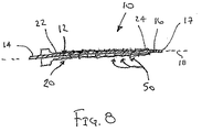
図1A〜図2Bに示すように、1つの形態において、シース20は補強部材12の近位端部および遠位端部の間の1または複数の箇所にて補強部材12に取り付けられる、実質的に閉じた管状体であってよい。例えば、シース20は、遠位端部24、16においてのみ補強部材に取り付けられてよい。別法として、例えば、補強部材12がシース20の壁に沿って配置されるときには、シース20は、シース20の近位端部22、遠位端部24もしくはその付近、またはその両方にて、補強部材12に取り付けられてよい。
As shown in FIGS. 1A-2B, in one form, the
必要に応じて、シース20は補強部材12に、例えば近位端部22と遠位端部24との間の1または複数の追加の箇所にて、間隔をあけて取り付けられてよい。別法として、補強部材12はシース20の近位端部22と遠位端部24との間のシース20に実質的に連続的に取り付けられてよい。補強部材12は、シース20の内側、即ち、内腔26内に取り付けられてよく、あるいはシース20の外側に取り付けられてよい。シース20および補強部材12は公知の方法(例えば、接着剤、超音波、溶接、縫糸または他のストランド(図示せず)による接合)を用いて、互いに取り付けられる。
If desired, the
別法として、補強部材12は、シース20の近位端部22と遠位端部24との間で延びるシース20の独立したポケットまたは内腔(図示せず)に収容されてよい。補強部材12は、上述したように、ポケットまたは内腔内で固定されていなくてよく(ルーズであってよく)、あるいは内腔内でシース20に取り付けられていてよい。
Alternatively, the reinforcing
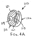
図4Aおよび図4Bに示す別の形態において、シース120はその先端121が補強部材112に取り付けられたシート材料であってよい。したがって、補強部材112は、部分的に内腔126をシース120のシートとともに規定する。前述したように、シース120は実質的に補強部材112の長さに沿って連続的に取り付けられていてよいが、別法として、シース120は補強部材112に断続的に取り付けられていてよい。
In another form shown in FIGS. 4A and 4B, the
必要に応じて、上述したシースのいずれか(例えば、図1A〜図2Bに示すシース20)は、近位端部22から遠位端部24に向かって少なくとも部分的に延びる1または複数のシーム(図示せず)に沿って裂けるように、および/または補強部材12から分離するように構成されていてよい。例えば、シース20は、2またはそれよりも多い組の間隔をあけて配置された開口部および/もしくは近位端部22と遠位端部24との間で延びる比較的薄肉のシーム(図示せず)を含んでよい。加えて又はこれに代えて、シース20の材料は、長手方向の軸18に沿って優先的に裂けて、シース20が2またはそれよりも多い長手方向のストリップ(図示せず)に分離するようにバイアスがかけられてよい。これらの特徴は、器具(図示せず)が内腔26内に配置される場合に、例えば、器具が実質的に取り外せないように体管腔内に埋め込まれることを予定しているときに、体管腔からシース20および/または装置全体10を取り除くことを容易にし得る。
Optionally, any of the sheaths described above (eg, the
装置10はまた、患者の脈管構造または他の体内通路を経由して進行する間、シースをカバーするおよび/または保護するための拘束体(またはコンストレイント)を含んでよい。例えば、図8に示すように、1または複数のワイヤ、糸、モノフィラメント、または他のストランド50をシース20の周囲に配置させて、シース20をその収縮した状態に維持してよい。ストランド50は、シース20の周囲にて延びる複数のループを含んでよく、また、ループを経由して供給される1または複数の除去可能なフィラメント(図示せず)を用いて固定してよい。シース20を開放するために、1または複数の除去可能なフィラメントをループから、例えば除去可能なフィラメントを装置10の近位端部から引っ張ることにより除去してよい。ループはそれから解除されて、それらの1または複数のストランドが取り除かれる。
The
別法として、他の拘束体(例えば、外被(もしくはラップ)、繋ぎ材(もしくはタイ)、接着剤、生体吸収性のカプセル材料(例えば、スクロース)等を使用してよい(図示せず)。さらに別の形態において、カテーテル、シース、または他の管状部材(これもまた図示せず)を設けてよい。例えば、図13Aおよび図13Bに示すように、シース20が収縮した状態にあるときに、装置10(または本明細書で説明する他のシース装置のいずれか)が配置され得る内腔82を含み得るカテーテル80を使用してよい。装置10は、プッシング(または押しこみ)エレメント84(例えば、ワイヤまたは補強部材12(図1A〜2B参照、図13Aおよび図13Bでは図示せず)から延びる他の長尺状部材)を含んでよい。プッシング・エレメント84をカテーテル80に対して遠位側に進行させて、図13Bに示すように装置10を展開させてよく、あるいは、図13Aに示すように近位側に進行させて装置10をカテーテル80内に引き込んでよい。
Alternatively, other restraints (eg, jacket (or wrap), tether (or tie), adhesive, bioabsorbable capsule material (eg, sucrose), etc. may be used (not shown). In yet another form, a catheter, sheath, or other tubular member (also not shown) may be provided, for example, when the
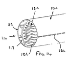
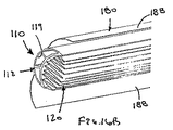
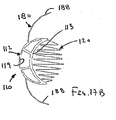
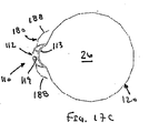
図16A〜17Cに示す別の形態において、外側シース180を設けてよい。外側シース180は、少なくとも部分的にシース装置110に結合されて膨張可能なシース120を収縮した状態に維持する。外側シース180は、例えば、約0.005〜0.06mmの肉厚を有する、膨張可能なシース120に類似する材料で形成されてよい。したがって、外側シース180は実質的に可撓性であってよく、および/または装置110の患者の体腔内での進行を促進しやすいものであってよい。
In another form shown in FIGS. 16A-17C, an
装置110は、図3A〜4Bを参照して説明したものと同様の補強部材112を含んでよい。前記他の形態と同様に、当該補強部材112には、膨張可能なシース120が取り付けられてよい。補強部材112は、1または複数の内腔119を含んでよく(3つの例示的な内腔を図示する)、外側シース180は補強部材112に、例えば補強部材12の長さに沿って連続的又は間欠的に接合され、あるいは取り付けられてよい。補強部材112内の1または複数の内腔は、装置110の例えば近位端部から遠位端部まで、装置110を経由する注入、吸引、撹拌および/または潅流を提供しうる。別法として、外側シース180は、膨張可能なシース120に直接的に、例えば膨張可能なシース120の外周上の位置に及び/又は長さに沿って、取り付けてよい(図示せず)。
The
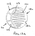
図16Aおよび図17Aにおいて最も良く見られるように、外側シース180は少なくとも部分的に(単独で又は補強部材112とともに)内腔182を規定してよい。当該内腔182内には、膨張可能なシース120が収縮した状態で収容されてよい。加えて、外側シース180は、例えば外側シース180の近位端部と遠位端部(図示せず)との間で延びる1または複数の弱くされた領域186を含んでよい。弱くされた領域186は、間隔をあけて配置された開口部を有してよく、および/または外側シース180に沿って実質的に軸方向に延びてよい連続的もしくは不連続な薄肉領域を有してよい。
As best seen in FIGS. 16A and 17A, the
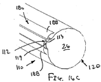
弱くされた領域186は、内部圧力を作用させて膨張可能なシース120を拡張した状態に向かって膨張させるときに分離し得る。例えば、弱くされた領域186が裂ける又は分離するのに十分な圧力が生じるまで、流体を外側シース180の内腔182内に導入してよい。別法として、膨張可能なシース120が半径方向に外向きに外側シース180を押して、弱くされた領域186の分離が生じるまで、膨張可能なシース120が膨張するように、流体または器具(図示せず)を、膨張可能なシース120内に導入してよい。
The weakened
例えば、使用中、装置110および外側シース180は、図16Aおよび図17Aに示すように、外側シース180を損傷することなく、かつ膨張可能シース120を収縮した状態にして、体管腔(例えば血管等(図示せず))を経由させて進行させてよい。所望の位置に到達すると、内部圧力が加えられて、図16Bおよび図17Bに示すように、外側シース180の弱くされた領域186を分離させる。それから、膨張可能なシース120は、図16Cおよび図17Cに示すように、その拡張された状態に膨張させてよい。外側シース180の分離した部分188は、それらが膨張可能なシース120の膨張を実質的に妨げないように、十分な可撓性を有するものであってよく、および/または膨張可能なシース120が膨張するときに、それの形状に実質的に一致するものであってよい。
For example, in use, the
さらに別の形態において、図1A〜図2Bを参照するに、拘束体がシース20の周囲に設けられる場合には、シース20を補強部材12に取り付ける必要はない。シース20(例えば管状体)は、単に補強部材12の周囲に配置されて、拘束体に挿入される又は拘束体により拘束される前に、補強部材12の周囲で又は補強部材12に近接して、折り畳まれ、撚られ、捲縮され、または圧縮されて、収縮した状態にされる。加えて又はこれに代えて、以下に説明するように、真空圧力を、単独で又は折り畳みとともに、シース20を圧縮するために使用してよく、および/または流体を内腔26内に注入して、シース20を膨張させてよい。
In still another embodiment, referring to FIGS. 1A to 2B, when the restraint is provided around the
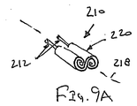
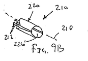
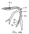
図1A〜2Bにおいては一つだけの補強部材が示されているが、本発明のシース装置は1よりも多い補強部材を含んでよいことが理解されよう。例えば、図9Aおよび図9Bに示すように、2つの補強部材212を含むシース装置210の態様が示されており、当該補強部材には膨張可能な膜または他のシース220が取り付けられている。シース220は、例えば補強部材212を長手方向の軸218の周りで撚って、シース220を補強部材212の周囲に巻き付けることにより圧縮して、図9Aに示す収縮した状態に圧縮してよい。シース220は、補強部材212の撚りを解くことにより、巻きが解かれて、図9Bに示すように拡張した状態に膨張させられ、それによりシース220内に内腔226を与える。
Although only one reinforcing member is shown in FIGS. 1A-2B, it will be appreciated that the sheath device of the present invention may include more than one reinforcing member. For example, as shown in FIGS. 9A and 9B, an embodiment of a
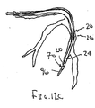
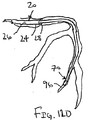
加えて、図1A〜図2B、図9Aおよび図9Bに示す補強部材12、212は概して長手方向の軸18、218と平行に延びるが、他の補強部材をまた、補強部材12、212に加えて又はそれに代えて設けてもよい。例えば、図10Aおよび図10Bに示すように、管状のシース320の周囲で螺旋状に延びる1または複数の補強部材312を設けてよい。補強部材312は、シース320の外側または内側表面に取り付けられた、またはシース320の壁内に埋め込まれた、ワイヤまたは他のストランドである。1または複数の螺旋状補強部材はまた、シース320を膨張させる及び/又は萎ませることを容易にする。例えば、補強部材312の端部は、一方の端部から軸方向に引き出して、シース320を圧縮してよい。加えて又はこれに代えて、補強部材312には、図10Bに示すような構成となるようにバイアスがかけられて、シース320が拡張した状態に膨張することを容易にする。
In addition, although the reinforcing
加えて又は別法として、円周もしくは周縁のリングまたはストランド(図示せず)をシース320の周囲に設けてよい。そのような補強リングまたはストランドは、上述した螺旋状の補強部材と同様に、シース320を支持し、および/または拡張した状態に向けてシース320にバイアスをかけてよい。
Additionally or alternatively, circumferential or peripheral rings or strands (not shown) may be provided around the
さらに、上述した装置は、単一の内腔を有する膨張可能なシースを含むが、1または複数のシースであって、各々が1または複数の内腔を有するシースを設けることが可能であり得ることが理解されよう。例えば、シースは、例えば押出成形により、複数の内腔を有するように製造してよい。別の例として、上述したものと同様の複数の膨張可能なシースを、互いに対して、および/または1もしくは複数の共通する補強部材に取り付けて、複数の膨張可能な内腔を有する装置を与えるようにしてよい(図示せず)。シースは互いに同心であってよく、例えば、互いの内部に緩く配置されていてよく、あるいは、1または複数のエッジに沿って互いに対して取り付けてよい。別法として、シースは、互いに隣接するように配置してよく、例えば、一緒に又は1もしくは複数の共通の補強部材に取り付けてよい。したがって、複数の器具を、互いに連動させてシースの各内腔を経由させて進行させることができる。 Further, the device described above includes an inflatable sheath having a single lumen, but it may be possible to provide one or more sheaths, each having one or more lumens. It will be understood. For example, the sheath may be manufactured to have a plurality of lumens, for example by extrusion. As another example, a plurality of inflatable sheaths similar to those described above may be attached to each other and / or to one or more common reinforcement members to provide a device having a plurality of inflatable lumens. You may do it (not shown). The sheaths may be concentric with each other, for example, loosely disposed within each other, or attached to each other along one or more edges. Alternatively, the sheaths may be positioned adjacent to each other, for example, attached together or to one or more common reinforcing members. Accordingly, a plurality of instruments can be advanced via each lumen of the sheath in conjunction with each other.
必要に応じて、上述したシース装置の1または複数のコンポーネント(例えば、補強部材、シース、および/または拘束体)は、1又は複数の放射線不透過性のマーカー(例えば放射線不透過性材料、放射線不透過性インクもしくは他の堆積物等で形成されたバンドまたは他のエレメント(図示せず))を含んでよい。そのようなマーカーおよび/または放射線不透過性材料は、装置を使用している間、例えば、蛍光X線透視法を使用して、装置を撮像すること及び/またはモニタリングすることを容易にし得る。加えて、互いに間隔をあけて配置されているマーカーを、例えば互いから既知の距離にて、所定の方法で設けて、距離を示してよく、ならびに/または患者の脈管構造のマッピングおよび/もしくはアクセスを容易にしてよい。別法として、当該分野で周知の他の外的または内的画像化システムおよび方法(例えば、磁気共鳴映像法、超音波等)を用いてよい。 Optionally, one or more components (eg, reinforcing members, sheaths, and / or restraints) of the above-described sheath device may include one or more radiopaque markers (eg, radiopaque material, radiation, Bands or other elements (not shown) formed of impermeable ink or other deposits or the like may be included. Such markers and / or radiopaque materials may facilitate imaging and / or monitoring of the device while using the device, eg, using fluoroscopy. In addition, markers that are spaced apart from each other may be provided in a predetermined manner, eg, at a known distance from each other, to indicate the distance and / or mapping of the patient's vasculature and / or Access may be facilitated. Alternatively, other external or internal imaging systems and methods well known in the art (eg, magnetic resonance imaging, ultrasound, etc.) may be used.
本発明のシース装置は、種々の体管腔にアクセスを与えて、例えば、診断及び/または治療処置を実施するために使用してよい。一般に、収縮した状態にある膨張可能なシースを有する装置は、患者の体における生来の又は人為的に形成した入口サイトに導入してよく、患者の体の中の1または複数の体内通路(形成された通路を含む)(例えば、切開面)に進行させてよい。好ましくは、装置は、シースの近位端部を入口サイトの外側にとどめたまま、入口サイトから、シースの遠位端部がターゲットとする体管腔内に位置するまで進行させられる。装置は、その低い輪郭のために、比較的小さくてアクセスするのが難しい体管腔に遠位端部が位置するまで、曲がりくねったアナトミーを通過して容易に進行することができる。 The sheath device of the present invention may be used to provide access to various body lumens, for example, to perform diagnostic and / or therapeutic procedures. In general, a device having an expandable sheath in a deflated state may be introduced into a native or artificially formed entrance site in the patient's body, and one or more body passageways (formation) in the patient's body. (E.g., the cut surface). Preferably, the device is advanced from the entry site while the proximal end of the sheath remains outside the entry site until the distal end of the sheath is located within the targeted body lumen. Due to its low profile, the device can easily progress through a tortuous anatomy until the distal end is located in a body lumen that is relatively small and difficult to access.
シースは、拡張した状態にそれから膨張させられ、それによりシース内に内腔を規定する。したがって、シースにより規定される内腔は、入口サイトから介在する体内通路を経由して目的とする体管腔またはサイトに延びて、入口サイトからターゲットとする体管腔またはサイトに至るパス(もしくは通路)を与え得る。必要に応じて、上述のように、シースが拘束体により収縮した状態に維持され及び/または被覆される場合には、シースが拡張した状態に膨張させられる前に、拘束体は少なくとも部分的にシースから除去してよい。 The sheath is then expanded to an expanded state, thereby defining a lumen within the sheath. Accordingly, the lumen defined by the sheath extends from the entrance site via the intervening body passage to the target body lumen or site and passes from the entrance site to the target body lumen or site (or Path). Optionally, as described above, if the sheath is maintained in a contracted state and / or covered by the restraint, the restraint is at least partially prior to being expanded to the expanded state. It may be removed from the sheath.
以下において例示するような診断および/または治療処置を、シースにより規定される内腔を介して体管腔内で実施してよい。処置が終了すると、シースは体管腔から取り出され、好ましくは患者の体から取り出される。 Diagnostic and / or therapeutic procedures as exemplified below may be performed in a body lumen via a lumen defined by a sheath. When the procedure is complete, the sheath is removed from the body lumen and preferably removed from the patient's body.
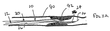
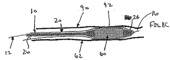
例えば、図11A〜図11Fに示すように、シース装置10はステント60を血管90内の狭窄部または閉塞部92内に送るのを容易にするために使用してよい。血管90は、患者の冠状、末梢、または神経脈管構造内の冠状血管、頸動脈網、大脳または他の血管内の動脈もしくは静脈であってよい。
For example, as shown in FIGS. 11A-11F, the
図11Aに示されるように、収縮した状態にあるシース20を備えた装置10は、遠位端部16がターゲットとする血管90内に配置されるまで、経皮的な入口サイト(図示せず)から進行させられ、患者の脈管構造内に導入される。例えば、ガイドワイヤ(図示せず)が、常套的な方法を使用して、経皮的な入口サイトから狭窄部92を越えて、予め血管90へ配置される。装置10は、図11Aに示すように、シース20の遠位端部24が狭窄部92内に又は狭窄部92を越えて配置されるまで、ガイドワイヤ上を進行させてよい。装置10が補強部材12を含む場合、補強部材12は、ガイドワイヤ内腔(図示せず)を含んで、ガイドワイヤがガイドワイヤ内腔を経由して挿入されて、装置10をガイドワイヤ上で進行させることができるようになっていてよい。別法として、シース20は、その収縮した状態において、予めガイドワイヤを配置することなく、進行させてよい。シート20または補強部材12の遠位先端は、進行の間に脈管構造が外傷を受けることを避けるために十分に可撓性を有する又は柔軟であることによって、あるいは進行の間の操縦を可能にするように成形される、成形可能である、または変形可能であることによって、脈菅構造のナビゲーションを容易にし得る。
As shown in FIG. 11A, the
装置10が血管90内に配置されると、シース20を収縮した状態に保持する又はシース20を被覆する拘束体(図示せず)を、例えば、機械的、化学的(例えば、生体吸収性縫合糸)および/または生理学的(例えば、加熱活性化ニチノール・タイ(nitinol tie))に除去してよい。例えば、上述したように、これは、覆っているカテーテルまたはシース(図示せず)を待避させること、またはシース20を取り囲むループまたは他のストランド(これも図示せず)を取り除くことを伴ってよい。
When the
それから、シース20は、その収縮した状態からその拡張した状態に膨張させてよい。例えば、流体(図示せず)を内腔26内に導入して、シース20を膨張させてよく、その結果、シース20は膨張して、例えば入口サイトと血管90との間で、患者の脈管構造内の1または複数の脈管の壁と一致(もしくは壁をライニングする)又は接触する。別法として、図11Bに示すように、1または複数の器具(例えば、カテーテル62およびステント)が内腔26を経由して進行させられるときに、シース20が自由に膨張するようにシース20は単に解放されてよい。
The
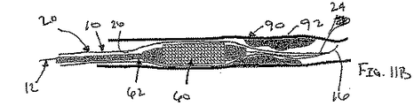
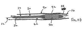
図11Bを参照して説明すると、1または複数の器具を、シース20により規定される内腔26を経由して血管90内に導入してよい。例えば、ステント60を担持するカテーテル62をシース20の近位端部22(図1A〜11Fには図示せず)内に導入して、ステント60が血管90内に配置されるまで、内腔26を経由して進行させてよい。ステント60は、いずれの公知の人工血管(例えば、バルーンにより拡張可能である又は自己膨張するステント)を含んでいてよく、また、カテーテル62は、例えば、バルーン、シース、ノーズ・コーンおよび/または他のエレメントを含む、いずれの公知の送出装置を含んでいてよい。必要に応じて、他の器具(例えば、血栓摘出デバイス、撹拌デバイス、バルーンカテーテル、フィルタ、閉鎖デバイス等)(図示せず)をシース20を経由させて、カテーテル62の前または後に導入して、例えば、狭窄部92を広げる及び/又は遠位側の保護を与える(即ち、処置の間に放出された塞栓物質を捕捉する)ようにしてよい。
With reference to FIG. 11B, one or more instruments may be introduced into the
装置10が進行させられ得るガイドワイヤまたは他のレールは、1または複数の器具がシース20を通過して進行させられる前に除去してよく、あるいはガイドワイヤは狭窄部92を越える所定の位置にとどまっていてよい。加えて、装置10が同心の補強部材12をシース20内に含む場合には、カテーテル62は、図11Bに示すように、補強部材12上を(即ち、補強部材12とシース20との間を)進行させてよい。別法として、シースが補強部材から取り外し可能である場合には、補強部材12をシース20から除去してよい(図示せず)。さらに別の形態において、図4Aおよび図4Bに示されるように、器具(図4Aおよび図4Bには示されていない)は補強部材12に隣接する内腔126を経由して進行させてよい。したがって、カテーテルまたは他の器具をシース20内で運ぶことの1つの利点は、器具内のガイドワイヤ・ルーメンの必要がなくなり得るということであり、それにより、器具の輪郭(または姿勢もしくは高さ)を、ガイドワイヤ上で送られる器具と比較して小さくすることが可能となる。
The guidewire or other rail through which the
図11Bを参照してさらに説明を続けると、滑らかな性質のシース20は、カテーテル62が内腔26を通過して進行することを容易にし、したがって、患者の脈菅構造の狭い、曲がりくねった、病変した、および/または脆い領域を通過して進行することを容易にする。例えば、シース20は、器具(例えばカテーテル62)を狭い領域に押し付ける又は当該領域内に押しすすめるときに生じる軸方向の力を、半径方向の力に変え得る。半径方向の力は、狭い領域を広げて、器具がそこを通過することを容易にする。この動作は、例えば、内腔26内に流体を導入することによって、シース20を内部で(または内側から)加圧することにより、さらに強化され得る。したがって、シース20は、図11Cに示すように、ステント60が狭窄部92を越えて(または狭窄部92を横切って)進行することを容易にし得る。
Continuing further with reference to FIG. 11B, the smooth nature of the
加えて、シース20は、内腔26の滑らかな通路に沿ってシース20内を進行する器具をガイドし得るので、シース20は、脈管構造内の管の壁に孔をあける、もしくは当該壁を傷つける、および/または器具を妨げるリスクを実質的に減少させ得る。さらに、シース20は膨張して壁を覆い、それによりプラークおよび血栓をシース20と管の壁との間で拘束するので、シース20は、塞栓物質等が患者の脈管構造から移動するリスクを最小限にし得る。
In addition, the
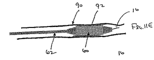
シース20の遠位端部24が閉じられている場合、開口部28を形成して、1または複数の器具を内腔26を経由して進行させてシース20から出すようにしてよい。例えば、上述したように、第1の器具(例えばステント60を担持するカテーテル62)が内腔26を経由して進行し、図11Dに示すように遠位端部24に押し当てられるときに、遠位端部24を補強部材12から分離させてよい。別法として、シース20の遠位端部24が補強部材12に取り付けられる場合には、例えば補強部材12を遠位方向に進行させる及び/又はシース20を近位方向に引くことにより、遠位端部24を補強部材12から分離させて、開口部28を、例えばカテーテル62または他の器具(図示せず)を内腔26内に導入する前または後に形成してよい。
When the
さらに別の形態において、図5に示し、また上記において説明したように、シース20’は、開口部(図5において図示せず)を形成するために使用されうる、弱くされた領域30’を遠位端部24’に含んでよい。十分な内部圧力が生じて、弱くされた領域30’が破壊する又は裂けるまで、例えば、流体(例えば生理食塩水および/または造影剤)をシース20’の内腔26’内に導入してよい。別法として、器具(例えば、図11B〜11Fに示すカテーテル62、ガイドワイヤ等(図示せず))を内腔26’内で進行させて、弱くされた領域30’に押し付けて、弱くされた領域30’を壊して、開口部を形成してよい。さらに別の形態において、例えば図6に示すような、開口部28”が既に遠位端部24”に設けられたシース20”を含む装置10”を使用してよい。
In yet another form, as shown in FIG. 5 and described above, the
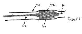
図11Eに戻って説明すると、ステント60が狭窄部92を越えて配置されると、シース20は少なくとも部分的に後退させられて、ステント60および/またはカテーテル62を、管90および/または狭窄部92内にて露出させる。図11Fに示すように、ステント60は、例えば狭窄部92を広げる又は狭窄部92に足場を設ける方法を用いて、拡張させてよい。ステント60が送られると(および追加の処置が完了すると)、カテーテル62および装置60は、入口サイトを経由させて管90および患者の脈管構造から除去してよい。
Returning to FIG. 11E, once the
一つの形態において、カテーテル62または他の器具(図示せず)はまずシース20内へ、シース20を経由させて除去してよく、それからすぐにシース20を除去してよい。所望の場合には、シース20を管90から除去する前に、シース20の内腔26内から流体を例えば真空源をシース20の近位端部に接続して吸引することにより、シース20を拡張した状態から少なくとも部分的につぶしてよい。別法として、カテーテルまたは他の管状部材(図示せず)を、シース20上を進行させて、その除去を容易にしてよい。別の形態において、シース20は、例えば、シース20内に器具を退行させることによって、カテーテル62または他の器具とともに同時に除去してよい。さらに別の形態において、カテーテル62または他の器具を取り除く前に、シース20を患者から除去してよい。外部の撮像装置、例えば、蛍光透視法、MRIおよび/または超音波を使用して処置をモニターしてよいこと、部品(例えば、装置10、ステント60および/またはカテーテル62)は、それが進行および/または除去している間に撮像を容易にするための要素(例えば、放射線不透過性のマーカー(図示せず))を含んでよいことが理解されよう。
In one form, the
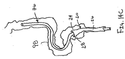
図12A〜12Dを参照して、患者の脈管構造内のターゲットとする管へのアクセスを与えるために、シース装置10(または上述したシース装置のいずれか)を使用する別の方法を説明する。具体的には、装置10は、例えばペースメーカ用の電気リード70を、例えば心臓の左心室に隣接する冠静脈96内に送るために使用してよい。図12Aに示すように、最初に、補強部材(図示せず)により担持されている膨張可能なシース20が収縮した状態にある装置10を冠静脈96内に進行させてよい。
With reference to FIGS. 12A-12D, another method of using the sheath device 10 (or any of the sheath devices described above) to provide access to a target tube within a patient's vasculature will be described. . Specifically, the
例えば、シース20が畳まれた状態にて装置10を、経皮的な入口サイト(図示せず)(例えば、大腿深静脈または鎖骨下静脈)から導入して、患者の静脈系を経由して心臓の右心房内および冠状静脈洞(図示せず)内に進行させて、ターゲットとする冠静脈96に到達させてよい。装置10は、先に説明した方法と同様にしてガイドワイヤ(図示せず)上を進行させてよい。その比較的低い輪郭(または高さ)のために、装置10はより小さい冠静脈にアクセスすることができてもよく、あるいは、ターゲットとする冠静脈内へ常套の装置よりもさらに遠くに進行させてよい。
For example,
装置10がターゲットとする静脈96内またはその付近に配置されると、装置10の位置決めを容易にするために、蛍光透視および/または他の撮像方法を使用してよい。装置10(例えば、シース20の遠位端部24、覆っている拘束体等)は、撮像を容易にするために、1または複数の放射線不透過性のマーカー(図示せず)を含んでよい。加えて又はこれに代えて、造影剤を、例えば、装置10の補強部材(図示せず)中の流体内腔を経由させて、および/またはシース20の内腔26を経由させて、静脈内に導入して、撮像を容易にしてよい。そのような撮像は、付近の構造に対するシース20の位置を同定して、装置10がターゲットとする位置に可能なかぎり接近した箇所に進行することを確実にするために使用することができる。好ましくは、装置10は、シース20の遠位端部24が患者の心臓の左心室(図示せず)に隣接する冠静脈96内に配置されるように、進行させられる。
Once the
図12Bに示すように、シース20を入口サイトとターゲットする静脈96との間で膨張させてよい。拘束体(図示せず)が設けられている場合には、それはシース20を膨張させる前に除去してよい。例えば生理食塩水および/または造影剤を含む流体を、シース20内に導入して、シース20を拡張した状態に膨張させてよい。シース20内に送られる造影剤はまた、静脈96を撮像することをも容易にする。例えば、シース20の遠視端部24が最初は閉じている場合、内腔26内に送られる造影剤は、シース20を膨張させて周囲の管の形状に適合させることがあり、それにより、シース20が展開される管を撮像することを容易にする。
As shown in FIG. 12B, the
図12Bおよび図12Cに示すように、電気ペーシングリード70をシース20の内腔26を経由させて、リード70の先端72がターゲットとする静脈96内に位置するまで進行させてよい。上述した方法と同様に、シース20は、内腔26と連絡している開口部28をその遠位端部24に既に含んでいてよく、あるいは開口部はシースの閉じた遠位端部24(図示せず)に形成されてよい。先端72は、例えばシース20を後退させることによって、又は先端72を開口部28を経由させてシース20の遠位端部24を越えて進行させることによって、シース20から展開させてよく、それにより先端72を静脈96内に実質的に固定する。
As shown in FIGS. 12B and 12C, the
図12Dに示すように、シース20は、それから静脈96および患者の脈管構造から除去してよい。好ましくは、シース20は1つ、2つまたはそれよりも多いピースに分割させて、シース20が容易にリード70の周囲から除去されるようにしてよい。リード70の埋め込みは、それから常套の方法を使用して完了させ得る。
As shown in FIG. 12D, the
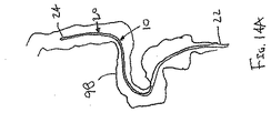
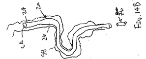
図14A〜14Cを参照すると、上述したいずれかの形態のシース装置10を使用して、結腸内視鏡76を患者の結腸98内に送る方法が示されている。図14Aに示すように、装置10は、シース20を収縮した状態にして、結腸98内に進行させられる。図14Bに示すように、シース20は所望の位置に進行すると、拡張した状態に膨張させられて、内腔26を規定する。結腸内視鏡76は、先に説明した形態と同様に、シース20の内腔26を経由して進行させることができる。所望の場合には、シース20は、結腸内視鏡76がシース20を経由して進行するときに結腸内視鏡76が結腸76内の周囲の組織を撮像し得るような形状としてよい。例えば、シース20の材料は、結腸内視鏡76により使用される可視光(またはスペクトルの他の部分)に対して実質的に透明であってよい。別法として、他の用途において、シース20は、周囲組織の撮像を可能にするために、他の撮像源(例えば、超音波エネルギー)が実質的に自由にシース20を通過することを許容してよい。シース20は、図14Cに示すように、結腸内視鏡76の周囲から除去してよく、あるいは例えば処置の後の除去を容易にするために、少なくとも部分的に結腸内視鏡76の周囲にとどまらせてよい。加えて、シース20は、流体(例えば、空気、二酸化炭素等)を胃腸管腔内に導入するようになっていてよい。
14A-14C, a method of delivering a
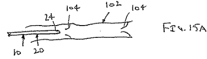
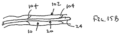
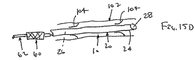
図15A〜15Cを参照して説明すると、本発明のシース装置は、患者の静脈システム内に1または複数の器具が逆行する進行を容易にし得る。例えば、図15Aに示すように、複数の弁104を含む例示的な静脈102が示されている。図15Bに示すように、シース装置10(それは、本明細書で説明する形態のいずれであってよい)は、膨張可能なシース20が収縮した状態にて、静脈102内に進行させることができる。所望の位置に進行すると、図15Cに示すように、シース20をその拡張した状態に膨張させてよく、それによりバルブ104が開かれ、また、シース20には静脈102を通過する比較的大径の内腔26を設けてよい。上述した形態と同様にして、1または複数の器具(例えば、図14Dに示すようなステント60およびカテーテル60)を、処置を完了させるために内腔26を経由して進行させてよい。
Referring to FIGS. 15A-15C, the sheath device of the present invention may facilitate the retrograde progression of one or more instruments within a patient's venous system. For example, as shown in FIG. 15A, an
本発明のシース装置はまた、他の診断および/または治療処置を脈管構造内で実施するために使用してよい。例えば、装置は、撮像エレメント(例えば血管内超音波法(IVUS)のデバイス、内視鏡および光ファイバーエレメント等)を送るための、ならびに/または治療用器具(例えば、血管形成カテーテル、ステント・デリバリー・デバイス、およびアテローム切除術または血栓摘出術用のデバイス等)を送るための膨張可能な内腔を与えてよい。 The sheath device of the present invention may also be used to perform other diagnostic and / or therapeutic procedures within the vasculature. For example, the apparatus may deliver imaging elements (eg, intravascular ultrasound (IVUS) devices, endoscopes, fiber optic elements, etc.) and / or therapeutic instruments (eg, angioplasty catheters, stent delivery devices). Devices, and devices for atherectomy or thrombectomy, etc.) may be provided.
別の方法において、本発明のシース装置は、患者の体の内部の他の体管腔に、アクセスする及び/又は器具を運ぶために使用することができる。例えば、装置は、患者の尿生殖路、呼吸器管、消化管、リンパ管系、または脈管(もしくは血管)系内で使用してよい。加えて、装置は、外科的に形成される開口部内に導入し、また、外科的に形成された通路(例えば、バイオプシーを得るために間質腔内に形成される通路)内に進行させてよい。 In another method, the sheath device of the present invention can be used to access and / or carry instruments to other body lumens within a patient's body. For example, the device may be used within a patient's urogenital tract, respiratory tract, digestive tract, lymphatic system, or vascular (or vascular) system. In addition, the device can be introduced into a surgically formed opening and advanced into a surgically formed passage (eg, a passage formed in the interstitial space to obtain a biopsy). Good.
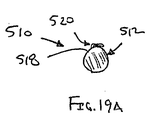
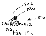
図18および図19A〜19Cを参照して、本発明の別の形態のシース装置510を説明する。一般的に、装置510は、カテーテルまたは他の長尺部材512および膨張可能なシース520を含む。カテーテル512は、均一な又は可変なフレキシビリティを有する材料で形成される長尺の管体であってよく、例えば十分に可撓性である遠位端部514を有する。カテーテル512は、近位端部(図示せず)から遠位端部514まで延びる1または複数の内腔(図示せず)を含んでよい。
A
好ましい形態において、カテーテル512は1または複数の診断用または治療用エレメントを遠位端部514に含んでよい。例えば、カテーテル512は、例えば血管(図示せず)内の閉塞を観察する、横切る、および/または処置するために、撮像エレメント(例えば、血管内超音波法(IVUS)のデバイス等)および/または切開エレメント(例えばカッティングエレメント、鈍的切開のためのエレメント、切除(もしくはアブレーション)エレメント)を、含んでいてよい。加えて又はこれに代えて、カテーテル512は患者の体の内部で遠位端部514を操作するためのステアリングエレメント(図示せず)を含んでよい。
In a preferred form, the
シース520は、十分に可撓性を有し、好ましくは薄弱である膜または他の構造体であってよい。例えば、シース520は、先に説明した形態において含まれる材料および/または構造のいずれをも含んでよい。シース520は、カテーテル512の外側表面に実質的に取り外せないように取り付けられていてよい。例えば、シース520は、その長手方向のエッジがカテーテル512の長さに沿って1または複数の位置に取り付けられているシートを含んでよい。別法として、シース520は、カテーテル512の長さに沿って1または複数の位置にて取り付けられた外側表面を有する管状部材であってよい。したがって、シース520はその少なくとも一部がカテーテル512の近位端部と遠位端部514との間で延在してよい。
The
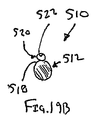
シース520は、例えばシース520の輪郭(または姿勢もしくはプロファイル)を最小にするための収縮した状態(図19Aに示す)から膨張して、拡張した状態(図19Bおよび図19Cに示す)になり得る。拡張した状態において、シース520は少なくとも一部において補助的な内腔522を規定する。補助的な内腔522はシース520の近位端部(図示せず)と遠位端部524との間で延びてよく、その終端はカテーテル512の遠位端部514に隣接することが好ましい。
The
シース520の遠位端部524は、補助的な内腔522と連絡している開口部(図示せず)を含んでよい。別の形態において、遠位端部524は閉じていてよく、また、先に説明した形態と同様に、開口部(図示せず)を形成する分離部分を含んで、内腔522内に挿入される器具(例えば図19Cに示すガイドワイヤ580)が当該開口部から体管腔内に進行するようになっていてよい。
The
必要に応じて、例えば、装置510が患者の体の中を進行させられるときに、シース520を収縮した状態に維持するために、拘束体(図示せず)を設けてよい。例えば、外側シース(図示せず)をカテーテル512およびシース520を収容するために設けてよい。外側シースは、シース520が膨張させられる前に除去され得る。加えて又はこれに代えて、シース520をカテーテル512の外側表面518に沿って一時的に固定するために、接着剤を使用してよい。したがって、接着剤は、図19Aに示すように、シース520をカテーテル512の外側表面518に沿って実質的に平坦に保持し得る。接着剤は、シース520の内腔522内に内部圧力が加えられたときにはずれてよく、あるいは、体管腔内で溶解して、シース520を解放してシース520を膨張させてよい。
If desired, a restraint (not shown) may be provided, for example, to maintain the
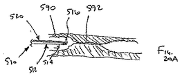
図20A〜20Dを参照して、例えば図18に示す装置510を使用して、器具(例えば、ガイドワイヤ580)を、例えば血管または他の体管腔590内の完全閉塞592を通過するように送る方法を説明する。最初に、図20Aに示すように、シース520が収縮した状態で、装置510を、例えば経皮的な入口サイト(図示せず)を経由させて、カテーテル512の遠位端部514が閉塞592に対して近位側(例えば、上流側)に位置するまで、管590内に導入してよい。
Referring to FIGS. 20A-20D, for example, using the
図20Bを参照して説明すると、カテーテル512の遠位端部514は、シース520の遠位端部524が閉塞592に対して遠位側(例えば、下流側)に位置するまで、閉塞592を貫通させて進行させてよい。カテーテル512は、カテーテル512が閉塞592を貫通して進行するのを容易にするための1または複数のエレメント516を、遠位端部514に含んでよい。例えば、カテーテル512は、閉塞部592を撮像するための撮像エレメント(例えば、IVUSデバイス(図示せず))を遠位端部514にて担持してよい。加えて又はこれに代えて、切開エレメント(例えば、切断、コア、鈍的切開および/または切除(もしくはアブレーション)エレメント(図示せず))を、閉塞を貫通する通路594を形成するために遠位端部514に設けてよい。必要に応じて、カテーテル512は、カテーテル512が閉塞592を貫通して進行するときに、カテーテル512の遠位端部514の操作を容易にするために、ステアリング・エレメント(図示せず)を含んでよい。
With reference to FIG. 20B, the
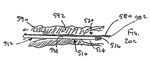
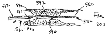
シース520が閉塞592を貫通して延びると、長尺部材(例えばガイドワイヤ580または他の器具(図示せず))を、ガイドワイヤ580の遠位端部582が閉塞592よりも遠位側に位置するまで、シース520内に挿入してよい。シース520は、ガイドワイヤ580または他の器具がシース520内を進行するときに膨張することができる。別法として、シース520は、上述した形態と同様に、例えば、流体をシース520の内腔522(図29B参照)内に導入することによって、展開してよい。
As the
装置510はそれから、閉塞部592を通過させて及び/又は管590の外に、後退させてよい。それから、当業者に周知のように、例えば、閉塞592を治療する及び/または薬剤もしくは流体を閉塞592を越えて送るために1または複数の器具(図示せず)を、ガイドワイヤ592上を進行させてよい。したがって、先の形態とは異なって、シース520は、カテーテル512と協働して送られ得る二次的なデバイス(例えばガイドワイヤ)のための内腔を与え得る。
本発明は、次の態様のものを含む。
(態様1)
患者の体管腔へアクセスする装置であって、
体管腔に挿入するための寸法および形状を有する遠位端部および近位端部を有する可撓性の補強部材;および
補強部材の近位端部と遠位端部との間で延在する膨張可能なシースであって、シースの輪郭を最小にして補強部材とともに管腔に挿入することを許容する収縮した状態から膨張することができ、補強部材の近位端部と遠位端部との間でシースが少なくとも部分的に内腔を規定する拡張した状態になる、シース
を含む装置。
(態様2)
シースがなめらかな材料を含む、態様1の装置。
(態様3)
シースがポリマーを含む態様1の装置。
(態様4)
ポリマーが、PTFE、EPTFE、FEP、PET、ウレタン、オレフィンおよびPEのうち少なくとも1つを含む、態様3の装置。
(態様5)
シースが弾性材料を含む、態様1の装置。
(態様6)
弾性材料が、シリコーン、ラテックス、イソプレンおよびクロノプレンのうち少なくとも1つを含む、態様5の装置。
(態様7)
シースが、補強部材の近位端部と遠位端部との間の1または複数の箇所にて補強部材に取り付けられている管状部材を含む、態様1の装置。
(態様8)
補強部材が、シースに沿って延びる1または複数のストランドを含む、態様7の装置。
(態様9)
前記1または複数のストランドがシースに沿って、軸方向、らせん方向および円周方向のうち少なくとも1つの方向に延びる、態様8の装置。
(態様10)
シースが、シートおよび補強部材がともに内腔を規定するように、先端が補強部材に取り付けられているシート材料を含む、態様1の装置。
(態様11)
シースが、内腔と連絡している開口部を有する遠位端部を含み、内腔を通過して挿入される器具が開口部から体管腔に進行し得るようになっている、態様1の装置。
(態様12)
シースが実質的に閉じた遠位端部を含み、当該遠位端部が開口部を形成するための分離部分を含み、内腔を通過して挿入される器具が開口部から体管腔に進行し得るようになっている、態様1の装置。
(態様13)
分離部分が、シースを構成する材料が弱くされた領域された領域を含む、態様12の装置。
(態様14)
シースが補強部材の遠位端部に取り付けられた実質的に閉じた遠位端部を含み、シースの遠位端部が開口部を形成するように補強部材から分離可能であり、内腔を通過して挿入される器具が開口部から体管腔に進行し得るようになっている、態様1の装置。
(態様15)
シースが裂けるように構成されて、シースが内腔内に配置された器具の周囲から除去され得るようになっている、態様1の装置。
(態様16)
シースがシースの近位端部と遠位端部との間で延びる弱くされた領域を含む、態様15の装置。
(態様17)
シースが、約0.01インチ(0.25mm)以下の壁厚さを有する、態様1の装置。
(態様18)
補強部材が、近位端部を押すことにより捩れる又は歪むおそれがなく遠位端部が体管腔を通過して進行し得るほど十分なコラム強さを有する、態様1の装置。
(態様19)
補強部材がガイドワイヤを含む、態様1の装置。
(態様20)
補強部材が弓形の断面を有し、それにより、近位端部と遠位端部との間で延びるグルーブであって、その内部にて、シースの少なくとも一部が、装置の断面輪郭を最小にする収縮した状態で配置されているグルーブを規定している、態様1の装置。
(態様21)
補強部材が、シースの長手方向の軸に実質的に平行に延びる長尺部材を含む、態様1の装置。
(態様22)
シースが、1または複数の箇所にて、補強部材に取り付けられている、態様1の装置。
(態様23)
シースが補強部材の近位端部と遠位端部に取り付けられている、態様21の装置。
(態様24)
シースが補強部材の遠位端部と近位端部との間で実質的に連続的に補強部材に取り付けられている、態様21の装置。
(態様25)
シースが取り外し可能なように補強部材に固定されている、態様21の装置。
(態様26)
補強部材が、シースの長手方向の軸に実質的に平行に延びる複数の長尺部材を含む、態様1の装置。
(態様27)
シースを収縮した状態に選択的に保持する拘束体をさらに含む、態様1の装置。
(態様28)
拘束体が、その内部に補強部材およびシースが配置され得る内腔を有する管状部材を含む、態様27の装置。
(態様29)
拘束体が、収縮した状態のシースを囲む外側シースを含み、当該外側シースが、シースが拡張した状態に膨張することを許容するように分離可能である1または複数の弱くされた領域を含む、態様27の装置。
(態様30)
外側シースが補強部材の近位端部と遠位端部との間で1または複数の箇所にて補強部材に取り付けられている、態様29の装置。
(態様31)
外側シースが、シースが収縮した状態にて配置され得る内腔を有し、当該内腔が流体をその内部に受け入れるように構成されていて、流体圧力が前記1または複数の弱くされた領域を分離させるようになっている、態様29の装置。
(態様32)
拘束体が膨張可能な部材の周囲に配置される1または複数のストランドを含む、態様27の装置。
(態様33)
拘束体が接着剤および生体吸収可能な封入材料のうち少なくとも1つを含む、態様27の装置。
(態様34)
シースが拡張した状態で近位端部と遠位端部との間で延びる複数の内腔を有する、態様1の装置。
(態様35)
前記複数の内腔の各々が、注入、吸引、潅流および攪拌のうち少なくとも1つのために構成されている、態様34の装置。
(態様36)
患者の体管腔へアクセスする装置であって、膨張可能な薄弱なシースであって、シースが患者の体の中への入口サイトとターゲットとする体管腔との間で延びるのに十分な長さ、近位端部、および遠位端部を含む、シースを含み、
シースが、シースの輪郭を最小にして体管腔への挿入を許容する収縮した状態から膨張可能であり、且つ近位端部と遠位端部との間で延びる内腔を少なくとも部分的に規定する拡張した状態になるものである、装置。
(態様37)
シースがなめらかな材料を含む、態様36の装置。
(態様38)
シースがポリマーを含む、態様36の装置。
(態様39)
シースが弾性材料を含む、態様36の装置。
(態様40)
シースが管状部材を含む、態様36の装置。
(態様41)
シースに沿って延びる1または複数の補強部材をさらに含む、態様36の装置。
(態様42)
1または複数の補強部材がシースに沿って、軸方向、らせん方向および周方向の少なくとも1つの方向に延びる、態様41の装置。
(態様43)
長尺の補強部材をさらに含み、シースが、先端が補強部材に取り付けられているシート材料を含み、シートおよび補強部材がともに内腔を規定するようになっている、態様36の装置。
(態様44)
シースが、内腔と連絡している開口部を有する遠位端部を含み、内腔を通過して挿入された器具が開口部から体管腔内に進行し得るようになっている、態様36の装置。
(態様45)
シースが実質的に閉じた遠位端部を含み、当該遠位端部が開口部を形成するための分離部分を含み、内腔を通過して挿入された器具が開口部から体管腔内に進行し得るようになっている、態様36の装置。
(態様46)
シースが裂けるように構成されていて、シースが内腔内に配置された器具の周囲から除去され得るようになっている、態様36の装置。
(態様47)
シースが約0.01インチ(0.25mm)以下の壁厚さを有する、態様36の装置。
(態様48)
シースを収縮した状態に選択的に維持する拘束体をさらに含む、態様36の装置。
(態様49)
シースの内腔を経由して挿入可能な1または複数の器具をさらに含む、態様36の装置。
(態様50)
患者の体管腔内への搬送装置であって、
近位端部および遠位端部を含む可撓性のカテーテル;
カテーテルの外側表面に取り付けられた膨張可能なシースであって、シースの近位端部と遠位端部との間で延びる内腔を含み、シースの輪郭を最小にする収縮した状態から膨張可能であって、且つシースの近位端部と遠位端部との間で延びる補助的な内腔をシースが少なくとも部分的に規定する拡張した状態になる、シースを含む、装置。
(態様51)
シースがなめらかな材料を含む、態様50の装置。
(態様52)
シースは薄弱な物質を含む、態様50の装置。
(態様53)
シースが実質的に閉じた遠位端部を含み、当該遠位端部が開口部を形成するための分離部分を含み、内腔を通過して挿入された器具が開口部から体管腔内に進行し得るようになっている、態様50の装置。
(態様54)
シースが約0.01インチ(0.25mm)以下の壁厚さを有する、態様50の装置。
(態様55)
シースを収縮した状態に選択的に維持する拘束体をさらに含む、態様50の装置。
The present invention includes the following aspects.
(Aspect 1)
A device for accessing a body lumen of a patient,
A flexible reinforcing member having a distal end and a proximal end having a size and shape for insertion into a body lumen; and extending between the proximal and distal ends of the reinforcing member An expandable sheath that can be expanded from a contracted state that allows insertion into the lumen with the reinforcement member with minimal sheath contour, the proximal and distal ends of the reinforcement member Between which the sheath is in an expanded state at least partially defining a lumen.
(Aspect 2)
The device of
(Aspect 3)
The device of
(Aspect 4)
The apparatus of
(Aspect 5)
The device of
(Aspect 6)
The apparatus of embodiment 5, wherein the elastic material comprises at least one of silicone, latex, isoprene and chronoprene.
(Aspect 7)
The device of
(Aspect 8)
The device of
(Aspect 9)
The apparatus of aspect 8, wherein the one or more strands extend along the sheath in at least one of an axial direction, a helical direction, and a circumferential direction.
(Aspect 10)
The apparatus of
(Aspect 11)
(Aspect 12)
The sheath includes a substantially closed distal end, the distal end including a separation portion for forming an opening, and an instrument inserted through the lumen from the opening into the body lumen The apparatus of
(Aspect 13)
The device of
(Aspect 14)
The sheath includes a substantially closed distal end attached to the distal end of the reinforcing member, the distal end of the sheath being separable from the reinforcing member so as to form an opening, and the lumen The device of
(Aspect 15)
The device of
(Aspect 16)
The device of aspect 15, wherein the sheath includes a weakened region extending between the proximal and distal ends of the sheath.
(Aspect 17)
The device of
(Aspect 18)
The device of
(Aspect 19)
The apparatus of
(Aspect 20)
The reinforcing member has an arcuate cross section, whereby a groove extending between the proximal and distal ends, wherein at least a portion of the sheath minimizes the cross-sectional profile of the device The apparatus of
(Aspect 21)
The device of
(Aspect 22)
The device of
(Aspect 23)
The device of aspect 21, wherein the sheath is attached to the proximal and distal ends of the reinforcing member.
(Aspect 24)
The device of aspect 21, wherein the sheath is attached to the reinforcement member substantially continuously between the distal and proximal ends of the reinforcement member.
(Aspect 25)
The device of aspect 21, wherein the sheath is removably secured to the reinforcing member.
(Aspect 26)
The apparatus of
(Aspect 27)
The device of
(Aspect 28)
The device of aspect 27, wherein the restraint includes a tubular member having a lumen within which the reinforcing member and the sheath can be disposed.
(Aspect 29)
The restraint includes an outer sheath surrounding the sheath in a contracted state, the outer sheath including one or more weakened regions that are separable to allow the sheath to expand to an expanded state; The device of aspect 27.
(Aspect 30)
The device of
(Aspect 31)
The outer sheath has a lumen that can be placed with the sheath contracted, the lumen configured to receive fluid therein, and wherein the fluid pressure is reduced to the one or more weakened regions. The device of
(Aspect 32)
The device of aspect 27, wherein the restraint includes one or more strands disposed about the inflatable member.
(Aspect 33)
The device of aspect 27, wherein the restraint comprises at least one of an adhesive and a bioabsorbable encapsulant.
(Aspect 34)
The device of
(Aspect 35)
The device of aspect 34, wherein each of the plurality of lumens is configured for at least one of infusion, aspiration, perfusion and agitation.
(Aspect 36)
An apparatus for accessing a body lumen of a patient, an inflatable, thin sheath sufficient to extend between an entrance site into the patient's body and a target body lumen A sheath including a length, a proximal end, and a distal end;
The sheath is inflatable from a contracted state that allows insertion into a body lumen with minimal sheath contour, and at least partially includes a lumen extending between the proximal and distal ends A device that is in an expanded state that prescribes.
(Aspect 37)
The device of embodiment 36, wherein the sheath comprises a smooth material.
(Aspect 38)
The device of embodiment 36, wherein the sheath comprises a polymer.
(Aspect 39)
The device of embodiment 36, wherein the sheath comprises an elastic material.
(Aspect 40)
The device of embodiment 36, wherein the sheath comprises a tubular member.
(Aspect 41)
The device of aspect 36, further comprising one or more reinforcing members extending along the sheath.
(Aspect 42)
The device of aspect 41, wherein the one or more reinforcing members extend along the sheath in at least one of an axial direction, a helical direction, and a circumferential direction.
(Aspect 43)
The device of aspect 36, further comprising an elongate reinforcing member, wherein the sheath includes sheet material having a distal end attached to the reinforcing member, wherein the sheet and the reinforcing member together define a lumen.
(Aspect 44)
An embodiment wherein the sheath includes a distal end having an opening in communication with the lumen, such that an instrument inserted through the lumen can be advanced from the opening into the body lumen 36 devices.
(Aspect 45)
The sheath includes a substantially closed distal end, the distal end including a separation portion for forming an opening, and an instrument inserted through the lumen is inserted into the body lumen from the opening. 38. The apparatus of aspect 36, wherein the apparatus is capable of proceeding to
(Aspect 46)
The device of aspect 36, wherein the sheath is configured to tear so that the sheath can be removed from around the instrument disposed within the lumen.
(Aspect 47)
The device of embodiment 36, wherein the sheath has a wall thickness of about 0.01 inches (0.25 mm) or less.
(Aspect 48)
The device of aspect 36, further comprising a restraint that selectively maintains the sheath in a contracted state.
(Aspect 49)
The device of aspect 36, further comprising one or more instruments insertable through the lumen of the sheath.
(Aspect 50)
A delivery device into a patient's body lumen,
A flexible catheter including a proximal end and a distal end;
An inflatable sheath attached to the outer surface of the catheter, including a lumen extending between the proximal and distal ends of the sheath and inflatable from a contracted state that minimizes the sheath profile A device comprising a sheath, wherein the sheath is in an expanded state defining at least partially an auxiliary lumen extending between the proximal and distal ends of the sheath.
(Aspect 51)
The device of embodiment 50, wherein the sheath comprises a smooth material.
(Aspect 52)
The device of embodiment 50, wherein the sheath comprises a weak material.
(Aspect 53)
The sheath includes a substantially closed distal end, the distal end including a separation portion for forming an opening, and an instrument inserted through the lumen is inserted into the body lumen from the opening. The device of aspect 50, wherein the device is capable of proceeding to
(Aspect 54)
The device of aspect 50, wherein the sheath has a wall thickness of about 0.01 inches (0.25 mm) or less.
(Aspect 55)
The device of aspect 50, further comprising a restraint that selectively maintains the sheath in a contracted state.
本発明は、種々の変形例および代替的な形態を取りうるが、特定の例を図面において示し、明細書において詳細に説明した。しかしながら、本発明は開示された特定の形態又は方法に限定されるべきではなく、本発明は添付した請求の範囲の精神および範囲内にあるすべての変形例、等価物、および代替物に及ぶべきであることが理解されるべきである。 While the invention is susceptible to various modifications and alternative forms, specific examples have been shown in the drawings and have been described in detail in the specification. However, the invention should not be limited to the particular forms or methods disclosed, but the invention should cover all modifications, equivalents, and alternatives that are within the spirit and scope of the appended claims. It should be understood that
Claims (12)
体管腔に挿入するための寸法および形状を有する遠位端部および近位端部を有する可撓性の補強部材であって、遠位端部と近位端部との間で延在する1または複数の内腔を有する補強部材;および
補強部材の近位端部と遠位端部に取り付けられ、かつ近位端部と遠位端部との間で延在する膨張可能なシースであって、シースの輪郭を最小にして補強部材とともに体管腔に挿入することを許容する収縮した状態から膨張することができ、補強部材の近位端部と遠位端部との間でシースが少なくとも部分的に内腔を規定する拡張した状態になる、シース
を含み、
補強部材が、膨張可能なシースの遠位端部を越えて延びる実質的に非外傷性の遠位先端を有する、
装置。 A device for accessing a body lumen of a patient,
A flexible stiffening member having a distal end and a proximal end having a size and shape for insertion into a body lumen, the extension member extending between the distal end and the proximal end A reinforcing member having one or more lumens; and an inflatable sheath attached to the proximal and distal ends of the reinforcing member and extending between the proximal and distal ends A sheath between a proximal end and a distal end of the reinforcing member that can be inflated from a contracted state that allows insertion into the body lumen with the reinforcing member with minimal sheath contour Including a sheath, which is in an expanded state at least partially defining the lumen;
The reinforcing member has a substantially atraumatic distal tip extending beyond the distal end of the inflatable sheath;
apparatus.
体管腔に挿入するための寸法および形状を有する遠位端部および近位端部を有する可撓性の補強部材であって、遠位端部と近位端部との間で延在する1または複数の内腔を有する補強部材;および
補強部材の近位端部と遠位端部に取り付けられ、かつ近位端部と遠位端部との間で延在する、薄弱かつ膨張可能なシースであって、シースの輪郭を最小にして補強部材とともに体管腔に挿入することを許容する収縮した状態から膨張することができ、補強部材の近位端部と遠位端部との間でシースが少なくとも部分的に内腔を規定する拡張した状態になる、シース
を含み、
補強部材が、シースの近位端部と遠位端部との間で延びるシースの独立したポケットまたは内腔に収容されている、
装置。 A device for accessing a body lumen of a patient,
A flexible stiffening member having a distal end and a proximal end having a size and shape for insertion into a body lumen, the extension member extending between the distal end and the proximal end A reinforcing member having one or more lumens; and a weak and inflatable attached to the proximal and distal ends of the reinforcing member and extending between the proximal and distal ends A sheath that can be expanded from a contracted state that allows insertion into a body lumen with a reinforcing member with minimal sheath contour, and the proximal and distal ends of the reinforcing member Including a sheath between which the sheath becomes expanded, at least partially defining a lumen;
A reinforcing member is housed in a separate pocket or lumen of the sheath extending between the proximal and distal ends of the sheath;
apparatus.
体管腔に挿入するための寸法および形状を有する遠位端部および近位端部を有する可撓性の補強部材;
補強部材の近位端部と遠位端部との間で延在する膨張可能なシースであって、シースの輪郭を最小にして補強部材とともに体管腔に挿入することを許容する収縮した状態から膨張することができ、補強部材の近位端部と遠位端部との間でシースが少なくとも部分的に内腔を規定する拡張した状態になる、シース;および
シースが補強部材とともに進行させられて患者の所望の体管腔内に達した後に、シースの内腔を通って進行しうる、電気リード
を含む、システム。 A system for treating a patient via a body lumen,
A flexible reinforcement member having a distal end and a proximal end having dimensions and shape for insertion into a body lumen;
An inflatable sheath extending between the proximal and distal ends of the reinforcement member, wherein the sheath is in a contracted state that allows insertion into the body lumen with the reinforcement member with minimal sheath contour Between the proximal end and the distal end of the reinforcement member, the sheath at least partially defining a lumen, wherein the sheath is advanced with the reinforcement member; A system that includes an electrical lead that can be advanced through the lumen of the sheath after being delivered into the desired body lumen of the patient.
Applications Claiming Priority (4)
| Application Number | Priority Date | Filing Date | Title |
|---|---|---|---|
| US37606502P | 2002-04-25 | 2002-04-25 | |
| US60/376,065 | 2002-04-25 | ||
| US10/423,321 US7762995B2 (en) | 2002-04-25 | 2003-04-24 | Expandable guide sheath and apparatus and methods using such sheaths |
| US10/423,321 | 2003-04-24 |
Related Parent Applications (1)
| Application Number | Title | Priority Date | Filing Date |
|---|---|---|---|
| JP2003587459A Division JP4583032B2 (en) | 2002-04-25 | 2003-04-24 | Inflatable guide sheath and apparatus and method using the sheath |
Publications (2)
| Publication Number | Publication Date |
|---|---|
| JP2010188198A true JP2010188198A (en) | 2010-09-02 |
| JP5487015B2 JP5487015B2 (en) | 2014-05-07 |
Family
ID=29273046
Family Applications (2)
| Application Number | Title | Priority Date | Filing Date |
|---|---|---|---|
| JP2003587459A Expired - Lifetime JP4583032B2 (en) | 2002-04-25 | 2003-04-24 | Inflatable guide sheath and apparatus and method using the sheath |
| JP2010132478A Expired - Lifetime JP5487015B2 (en) | 2002-04-25 | 2010-06-09 | Inflatable guide sheath and apparatus and method using the sheath |
Family Applications Before (1)
| Application Number | Title | Priority Date | Filing Date |
|---|---|---|---|
| JP2003587459A Expired - Lifetime JP4583032B2 (en) | 2002-04-25 | 2003-04-24 | Inflatable guide sheath and apparatus and method using the sheath |
Country Status (7)
| Country | Link |
|---|---|
| US (2) | US7762995B2 (en) |
| EP (2) | EP2067499B1 (en) |
| JP (2) | JP4583032B2 (en) |
| AT (1) | ATE427768T1 (en) |
| AU (1) | AU2003223749A1 (en) |
| DE (1) | DE60327067D1 (en) |
| WO (1) | WO2003090834A2 (en) |
Cited By (1)
| Publication number | Priority date | Publication date | Assignee | Title |
|---|---|---|---|---|
| JP2016505309A (en) * | 2012-12-18 | 2016-02-25 | コーニンクレッカ フィリップス エヌ ヴェKoninklijke Philips N.V. | Reusable MR safe temperature probe for surface and body temperature measurement |
Families Citing this family (261)
| Publication number | Priority date | Publication date | Assignee | Title |
|---|---|---|---|---|
| US6306166B1 (en) * | 1997-08-13 | 2001-10-23 | Scimed Life Systems, Inc. | Loading and release of water-insoluble drugs |
| US20030088240A1 (en) * | 2001-11-02 | 2003-05-08 | Vahid Saadat | Methods and apparatus for cryo-therapy |
| AU2003223749A1 (en) | 2002-04-25 | 2003-11-10 | The Board Of Trustees Of The Leland Stanford Junior University | Expandable guide sheath and apparatus and methods using such sheaths |
| US8956280B2 (en) | 2002-05-30 | 2015-02-17 | Intuitive Surgical Operations, Inc. | Apparatus and methods for placing leads using direct visualization |
| US6793678B2 (en) | 2002-06-27 | 2004-09-21 | Depuy Acromed, Inc. | Prosthetic intervertebral motion disc having dampening |
| US7309334B2 (en) | 2002-07-23 | 2007-12-18 | Von Hoffmann Gerard | Intracranial aspiration catheter |
| US8425549B2 (en) | 2002-07-23 | 2013-04-23 | Reverse Medical Corporation | Systems and methods for removing obstructive matter from body lumens and treating vascular defects |
| US7591832B2 (en) * | 2003-04-24 | 2009-09-22 | Medtronic, Inc. | Expandable guide sheath and apparatus with distal protection and methods for use |
| US8388628B2 (en) * | 2003-04-24 | 2013-03-05 | Medtronic, Inc. | Expandable sheath for delivering instruments and agents into a body lumen and methods for use |
| US7909766B2 (en) * | 2003-05-21 | 2011-03-22 | Scimed Life Systems, Inc. | Systems and methods for improving the imaging resolution of an imaging transducer |
| WO2005032642A2 (en) * | 2003-10-03 | 2005-04-14 | Acumen Medical, Inc. | Expandable guide sheath and apparatus and methods for making them |
| US9241735B2 (en) * | 2003-12-05 | 2016-01-26 | Onset Medical Corporation | Expandable percutaneous sheath |
| US7780692B2 (en) | 2003-12-05 | 2010-08-24 | Onset Medical Corporation | Expandable percutaneous sheath |
| ATE468830T1 (en) * | 2004-03-31 | 2010-06-15 | Wilson Cook Medical Inc | STENT DELIVERY SYSTEM |
| US20050245984A1 (en) * | 2004-04-30 | 2005-11-03 | Medtronic, Inc. | Implantable medical device with lubricious material |
| US7422559B2 (en) | 2004-06-16 | 2008-09-09 | Ge Inspection Technologies, Lp | Borescope comprising fluid supply system |
| US9387313B2 (en) * | 2004-08-03 | 2016-07-12 | Interventional Spine, Inc. | Telescopic percutaneous tissue dilation systems and related methods |
| US20060030872A1 (en) * | 2004-08-03 | 2006-02-09 | Brad Culbert | Dilation introducer for orthopedic surgery |
| US7892203B2 (en) | 2004-09-09 | 2011-02-22 | Onset Medical Corporation | Expandable transluminal sheath |
| US20060135962A1 (en) | 2004-09-09 | 2006-06-22 | Kick George F | Expandable trans-septal sheath |
| US7993350B2 (en) * | 2004-10-04 | 2011-08-09 | Medtronic, Inc. | Shapeable or steerable guide sheaths and methods for making and using them |
| US7875049B2 (en) * | 2004-10-04 | 2011-01-25 | Medtronic, Inc. | Expandable guide sheath with steerable backbone and methods for making and using them |
| US8872906B2 (en) | 2005-01-05 | 2014-10-28 | Avantis Medical Systems, Inc. | Endoscope assembly with a polarizing filter |
| US8182422B2 (en) | 2005-12-13 | 2012-05-22 | Avantis Medical Systems, Inc. | Endoscope having detachable imaging device and method of using |
| US8289381B2 (en) | 2005-01-05 | 2012-10-16 | Avantis Medical Systems, Inc. | Endoscope with an imaging catheter assembly and method of configuring an endoscope |
| US8797392B2 (en) | 2005-01-05 | 2014-08-05 | Avantis Medical Sytems, Inc. | Endoscope assembly with a polarizing filter |
| US20060184105A1 (en) * | 2005-02-15 | 2006-08-17 | Townsend Gregory L | Thin wall catheter and method of placing same |
| WO2006122061A1 (en) * | 2005-05-06 | 2006-11-16 | Acumen Medical, Inc. | Complexly shaped steerable catheters and methods for making and using them |
| US8092481B2 (en) | 2005-06-03 | 2012-01-10 | Onset Medical Corporation | Expandable percutaneous sheath |
| US8801744B2 (en) * | 2006-06-28 | 2014-08-12 | Abbott Laboratories | Expandable introducer sheath to preserve guidewire access |
| US20080004571A1 (en) * | 2006-06-28 | 2008-01-03 | Abbott Laboratories | Expandable introducer sheath |
| US9168359B2 (en) | 2005-06-30 | 2015-10-27 | Abbott Laboratories | Modular introducer and exchange sheath |
| US8440122B2 (en) | 2005-06-30 | 2013-05-14 | Abbott Vascular Inc. | Introducer sheath and methods of making |
| US9352118B2 (en) * | 2005-06-30 | 2016-05-31 | Abbott Laboratories | Modular introducer and exchange sheath |
| US20100130937A1 (en) * | 2005-06-30 | 2010-05-27 | Abbott Vascular Inc. | Introducer sheath and methods of making |
| US8359723B2 (en) | 2005-06-30 | 2013-01-29 | Abbott Vascular Inc. | Introducer sheath and methods of making |
| US9597063B2 (en) * | 2006-06-28 | 2017-03-21 | Abbott Laboratories | Expandable introducer sheath to preserve guidewire access |
| US7575569B2 (en) * | 2005-08-16 | 2009-08-18 | Medtronic, Inc. | Apparatus and methods for delivering stem cells and other agents into cardiac tissue |
| US7765014B2 (en) | 2005-08-16 | 2010-07-27 | Medtronic, Inc. | Apparatus and methods for delivering transvenous leads |
| US7556710B2 (en) * | 2005-10-04 | 2009-07-07 | Ilh, Llc | Catheters with lubricious linings and methods for making and using them |
| WO2009114556A2 (en) * | 2005-10-04 | 2009-09-17 | Ilh, Llc | Catheters with lubricious linings and methods for making and using them |
| US7553387B2 (en) | 2005-10-04 | 2009-06-30 | Ilh, Llc | Catheters with lubricious linings and methods for making and using them |
| US9974887B2 (en) | 2005-10-04 | 2018-05-22 | Clph, Llc | Catheters with lubricious linings and methods for making and using them |
| US7550053B2 (en) * | 2006-01-26 | 2009-06-23 | Ilh, Llc | Catheters with lubricious linings and methods for making and using them |
| US20070088296A1 (en) * | 2005-10-04 | 2007-04-19 | Leeflang Stephen A | Catheters with lubricious linings and methods for making and using them |
| US7637902B2 (en) | 2005-11-23 | 2009-12-29 | Medtronic, Inc. | Slittable and peelable sheaths and methods for making and using them |
| WO2007087421A2 (en) | 2006-01-23 | 2007-08-02 | Avantis Medical Systems, Inc. | Endoscope |
| US20070185444A1 (en) * | 2006-02-03 | 2007-08-09 | Starfire Medical, Inc. | Vascular clip-on occlusion system |
| US20070185457A1 (en) * | 2006-02-03 | 2007-08-09 | Starfire Medical, Inc. | Vascular occlusion delivery |
| US20070185442A1 (en) * | 2006-02-03 | 2007-08-09 | Starfire Medical, Inc. | Rapid balloon coupling system |
| US20070185443A1 (en) * | 2006-02-03 | 2007-08-09 | Starfire Medical, Inc. | Vascular therapy delivery system |
| US8287446B2 (en) | 2006-04-18 | 2012-10-16 | Avantis Medical Systems, Inc. | Vibratory device, endoscope having such a device, method for configuring an endoscope, and method of reducing looping of an endoscope |
| US9084901B2 (en) | 2006-04-28 | 2015-07-21 | Medtronic, Inc. | Cranial implant |
| JP2009537283A (en) | 2006-05-19 | 2009-10-29 | アヴァンティス メディカル システムズ インコーポレイテッド | Apparatus and method for reducing the effects of video artifacts |
| US9889275B2 (en) | 2006-06-28 | 2018-02-13 | Abbott Laboratories | Expandable introducer sheath to preserve guidewire access |
| US20100198160A1 (en) * | 2006-06-28 | 2010-08-05 | Abbott Vascular Inc. | Expandable Introducer Sheaths and Methods for Manufacture and Use |
| US20080033396A1 (en) * | 2006-08-01 | 2008-02-07 | Percutaneous Systems, Inc. | Vascular sheaths and methods for their deployment |
| US7927272B2 (en) | 2006-08-04 | 2011-04-19 | Avantis Medical Systems, Inc. | Surgical port with embedded imaging device |
| CA2976839C (en) * | 2006-09-08 | 2020-04-28 | Edwards Lifesciences Corporation | Integrated heart valve delivery system |
| US8105382B2 (en) | 2006-12-07 | 2012-01-31 | Interventional Spine, Inc. | Intervertebral implant |
| WO2008079828A2 (en) | 2006-12-20 | 2008-07-03 | Onset Medical Corporation | Expandable trans-septal sheath |
| CA2673991C (en) | 2007-01-21 | 2012-02-07 | Hemoteq Ag | Methods for coating catheter balloons with a defined quantity of active agent |
| US7722568B2 (en) | 2007-01-29 | 2010-05-25 | Onset Medical Corporation | Expandable intra-aortic balloon pump sheath |
| US7686783B2 (en) | 2007-03-30 | 2010-03-30 | Boston Scientific Scimed, Inc. | Perfusion and embolic protection |
| US7780630B2 (en) * | 2007-03-30 | 2010-08-24 | Boston Scientific Scimed, Inc. | Perfusion device |
| WO2008121710A1 (en) * | 2007-03-30 | 2008-10-09 | Boston Scientific Scimed, Inc. | Catheter for perfusion and embolic protection |
| WO2008121888A1 (en) | 2007-03-30 | 2008-10-09 | Onset Medical Corporation | Expandable trans-septal sheath |
| US8064666B2 (en) | 2007-04-10 | 2011-11-22 | Avantis Medical Systems, Inc. | Method and device for examining or imaging an interior surface of a cavity |
| US8900307B2 (en) | 2007-06-26 | 2014-12-02 | DePuy Synthes Products, LLC | Highly lordosed fusion cage |
| US9192697B2 (en) | 2007-07-03 | 2015-11-24 | Hemoteq Ag | Balloon catheter for treating stenosis of body passages and for preventing threatening restenosis |
| US8075575B2 (en) | 2007-08-14 | 2011-12-13 | Toby Orthopaedics, Llc | Device and method for assisting in flexor tendon repair and rehabilitation |
| WO2009046164A1 (en) | 2007-10-05 | 2009-04-09 | Tyco Healthcare Group Lp | Seal anchor for use in surgical procedures |
| US8673100B2 (en) * | 2007-10-19 | 2014-03-18 | Stephen A. Leeflang | Strip lined catheters and methods for constructing and processing strip lined catheters |
| EP2471493A1 (en) | 2008-01-17 | 2012-07-04 | Synthes GmbH | An expandable intervertebral implant and associated method of manufacturing the same |
| US8109908B1 (en) | 2008-01-22 | 2012-02-07 | Greatbatch Ltd. | Biodegradable shroud for a dilator/sheath assembly |
| CN102036623A (en) | 2008-04-05 | 2011-04-27 | 斯恩蒂斯有限公司 | Expandable intervertebral implant |
| US20090259283A1 (en) * | 2008-04-09 | 2009-10-15 | Brandt Michael S | Sheathed lead for pacing or defibrillation |
| US8668668B2 (en) | 2008-05-14 | 2014-03-11 | Onset Medical Corporation | Expandable iliac sheath and method of use |
| US8562559B2 (en) | 2008-05-14 | 2013-10-22 | Onset Medical Corporation | Expandable iliac sheath and method of use |
| FR2932979B1 (en) * | 2008-06-25 | 2012-04-06 | Perouse Lab | INTRODUCING DEVICE EXTENDING BETWEEN A PROXIMAL POINT AND A DISTAL POINT AND NECESSARY FOR TREATMENT THEREOF. |
| US8403889B2 (en) | 2008-06-25 | 2013-03-26 | Covidien Lp | Access assembly |
| KR20160049027A (en) * | 2008-08-28 | 2016-05-04 | 마르코 안토니오 페나 듀크 | Directional expansion of intraluminal devices |
| US8403896B2 (en) * | 2008-08-29 | 2013-03-26 | AUST Development, LLC | Apparatus and methods for making coated liners and tubular devices including such liners |
| USD738500S1 (en) | 2008-10-02 | 2015-09-08 | Covidien Lp | Seal anchor for use in surgical procedures |
| US8790387B2 (en) | 2008-10-10 | 2014-07-29 | Edwards Lifesciences Corporation | Expandable sheath for introducing an endovascular delivery device into a body |
| US7951110B2 (en) | 2008-11-10 | 2011-05-31 | Onset Medical Corporation | Expandable spinal sheath and method of use |
| US9468364B2 (en) | 2008-11-14 | 2016-10-18 | Intuitive Surgical Operations, Inc. | Intravascular catheter with hood and image processing systems |
| US8992558B2 (en) | 2008-12-18 | 2015-03-31 | Osteomed, Llc | Lateral access system for the lumbar spine |
| US8758847B2 (en) * | 2009-02-18 | 2014-06-24 | AUST Development, LLC | Apparatus and methods for making coated liners and tubular devices including such liners |
| US8845582B2 (en) | 2009-03-09 | 2014-09-30 | Flip Technologies Limited | Device for protecting a catheter, and a method for locating a catheter in a remote location in a human or animal body |
| US9526620B2 (en) | 2009-03-30 | 2016-12-27 | DePuy Synthes Products, Inc. | Zero profile spinal fusion cage |
| ES2550634T3 (en) | 2009-07-10 | 2015-11-11 | Boston Scientific Scimed, Inc. | Use of nanocrystals for a drug delivery balloon |
| EP2453938B1 (en) | 2009-07-17 | 2015-08-19 | Boston Scientific Scimed, Inc. | Nucleation of drug delivery balloons to provide improved crystal size and density |
| US20110082370A1 (en) * | 2009-10-02 | 2011-04-07 | Wilson-Cook Medical Inc. | Endoscopic fascia tunneling |
| US9539081B2 (en) | 2009-12-02 | 2017-01-10 | Surefire Medical, Inc. | Method of operating a microvalve protection device |
| US9393129B2 (en) | 2009-12-10 | 2016-07-19 | DePuy Synthes Products, Inc. | Bellows-like expandable interbody fusion cage |
| US20110152917A1 (en) * | 2009-12-22 | 2011-06-23 | Boston Scientific Scimed, Inc. | Intravascular filter restraining device |
| US20110160645A1 (en) * | 2009-12-31 | 2011-06-30 | Boston Scientific Scimed, Inc. | Cryo Activated Drug Delivery and Cutting Balloons |
| US8556896B2 (en) * | 2010-01-27 | 2013-10-15 | Zimmer, Inc. | Distal relief for a surgical device |
| US8728162B2 (en) | 2010-04-15 | 2014-05-20 | Osteomed, Llc | Direct lateral spine system instruments, implants and associated methods |
| US20110282353A1 (en) * | 2010-05-11 | 2011-11-17 | Mchugo Vincent | Biliary access sheath |
| US8979860B2 (en) | 2010-06-24 | 2015-03-17 | DePuy Synthes Products. LLC | Enhanced cage insertion device |
| US9282979B2 (en) | 2010-06-24 | 2016-03-15 | DePuy Synthes Products, Inc. | Instruments and methods for non-parallel disc space preparation |
| AU2011271465B2 (en) | 2010-06-29 | 2015-03-19 | Synthes Gmbh | Distractible intervertebral implant |
| AU2011272764B2 (en) * | 2010-06-30 | 2015-11-19 | Muffin Incorporated | Percutaneous, ultrasound-guided introduction of medical devices |
| US10390889B2 (en) * | 2010-07-26 | 2019-08-27 | St Jude Medical International Holding S.Á R.L. | Removable navigation system and method for a medical device |
| US8889211B2 (en) | 2010-09-02 | 2014-11-18 | Boston Scientific Scimed, Inc. | Coating process for drug delivery balloons using heat-induced rewrap memory |
| US20120071975A1 (en) * | 2010-09-10 | 2012-03-22 | Eduardo Gonzalez-Hernandez | Device and method for assisting in flexor tendon repair and rehabilitation |
| US9402732B2 (en) | 2010-10-11 | 2016-08-02 | DePuy Synthes Products, Inc. | Expandable interspinous process spacer implant |
| US9414944B2 (en) * | 2010-11-11 | 2016-08-16 | W. L. Gore & Associates, Inc. | Deployment sleeve shortening mechanism |
| US9675487B2 (en) * | 2010-11-17 | 2017-06-13 | Cook Medical Technologies Llc | Prosthesis deployment system for vascular repair |
| EP2455018B1 (en) * | 2010-11-22 | 2014-05-21 | Karl Storz GmbH & Co. KG | Trocar sheath for insertion into a skin incision |
| US8948848B2 (en) | 2011-01-07 | 2015-02-03 | Innovative Cardiovascular Solutions, Llc | Angiography catheter |
| KR20140008446A (en) * | 2011-05-06 | 2014-01-21 | 더블유.엘. 고어 앤드 어소시에이트스, 인코포레이티드 | Echogenic sleeve |
| DE102011050173A1 (en) * | 2011-05-06 | 2012-11-08 | Vilmos Nagy | Stretchable introducer sheath and lock system |
| WO2013022458A1 (en) | 2011-08-05 | 2013-02-14 | Boston Scientific Scimed, Inc. | Methods of converting amorphous drug substance into crystalline form |
| US10213329B2 (en) * | 2011-08-12 | 2019-02-26 | W. L. Gore & Associates, Inc. | Evertable sheath devices, systems, and methods |
| WO2013028208A1 (en) | 2011-08-25 | 2013-02-28 | Boston Scientific Scimed, Inc. | Medical device with crystalline drug coating |
| US10238837B2 (en) | 2011-10-14 | 2019-03-26 | Intuitive Surgical Operations, Inc. | Catheters with control modes for interchangeable probes |
| US9452276B2 (en) | 2011-10-14 | 2016-09-27 | Intuitive Surgical Operations, Inc. | Catheter with removable vision probe |
| WO2013060740A1 (en) * | 2011-10-28 | 2013-05-02 | Advant Medical Limited | Protection device for a prostheses and/or balloon catheter and method making and using the same |
| US11213318B2 (en) | 2011-11-10 | 2022-01-04 | Medtronic Vascular, Inc. | Expandable introducer sheath and method |
| CA3082091C (en) | 2011-11-10 | 2023-01-31 | Transaortic Medical, Inc. | System for deploying a device to a distal location across a diseased vessel |
| US20130338677A1 (en) * | 2012-06-18 | 2013-12-19 | Biotronik Ag | Insertion element and insertion device |
| US9283072B2 (en) | 2012-07-25 | 2016-03-15 | W. L. Gore & Associates, Inc. | Everting transcatheter valve and methods |
| WO2014018098A1 (en) | 2012-07-26 | 2014-01-30 | DePuy Synthes Products, LLC | Expandable implant |
| US10376360B2 (en) | 2012-07-27 | 2019-08-13 | W. L. Gore & Associates, Inc. | Multi-frame prosthetic valve apparatus and methods |
| US20140067069A1 (en) | 2012-08-30 | 2014-03-06 | Interventional Spine, Inc. | Artificial disc |
| US9192751B2 (en) | 2012-10-26 | 2015-11-24 | Medtronic, Inc. | Elastic introducer sheath |
| US9907931B2 (en) | 2012-10-26 | 2018-03-06 | Medtronic, Inc. | Elastic introducer sheath |
| AU2013337807B2 (en) | 2012-11-01 | 2016-12-08 | Muffin Incorporated | Implements for identifying sheath migration |
| US9414752B2 (en) | 2012-11-09 | 2016-08-16 | Elwha Llc | Embolism deflector |
| US9737398B2 (en) | 2012-12-19 | 2017-08-22 | W. L. Gore & Associates, Inc. | Prosthetic valves, frames and leaflets and methods thereof |
| US10039638B2 (en) | 2012-12-19 | 2018-08-07 | W. L. Gore & Associates, Inc. | Geometric prosthetic heart valves |
| US10966820B2 (en) | 2012-12-19 | 2021-04-06 | W. L. Gore & Associates, Inc. | Geometric control of bending character in prosthetic heart valve leaflets |
| US9144492B2 (en) | 2012-12-19 | 2015-09-29 | W. L. Gore & Associates, Inc. | Truncated leaflet for prosthetic heart valves, preformed valve |
| US9101469B2 (en) | 2012-12-19 | 2015-08-11 | W. L. Gore & Associates, Inc. | Prosthetic heart valve with leaflet shelving |
| US10321986B2 (en) | 2012-12-19 | 2019-06-18 | W. L. Gore & Associates, Inc. | Multi-frame prosthetic heart valve |
| US9968443B2 (en) | 2012-12-19 | 2018-05-15 | W. L. Gore & Associates, Inc. | Vertical coaptation zone in a planar portion of prosthetic heart valve leaflet |
| BR112015013364B1 (en) * | 2012-12-31 | 2021-04-20 | Clearstream Technologies Limited | apparatus for treating a treatment area in a vasculature and method of assembling a set that includes a catheter that includes a balloon |
| US20140228661A1 (en) * | 2013-02-08 | 2014-08-14 | Liviu Popa-Simil | Biopsy method and gun set devices |
| US20140228814A1 (en) * | 2013-02-09 | 2014-08-14 | Boston Scientific Scimed, Inc. | Expandable sheath |
| US9717601B2 (en) | 2013-02-28 | 2017-08-01 | DePuy Synthes Products, Inc. | Expandable intervertebral implant, system, kit and method |
| US9522070B2 (en) | 2013-03-07 | 2016-12-20 | Interventional Spine, Inc. | Intervertebral implant |
| US9539411B2 (en) * | 2013-03-13 | 2017-01-10 | W. L. Gore & Associates, Inc. | Deconstructable endoluminal devices and related systems and methods |
| US20140276905A1 (en) * | 2013-03-18 | 2014-09-18 | Biotronik Ag | Insertion Element and Insertion Device |
| AU2014262488B2 (en) * | 2013-05-10 | 2018-08-30 | Medtronic, Inc. | System for deploying a device to a distal location across a diseased vessel |
| CA2912204A1 (en) | 2013-05-17 | 2014-11-20 | Transaortic Medical, Inc. | Expandable introducer sheath |
| US9629978B2 (en) | 2013-05-20 | 2017-04-25 | Clph, Llc | Catheters with intermediate layers and methods for making them |
| US10434307B2 (en) | 2013-10-15 | 2019-10-08 | Medtronic, Inc. | Methods and devices for subcutaneous lead implantation |
| US9610436B2 (en) | 2013-11-12 | 2017-04-04 | Medtronic, Inc. | Implant tools with attachment feature and multi-positional sheath and implant techniques utilizing such tools |
| US10792490B2 (en) | 2013-11-12 | 2020-10-06 | Medtronic, Inc. | Open channel implant tools and implant techniques utilizing such tools |
| US10966850B2 (en) | 2014-03-06 | 2021-04-06 | W. L. Gore & Associates, Inc. | Implantable medical device constraint and deployment apparatus |
| US9968740B2 (en) | 2014-03-25 | 2018-05-15 | Surefire Medical, Inc. | Closed tip dynamic microvalve protection device |
| JP2016005547A (en) * | 2014-05-27 | 2016-01-14 | 公立大学法人横浜市立大学 | Wire for detecting lymphatic vessel position |
| GB201411486D0 (en) * | 2014-06-27 | 2014-08-13 | Isis Innovation | Apparatus for providing and maintaining access to a surgical site |
| US10064649B2 (en) | 2014-07-07 | 2018-09-04 | Covidien Lp | Pleated seal for surgical hand or instrument access |
| CN106659567B (en) | 2014-08-18 | 2019-06-14 | W.L.戈尔及同仁股份有限公司 | Frame with integral suture cuff for prosthetic valve |
| US9827094B2 (en) | 2014-09-15 | 2017-11-28 | W. L. Gore & Associates, Inc. | Prosthetic heart valve with retention elements |
| US10569063B2 (en) | 2014-10-03 | 2020-02-25 | W. L. Gore & Associates, Inc. | Removable covers for drug eluting medical devices |
| WO2016064449A1 (en) | 2014-10-20 | 2016-04-28 | Research Development International Corporation | Steerable micro-endoscope |
| US9707011B2 (en) | 2014-11-12 | 2017-07-18 | Covidien Lp | Attachments for use with a surgical access device |
| US11083491B2 (en) | 2014-12-09 | 2021-08-10 | Medtronic, Inc. | Extravascular implant tools utilizing a bore-in mechanism and implant techniques using such tools |
| US10349978B2 (en) | 2014-12-18 | 2019-07-16 | Medtronic, Inc. | Open channel implant tool with additional lumen and implant techniques utilizing such tools |
| US11426290B2 (en) | 2015-03-06 | 2022-08-30 | DePuy Synthes Products, Inc. | Expandable intervertebral implant, system, kit and method |
| US20160287839A1 (en) | 2015-03-31 | 2016-10-06 | Surefire Medical, Inc. | Apparatus and Method for Infusing an Immunotherapy Agent to a Solid Tumor for Treatment |
| US10327896B2 (en) | 2015-04-10 | 2019-06-25 | Edwards Lifesciences Corporation | Expandable sheath with elastomeric cross sectional portions |
| US10792471B2 (en) | 2015-04-10 | 2020-10-06 | Edwards Lifesciences Corporation | Expandable sheath |
| US12194256B2 (en) | 2015-04-10 | 2025-01-14 | Edwards Lifesciences Corporation | Expandable sheath |
| US9913727B2 (en) | 2015-07-02 | 2018-03-13 | Medos International Sarl | Expandable implant |
| US20170189059A1 (en) * | 2016-01-06 | 2017-07-06 | Boston Scientific Scimed, Inc. | Percutaneous access device |
| US10548631B2 (en) | 2016-03-04 | 2020-02-04 | Boston Scientific Scimed Inc. | Introducer with expandable capabilities |
| US10940294B2 (en) * | 2016-04-25 | 2021-03-09 | Medtronic Vascular, Inc. | Balloon catheter including a drug delivery sheath |
| EP3474783B1 (en) | 2016-06-28 | 2023-05-03 | Eit Emerging Implant Technologies GmbH | Expandable, angularly adjustable intervertebral cages |
| WO2018002715A2 (en) | 2016-06-28 | 2018-01-04 | Eit Emerging Implant Technologies Gmbh | Expandable and angularly adjustable articulating intervertebral cages |
| WO2018039228A1 (en) | 2016-08-23 | 2018-03-01 | Stryker European Holdings I, Llc | Instrumentation for the implantation of spinal implants |
| WO2018039000A1 (en) * | 2016-08-24 | 2018-03-01 | W. L. Gore & Associates, Inc. | Sleeves for expandable medical devices |
| US11400263B1 (en) | 2016-09-19 | 2022-08-02 | Trisalus Life Sciences, Inc. | System and method for selective pressure-controlled therapeutic delivery |
| US10780250B1 (en) | 2016-09-19 | 2020-09-22 | Surefire Medical, Inc. | System and method for selective pressure-controlled therapeutic delivery |
| US10537436B2 (en) | 2016-11-01 | 2020-01-21 | DePuy Synthes Products, Inc. | Curved expandable cage |
| US10888433B2 (en) | 2016-12-14 | 2021-01-12 | DePuy Synthes Products, Inc. | Intervertebral implant inserter and related methods |
| US10806893B2 (en) | 2017-01-10 | 2020-10-20 | Surefire Medical, Inc. | Guiding catheter having shape-retentive distal end |
| US10912919B2 (en) | 2017-01-23 | 2021-02-09 | Edwards Lifesciences Corporation | Expandable sheath |
| EP4649901A3 (en) | 2017-02-23 | 2026-01-21 | Boston Scientific Scimed, Inc. | Medical drain device |
| US10799685B2 (en) | 2017-03-09 | 2020-10-13 | Edwards Lifesciences Corporation | Expandable sheath with longitudinally extending reinforcing members |
| US10588636B2 (en) | 2017-03-20 | 2020-03-17 | Surefire Medical, Inc. | Dynamic reconfigurable microvalve protection device |
| US10398563B2 (en) | 2017-05-08 | 2019-09-03 | Medos International Sarl | Expandable cage |
| US11026719B2 (en) | 2017-05-15 | 2021-06-08 | Boston Scientific Scimed, Inc. | Radially expandable introducer sheath |
| US11344424B2 (en) | 2017-06-14 | 2022-05-31 | Medos International Sarl | Expandable intervertebral implant and related methods |
| US11160682B2 (en) | 2017-06-19 | 2021-11-02 | Covidien Lp | Method and apparatus for accessing matter disposed within an internal body vessel |
| US10940016B2 (en) | 2017-07-05 | 2021-03-09 | Medos International Sarl | Expandable intervertebral fusion cage |
| US10828065B2 (en) | 2017-08-28 | 2020-11-10 | Covidien Lp | Surgical access system |
| US10675056B2 (en) | 2017-09-07 | 2020-06-09 | Covidien Lp | Access apparatus with integrated fluid connector and control valve |
| CN111182856B (en) | 2017-09-12 | 2022-04-29 | W.L.戈尔及同仁股份有限公司 | Leaflet Frame Attachments for Prosthetic Valves |
| EP3618723B1 (en) | 2017-09-15 | 2024-07-24 | INFRAREDEX, Inc. | Imaging catheter |
| CN111163728B (en) | 2017-09-27 | 2022-04-29 | W.L.戈尔及同仁股份有限公司 | Prosthetic valve with mechanically coupled leaflets |
| CN111132636B (en) | 2017-09-27 | 2022-04-08 | W.L.戈尔及同仁股份有限公司 | Prosthetic valves with expandable frames and associated systems and methods |
| US11090153B2 (en) | 2017-10-13 | 2021-08-17 | W. L. Gore & Associates, Inc. | Telescoping prosthetic valve and delivery system |
| US11154397B2 (en) | 2017-10-31 | 2021-10-26 | W. L. Gore & Associates, Inc. | Jacket for surgical heart valve |
| EP3703615B1 (en) | 2017-10-31 | 2024-05-15 | W. L. Gore & Associates, Inc. | Transcatheter deployment systems and associated methods |
| US11439502B2 (en) | 2017-10-31 | 2022-09-13 | W. L. Gore & Associates, Inc. | Medical valve and leaflet promoting tissue ingrowth |
| US11123183B2 (en) | 2017-10-31 | 2021-09-21 | W. L. Gore & Associates, Inc. | Prosthetic heart valve |
| US10945765B2 (en) | 2017-12-06 | 2021-03-16 | Austin Miller Trauma LLC | Fixation clamp with spacer |
| EP3752236B1 (en) | 2018-02-15 | 2023-12-27 | Boston Scientific Scimed, Inc. | Introducer with expandable capabilities |
| US20190307487A1 (en) * | 2018-02-15 | 2019-10-10 | Brown University | Peel-away electrode placement catheter |
| US11957899B2 (en) | 2018-02-15 | 2024-04-16 | Brown University | Coupled annulus and catheter system for placement of biocompatible brain electrodes and like devices |
| KR20250069966A (en) | 2018-03-07 | 2025-05-20 | 이너베이티브 카디오배스큘러 솔류션스, 엘엘씨 | An embolic protection device |
| US11191532B2 (en) | 2018-03-30 | 2021-12-07 | Stryker European Operations Holdings Llc | Lateral access retractor and core insertion |
| WO2019199692A1 (en) | 2018-04-09 | 2019-10-17 | Edwards Lifesciences Corporation | Expandable sheath |
| KR102947035B1 (en) | 2018-04-12 | 2026-04-02 | 로켓 사이언스 헬스 코퍼레이션 | Intranasal drug delivery device |
| JP2019187506A (en) * | 2018-04-18 | 2019-10-31 | 大塚テクノ株式会社 | Valve assembly and urethra catheter |
| US11786695B2 (en) | 2018-07-25 | 2023-10-17 | Edwards Lifesciences Corporation | Methods of making an expandable sheath |
| US11850398B2 (en) | 2018-08-01 | 2023-12-26 | Trisalus Life Sciences, Inc. | Systems and methods for pressure-facilitated therapeutic agent delivery |
| EP3849646B1 (en) | 2018-09-10 | 2022-10-26 | Boston Scientific Scimed, Inc. | Introducer with expandable capabilities |
| EP4275629A3 (en) | 2018-09-20 | 2023-12-27 | Three Peaks Medical Pty Ltd | Adjustable sheath device |
| US11389193B2 (en) | 2018-10-02 | 2022-07-19 | Covidien Lp | Surgical access device with fascial closure system |
| US11338117B2 (en) | 2018-10-08 | 2022-05-24 | Trisalus Life Sciences, Inc. | Implantable dual pathway therapeutic agent delivery port |
| US11612413B2 (en) * | 2018-10-10 | 2023-03-28 | Merit Medical Systems, Inc. | Telescoping atrial septum needle |
| US11457949B2 (en) | 2018-10-12 | 2022-10-04 | Covidien Lp | Surgical access device and seal guard for use therewith |
| US11446156B2 (en) | 2018-10-25 | 2022-09-20 | Medos International Sarl | Expandable intervertebral implant, inserter instrument, and related methods |
| USD926322S1 (en) | 2018-11-07 | 2021-07-27 | W. L. Gore & Associates, Inc. | Heart valve cover |
| CA3119460A1 (en) * | 2018-11-15 | 2020-05-22 | Baleen Medical Llc | Methods, systems, and devices for embolic protection |
| US11166748B2 (en) | 2019-02-11 | 2021-11-09 | Covidien Lp | Seal assemblies for surgical access assemblies |
| US10792071B2 (en) | 2019-02-11 | 2020-10-06 | Covidien Lp | Seals for surgical access assemblies |
| US11497601B2 (en) | 2019-03-01 | 2022-11-15 | W. L. Gore & Associates, Inc. | Telescoping prosthetic valve with retention element |
| JP7381601B2 (en) | 2019-04-12 | 2023-11-15 | エドワーズ ライフサイエンシーズ コーポレイション | Valves with multi-part frames and associated resilient bridge features |
| US20200338316A1 (en) * | 2019-04-24 | 2020-10-29 | DePuy Synthes Products, Inc. | Vascular Access System |
| US11000313B2 (en) | 2019-04-25 | 2021-05-11 | Covidien Lp | Seals for surgical access devices |
| US11413068B2 (en) | 2019-05-09 | 2022-08-16 | Covidien Lp | Seal assemblies for surgical access assemblies |
| US12433597B2 (en) | 2019-06-04 | 2025-10-07 | Trisalus Life Sciences, Inc. | Atraumatic occlusive system with compartment for measurement of vascular pressure change |
| US11259840B2 (en) | 2019-06-21 | 2022-03-01 | Covidien Lp | Valve assemblies for surgical access assemblies |
| US11259841B2 (en) | 2019-06-21 | 2022-03-01 | Covidien Lp | Seal assemblies for surgical access assemblies |
| US11357542B2 (en) | 2019-06-21 | 2022-06-14 | Covidien Lp | Valve assembly and retainer for surgical access assembly |
| US11413065B2 (en) | 2019-06-28 | 2022-08-16 | Covidien Lp | Seal assemblies for surgical access assemblies |
| US11399865B2 (en) | 2019-08-02 | 2022-08-02 | Covidien Lp | Seal assemblies for surgical access assemblies |
| CN110604873B (en) * | 2019-09-06 | 2025-12-30 | 无锡市人民医院 | Magnetic navigation guidance for cardiac conduction pacing can tear open the sheath. |
| US11432843B2 (en) | 2019-09-09 | 2022-09-06 | Covidien Lp | Centering mechanisms for a surgical access assembly |
| US11523842B2 (en) | 2019-09-09 | 2022-12-13 | Covidien Lp | Reusable surgical port with disposable seal assembly |
| US11812991B2 (en) | 2019-10-18 | 2023-11-14 | Covidien Lp | Seal assemblies for surgical access assemblies |
| US11564674B2 (en) | 2019-11-27 | 2023-01-31 | K2M, Inc. | Lateral access system and method of use |
| US11464540B2 (en) | 2020-01-17 | 2022-10-11 | Covidien Lp | Surgical access device with fixation mechanism |
| US12324606B2 (en) | 2020-01-28 | 2025-06-10 | Covidien Lp | Seal assemblies for surgical access assemblies |
| AU2021216372B2 (en) * | 2020-02-04 | 2023-11-02 | Boston Scientific Scimed, Inc. | Devices, systems, and methods for an instrument accessory |
| US11576701B2 (en) | 2020-03-05 | 2023-02-14 | Covidien Lp | Surgical access assembly having a pump |
| US11426286B2 (en) | 2020-03-06 | 2022-08-30 | Eit Emerging Implant Technologies Gmbh | Expandable intervertebral implant |
| US11642153B2 (en) | 2020-03-19 | 2023-05-09 | Covidien Lp | Instrument seal for surgical access assembly |
| US11541218B2 (en) | 2020-03-20 | 2023-01-03 | Covidien Lp | Seal assembly for a surgical access assembly and method of manufacturing the same |
| US11446058B2 (en) | 2020-03-27 | 2022-09-20 | Covidien Lp | Fixture device for folding a seal member |
| US11717321B2 (en) | 2020-04-24 | 2023-08-08 | Covidien Lp | Access assembly with retention mechanism |
| US12127939B2 (en) * | 2020-04-30 | 2024-10-29 | Cephea Valve Technologies, Inc. | Catheter lumen lubricant |
| US11622790B2 (en) | 2020-05-21 | 2023-04-11 | Covidien Lp | Obturators for surgical access assemblies and methods of assembly thereof |
| US11751908B2 (en) | 2020-06-19 | 2023-09-12 | Covidien Lp | Seal assembly for surgical access assemblies |
| US11850160B2 (en) | 2021-03-26 | 2023-12-26 | Medos International Sarl | Expandable lordotic intervertebral fusion cage |
| US11752009B2 (en) | 2021-04-06 | 2023-09-12 | Medos International Sarl | Expandable intervertebral fusion cage |
| WO2022221869A1 (en) * | 2021-04-15 | 2022-10-20 | Retriever Medical, Inc. | Catheters with expandable and collapsible lumens |
| US11679195B2 (en) | 2021-04-27 | 2023-06-20 | Contego Medical, Inc. | Thrombus aspiration system and methods for controlling blood loss |
| EP4468973A1 (en) | 2022-01-27 | 2024-12-04 | Contego Medical, Inc. | Thrombectomy and aspiration system and methods of use |
| US12090064B2 (en) | 2022-03-01 | 2024-09-17 | Medos International Sarl | Stabilization members for expandable intervertebral implants, and related systems and methods |
| US20230364393A1 (en) * | 2022-05-12 | 2023-11-16 | Abiomed, Inc. | Expandable sheath and liner therefor |
| US12502178B2 (en) | 2022-08-16 | 2025-12-23 | Boston Scientific Scimed, Inc. | Medical device for occluding a left atrial appendage |
| WO2025090651A1 (en) * | 2023-10-23 | 2025-05-01 | TriReme Medical, LLC | Balloon catheter |
Citations (2)
| Publication number | Priority date | Publication date | Assignee | Title |
|---|---|---|---|---|
| JPH06197972A (en) * | 1992-03-30 | 1994-07-19 | Pameda Nv | Rapidly exchangeable catheter system |
| JPH0751381A (en) * | 1993-06-30 | 1995-02-28 | Cook Inc | Introduction sheath assembly device |
Family Cites Families (58)
| Publication number | Priority date | Publication date | Assignee | Title |
|---|---|---|---|---|
| US900726A (en) * | 1907-10-15 | 1908-10-13 | John H Gwynne | Wire-fence stretcher. |
| US4401433A (en) | 1980-06-13 | 1983-08-30 | Luther Ronald B | Apparatus for advancing oversized catheter through cannula, and the like |
| US4392853A (en) | 1981-03-16 | 1983-07-12 | Rudolph Muto | Sterile assembly for protecting and fastening an indwelling device |
| DE3117802A1 (en) | 1981-05-06 | 1982-11-25 | Max Dr. 8520 Erlangen Hubmann | CATHETER CUTLERY |
| US4406656A (en) | 1981-06-01 | 1983-09-27 | Brack Gillium Hattler | Venous catheter having collapsible multi-lumens |
| DK447982A (en) * | 1982-10-11 | 1984-04-12 | Richard Bent Nissen | PROCEDURE FOR INTRODUCING A CATHETTE OR HOSE IN A BLOODY WIRE AND INSTRUMENTS FOR EXERCISING THE PROCEDURE |
| US4569347A (en) | 1984-05-30 | 1986-02-11 | Advanced Cardiovascular Systems, Inc. | Catheter introducing device, assembly and method |
| US4710181A (en) | 1985-06-11 | 1987-12-01 | Genus Catheter Technologies, Inc. | Variable diameter catheter |
| US4601713A (en) | 1985-06-11 | 1986-07-22 | Genus Catheter Technologies, Inc. | Variable diameter catheter |
| US4738666A (en) | 1985-06-11 | 1988-04-19 | Genus Catheter Technologies, Inc. | Variable diameter catheter |
| US4798193A (en) | 1987-05-18 | 1989-01-17 | Thomas J. Fogarty | Protective sheath instrument carrier |
| US4921479A (en) | 1987-10-02 | 1990-05-01 | Joseph Grayzel | Catheter sheath with longitudinal seam |
| US5234425A (en) | 1989-03-03 | 1993-08-10 | Thomas J. Fogarty | Variable diameter sheath method and apparatus for use in body passages |
| US5015239A (en) | 1989-03-22 | 1991-05-14 | Browne Kevin F | Sheath introducer apparatus |
| US5176660A (en) * | 1989-10-23 | 1993-01-05 | Cordis Corporation | Catheter having reinforcing strands |
| US5209728B1 (en) | 1989-11-02 | 1998-04-14 | Danforth Biomedical Inc | Low profile high performance interventional catheters |
| US5201756A (en) | 1990-06-20 | 1993-04-13 | Danforth Biomedical, Inc. | Radially-expandable tubular elements for use in the construction of medical devices |
| US5256150A (en) | 1991-12-13 | 1993-10-26 | Endovascular Technologies, Inc. | Large-diameter expandable sheath and method |
| US6652492B1 (en) | 1991-12-13 | 2003-11-25 | Endovascular Technologies, Inc. | Dual valve, flexible sheath and method |
| US5935122A (en) * | 1991-12-13 | 1999-08-10 | Endovascular Technologies, Inc. | Dual valve, flexible expandable sheath and method |
| US5395349A (en) | 1991-12-13 | 1995-03-07 | Endovascular Technologies, Inc. | Dual valve reinforced sheath and method |
| US5304134A (en) | 1992-01-17 | 1994-04-19 | Danforth Biomedical, Inc. | Lubricious yet bondable catheter channel sleeve for over-the-wire catheters |
| US6312442B1 (en) * | 1992-06-02 | 2001-11-06 | General Surgical Innovations, Inc. | Method for developing an anatomic space for laparoscopic hernia repair |
| US6090072A (en) * | 1992-10-15 | 2000-07-18 | Scimed Life Systems, Inc. | Expandable introducer sheath |
| US5320611A (en) | 1993-02-04 | 1994-06-14 | Peter M. Bonutti | Expandable cannula having longitudinal wire and method of use |
| US5674240A (en) | 1993-02-04 | 1997-10-07 | Peter M. Bonutti | Expandable cannula |
| US5961499A (en) | 1993-02-04 | 1999-10-05 | Peter M. Bonutti | Expandable cannula |
| US6338730B1 (en) | 1993-02-04 | 2002-01-15 | Peter M. Bonutti | Method of using expandable cannula |
| US5431676A (en) | 1993-03-05 | 1995-07-11 | Innerdyne Medical, Inc. | Trocar system having expandable port |
| US5254084A (en) | 1993-03-26 | 1993-10-19 | Geary Gregory L | Peritoneal catheter device for dialysis |
| US6277107B1 (en) * | 1993-08-13 | 2001-08-21 | Daig Corporation | Guiding introducer for introducing medical devices into the coronary sinus and process for using same |
| US6159565A (en) | 1993-08-18 | 2000-12-12 | W. L. Gore & Associates, Inc. | Thin-wall intraluminal graft |
| US5824041A (en) | 1994-06-08 | 1998-10-20 | Medtronic, Inc. | Apparatus and methods for placement and repositioning of intraluminal prostheses |
| US5472418A (en) | 1994-07-28 | 1995-12-05 | Palestrant; Aubrey M. | Flattened collapsible vascular catheter |
| US5647857A (en) * | 1995-03-16 | 1997-07-15 | Endotex Interventional Systems, Inc. | Protective intraluminal sheath |
| US5902311A (en) * | 1995-06-15 | 1999-05-11 | Perclose, Inc. | Low profile intraluminal suturing device and method |
| US5868704A (en) | 1995-09-18 | 1999-02-09 | W. L. Gore & Associates, Inc. | Balloon catheter device |
| JP2000507119A (en) | 1996-02-13 | 2000-06-13 | イマジン メディカル インコーポレイティド | Surgical access device and method of configuring a surgical access device |
| US5749889A (en) * | 1996-02-13 | 1998-05-12 | Imagyn Medical, Inc. | Method and apparatus for performing biopsy |
| US5997508A (en) | 1996-03-28 | 1999-12-07 | Medtronic, Inc. | Expandable percutaneous introducer sheath |
| US5735831A (en) | 1996-07-10 | 1998-04-07 | Cordis Corporation | Expandable flowrate catheter assembly and method of making same |
| US5827227A (en) | 1996-07-17 | 1998-10-27 | Delago; Augustin J. | Catheter having a radially adjustable sheath |
| US6007517A (en) | 1996-08-19 | 1999-12-28 | Anderson; R. David | Rapid exchange/perfusion angioplasty catheter |
| US6007522A (en) | 1996-09-13 | 1999-12-28 | Boston Scientific Corporation | Single operator exchange biliary catheter |
| US5944691A (en) | 1996-11-04 | 1999-08-31 | Cordis Corporation | Catheter having an expandable shaft |
| AU5621198A (en) | 1996-12-30 | 1998-07-31 | Imagyn Medical Technologies, Inc. | Expandable access device and method of constructing and using same |
| US5911702A (en) | 1997-11-06 | 1999-06-15 | Heartport, Inc. | Methods and devices for cannulating a patient's blood vessel |
| US6564101B1 (en) * | 1998-02-02 | 2003-05-13 | The Trustees Of Columbia University In The City Of New York | Electrical system for weight loss and laparoscopic implanation thereof |
| US6179827B1 (en) * | 1998-03-16 | 2001-01-30 | Chase Medical | Catheter having integral expandable/collapsible lumen |
| WO2000032264A1 (en) * | 1998-12-01 | 2000-06-08 | Chase Medical Inc. | Catheter having integral expandable/collapsible lumen |
| US6361528B1 (en) | 1999-04-05 | 2002-03-26 | Acist Medical Systems, Inc. | Dynamically compliant catheter |
| US20030065353A1 (en) | 2000-11-22 | 2003-04-03 | Danforth Biomedical, Inc, A California Corporation | Radially-expandable tubular elements for use in the construction of medical devices |
| JP4111829B2 (en) * | 2001-01-11 | 2008-07-02 | リタ メディカル システムズ インコーポレイテッド | Bone treatment instrument |
| US6899727B2 (en) | 2001-01-22 | 2005-05-31 | Gore Enterprise Holdings, Inc. | Deployment system for intraluminal devices |
| US7422579B2 (en) | 2001-05-01 | 2008-09-09 | St. Jude Medical Cardiology Divison, Inc. | Emboli protection devices and related methods of use |
| AU2003223749A1 (en) | 2002-04-25 | 2003-11-10 | The Board Of Trustees Of The Leland Stanford Junior University | Expandable guide sheath and apparatus and methods using such sheaths |
| US7329268B2 (en) | 2002-07-02 | 2008-02-12 | Warsaw Orthopedic, Inc. | Expandable percutaneous sheath |
| AU2003284976A1 (en) | 2002-10-25 | 2004-05-13 | Nmt Medical, Inc. | Expandable sheath tubing |
-
2003
- 2003-04-24 AU AU2003223749A patent/AU2003223749A1/en not_active Abandoned
- 2003-04-24 EP EP09156041A patent/EP2067499B1/en not_active Expired - Lifetime
- 2003-04-24 AT AT03719952T patent/ATE427768T1/en not_active IP Right Cessation
- 2003-04-24 US US10/423,321 patent/US7762995B2/en active Active
- 2003-04-24 DE DE60327067T patent/DE60327067D1/en not_active Expired - Lifetime
- 2003-04-24 EP EP03719952A patent/EP1496975B1/en not_active Expired - Lifetime
- 2003-04-24 JP JP2003587459A patent/JP4583032B2/en not_active Expired - Lifetime
- 2003-04-24 WO PCT/US2003/013024 patent/WO2003090834A2/en not_active Ceased
-
2009
- 2009-03-18 US US12/406,897 patent/US9839771B2/en active Active
-
2010
- 2010-06-09 JP JP2010132478A patent/JP5487015B2/en not_active Expired - Lifetime
Patent Citations (2)
| Publication number | Priority date | Publication date | Assignee | Title |
|---|---|---|---|---|
| JPH06197972A (en) * | 1992-03-30 | 1994-07-19 | Pameda Nv | Rapidly exchangeable catheter system |
| JPH0751381A (en) * | 1993-06-30 | 1995-02-28 | Cook Inc | Introduction sheath assembly device |
Cited By (1)
| Publication number | Priority date | Publication date | Assignee | Title |
|---|---|---|---|---|
| JP2016505309A (en) * | 2012-12-18 | 2016-02-25 | コーニンクレッカ フィリップス エヌ ヴェKoninklijke Philips N.V. | Reusable MR safe temperature probe for surface and body temperature measurement |
Also Published As
| Publication number | Publication date |
|---|---|
| AU2003223749A1 (en) | 2003-11-10 |
| US20090182278A1 (en) | 2009-07-16 |
| US7762995B2 (en) | 2010-07-27 |
| WO2003090834A2 (en) | 2003-11-06 |
| US20030233115A1 (en) | 2003-12-18 |
| EP1496975A2 (en) | 2005-01-19 |
| JP4583032B2 (en) | 2010-11-17 |
| ATE427768T1 (en) | 2009-04-15 |
| JP2006500970A (en) | 2006-01-12 |
| EP1496975B1 (en) | 2009-04-08 |
| EP2067499A1 (en) | 2009-06-10 |
| JP5487015B2 (en) | 2014-05-07 |
| DE60327067D1 (en) | 2009-05-20 |
| EP2067499B1 (en) | 2012-05-16 |
| WO2003090834A3 (en) | 2004-02-19 |
| US9839771B2 (en) | 2017-12-12 |
Similar Documents
| Publication | Publication Date | Title |
|---|---|---|
| JP5487015B2 (en) | Inflatable guide sheath and apparatus and method using the sheath | |
| US7591832B2 (en) | Expandable guide sheath and apparatus with distal protection and methods for use | |
| US8388628B2 (en) | Expandable sheath for delivering instruments and agents into a body lumen and methods for use | |
| JP4691640B2 (en) | Inflatable sheath and device and method of manufacturing the same | |
| US20200368053A1 (en) | Varying diameter vascular implant and balloon | |
| US7875049B2 (en) | Expandable guide sheath with steerable backbone and methods for making and using them | |
| US7744564B2 (en) | Apparatus and methods for delivering stem cells and other agents into cardiac tissue | |
| US7993350B2 (en) | Shapeable or steerable guide sheaths and methods for making and using them | |
| US20040116897A1 (en) | Minimally invasive bypass system and related methods | |
| US20050131447A1 (en) | Emboli protection devices and related methods of use | |
| EP2306939B1 (en) | Device delivery catheter having a curved distal tip | |
| CN111407479B (en) | Rotatable stent delivery device for covering puncture sites | |
| CN111407480B (en) | Expandable stent delivery device for covering puncture sites | |
| CN111407478B (en) | Methods for stent delivery and positioning to cover puncture sites | |
| HK1152224B (en) | Device delivery catheter having a curved distal tip |
Legal Events
| Date | Code | Title | Description |
|---|---|---|---|
| A621 | Written request for application examination |
Free format text: JAPANESE INTERMEDIATE CODE: A621 Effective date: 20100609 |
|
| A131 | Notification of reasons for refusal |
Free format text: JAPANESE INTERMEDIATE CODE: A131 Effective date: 20120306 |
|
| A521 | Request for written amendment filed |
Free format text: JAPANESE INTERMEDIATE CODE: A523 Effective date: 20120531 |
|
| A131 | Notification of reasons for refusal |
Free format text: JAPANESE INTERMEDIATE CODE: A131 Effective date: 20130108 |
|
| A601 | Written request for extension of time |
Free format text: JAPANESE INTERMEDIATE CODE: A601 Effective date: 20130405 |
|
| A602 | Written permission of extension of time |
Free format text: JAPANESE INTERMEDIATE CODE: A602 Effective date: 20130410 |
|
| A601 | Written request for extension of time |
Free format text: JAPANESE INTERMEDIATE CODE: A601 Effective date: 20130507 |
|
| A602 | Written permission of extension of time |
Free format text: JAPANESE INTERMEDIATE CODE: A602 Effective date: 20130510 |
|
| A601 | Written request for extension of time |
Free format text: JAPANESE INTERMEDIATE CODE: A601 Effective date: 20130607 |
|
| A602 | Written permission of extension of time |
Free format text: JAPANESE INTERMEDIATE CODE: A602 Effective date: 20130612 |
|
| A521 | Request for written amendment filed |
Free format text: JAPANESE INTERMEDIATE CODE: A523 Effective date: 20130708 |
|
| TRDD | Decision of grant or rejection written | ||
| A01 | Written decision to grant a patent or to grant a registration (utility model) |
Free format text: JAPANESE INTERMEDIATE CODE: A01 Effective date: 20140204 |
|
| A61 | First payment of annual fees (during grant procedure) |
Free format text: JAPANESE INTERMEDIATE CODE: A61 Effective date: 20140224 |
|
| R150 | Certificate of patent or registration of utility model |
Ref document number: 5487015 Country of ref document: JP Free format text: JAPANESE INTERMEDIATE CODE: R150 |
|
| R250 | Receipt of annual fees |
Free format text: JAPANESE INTERMEDIATE CODE: R250 |
|
| R250 | Receipt of annual fees |
Free format text: JAPANESE INTERMEDIATE CODE: R250 |
|
| R250 | Receipt of annual fees |
Free format text: JAPANESE INTERMEDIATE CODE: R250 |
|
| R250 | Receipt of annual fees |
Free format text: JAPANESE INTERMEDIATE CODE: R250 |
|
| R250 | Receipt of annual fees |
Free format text: JAPANESE INTERMEDIATE CODE: R250 |
|
| R250 | Receipt of annual fees |
Free format text: JAPANESE INTERMEDIATE CODE: R250 |
|
| R250 | Receipt of annual fees |
Free format text: JAPANESE INTERMEDIATE CODE: R250 |
|
| EXPY | Cancellation because of completion of term |