JP2010184003A - Examination table also used as electric stretcher for pet - Google Patents
Examination table also used as electric stretcher for pet Download PDFInfo
- Publication number
- JP2010184003A JP2010184003A JP2009029383A JP2009029383A JP2010184003A JP 2010184003 A JP2010184003 A JP 2010184003A JP 2009029383 A JP2009029383 A JP 2009029383A JP 2009029383 A JP2009029383 A JP 2009029383A JP 2010184003 A JP2010184003 A JP 2010184003A
- Authority
- JP
- Japan
- Prior art keywords
- pet
- motor
- legs
- piston rod
- pivotally supported
- Prior art date
- Legal status (The legal status is an assumption and is not a legal conclusion. Google has not performed a legal analysis and makes no representation as to the accuracy of the status listed.)
- Pending
Links
Images


Landscapes
- Accommodation For Nursing Or Treatment Tables (AREA)
Abstract
Description
本発明は、動物病院におけるペットの搬送台として使用され、さらに診察台や手術台等としても兼用され、ペット台の高さ位置を調整自在としたペット用電動ストレッチャー兼診察台に関する。 The present invention relates to an electric stretcher and examination table for pets, which is used as a pet conveyance table in an animal hospital and further used as an examination table and an operating table, and the height position of the pet table can be adjusted.
従来、本出願人自身により先に出願されたペット用ストレッチャーなる技術がある。すなわち、このペット用ストレッチャーは、ペット台を可動台上に、パンタグラフ機構とダンパとを主要部材とした折り畳み昇降機構を介して架設し、ペット台には、側部に折り畳み昇降機構用の操作レバーが配設され、この操作レバーの手動操作により、ペット台の高さ位置を容易に、しかも安全に調整できるようにしている。 Conventionally, there is a technique of a pet stretcher that was previously filed by the present applicant. In other words, this pet stretcher is constructed by placing a pet table on a movable table via a folding lift mechanism that has a pantograph mechanism and a damper as main components. A lever is provided, and the height position of the pet table can be adjusted easily and safely by manual operation of the operation lever.
しかしながら、従来においては、操作レバーの手動操作により、ダンパを介して、ペット台の高さ位置を決めることから、当該ダンパによる位置調整範囲内での高さの微調整が非常に難しいものとなる。 However, in the prior art, since the height position of the pet table is determined via the damper by manual operation of the operation lever, it is very difficult to finely adjust the height within the position adjustment range by the damper. .
そこで、本発明は、叙上のような従来存した諸事情に鑑み案出されたもので、従来の折り畳み昇降機構では不可能であったペット台の高低差の設定が可能となり、且つ、できるだけ大きく設定することができ、しかも、この高低差の間でのペット台の高さ位置の微調整が適確且つスムーズに行えるようにしたペット用電動ストレッチャー兼診察台を提供することを目的とする。 Therefore, the present invention has been devised in view of the existing circumstances as described above, and it is possible to set the height difference of the pet table that was impossible with the conventional folding lifting mechanism, and as much as possible. The purpose is to provide an electric stretcher and examination table for pets that can be set large and finely adjust the height position of the pet table between the height differences accurately and smoothly. To do.
本発明にあっては、ペット台を可動台上に折り畳み昇降機構を介して架設したペット用電動ストレッチャー兼診察台であって、
前記可動台は、下面に移動用のキャスタが取り付けられており、
前記折り畳み昇降機構は、パンタグラフ機構とダンパ型伸縮機構とを主要部材としており、パンタグラフ機構は、略中央交叉部において回動自在に軸支される一対のX脚を備え、両X脚の上端は、ペット台側に回動自在に軸支され、両X脚の下端は、可動台側に回動自在に軸支され、
一方、ダンパ型伸縮機構は、パンタグラフ機構における一方のX脚に回動自在に軸支されたピストンロッドと、該ピストンロッドが挿入され、他方のX脚に配されたシリンダとを備え、
前記シリンダ側には、当該ピストンロッドを伸縮動作するモータ付きの電動アクチュエータを備えて成ることを特徴とする。
In the present invention, it is an electric stretcher and examination table for pets that is constructed by folding a pet table on a movable table via an elevating mechanism,
The movable table has a moving caster attached to the lower surface,
The folding elevating mechanism has a pantograph mechanism and a damper-type expansion / contraction mechanism as main members, and the pantograph mechanism includes a pair of X legs pivotally supported at a substantially central intersection, and the upper ends of both X legs are The lower end of both X legs is pivotally supported on the movable table side, and is pivotally supported on the pet table side.
On the other hand, the damper-type expansion / contraction mechanism includes a piston rod pivotally supported on one X leg in the pantograph mechanism, and a cylinder in which the piston rod is inserted and disposed on the other X leg,
An electric actuator with a motor for extending and contracting the piston rod is provided on the cylinder side.
ペット台は、その下面側に体重計センサを設け、上面所定部位に体重表示部を設けて成ることを特徴とする。 The pet table is characterized in that a weight scale sensor is provided on the lower surface side and a weight display section is provided on a predetermined upper surface portion.
ペダル踏圧操作用のフットスイッチ、あるいは操作ボタンのいずれかにより、電動アクチュエータのモータをON・OFF可能にすることを特徴とする。 The motor of the electric actuator can be turned ON / OFF by either a foot switch for pedal depression pressure operation or an operation button.
本発明によれば、従来の折り畳み昇降機構では不可能であったペット台の高低差の設定が可能となり、且つ、できるだけ大きく設定することができ、しかも、この高低差の間でのペット台の高さ位置の微調整が適確且つスムーズに行える。 According to the present invention, it is possible to set the height difference of the pet table, which is impossible with the conventional folding lifting mechanism, and to set it as large as possible. Moreover, the pet table between the height differences can be set. Fine adjustment of the height position can be performed accurately and smoothly.
すなわち、ペット台を可動台上に折り畳み昇降機構を介して架設したペット用電動ストレッチャー兼診察台であって、
前記可動台は、下面に移動用のキャスタが取り付けられており、
前記折り畳み昇降機構は、パンタグラフ機構とダンパ型伸縮機構とを主要部材としており、パンタグラフ機構は、略中央交叉部において回動自在に軸支される一対のX脚を備え、両X脚の上端は、ペット台側に回動自在に軸支され、両X脚の下端は、可動台側に回動自在に軸支され、
一方、ダンパ型伸縮機構は、パンタグラフ機構における一方のX脚に回動自在に軸支されたピストンロッドと、該ピストンロッドが挿入され、他方のX脚に配されたシリンダとを備え、
前記シリンダ側には、当該ピストンロッドを伸縮動作するモータ付きの電動アクチュエータを備えて成るので、
電動によりX脚の伸長または折り畳みが容易に行えることから、ペット台の高さ位置の微調整が適確且つスムーズに行える。しかも、電動アクチュエータの配備によって、従来の折り畳み昇降機構では不可能であったペット台の高低差の大きな設定が可能となり、且つその高低差の間のどの高さでも微調整が可能となる。
That is, a pet electric stretcher and examination table constructed by folding a pet table on a movable table via an elevating mechanism,
The movable table has a moving caster attached to the lower surface,
The folding elevating mechanism has a pantograph mechanism and a damper-type expansion / contraction mechanism as main members, and the pantograph mechanism includes a pair of X legs pivotally supported at a substantially central intersection, and the upper ends of both X legs are The lower end of both X legs is pivotally supported on the movable table side, and is pivotally supported on the pet table side.
On the other hand, the damper-type expansion / contraction mechanism includes a piston rod pivotally supported on one X leg in the pantograph mechanism, and a cylinder in which the piston rod is inserted and disposed on the other X leg,
Since the cylinder side is provided with an electric actuator with a motor that expands and contracts the piston rod,
Since the X leg can be easily extended or folded by electric drive, fine adjustment of the height position of the pet table can be performed accurately and smoothly. In addition, the arrangement of the electric actuator enables a large setting of the height difference of the pet table, which is impossible with the conventional folding lifting mechanism, and enables fine adjustment at any height between the height differences.
ペット台は、その下面側に体重計センサを設け、上面所定部位に体重表示部を設けて成るので、体重表示部によってペットの体重値が即座に認識でき、ペットの診察がスムーズに行える。 Since the pet table is provided with a weight sensor on the lower surface side and a weight display section at a predetermined portion on the upper surface, the weight value of the pet can be immediately recognized by the weight display section, and the pet can be examined smoothly.
ペダル踏圧操作用のフットスイッチ、あるいは操作ボタンのいずれかにより、電動アクチュエータのモータをON・OFF可能にするので、フットスイッチの足踏み操作または操作ボタンの押圧操作によって、ペット台の高さ位置を容易に、しかも安全に調整することができる。 The motor of the electric actuator can be turned on and off by either the foot switch for pedal pressure operation or the operation button, so the height position of the pet table can be easily adjusted by stepping on the foot switch or pressing the operation button. Moreover, it can be adjusted safely.
以下、図面を参照して本発明に係るペット用電動ストレッチャー兼診察台の実施の一形態を詳細に説明する。 Hereinafter, an embodiment of an electric stretcher and examination table for pets according to the present invention will be described in detail with reference to the drawings.
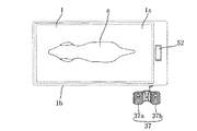
本発明において、図において示される符号1は、可動台10上に折り畳み昇降機構20を介して架設したペット台である。
In the present invention, a
図2乃至図5に示すように、可動台10は、ステンレス製の四角形のフレーム10aにて形成されると共に、その下面には、移動用のストッパ付きのキャスタ(キャスターアジャスタ)11が取り付けられ、ペットaの診察台または手術台として使用する場合に、このキャスタ11のストッパによってペット台が不用意に動かないようにしてある。
As shown in FIGS. 2 to 5, the
ペット台1は、ステンレス製の四角形の平板部1aと、その四周下端に突設されたフレーム1bとより成る。そして、フレーム1bの後方側(図3の左側)内部には、一対のガイド部3、3が対向配置されている。このガイド部3は、一対のコ字状枠3a、3aにて形成され、開口部が互いに対向するようフレーム1bの内側にそれぞれ固定されている。
The
可動台10のフレーム10aの後方側(図3の左側)には一対のガイド部12、12が対向配置されている。このガイド部12も、一対のコ字状枠12a、12aにて形成され、ペット台1のコ字状枠3a、3aと対応する直下に、開口部が互いに対向するようフレーム10aの内側にそれぞれ固定されている。
A pair of
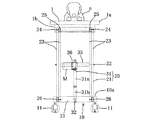
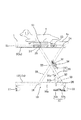
折り畳み昇降機構20は、ステンレス製のパンタグラフ機構21と1個のダンパ型伸縮機構31とを主要部材として構成されている。
The folding elevating
パンタグラフ機構21は、略中央交叉部において軸22にて回動自在に軸支されている一対のX脚23、23を備えている。そして、両X脚23、23の上端の一方は、ペット台1のフレーム1b両側の一側近傍内面にピン24にてそれぞれ回動自在に軸支されている。
The
両X脚23、23の上端の他方は、ガイドローラ25、25が回動自在に枢支されており、ペット台1のフレーム1b両側の他端側(後部側)内面に対向配置されたガイド部3、3として設けられたコ字状枠3a、3aにそれぞれ回転移動自在に係合されている。
両X脚23、23の下端の一方は、可動台10の前記ペット台1における軸支部と対応する直下にピン26にてそれぞれ回動自在に軸支されている。そして、下端の他方にも、ガイドローラ25、25が回動自在に枢着されており、ペット台1のガイド部3、3と対応する直下のガイド部12、12として設けられたコ字状枠12a、12aにそれぞれ回転移動自在に係合されている。
One of the lower ends of the
一方、ダンパ型伸縮機構31は、パンタグラフ機構21におけるX脚23、23下端の軸支側(図3の右側)に架け渡された連結角棒33の中央に一対の支持アーム32が設けられ、この一対の支持アーム32先端に、ピストンロッド31b下端が回動自在に軸支されている。
On the other hand, the damper type expansion /
反対側のX脚23、23の略中央側には、略逆L字型の支持板35が水平状態に架け渡されており、該支持板35の中央にシリンダ31a上端が固定されている。
A substantially inverted L-
図1乃至図5に示すように、シリンダ31a側には、ピストンロッド31bを伸縮動作するためのモータM付きの電動アクチュエータ36を備えている。そして、可動台10の近傍には、ペダル踏圧操作用のフットスイッチ37が設置される。このフットスイッチ37は、X脚23、23を折り畳み方向へ作動させるためのスイッチ37aと、X脚23、23を伸長させるためのスイッチ37bとが左右に設けられている。
As shown in FIGS. 1 to 5, an
このフットスイッチ37の足踏み操作により、電動アクチュエータ36のモータMが0N作動して、シリンダ31aに対してピストンロッド31bを支持アーム32先端で回転させつつ伸縮動作させ、これによってX脚23、23が伸長したり折り畳まれたりする。尚、フットスイッチ37の替わりに、ペット台1に備えた操作ボタン、有線あるいは無線方式の操作ボタン等(不図示)により、電動アクチュエータ36のモータMをON・OFF可能にしても良い。
By the stepping operation of the
さらに、可動台10の上部等にバッテリー(不図示)を脱着自在に搭載できるようにしても良い。このバッテリーを電源とすることにより、コンセント等が無い所でもモータMを作動させることもできる。
尚、上記した電動アクチュエータ36の構成は、本発明を何等限定するものではなく、他の種々の電動アクチュエータ36の構成を採用しても良いことは勿論である。
Further, a battery (not shown) may be detachably mounted on the movable table 10 or the like. By using this battery as a power source, the motor M can be operated even in a place without an outlet or the like.
Note that the configuration of the
また、図1、図3、図4に示すように、ペット台1の下面側には、体重計センサ51が設けられ、さらに、ペット台1の上面所定部位には、例えば、液晶表示パネル等による体重表示部52を設けてある。この体重計センサ51はスイッチ53によってON・OFF作動させる。尚、ペットaをペット台1に載せるだけで、自動的にスイッチ53が入るようにすることもできる。
As shown in FIGS. 1, 3, and 4, a
具体的には、図6(a)に示すように、ペット台1は、体重計センサ51の電子式計量秤(ロードセル)54に支持されている。この電子式計量秤54は、ペットaを載せたペット台1全体を計量した後に、この計量値からペットa以外のペット台1等の重量を減算することによってペットaの重量を計測するようになっている。
Specifically, as shown in FIG. 6A, the pet table 1 is supported by an electronic weighing scale (load cell) 54 of the
すなわち、電子式計量秤54は制御機構55を介して電動アクチュエータ36のモータMに接続されている。したがって、モータMは、電子式計量秤54からの信号を受けた制御機構55によって、この回転が制御される。制御機構55は計量コントローラ56およびモータMの回転スピードコントローラ57を備えている。
That is, the electronic weighing
図6(b)のフローチャートで示したように、ペット台1にペットaが載せられると同時に、計量コントローラ56は電子式計量秤54からの信号が入力され、そのコントロール信号を回転スピードコントローラ57に出力する。回転スピードコントローラ57はモータMに接続されており、計量コントローラ56からのコントロール信号に基づいてモータMの回転速度を制御する。これにより、ペット台1を昇降移動させる際には、ペット台1に載せられたペットaの体重に応じて電動アクチュエータ36のモータMの回転速度が制御される。
As shown in the flowchart of FIG. 6B, at the same time when the pet a is placed on the pet table 1, the weighing
すなわち、一定の動力Pを得る場合、モータトルクTと回転数n(回転速度・角速度)とは反比例する(T×n=定数×P)。これにより、所定の動力Pを得ている場合、回転数nを大きくすれば、モータトルクTが小さくて済む。したがって、負荷の軽減となる。一方、モータトルクTが一定の場合には、回転数nを大きくすることで大きな動力Pが得られる。この原理に従って、計量コントローラ56で、ペットaの重量が重いか軽いかの判断信号を、回転スピートコントローラ57に送り、この回転スピードコントローラ57でモータMの回転数nを制御するものとしている。
That is, when obtaining a constant power P, the motor torque T and the rotational speed n (rotational speed / angular speed) are inversely proportional (T × n = constant × P). Thereby, when the predetermined power P is obtained, the motor torque T can be reduced by increasing the rotational speed n. Therefore, the load is reduced. On the other hand, when the motor torque T is constant, a large power P can be obtained by increasing the rotational speed n. In accordance with this principle, the weighing
これによって、体重の重い大きなペットaは安全性を考慮して低速でペット台1が上下動する一方で、体重の軽い小さなペットaは、比較的高速でペット台1が上下動するようになっている。
ちなみに、電動アクチュエータ36のモータMの回転制御を電子式計量秤(ロードセル)54とを切り離して所定の定速度にて行なえるようにすることも可能である。
Accordingly, the pet table 1 moves up and down at a low speed for a large pet a with a heavy weight, while the pet table 1 moves up and down at a relatively high speed for a small pet a with a light weight. ing.
Incidentally, it is also possible to perform rotation control of the motor M of the
次に、以上のように構成されたペット用電動ストレッチャーの使用、動作の一例について説明する。 Next, an example of use and operation of the electric stretcher for pets configured as described above will be described.
先ず、診察あるいは手術を必要とするペットaをペット台1上面に載せ、所定の場所に搬送する。ペットaを診察または手術する際には、キャスタ11のストッパによってペット台1が不用意に動かないようにする。
First, a pet a requiring medical examination or surgery is placed on the upper surface of the pet table 1 and conveyed to a predetermined place. When examining or operating the pet a, the stopper of the
また、ペット台1下面に配した体重計センサ51により自動的にペットaの体重が計測され、体重表示部52に表示される。
Further, the weight of the pet a is automatically measured by the
この体重計測においては、図6(b)のフローチャートで示したように、電子式計量秤54が、ペットaを載せたペット台1全体を計量した後に、この計量値からペットa以外のペット台1等の重量を減算する(ステップS1)。これによってペットaの重量が計測される。
In this weight measurement, as shown in the flowchart of FIG. 6 (b), after the electronic weighing
そして、計量コントローラ56は電子式計量秤54からの信号が入力される(ステップS2)。また、そのコントロール信号を回転スピードコントローラ57に出力する(ステップS3)。
The weighing
次いで、モータMに接続された回転スピードコントローラ57は、計量コントローラ56からのコントロール信号に基づいてモータMの回転速度を制御する(ステップS4)。
Next, the
これにより、ペット台1を昇降移動させる際には、ペット台1に載せられたペットaの体重に応じて電動アクチュエータ36のモータMの回転速度が制御されるのである。すなわち、体重の重い大きなペットaはモータMの回転速度を遅くしてペット台1の動作をゆっくりさせる一方、体重の軽い小さなペットaはモータMの回転速度を早くしてペット台1の動作を早くすることができる。
Thus, when the pet table 1 is moved up and down, the rotation speed of the motor M of the
次いで、フットスイッチ37における、X脚23、23を折り畳み方向へ作動させるためのスイッチ37aを足で踏むと、電動アクチュエータ36のモータMが正回転して、シリンダ31aに対してピストンロッド31bを収縮動作させ、これによってX脚23、23が折り畳まれ、ペット台1が押し下げられる(図4、図5参照)。このとき、足による踏圧を解除すれば、電動アクチュエータ36のモータMへの通電が遮断されて、ペット台1が所定の低さ位置で停止される。
Next, when the
一方、フットスイッチ37における、X脚23、23を伸長方向へ作動させるためのスイッチ37bを足で踏むと、電動アクチュエータ36のモータMが逆回転して、シリンダ31aに対してピストンロッド31bを伸長動作させ、これによってX脚23、23が伸長され、ペット台1が押し上げられる(図2、図3参照)。このとき、足による踏圧を解除すれば、電動アクチュエータ36のモータMへの通電が遮断されて、ペット台1が所定の高さ位置で停止される。
On the other hand, when the
而して、従来の折り畳み昇降機構では不可能であったペット台の高低差の設定が可能となり、且つ、できるだけ大きく設定することができ、しかも、この高低差の間でのペット台の高さ位置の微調整が適確且つスムーズに行える。 Thus, it is possible to set the height difference of the pet table, which is impossible with the conventional folding lifting mechanism, and it can be set as large as possible, and the height of the pet table between the height differences is also possible. Fine adjustment of the position can be performed accurately and smoothly.
M モータ
a ペット
1 ペット台
1a 平板部
1b フレーム
3 ガイド部
3a コ字状枠
10 可動台
10a フレーム
11 キャスタ
12 ガイド部
12a コ字状枠
20 折り畳み昇降機構
21 パンタグラフ機構
22 軸
23 X脚
24 ピン
25 ガイドローラ
26 ピン
31 ダンパ型伸縮機構
31a シリンダ
31b ピストンロッド
32 支持アーム
33 連結角棒
35 支持板
36 電動アクチュエータ
37(37a、37b) フットスイッチ
51 体重計センサ
52 体重表示部
53 スイッチ
54 電子式計量秤(ロードセル)
55 制御機構
56 計量コントローラ
57 回転スピードコントローラ
M motor a
55
Claims (3)
前記可動台は、下面に移動用のキャスタが取り付けられており、
前記折り畳み昇降機構は、パンタグラフ機構とダンパ型伸縮機構とを主要部材としており、パンタグラフ機構は、略中央交叉部において回動自在に軸支される一対のX脚を備え、両X脚の上端は、ペット台側に回動自在に軸支され、両X脚の下端は、可動台側に回動自在に軸支され、
一方、ダンパ型伸縮機構は、パンタグラフ機構における一方のX脚に回動自在に軸支されたピストンロッドと、該ピストンロッドが挿入され、他方のX脚に配されたシリンダとを備え、
前記シリンダ側には、当該ピストンロッドを伸縮動作するモータ付きの電動アクチュエータを備えて成ることを特徴とするペット用電動ストレッチャー兼診察台。 An electric stretcher and examination table for pets, in which a pet table is folded on a movable table and installed via an elevating mechanism,
The movable table has a moving caster attached to the lower surface,
The folding elevating mechanism has a pantograph mechanism and a damper-type expansion / contraction mechanism as main members, and the pantograph mechanism includes a pair of X legs pivotally supported at a substantially central intersection, and the upper ends of both X legs are The lower end of both X legs is pivotally supported on the movable table side, and is pivotally supported on the pet table side.
On the other hand, the damper-type expansion / contraction mechanism includes a piston rod pivotally supported on one X leg in the pantograph mechanism, and a cylinder in which the piston rod is inserted and disposed on the other X leg,
An electric stretcher and examination table for pets, comprising an electric actuator with a motor for extending and contracting the piston rod on the cylinder side.
Priority Applications (1)
| Application Number | Priority Date | Filing Date | Title |
|---|---|---|---|
| JP2009029383A JP2010184003A (en) | 2009-02-12 | 2009-02-12 | Examination table also used as electric stretcher for pet |
Applications Claiming Priority (1)
| Application Number | Priority Date | Filing Date | Title |
|---|---|---|---|
| JP2009029383A JP2010184003A (en) | 2009-02-12 | 2009-02-12 | Examination table also used as electric stretcher for pet |
Publications (2)
| Publication Number | Publication Date |
|---|---|
| JP2010184003A true JP2010184003A (en) | 2010-08-26 |
| JP2010184003A5 JP2010184003A5 (en) | 2012-03-15 |
Family
ID=42765018
Family Applications (1)
| Application Number | Title | Priority Date | Filing Date |
|---|---|---|---|
| JP2009029383A Pending JP2010184003A (en) | 2009-02-12 | 2009-02-12 | Examination table also used as electric stretcher for pet |
Country Status (1)
| Country | Link |
|---|---|
| JP (1) | JP2010184003A (en) |
Citations (8)
| Publication number | Priority date | Publication date | Assignee | Title |
|---|---|---|---|---|
| JPH06254086A (en) * | 1993-03-05 | 1994-09-13 | Toshiba Corp | Examinee placing bed |
| JPH0966067A (en) * | 1995-09-01 | 1997-03-11 | Osada Res Inst Ltd | Veterinary examination table system |
| JP3067867U (en) * | 1999-10-01 | 2000-04-11 | 株式会社プラッツ | Bed lifting device |
| JP2001128966A (en) * | 1999-11-05 | 2001-05-15 | Obayashi Seisakusho:Kk | Radiographing apparatus |
| JP2002320651A (en) * | 2001-04-25 | 2002-11-05 | Paramount Bed Co Ltd | Lifting legs for furniture |
| JP2005052185A (en) * | 2003-08-01 | 2005-03-03 | Tokyo Menitsukusu:Kk | Stretcher for pet |
| JP2005348983A (en) * | 2004-06-11 | 2005-12-22 | Seahonence Inc | Lifting device of electric-adjustable bed |
| JP3929167B2 (en) * | 1998-04-08 | 2007-06-13 | オージー技研株式会社 | Transport vehicle with support device |
-
2009
- 2009-02-12 JP JP2009029383A patent/JP2010184003A/en active Pending
Patent Citations (8)
| Publication number | Priority date | Publication date | Assignee | Title |
|---|---|---|---|---|
| JPH06254086A (en) * | 1993-03-05 | 1994-09-13 | Toshiba Corp | Examinee placing bed |
| JPH0966067A (en) * | 1995-09-01 | 1997-03-11 | Osada Res Inst Ltd | Veterinary examination table system |
| JP3929167B2 (en) * | 1998-04-08 | 2007-06-13 | オージー技研株式会社 | Transport vehicle with support device |
| JP3067867U (en) * | 1999-10-01 | 2000-04-11 | 株式会社プラッツ | Bed lifting device |
| JP2001128966A (en) * | 1999-11-05 | 2001-05-15 | Obayashi Seisakusho:Kk | Radiographing apparatus |
| JP2002320651A (en) * | 2001-04-25 | 2002-11-05 | Paramount Bed Co Ltd | Lifting legs for furniture |
| JP2005052185A (en) * | 2003-08-01 | 2005-03-03 | Tokyo Menitsukusu:Kk | Stretcher for pet |
| JP2005348983A (en) * | 2004-06-11 | 2005-12-22 | Seahonence Inc | Lifting device of electric-adjustable bed |
Similar Documents
| Publication | Publication Date | Title |
|---|---|---|
| US5205004A (en) | Vertically adjustable and tiltable bed frame | |
| US11896533B2 (en) | System, apparatus and method for supporting and/or positioning a patient before, during, or after a medical procedure | |
| JP2009056247A5 (en) | ||
| JP2008125981A (en) | Universal photography system | |
| JP2013523397A5 (en) | ||
| JP2012050622A5 (en) | Ophthalmic equipment | |
| US7736054B2 (en) | X-ray detecting device and X-ray imaging apparatus | |
| JP2013056041A (en) | Standing assistance system | |
| JP2010184003A (en) | Examination table also used as electric stretcher for pet | |
| AU2017402430A1 (en) | Assistance device | |
| JP2010184003A5 (en) | ||
| JP2005052185A (en) | Stretcher for pet | |
| JP2014061150A (en) | Supine table bottom control method and device therefor | |
| JP2009022512A (en) | Dental treatment chair | |
| JP5304440B2 (en) | Reclining bed drive | |
| TW201228652A (en) | Bed device and feet parts descending mechanism | |
| TWI549669B (en) | Bed rest | |
| JP6079873B2 (en) | Round-trip X-ray equipment | |
| KR20110137150A (en) | Safety device for lower limb rehabilitation machine | |
| JP2007330440A (en) | X-ray radiographing apparatus | |
| JP3911186B2 (en) | Balance measuring instrument | |
| JP7200529B2 (en) | Optometry table and optometry system | |
| JP2010240010A (en) | Proximity operation type fluoroscopic imaging apparatus | |
| ITMI980490A1 (en) | TILTING PATIENT HOLDER TABLE IN PARTICULAR FOR X-RAY EXAMINATIONS | |
| JP2022173654A (en) | Motor-driven optical base and inspection system |
Legal Events
| Date | Code | Title | Description |
|---|---|---|---|
| RD02 | Notification of acceptance of power of attorney |
Free format text: JAPANESE INTERMEDIATE CODE: A7422 Effective date: 20101005 |
|
| RD05 | Notification of revocation of power of attorney |
Free format text: JAPANESE INTERMEDIATE CODE: A7425 Effective date: 20101110 |
|
| A521 | Written amendment |
Free format text: JAPANESE INTERMEDIATE CODE: A523 Effective date: 20101129 |
|
| A521 | Written amendment |
Free format text: JAPANESE INTERMEDIATE CODE: A523 Effective date: 20120131 |
|
| A621 | Written request for application examination |
Free format text: JAPANESE INTERMEDIATE CODE: A621 Effective date: 20120131 |
|
| A131 | Notification of reasons for refusal |
Free format text: JAPANESE INTERMEDIATE CODE: A131 Effective date: 20130304 |
|
| A02 | Decision of refusal |
Free format text: JAPANESE INTERMEDIATE CODE: A02 Effective date: 20130625 |