JP2010181663A - Image forming apparatus - Google Patents
Image forming apparatus Download PDFInfo
- Publication number
- JP2010181663A JP2010181663A JP2009025559A JP2009025559A JP2010181663A JP 2010181663 A JP2010181663 A JP 2010181663A JP 2009025559 A JP2009025559 A JP 2009025559A JP 2009025559 A JP2009025559 A JP 2009025559A JP 2010181663 A JP2010181663 A JP 2010181663A
- Authority
- JP
- Japan
- Prior art keywords
- image
- image forming
- toner
- color material
- transparent
- Prior art date
- Legal status (The legal status is an assumption and is not a legal conclusion. Google has not performed a legal analysis and makes no representation as to the accuracy of the status listed.)
- Granted
Links
- 239000000463 material Substances 0.000 claims abstract description 44
- 230000015572 biosynthetic process Effects 0.000 claims description 45
- 230000006866 deterioration Effects 0.000 abstract description 2
- 238000000034 method Methods 0.000 description 10
- 238000010586 diagram Methods 0.000 description 9
- 238000004140 cleaning Methods 0.000 description 3
- 230000007547 defect Effects 0.000 description 2
- 238000011144 upstream manufacturing Methods 0.000 description 2
- 239000000428 dust Substances 0.000 description 1
- 239000000203 mixture Substances 0.000 description 1
Images
Classifications
-
- G—PHYSICS
- G03—PHOTOGRAPHY; CINEMATOGRAPHY; ANALOGOUS TECHNIQUES USING WAVES OTHER THAN OPTICAL WAVES; ELECTROGRAPHY; HOLOGRAPHY
- G03G—ELECTROGRAPHY; ELECTROPHOTOGRAPHY; MAGNETOGRAPHY
- G03G15/00—Apparatus for electrographic processes using a charge pattern
- G03G15/50—Machine control of apparatus for electrographic processes using a charge pattern, e.g. regulating differents parts of the machine, multimode copiers, microprocessor control
-
- G—PHYSICS
- G03—PHOTOGRAPHY; CINEMATOGRAPHY; ANALOGOUS TECHNIQUES USING WAVES OTHER THAN OPTICAL WAVES; ELECTROGRAPHY; HOLOGRAPHY
- G03G—ELECTROGRAPHY; ELECTROPHOTOGRAPHY; MAGNETOGRAPHY
- G03G15/00—Apparatus for electrographic processes using a charge pattern
- G03G15/01—Apparatus for electrographic processes using a charge pattern for producing multicoloured copies
- G03G15/0142—Structure of complete machines
- G03G15/0178—Structure of complete machines using more than one reusable electrographic recording member, e.g. one for every monocolour image
- G03G15/0194—Structure of complete machines using more than one reusable electrographic recording member, e.g. one for every monocolour image primary transfer to the final recording medium
-
- G—PHYSICS
- G03—PHOTOGRAPHY; CINEMATOGRAPHY; ANALOGOUS TECHNIQUES USING WAVES OTHER THAN OPTICAL WAVES; ELECTROGRAPHY; HOLOGRAPHY
- G03G—ELECTROGRAPHY; ELECTROPHOTOGRAPHY; MAGNETOGRAPHY
- G03G15/00—Apparatus for electrographic processes using a charge pattern
- G03G15/65—Apparatus which relate to the handling of copy material
- G03G15/6582—Special processing for irreversibly adding or changing the sheet copy material characteristics or its appearance, e.g. stamping, annotation printing, punching
- G03G15/6585—Special processing for irreversibly adding or changing the sheet copy material characteristics or its appearance, e.g. stamping, annotation printing, punching by using non-standard toners, e.g. transparent toner, gloss adding devices
-
- G—PHYSICS
- G03—PHOTOGRAPHY; CINEMATOGRAPHY; ANALOGOUS TECHNIQUES USING WAVES OTHER THAN OPTICAL WAVES; ELECTROGRAPHY; HOLOGRAPHY
- G03G—ELECTROGRAPHY; ELECTROPHOTOGRAPHY; MAGNETOGRAPHY
- G03G15/00—Apparatus for electrographic processes using a charge pattern
- G03G15/01—Apparatus for electrographic processes using a charge pattern for producing multicoloured copies
- G03G15/0142—Structure of complete machines
- G03G15/0147—Structure of complete machines using a single reusable electrographic recording member
- G03G15/0152—Structure of complete machines using a single reusable electrographic recording member onto which the monocolour toner images are superposed before common transfer from the recording member
- G03G15/0173—Structure of complete machines using a single reusable electrographic recording member onto which the monocolour toner images are superposed before common transfer from the recording member plural rotations of recording member to produce multicoloured copy, e.g. rotating set of developing units
-
- G—PHYSICS
- G03—PHOTOGRAPHY; CINEMATOGRAPHY; ANALOGOUS TECHNIQUES USING WAVES OTHER THAN OPTICAL WAVES; ELECTROGRAPHY; HOLOGRAPHY
- G03G—ELECTROGRAPHY; ELECTROPHOTOGRAPHY; MAGNETOGRAPHY
- G03G2215/00—Apparatus for electrophotographic processes
- G03G2215/00362—Apparatus for electrophotographic processes relating to the copy medium handling
- G03G2215/00789—Adding properties or qualities to the copy medium
- G03G2215/00805—Gloss adding or lowering device
- G03G2215/0081—Gloss level being selectable
-
- G—PHYSICS
- G03—PHOTOGRAPHY; CINEMATOGRAPHY; ANALOGOUS TECHNIQUES USING WAVES OTHER THAN OPTICAL WAVES; ELECTROGRAPHY; HOLOGRAPHY
- G03G—ELECTROGRAPHY; ELECTROPHOTOGRAPHY; MAGNETOGRAPHY
- G03G2215/00—Apparatus for electrophotographic processes
- G03G2215/01—Apparatus for electrophotographic processes for producing multicoloured copies
- G03G2215/0103—Plural electrographic recording members
- G03G2215/0119—Linear arrangement adjacent plural transfer points
- G03G2215/0122—Linear arrangement adjacent plural transfer points primary transfer to an intermediate transfer belt
- G03G2215/0125—Linear arrangement adjacent plural transfer points primary transfer to an intermediate transfer belt the linear arrangement being horizontal or slanted
- G03G2215/0129—Linear arrangement adjacent plural transfer points primary transfer to an intermediate transfer belt the linear arrangement being horizontal or slanted horizontal medium transport path at the secondary transfer
Landscapes
- Physics & Mathematics (AREA)
- General Physics & Mathematics (AREA)
- Engineering & Computer Science (AREA)
- Microelectronics & Electronic Packaging (AREA)
- Color Electrophotography (AREA)
- Control Or Security For Electrophotography (AREA)
Abstract
Description
本発明は、画像形成装置に関する。 The present invention relates to an image forming apparatus.
電子写真方式の画像形成装置は、感光体ドラムや中間体ベルト等といった像保持体上に有色色材であるトナーを用いて像形成を行い、その形成したトナー像を印刷用紙等の記録媒体へ転写して、当該記録媒体上への画像形成を行う。
像保持体上の像形成領域内には、有色色材によるトナー像に相当する画像部分と、記録媒体の下地(地色)がそのまま現われる非画像部分とが混在する。そして、非画像部分には、有色色材であるトナーが、本来は載らないはずであるのに僅かながら付着してしまう、いわゆる「トナーカブリ」が発生し得ることが知られている。
このトナーカブリについては、画像部分・非画像部分の違いに応じて、カブリ防止電位(Vclean)のレベルを変更することで、その発生を抑制することが提案されている(例えば、特許文献1参照。)。
An electrophotographic image forming apparatus forms an image using a toner that is a color material on an image carrier such as a photosensitive drum or an intermediate belt, and the formed toner image is applied to a recording medium such as a printing paper. Transfer is performed to form an image on the recording medium.
In the image forming area on the image carrier, there are a mixture of an image portion corresponding to a toner image made of a color material and a non-image portion where the background (ground color) of the recording medium appears as it is. In addition, it is known that a toner that is a colored color material may adhere to a non-image portion, although it should not be mounted, so-called “toner fogging”.
It has been proposed to suppress the occurrence of toner fog by changing the level of the anti-fogging potential (Vclean) according to the difference between the image portion and the non-image portion (see, for example, Patent Document 1). .)
しかしながら、カブリ防止電位の制御処理は複雑であり、特に画像部分・非画像部分の構成が微小な場合には完全な制御は略不可能であると考えられる。さらに、画像欠損等の2次障害も多くなるおそれがある。 However, the anti-fogging potential control process is complicated, and it is considered that complete control is almost impossible particularly when the configuration of the image portion and the non-image portion is minute. Furthermore, there is a risk that secondary defects such as image defects may increase.
つまり、画像形成装置に対しては、制御処理の複雑化等を要することなく、トナーカブリ発生に起因する記録媒体上の画像劣化を、確実に回避できるようにすることが求められている。 That is, the image forming apparatus is required to reliably avoid image deterioration on the recording medium due to the occurrence of toner fog without requiring complicated control processing.
請求項1に係る発明は、以下のとおりである。すなわち、透明色材および有色色材を用いて像保持体上への像形成を行う像形成手段と、前記像保持体上の像形成領域における画像部分と非画像部分で前記透明色材と前記有色色材の形成順を相違させる形成順制御手段と、前記像保持体上に形成された像を記録媒体上に転写する転写手段とを備えることを特徴とする画像形成装置である。
請求項2に係る発明は、以下のとおりである。すなわち、前記画像部分は、前記透明色材の後に前記有色色材を用いる形成順とし、前記非画像部分は、最後に前記透明色材を用いる形成順とすることを特徴とする請求項1記載の画像形成装置である。
請求項3に係る発明は、以下のとおりである。すなわち、前記像形成手段は、前記画像部分のために前記透明色材による像形成を行う第1透明像形成部と、前記非画像部分のために前記透明色材による像形成を行う第2透明像形成部とを備え、前記像保持体の一周の間に前記第1透明像形成部と前記第2透明像形成部とのそれぞれが当該像保持体上への像形成を行うように構成されていることを特徴とする請求項1または2記載の画像形成装置である。
請求項4に係る発明は、以下のとおりである。すなわち、前記像形成手段は、前記透明色材による像形成を行う一つの透明像形成部を備え、前記像保持体の複数周の間に前記一つの透明像形成部が前記画像部分のための当該像保持体上への像形成と前記非画像部分のための当該像保持体上への像形成とのそれぞれを行うように構成されていることを特徴とする請求項1または2記載の画像形成装置である。
The invention according to claim 1 is as follows. That is, an image forming means for forming an image on an image carrier using a transparent color material and a color material, and the transparent color material and the image portion in the image forming area on the image carrier and the non-image portion. An image forming apparatus comprising: a forming order control unit that changes a forming order of the color materials; and a transfer unit that transfers an image formed on the image carrier onto a recording medium.
The invention according to claim 2 is as follows. That is, the image portion is formed in the order of using the colored color material after the transparent color material, and the non-image portion is finally formed in the order of using the transparent color material. This is an image forming apparatus.
The invention according to claim 3 is as follows. That is, the image forming means includes a first transparent image forming unit that forms an image with the transparent color material for the image portion, and a second transparent image that forms an image with the transparent color material for the non-image portion. An image forming unit, and each of the first transparent image forming unit and the second transparent image forming unit is configured to form an image on the image holding member during one rotation of the image holding member. The image forming apparatus according to claim 1, wherein the image forming apparatus is an image forming apparatus.
The invention according to claim 4 is as follows. That is, the image forming unit includes a single transparent image forming unit that forms an image with the transparent color material, and the single transparent image forming unit is used for the image portion between a plurality of circumferences of the image holding member. 3. The image according to claim 1, wherein the image formation on the image carrier and the image formation on the image carrier for the non-image portion are each performed. Forming device.
請求項1に係る発明によれば、例えば「トナーカブリ」が発生しても、透明色材と有色色材の形成順制御を通じて、非画像部分に付着した有色色材の記録媒体上への転写を、本構成を有していない場合と比較して抑制できる。
請求項2に係る発明によれば、本構成を有していない場合と比較して、画像部分と非画像部分とのいずれにも透明色材を用いた像形成を行うので、画像形成面内における光沢性均一化が損なわれず、かつ画像部分については有色色材の記録媒体上への転写性向上が実現されるのに対して、非画像部分では当該非画像部分に付着した有色色材の記録媒体上への転写を抑制できる。
請求項3に係る発明によれば、本構成を有していない場合と比較して当該像形成の迅速化が図れる。
請求項4に係る発明によれば、画像部分と非画像部分とについて透明色材と有色色材の形成順制御を行う場合であっても、一つの透明像形成部を用いて像保持体上への像形成を行えるので、当該像形成のための構成の複雑化を招くことがなく、既存構成を流用できる等の汎用性が確保されることになる。
According to the first aspect of the present invention, for example, even when “toner fogging” occurs, the color material attached to the non-image portion is transferred onto the recording medium through the formation order control of the transparent color material and the color material. Can be suppressed as compared with the case of not having this configuration.
According to the second aspect of the present invention, since image formation using a transparent color material is performed on both the image portion and the non-image portion as compared with the case where the present configuration is not provided, the image forming surface In the non-image portion, the color material adhering to the non-image portion is improved. Transfer onto the recording medium can be suppressed.
According to the third aspect of the present invention, the image formation can be speeded up as compared with the case where the present configuration is not provided.
According to the invention of claim 4, even when the formation order control of the transparent color material and the colored color material is performed for the image portion and the non-image portion, the single image forming portion is used on the image carrier. Therefore, it is possible to ensure versatility such that the existing configuration can be used without complicating the configuration for forming the image.
以下、図面に基づき本発明に係る画像形成装置について説明する。
以下に説明する画像形成装置は、いずれの実施の形態においても、電子写真方式により記録媒体上への画像出力を行うものであり、具体的には複写機やプリンタ装置等として用いられるものである。画像が出力される記録媒体としては、普通紙または再生紙といった印刷用紙やOHPシート等が挙げられるが、どのような種類のものかは特に限定されることなく、ここでは単に「用紙」として以下の説明を行う。
The image forming apparatus according to the present invention will be described below with reference to the drawings.
An image forming apparatus described below outputs an image on a recording medium by an electrophotographic method in any of the embodiments, and is specifically used as a copying machine, a printer apparatus, or the like. . Examples of the recording medium on which an image is output include printing paper such as plain paper or recycled paper, and an OHP sheet. However, there is no particular limitation on the type of the recording medium. Will be explained.
<第1の実施の形態>
先ず、本発明の第1の実施の形態における画像形成装置について説明する。
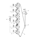
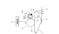
図1は、本発明の第1の実施の形態における画像形成装置の要部構成例を示す説明図である。
図例の画像形成装置は、複数(具体的には、6つ。)の像形成部11〜16と、像保持体としての中間体ベルト21と、二次転写装置22と、定着器23と、これらの動作を制御する制御装置24と、を備えて構成されている。すなわち、図例の画像形成装置は、6つの像形成部11〜16が一列に並設された、いわゆる「タンデム方式」のものである。
<First Embodiment>
First, the image forming apparatus according to the first embodiment of the present invention will be described.
FIG. 1 is an explanatory diagram illustrating an exemplary configuration of a main part of the image forming apparatus according to the first embodiment of the present invention.
The illustrated image forming apparatus includes a plurality of (specifically, six)
各像形成部11〜16は、いずれも、帯電→露光→現像→転写の各プロセスを経て画像形成を行う。そのために、各像形成部11〜16は、回転駆動される像保持体としての感光体ドラムと、その感光体ドラムの表面を一様に帯電する帯電器と、当該感光体ドラムの表面に静電潜像を形成する露光装置と、感光体ドラム上の静電潜像を現像してトナー像を形成する現像器と、感光体ドラム上のトナー像を中間体ベルト21上へ転写する一次転写装置と、感光体ドラム上の残留トナー等の異物を除去するクリーニング装置と、を有している。なお、これらの各構成要素の詳細については、公知であるため、ここではその説明を省略する。
Each of the
ただし、各像形成部11〜16は、それぞれが異なる色材(トナー)を用いて像形成を行うようになっている。すなわち、一列に並設された各像形成部11〜16のうち、両端のものを除く4つの像形成部12〜15は、それぞれがイエロー(Y)、マゼンタ(M)、シアン(C)、ブラック(K)の各色に対応した有色色材(カラートナー)を用いて、像形成を行う。一方、両端に位置する2つの像形成部11,16は、いずれも透明色材であるクリアートナーを用いて、像形成を行う。
つまり、各像形成部11〜16は、透明色材であるクリアートナーおよび有色色材であるカラートナーを用いて像形成を行う像形成手段として機能するのである。
このうち、クリアートナーを用いる像形成部11,16は、詳細を後述するように、中間体ベルト21の搬送方向上流側に位置する像形成部11が第1透明像形成部として機能し、搬送方向下流側に位置する像形成部16が第2透明像形成部として機能するようになっている。
However, the
That is, each of the
Among these, the
中間体ベルト21は、無端ベルト状に形成され、各像形成部11〜16における一次転写装置を通過するように同一の速度で循環駆動されるものであり、各像形成部11〜16で形成されたトナー像が転写されて重ねられるものである。なお、この中間体ベルト21に対しては、当該中間体ベルト21上の残留トナーや紙粉等の異物を除去するクリーニング装置が設けられていてもよい。
二次転写装置22は、像保持体である中間体ベルト21上のトナー像を、記録媒体である用紙上へ転写するものである。つまり、二次転写装置22は、中間体ベルト21から用紙へのトナー像転写を行う転写手段として機能するようになっている。
定着器23は、電子写真方式における定着プロセスを実行するもの、すなわち二次転写装置22にてトナー像が転写された後の用紙に対して、熱および圧力による定着処理を行って、その用紙上の転写像の定着を行うものである。
なお、中間体ベルト21、二次転写装置22および定着器23については、公知であるため、ここではその形成材料や動作原理等に関する詳細な説明を省略する。
The
The
The fixing
Since the
制御装置24は、マイクロコンピュータとして機能するCPU(Central Processing Unit)を有して構成されており、上述した各部11〜16,21〜23における動作を制御して、用紙上への画像出力等の処理を行うようになっている。
制御装置24が行う動作制御としては、以下に述べるようなものが挙げられる。
制御装置24では、各像形成部11〜16での像形成の基になる画像情報を参照しつつ、画像部分と非画像部分との別を認識する。ここで、「画像部分」とは、像保持体上の像形成領域内において、カラートナーによってトナー像が形成される部分のこと、すなわち当該トナー像そのものに相当する部分のことをいう。一方、「非画像部分」とは、像保持体上の像形成領域内において、カラートナーによるトナー像が形成されない部分のこと、すなわち用紙の下地(地色)がそのまま現われる部分のことをいう。このような画像部分と非画像部分との別は、例えば各画素毎の画像情報の値が「0」であるか「1」であるかによって認識することが考えられる。ただし、これに限定されることはなく、他の手法によって認識しても構わない。
そして、制御装置24では、画像部分と非画像部分との別を認識すると、その認識結果に基づき、当該画像部分と当該非画像部分とでクリアートナーとカラートナーの形成順を相違させるように、各像形成部11〜16に対して動作指示を与える。つまり、制御装置24は、各像形成部11〜16による像形成の順を制御する形成順制御手段として機能するようになっている。
The
The operation control performed by the
The
Then, when the
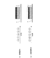
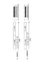
図2は、本発明の第1の実施の形態における像形成順に関する動作制御の具体例を示す説明図である。 FIG. 2 is an explanatory diagram showing a specific example of the operation control related to the image forming order in the first embodiment of the present invention.
図2(a)に示すように、画像部分についての像形成を行う場合に、制御装置24は、第1透明像形成部として機能してクリアートナーによるトナー像を形成する像形成部11、Y色のカラートナーによるトナー像を形成する像形成部12、M色のカラートナーによるトナー像を形成する像形成部13、C色のカラートナーによるトナー像を形成する像形成部14、および、K色のカラートナーによるトナー像を形成する像形成部15に対して、像形成を行うように動作指示を与える。ただし、第2透明像形成部として機能してクリアートナーによるトナー像を形成する像形成部16に対しては、像形成の指示を与えない。これにより、中間体ベルト21上には、当該中間体ベルト21上の像形成領域が各像形成部11〜16における一次転写装置を順に通過することにより、当該中間体ベルト21の側からクリアートナーによるトナー像、Y色のトナー像、M色のトナー像、C色のトナー像、および、K色のトナー像が順に積層されることになる。
As shown in FIG. 2A, when image formation is performed on an image portion, the
また、図2(b)に示すように、非画像部分についての像形成を行う場合に、制御装置24は、Y色のカラートナーによるトナー像を形成する像形成部12、M色のカラートナーによるトナー像を形成する像形成部13、C色のカラートナーによるトナー像を形成する像形成部14、および、K色のカラートナーによるトナー像を形成する像形成部15に対して、画像部分についての動作指示を与えた後に、第2透明像形成部として機能してクリアートナーによるトナー像を形成する像形成部16に対して、像形成を行うように動作指示を与える。ただし、第1透明像形成部として機能してクリアートナーによるトナー像を形成する像形成部11に対しては、像形成の指示を与えない。これにより、中間体ベルト21上には、当該中間体ベルト21上の像形成領域が各像形成部11〜16における一次転写装置を順に通過することにより、当該中間体ベルト21の側からY色のトナー像、M色のトナー像、C色のトナー像、K色のトナー像、および、クリアートナーによるトナー像が順に積層されることになる。
As shown in FIG. 2B, when image formation is performed on a non-image portion, the
つまり、制御装置24は、像形成順に関する動作制御にあたり、画像部分についてはクリアートナーの後にカラートナーを用いる形成順とする。一方、非画像部分については最後にクリアートナーを用いる形成順とする。このように、画像部分と非画像部分とで、クリアートナーとカラートナーの形成順を相違させるのである。
In other words, the
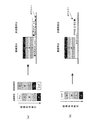
図3は、トナー像を用紙上に転写する場合の転写動作の具体例を示す説明図である。なお、図例では、比較のため、従来構成における転写動作の具体例についても、併せて示している。 FIG. 3 is an explanatory diagram showing a specific example of a transfer operation when a toner image is transferred onto a sheet. In the example of the drawing, a specific example of the transfer operation in the conventional configuration is also shown for comparison.
図3(b)に示すように、従来構成の場合には、画像部分と非画像部分との別に拘らず、ベルト側から順にクリアートナーによるトナー像、Y色のトナー像、M色のトナー像、C色のトナー像、K色のトナー像が順に形成される。そのため、クリアートナーがベルト上全面に存在することになり、非画像部分についても用紙上へのカラートナー像の転写性が向上する。つまり、非画像部分におけるカブリトナーまで効率よく転写されてしまうことになり、用紙上でトナーカブリの発生が顕在化してしまう。 As shown in FIG. 3B, in the case of the conventional configuration, regardless of the image portion and the non-image portion, the toner image by the clear toner, the Y color toner image, and the M color toner image are sequentially arranged from the belt side. C color toner image and K color toner image are formed in this order. Therefore, the clear toner is present on the entire surface of the belt, and the transferability of the color toner image onto the paper is improved even in the non-image portion. That is, the fog toner in the non-image portion is efficiently transferred, and the occurrence of toner fog on the paper becomes obvious.
これに対して、上述した構成の画像形成装置によれば、図3(a)に示すように、画像部分と非画像部分とで、クリアートナーとカラートナーの形成順が相違している。
画像部分では、中間体ベルト21上の最下層にクリアートナーの層が位置している。そのため、当該クリアートナーの層上に重なるカラートナーの層が、効率よく用紙上に転写されることになる。
その一方で、非画像部分については、最後にクリアートナーを用いる形成順とされているため、中間体ベルト21上の最上層にクリアートナーの層が位置することになる。したがって、例えば非画像部分にカブリトナーが存在しても、そのカブリトナーの下層側にはクリアートナーの層が存在していないので、画像部分の場合とは異なり、当該カブリトナーの用紙上への転写効率を向上させることはなく、その結果として当該カブリトナーの用紙上への転写が抑制されることになる。
On the other hand, according to the image forming apparatus configured as described above, as shown in FIG. 3A, the order of forming the clear toner and the color toner is different between the image portion and the non-image portion.
In the image portion, the clear toner layer is located in the lowermost layer on the
On the other hand, since the non-image portion is finally formed in the order of using the clear toner, the clear toner layer is positioned on the uppermost layer on the
しかも、画像部分には中間体ベルト21上の最下層に、また非画像部分には中間体ベルト21上の最上層に、クリアートナーの層が位置している。つまり、画像部分と非画像部分のいずれにも、クリアートナーの層が位置している。
したがって、用紙上へのカラートナー像の転写後においては、当該用紙上の画像部分と非画像部分のいずれにもクリアートナーの層が転写されることになり、当該用紙上における転写像の光沢感について画像部分と非画像部分で差が生じてしまうことがない。
In addition, the clear toner layer is located in the lowermost layer on the
Therefore, after the color toner image is transferred onto the paper, the clear toner layer is transferred to both the image portion and the non-image portion on the paper, and the glossiness of the transferred image on the paper is transferred. There is no difference between the image portion and the non-image portion.
さらに、第1の実施の形態における構成の画像形成装置では、画像部分のためにクリアートナーによる像形成を行う第1透明像形成部としての像形成部11と、非画像部分のためにクリアートナーによる像形成を行う第2透明像形成部としての像形成部16とを備えている。そのため、上述した像形成順に関する動作制御を制御装置24が行う場合であっても、中間体ベルト21が一周する間に、2つの像形成部11,16のそれぞれが当該中間体ベルト21上への像形成を行うことになる。つまり、クリアートナーを用いる像形成部11,16を2つ備えているので、画像部分と非画像部分とでクリアートナーとカラートナーの形成順を相違させる場合であっても、中間体ベルト21が一周する間、すなわちいわゆる1パスプロセスで、当該中間体ベルト21上へのトナー像形成が完了するのである。
Furthermore, in the image forming apparatus having the configuration according to the first embodiment, the
<第2の実施の形態>
次に、本発明の第2の実施の形態における画像形成装置について説明する。
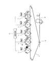
図4は、本発明の第2の実施の形態における画像形成装置の要部構成例を示す説明図である。
図例の画像形成装置も、第1の実施の形態の場合と同様に、複数の像形成部12〜15,17が一列に並設された、いわゆる「タンデム方式」のものである。
ただし、図例の画像形成装置は、透明色材であるクリアートナーを用いて像形成を行う像形成部17が、1つのみ設けられている点で、第1の実施の形態の場合とは異なる。この1つの像形成部17は、各像形成部12〜15,17のうちで、中間体ベルト21の搬送方向の最上流側に位置するように配されている。
つまり、図例の画像形成装置は、具体的には5つの像形成部12〜15,17を備えていることになる。
<Second Embodiment>
Next, an image forming apparatus according to a second embodiment of the present invention will be described.
FIG. 4 is an explanatory diagram showing a configuration example of a main part of the image forming apparatus according to the second embodiment of the present invention.
The image forming apparatus shown in the figure is also of the so-called “tandem system” in which a plurality of
However, the image forming apparatus shown in the figure is different from the case of the first embodiment in that only one
That is, the image forming apparatus shown in the figure specifically includes five
また、図例の画像形成装置では、クリアートナーを用いて像形成を行う像形成部17が1つのみであるのに伴い、制御装置24による像形成順の制御態様が、第1の実施の形態の場合とは異なる。
Further, in the image forming apparatus shown in the figure, since there is only one
なお、他の構成要素については、第1の実施の形態の場合と同様であるため、ここではその説明を省略する。 Since the other components are the same as those in the first embodiment, the description thereof is omitted here.
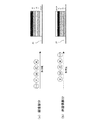
図5は、本発明の第2の実施の形態における像形成順に関する動作制御の具体例を示す説明図である。 FIG. 5 is an explanatory diagram showing a specific example of the operation control relating to the image forming order in the second embodiment of the present invention.
図5(a)に示すように、画像部分についての像形成を行う場合に、制御装置24は、中間体ベルト21の一周目において、クリアートナーによるトナー像を形成する像形成部17、Y色のカラートナーによるトナー像を形成する像形成部12、M色のカラートナーによるトナー像を形成する像形成部13、C色のカラートナーによるトナー像を形成する像形成部14、および、K色のカラートナーによるトナー像を形成する像形成部15に対して、像形成を行うように動作指示を与える。これにより、中間体ベルト21上には、当該中間体ベルト21上の像形成領域が各像形成部11〜16における一次転写装置を順に通過することにより、当該中間体ベルト21の側からクリアートナーによるトナー像、Y色のトナー像、M色のトナー像、C色のトナー像、および、K色のトナー像が順に積層されることになる。
As shown in FIG. 5A, when image formation is performed on an image portion, the
また、図5(b)に示すように、非画像部分についての像形成を行う場合に、制御装置24は、中間体ベルト21の一周目において、クリアートナーによるトナー像を形成する像形成部17に対して、像形成の指示を与えない。そして、当該一周目において、Y色のカラートナーによるトナー像を形成する像形成部12、M色のカラートナーによるトナー像を形成する像形成部13、C色のカラートナーによるトナー像を形成する像形成部14、および、K色のカラートナーによるトナー像を形成する像形成部15に対して、画像部分についての動作指示を与えた後に、中間体ベルト21が二周目にはいると、クリアートナーによるトナー像を形成する像形成部17に対して、像形成を行うように動作指示を与える。これにより、中間体ベルト21上には、当該中間体ベルト21上の像形成領域が各像形成部11〜16における一次転写装置を順に通過することにより、当該中間体ベルト21の側からY色のトナー像、M色のトナー像、C色のトナー像、K色のトナー像、および、クリアートナーによるトナー像が順に積層されることになる。
Further, as shown in FIG. 5B, when image formation is performed on a non-image portion, the
つまり、制御装置24は、像形成順に関する動作制御にあたり、画像部分についてはクリアートナーの後にカラートナーを用いる形成順とする。一方、非画像部分については最後にクリアートナーを用いる形成順とする。このように、画像部分と非画像部分とで、クリアートナーとカラートナーの形成順を相違させるのである。
In other words, the
以上のように、第2の実施の形態における構成の画像形成装置においても、第1の実施の形態の場合と同様に、画像部分と非画像部分とで、クリアートナーとカラートナーの形成順が相違している。
したがって、図3(a)を用いて説明したように、画像部分では、カラートナーの層が効率よく用紙上に転写されることになる一方で、非画像部分については、カブリトナーの用紙上への転写が抑制されることになる。しかも、画像部分と非画像部分のいずれにもクリアートナーの層が位置していることから、用紙上へのカラートナー像の転写後においては、当該用紙上における転写像の光沢感について画像部分と非画像部分で差が生じてしまうことがない。
As described above, also in the image forming apparatus having the configuration according to the second embodiment, the order of forming the clear toner and the color toner is different between the image portion and the non-image portion as in the case of the first embodiment. It is different.
Therefore, as described with reference to FIG. 3A, the color toner layer is efficiently transferred onto the paper in the image portion, while the non-image portion is onto the fog toner paper. The transfer of is suppressed. Moreover, since the clear toner layer is located in both the image portion and the non-image portion, after the color toner image is transferred onto the paper, the glossiness of the transferred image on the paper is There is no difference between non-image parts.
また、第2の実施の形態における構成の画像形成装置では、透明色材であるクリアートナーを用いて像形成を行う1つの像形成部17を備えている。そして、中間体ベルト21の一周目と二周目との亘り、当該1つの像形成部17が像形成を行うように構成されている。つまり、上述した像形成順に関する動作制御を制御装置24が行う場合には、中間体ベルト21の複数周(具体的には、二周。)の間、すなわちいわゆるスキッププロセスを含む2パスプロセスで、1つの像形成部17が当該中間体ベルト21上への像形成を行うことになる。したがって、画像部分と非画像部分とでクリアートナーとカラートナーの形成順を相違させる場合であっても、クリアートナーを用いて像形成を行う像形成部17の配設数が1つのみで済む。
In addition, the image forming apparatus having the configuration according to the second embodiment includes one
<第3の実施の形態>
次に、本発明の第3の実施の形態における画像形成装置について説明する。
図6は、本発明の第3の実施の形態における画像形成装置の要部構成例を示す説明図である。
図例の画像形成装置は、像形成部18の構成が、第1または第2の実施の形態の場合とは異なる。すなわち、図例の画像形成装置は、1つの像形成部18が配設された、いわゆる「ロータリ方式」のものである。
<Third Embodiment>
Next, an image forming apparatus according to a third embodiment of the present invention will be described.
FIG. 6 is an explanatory diagram illustrating an exemplary configuration of a main part of an image forming apparatus according to the third embodiment of the present invention.
In the illustrated image forming apparatus, the configuration of the
像形成部18は、カラー画像対応のために、1つの感光体ドラム18Dに対して複数の現像器18CT,18Y,18M,18C,18Kが配されて構成されている。各現像器18CT,18Y,18M,18C,18Kの中には、有色色材であるカラートナーを用いて像形成を行うものの他に、透明色材であるクリアートナーを用いて像形成を行うものが含まれている。つまり、像形成部18は、Y色のトナー像を現像する現像器18Y、M色のトナー像を現像する現像器18M、C色のトナー像を現像する現像器18C、K色のトナー像を現像する現像器18K、および、クリアートナー像を現像する現像器18CTを備えており、これらが選択的に感光体ドラム18D上の潜像に対する現像を行うように構成されている。
なお、像形成部18における他の構成要素である帯電器、露光装置、一次転写装置、クリーニング装置等については、公知であるため、ここではその説明を省略する。
The
Note that other components in the
像形成部18以外の構成要素である中間体ベルト21、二次転写装置22および定着器23については、第1または第2の実施の形態の場合と同様である。
The
第3の実施の形態における画像形成装置では、像形成部18がロータリ方式のものであることから、制御装置24が像形成部18に対して、以下に述べるような像形成順の動作制御を行う。
In the image forming apparatus according to the third embodiment, since the
図7は、本発明の第3の実施の形態における像形成順に関する動作制御の具体例を示す説明図である。 FIG. 7 is an explanatory diagram showing a specific example of operation control related to the image formation order in the third embodiment of the present invention.
感光体ドラム18Dの一周目に、制御装置24は、クリアートナー像を現像する現像器18CTに対して、画像部分についての像形成を行うように動作指示を与える。これにより、感光体ドラム18D上に形成されたクリアートナー像は、当該感光体ドラム18Dの一周目、すなわち中間体ベルト21の一周目に、当該中間体ベルト21上に転写される。
感光体ドラム18Dの二周目に、制御装置24は、Y色のトナー像を現像する現像器18Yに対して像形成を行うように動作指示を与える。これにより、感光体ドラム18D上に形成されたY色のトナー像は、当該感光体ドラム18Dの二周目、すなわち中間体ベルト21の二周目に、当該中間体ベルト21上に転写される。
感光体ドラム18Dの三周目に、制御装置24は、M色のトナー像を現像する現像器18Mに対して像形成を行うように動作指示を与える。これにより、感光体ドラム18D上に形成されたM色のトナー像は、当該感光体ドラム18Dの三周目、すなわち中間体ベルト21の三周目に、当該中間体ベルト21上に転写される。
感光体ドラム18Dの四周目に、制御装置24は、C色のトナー像を現像する現像器18Cに対して像形成を行うように動作指示を与える。これにより、感光体ドラム18D上に形成されたC色のトナー像は、当該感光体ドラム18Dの四周目、すなわち中間体ベルト21の四周目に、当該中間体ベルト21上に転写される。
感光体ドラム18Dの五周目に、制御装置24は、K色のトナー像を現像する現像器18Kに対して像形成を行うように動作指示を与える。これにより、感光体ドラム18D上に形成されたK色のトナー像は、当該感光体ドラム18Dの五周目、すなわち中間体ベルト21の五周目に、当該中間体ベルト21上に転写される。
感光体ドラム18Dの六周目に、制御装置24は、再びクリアートナー像を現像する現像器18CTに対して、今度は非画像部分についての像形成を行うように動作指示を与える。これにより、感光体ドラム18D上に形成されたクリアートナー像は、当該感光体ドラム18Dの六周目、すなわち中間体ベルト21の六周目に、当該中間体ベルト21上に転写される。
In the first round of the
On the second turn of the
On the third turn of the
On the fourth turn of the
On the fifth turn of the
On the sixth turn of the
以上のような一連の処理動作を経ることで、中間体ベルト21上では、画像部分については、当該中間体ベルト21の側からクリアートナーによるトナー像、Y色のトナー像、M色のトナー像、C色のトナー像、および、K色のトナー像が順に積層されることになる。一方、非画像部分については、当該中間体ベルト21の側からY色のトナー像、M色のトナー像、C色のトナー像、K色のトナー像、および、クリアートナーによるトナー像が順に積層されることになる。
Through a series of processing operations as described above, on the
つまり、制御装置24は、像形成順に関する動作制御にあたり、画像部分についてはクリアートナーの後にカラートナーを用いる形成順とする。一方、非画像部分については最後にクリアートナーを用いる形成順とする。このように、画像部分と非画像部分とで、クリアートナーとカラートナーの形成順を相違させるのである。
In other words, the
以上のように、第3の実施の形態における構成の画像形成装置においても、第1または第2の実施の形態の場合と同様に、画像部分と非画像部分とで、クリアートナーとカラートナーの形成順が相違している。
したがって、図3(a)を用いて説明したように、画像部分では、カラートナーの層が効率よく用紙上に転写されることになる一方で、非画像部分については、カブリトナーの用紙上への転写が抑制されることになる。しかも、画像部分と非画像部分のいずれにもクリアートナーの層が位置していることから、用紙上へのカラートナー像の転写後においては、当該用紙上における転写像の光沢感について画像部分と非画像部分で差が生じてしまうことがない。
As described above, in the image forming apparatus having the configuration according to the third embodiment, the clear toner and the color toner are separated between the image portion and the non-image portion as in the case of the first or second embodiment. The order of formation is different.
Therefore, as described with reference to FIG. 3A, the color toner layer is efficiently transferred onto the paper in the image portion, while the non-image portion is onto the fog toner paper. The transfer of is suppressed. Moreover, since the clear toner layer is located in both the image portion and the non-image portion, after the color toner image is transferred onto the paper, the glossiness of the transferred image on the paper is There is no difference between non-image parts.
また、第3の実施の形態における構成の画像形成装置では、ロータリ方式に対応しており、クリアートナー像を現像する現像器▽を備えた1つの像形成部18を備えている。そして、感光体ドラム18Dおよび中間体ベルト21が複数周する間に、当該1つの像形成部18が像形成を行うように構成されている。したがって、画像部分と非画像部分とでクリアートナーとカラートナーの形成順を相違させる場合であっても、クリアートナーを用いて像形成を行う現像器▽および像形成部18の配設数が1つのみで済む。
Further, the image forming apparatus having the configuration according to the third embodiment is compatible with the rotary system, and includes one
なお、上述した第1〜第3の実施の形態では、本発明の好適な実施具体例について説明したが、本発明はその内容に限定されるものではない。
例えば、各実施形態では、YMCKの各色トナーを用いてカラー画像の形成出力を行う場合を例に挙げて説明したが、本発明がこれに限定されないことは勿論である。すなわち、本発明は、カラー対応機のみならず、白黒対応機についても、全く同様に適用することが考えられる。
つまり、本発明は、上述した各実施の形態で説明した内容に限定されるものではなく、その要旨を逸脱しない範囲で適宜変更してもよい。
In the first to third embodiments described above, preferred specific examples of the present invention have been described. However, the present invention is not limited to the contents.
For example, in each embodiment, the case where a color image is formed and output using YMCK color toners has been described as an example, but the present invention is not limited to this. That is, the present invention can be applied to not only a color compatible machine but also a monochrome compatible machine.
That is, the present invention is not limited to the contents described in each of the above-described embodiments, and may be appropriately changed without departing from the gist thereof.
11〜18…像形成部、18D…感光体ドラム、18CT,18Y,18M,18C,18K…現像器、21…中間体ベルト、22…二次転写装置、23…定着器、24…制御装置 DESCRIPTION OF SYMBOLS 11-18 ... Image formation part, 18D ... Photosensitive drum, 18CT, 18Y, 18M, 18C, 18K ... Developing device, 21 ... Intermediate belt, 22 ... Secondary transfer device, 23 ... Fixing device, 24 ... Control device
Claims (4)
前記像保持体上の像形成領域における画像部分と非画像部分で前記透明色材と前記有色色材の形成順を相違させる形成順制御手段と、
前記像保持体上に形成された像を記録媒体上に転写する転写手段と
を備えることを特徴とする画像形成装置。 An image forming means for forming an image on an image carrier using a transparent color material and a color material;
Formation order control means for making the formation order of the transparent color material and the colored color material different in the image part and the non-image part in the image forming region on the image carrier;
An image forming apparatus comprising: transfer means for transferring an image formed on the image carrier onto a recording medium.
前記非画像部分は、最後に前記透明色材を用いる形成順とする
ことを特徴とする請求項1記載の画像形成装置。 The image portion is formed in the order in which the colored color material is used after the transparent color material,
The image forming apparatus according to claim 1, wherein the non-image portion is formed in the order in which the transparent color material is used last.
前記画像部分のために前記透明色材による像形成を行う第1透明像形成部と、
前記非画像部分のために前記透明色材による像形成を行う第2透明像形成部とを備え、
前記像保持体の一周の間に前記第1透明像形成部と前記第2透明像形成部とのそれぞれが当該像保持体上への像形成を行うように構成されている
ことを特徴とする請求項1または2記載の画像形成装置。 The image forming means includes:
A first transparent image forming unit that forms an image with the transparent color material for the image portion;
A second transparent image forming unit that forms an image with the transparent color material for the non-image part,
Each of the first transparent image forming unit and the second transparent image forming unit is configured to form an image on the image holding member during one round of the image holding member. The image forming apparatus according to claim 1.
前記透明色材による像形成を行う1つの透明像形成部を備え、
前記像保持体の複数周の間に前記1つの透明像形成部が前記画像部分のための当該像保持体上への像形成と前記非画像部分のための当該像保持体上への像形成とのそれぞれを行うように構成されている
ことを特徴とする請求項1または2記載の画像形成装置。 The image forming means includes:
Comprising one transparent image forming unit for performing image formation with the transparent color material,
The one transparent image forming unit forms an image on the image carrier for the image portion and forms an image on the image carrier for the non-image portion during a plurality of circumferences of the image carrier. The image forming apparatus according to claim 1, wherein the image forming apparatus is configured to perform each of the following.
Priority Applications (3)
| Application Number | Priority Date | Filing Date | Title |
|---|---|---|---|
| JP2009025559A JP5234281B2 (en) | 2009-02-06 | 2009-02-06 | Image forming apparatus |
| US12/547,994 US8351825B2 (en) | 2009-02-06 | 2009-08-26 | Image forming apparatus and image forming method |
| CN200910173906.2A CN101799645B (en) | 2009-02-06 | 2009-09-17 | Image forming apparatus and image forming method |
Applications Claiming Priority (1)
| Application Number | Priority Date | Filing Date | Title |
|---|---|---|---|
| JP2009025559A JP5234281B2 (en) | 2009-02-06 | 2009-02-06 | Image forming apparatus |
Publications (2)
| Publication Number | Publication Date |
|---|---|
| JP2010181663A true JP2010181663A (en) | 2010-08-19 |
| JP5234281B2 JP5234281B2 (en) | 2013-07-10 |
Family
ID=42540512
Family Applications (1)
| Application Number | Title | Priority Date | Filing Date |
|---|---|---|---|
| JP2009025559A Expired - Fee Related JP5234281B2 (en) | 2009-02-06 | 2009-02-06 | Image forming apparatus |
Country Status (3)
| Country | Link |
|---|---|
| US (1) | US8351825B2 (en) |
| JP (1) | JP5234281B2 (en) |
| CN (1) | CN101799645B (en) |
Cited By (4)
| Publication number | Priority date | Publication date | Assignee | Title |
|---|---|---|---|---|
| JP2012242780A (en) * | 2011-05-24 | 2012-12-10 | Konica Minolta Business Technologies Inc | Image forming apparatus and image forming method |
| JP2016031469A (en) * | 2014-07-29 | 2016-03-07 | 株式会社沖データ | Printing system and image forming apparatus |
| JP2019184642A (en) * | 2018-04-02 | 2019-10-24 | 富士ゼロックス株式会社 | Image forming apparatus |
| JP2022148768A (en) * | 2021-03-24 | 2022-10-06 | 株式会社リコー | Image forming apparatus |
Families Citing this family (7)
| Publication number | Priority date | Publication date | Assignee | Title |
|---|---|---|---|---|
| US8101326B2 (en) * | 2006-05-19 | 2012-01-24 | Eastman Kodak Company | Secure document printing method and system |
| US8619329B2 (en) | 2010-11-12 | 2013-12-31 | Xerox Corporation | Print smoothness on clear toner enabled systems |
| JP5906658B2 (en) | 2011-10-20 | 2016-04-20 | 株式会社リコー | Image forming apparatus and image forming method |
| WO2015023262A1 (en) * | 2013-08-13 | 2015-02-19 | Hewlett-Packard Development Company, L.P. | Pattern foil printing |
| KR102111425B1 (en) * | 2016-02-24 | 2020-06-04 | 가부시키가이샤 리코 | Image processing apparatus, image processing system and program |
| JP7077700B2 (en) * | 2018-03-22 | 2022-05-31 | 富士フイルムビジネスイノベーション株式会社 | Image formation system |
| JP2025054706A (en) * | 2023-09-26 | 2025-04-08 | 富士フイルムビジネスイノベーション株式会社 | Electrostatic image developing toner set, electrostatic image developer set, toner cartridge set, process cartridge, image forming apparatus, and image forming method |
Citations (9)
| Publication number | Priority date | Publication date | Assignee | Title |
|---|---|---|---|---|
| JPS6358374A (en) * | 1986-08-29 | 1988-03-14 | Fuji Xerox Co Ltd | Image forming method |
| JP2002116631A (en) * | 2000-10-04 | 2002-04-19 | Konica Corp | Image forming device |
| JP2002214871A (en) * | 2001-01-16 | 2002-07-31 | Konica Corp | Image forming device |
| JP2005037582A (en) * | 2003-07-18 | 2005-02-10 | Ricoh Co Ltd | Full color image forming apparatus |
| JP2006030737A (en) * | 2004-07-20 | 2006-02-02 | Canon Inc | Image forming apparatus |
| JP2006171100A (en) * | 2004-12-13 | 2006-06-29 | Canon Inc | Image forming apparatus |
| JP2006215196A (en) * | 2005-02-02 | 2006-08-17 | Fuji Xerox Co Ltd | Image forming method and image forming device |
| JP2006220740A (en) * | 2005-02-08 | 2006-08-24 | Fuji Xerox Co Ltd | Image forming method and image forming apparatus |
| JP2007052068A (en) * | 2005-08-15 | 2007-03-01 | Fuji Xerox Co Ltd | Image forming apparatus |
Family Cites Families (4)
| Publication number | Priority date | Publication date | Assignee | Title |
|---|---|---|---|---|
| JP2002207334A (en) | 2001-01-11 | 2002-07-26 | Konica Corp | Image forming device |
| JP2006156075A (en) * | 2004-11-29 | 2006-06-15 | Seiko Epson Corp | Electro-optical device manufacturing method and image forming apparatus |
| ITBL20050001A1 (en) * | 2005-01-14 | 2006-07-15 | Fedon Giorgio & Figli S P A | PROCEDURE FOR GRAPHIC DECORATION OF SURFACES WITH SUBLIMATIC INKS AND PROTECTIVE RESINS. |
| KR20080061749A (en) * | 2006-12-28 | 2008-07-03 | 삼성전자주식회사 | Printing method of electrophotographic image forming apparatus employing transparent toner |
-
2009
- 2009-02-06 JP JP2009025559A patent/JP5234281B2/en not_active Expired - Fee Related
- 2009-08-26 US US12/547,994 patent/US8351825B2/en not_active Expired - Fee Related
- 2009-09-17 CN CN200910173906.2A patent/CN101799645B/en not_active Expired - Fee Related
Patent Citations (9)
| Publication number | Priority date | Publication date | Assignee | Title |
|---|---|---|---|---|
| JPS6358374A (en) * | 1986-08-29 | 1988-03-14 | Fuji Xerox Co Ltd | Image forming method |
| JP2002116631A (en) * | 2000-10-04 | 2002-04-19 | Konica Corp | Image forming device |
| JP2002214871A (en) * | 2001-01-16 | 2002-07-31 | Konica Corp | Image forming device |
| JP2005037582A (en) * | 2003-07-18 | 2005-02-10 | Ricoh Co Ltd | Full color image forming apparatus |
| JP2006030737A (en) * | 2004-07-20 | 2006-02-02 | Canon Inc | Image forming apparatus |
| JP2006171100A (en) * | 2004-12-13 | 2006-06-29 | Canon Inc | Image forming apparatus |
| JP2006215196A (en) * | 2005-02-02 | 2006-08-17 | Fuji Xerox Co Ltd | Image forming method and image forming device |
| JP2006220740A (en) * | 2005-02-08 | 2006-08-24 | Fuji Xerox Co Ltd | Image forming method and image forming apparatus |
| JP2007052068A (en) * | 2005-08-15 | 2007-03-01 | Fuji Xerox Co Ltd | Image forming apparatus |
Cited By (5)
| Publication number | Priority date | Publication date | Assignee | Title |
|---|---|---|---|---|
| JP2012242780A (en) * | 2011-05-24 | 2012-12-10 | Konica Minolta Business Technologies Inc | Image forming apparatus and image forming method |
| JP2016031469A (en) * | 2014-07-29 | 2016-03-07 | 株式会社沖データ | Printing system and image forming apparatus |
| JP2019184642A (en) * | 2018-04-02 | 2019-10-24 | 富士ゼロックス株式会社 | Image forming apparatus |
| JP2022148768A (en) * | 2021-03-24 | 2022-10-06 | 株式会社リコー | Image forming apparatus |
| JP7594737B2 (en) | 2021-03-24 | 2024-12-05 | 株式会社リコー | Image forming device |
Also Published As
| Publication number | Publication date |
|---|---|
| CN101799645B (en) | 2014-11-19 |
| US8351825B2 (en) | 2013-01-08 |
| CN101799645A (en) | 2010-08-11 |
| US20100202789A1 (en) | 2010-08-12 |
| JP5234281B2 (en) | 2013-07-10 |
Similar Documents
| Publication | Publication Date | Title |
|---|---|---|
| JP5234281B2 (en) | Image forming apparatus | |
| JP5043524B2 (en) | Image forming apparatus | |
| JP2016133529A (en) | Image forming apparatus | |
| JP4962534B2 (en) | Image forming apparatus | |
| JP2009020281A (en) | Waste developer collecting device for image forming apparatus, and image forming apparatus | |
| JP2011191504A (en) | Image forming apparatus | |
| JP2005024936A (en) | Image forming apparatus | |
| JP2006201385A (en) | Image forming apparatus | |
| JP2006221106A (en) | Image forming apparatus | |
| JP2007240814A (en) | Image forming apparatus and image forming method | |
| JP5617206B2 (en) | Image forming apparatus | |
| JP2014119632A (en) | Image forming apparatus | |
| JP5183816B2 (en) | Image forming apparatus | |
| JP2014178349A (en) | Image forming apparatus, image forming program, and image forming method | |
| JP4198567B2 (en) | Wet color image forming apparatus | |
| JP2005010389A (en) | Image forming apparatus | |
| JP2009128811A (en) | Image forming apparatus | |
| JP2009063768A (en) | Image forming apparatus and control method for image forming apparatus | |
| JP6142981B2 (en) | Image forming apparatus | |
| JP2007240893A (en) | Image forming apparatus | |
| JP2006235290A (en) | Image forming apparatus | |
| JP2007017779A (en) | Color image forming apparatus | |
| JP2009128810A (en) | Image forming apparatus | |
| JP2017032643A (en) | Transfer unit and image forming apparatus having the same | |
| JP5211969B2 (en) | Image forming apparatus, toner collecting method, and computer program |
Legal Events
| Date | Code | Title | Description |
|---|---|---|---|
| A621 | Written request for application examination |
Free format text: JAPANESE INTERMEDIATE CODE: A621 Effective date: 20120123 |
|
| A131 | Notification of reasons for refusal |
Free format text: JAPANESE INTERMEDIATE CODE: A131 Effective date: 20121217 |
|
| A977 | Report on retrieval |
Free format text: JAPANESE INTERMEDIATE CODE: A971007 Effective date: 20121219 |
|
| A521 | Request for written amendment filed |
Free format text: JAPANESE INTERMEDIATE CODE: A523 Effective date: 20130213 |
|
| TRDD | Decision of grant or rejection written | ||
| A01 | Written decision to grant a patent or to grant a registration (utility model) |
Free format text: JAPANESE INTERMEDIATE CODE: A01 Effective date: 20130227 |
|
| A61 | First payment of annual fees (during grant procedure) |
Free format text: JAPANESE INTERMEDIATE CODE: A61 Effective date: 20130312 |
|
| R150 | Certificate of patent or registration of utility model |
Free format text: JAPANESE INTERMEDIATE CODE: R150 Ref document number: 5234281 Country of ref document: JP Free format text: JAPANESE INTERMEDIATE CODE: R150 |
|
| FPAY | Renewal fee payment (event date is renewal date of database) |
Free format text: PAYMENT UNTIL: 20160405 Year of fee payment: 3 |
|
| LAPS | Cancellation because of no payment of annual fees |