JP2010178982A5 - - Google Patents
Download PDFInfo
- Publication number
- JP2010178982A5 JP2010178982A5 JP2009026326A JP2009026326A JP2010178982A5 JP 2010178982 A5 JP2010178982 A5 JP 2010178982A5 JP 2009026326 A JP2009026326 A JP 2009026326A JP 2009026326 A JP2009026326 A JP 2009026326A JP 2010178982 A5 JP2010178982 A5 JP 2010178982A5
- Authority
- JP
- Japan
- Prior art keywords
- attachment
- mode
- acceleration
- clip
- detachment
- Prior art date
- Legal status (The legal status is an assumption and is not a legal conclusion. Google has not performed a legal analysis and makes no representation as to the accuracy of the status listed.)
- Granted
Links
- 230000001133 acceleration Effects 0.000 description 116
- 238000001514 detection method Methods 0.000 description 78
- 238000000034 method Methods 0.000 description 51
- 230000000694 effects Effects 0.000 description 34
- 210000000614 Ribs Anatomy 0.000 description 31
- 210000001624 Hip Anatomy 0.000 description 28
- 230000000875 corresponding Effects 0.000 description 12
- 238000005259 measurement Methods 0.000 description 7
- 230000035939 shock Effects 0.000 description 4
- 238000010586 diagram Methods 0.000 description 3
- 230000005540 biological transmission Effects 0.000 description 2
- 239000000203 mixture Substances 0.000 description 2
- 230000002093 peripheral Effects 0.000 description 2
- 235000019577 caloric intake Nutrition 0.000 description 1
- 210000000038 chest Anatomy 0.000 description 1
- 230000001771 impaired Effects 0.000 description 1
- 238000009434 installation Methods 0.000 description 1
- 239000004973 liquid crystal related substance Substances 0.000 description 1
- 238000000926 separation method Methods 0.000 description 1
Images
Description
この発明は、例えば生体の歩数を計数する歩数計や生体の活動量を測定する活動量計など、生体の体動を検出するような体動検出装置に関する。 The present invention relates to a body motion detection device that detects body motion of a living body, such as a pedometer that counts the number of steps of a living body and an activity meter that measures the amount of activity of a living body.
従来、生体の体動を検出する装置として、歩数計や活動量計など、種々の体動検出装置が提案されている。これらの体動検出装置は、様々な場所に装着あるいは収納して使用することが提案されている。 Conventionally, various body motion detection devices such as a pedometer and an activity meter have been proposed as devices for detecting body motion of a living body. These body motion detection devices have been proposed to be used by being mounted or housed in various places.
例えば、腰のベルトや洋服の胸ポケット等にクリップで挟んで装着する歩数計が提案されている(特許文献1参照)。このようにクリップで挟んで装着する方法は、装着方向が定まっているために安定した歩数計測が可能という利点がある。 For example, there has been proposed a pedometer that is attached to a waist belt, a chest pocket of clothes, or the like with a clip (see Patent Document 1). In this way, the mounting method sandwiched between clips has the advantage that stable step count measurement is possible because the mounting direction is fixed.
しかし、この方法は、クリップで挟むことのできる場所がある服装に限定されるという問題点、および、歩数計が目立つために使用者のファッション性を損なうという問題がある。 However, this method has a problem that it is limited to clothes that can be sandwiched between clips, and a problem that the fashionability of the user is impaired because the pedometer is conspicuous.
また、腕時計型をしており、ベルトによって腕に装着する振子式の運動量計が提案されている(特許文献2参照)。このベルトにより腕に装着する方法は、服装が限定されないという利点と、使用者が表示内容を見やすい利点がある。 In addition, a pendulum-type exercise meter that has a wristwatch type and is attached to an arm by a belt has been proposed (see Patent Document 2). The method of wearing on the arm with this belt has the advantage that the clothes are not limited and the advantage that the user can easily see the displayed contents.
しかし、この方法は、腕をしっかり振る活動でなければ計測できず、日常使用において用途が限定されるという問題点がある。 However, this method cannot be measured unless it is an activity of shaking the arm firmly, and there is a problem that the application is limited in daily use.
また、複数軸のセンサを用いることによって本体が傾いた状態でも歩数計測を可能とし、洋服や鞄のポケットに入れて携帯することのできる体動検出装置が提案されている(特許文献3参照)。この複数軸のセンサを用いる方法は、携帯性に優れるという利点がある。 Also, a body motion detection device has been proposed that can measure the number of steps even when the main body is tilted by using a multi-axis sensor and can be carried in a pocket of clothes or a bag (see Patent Document 3). . This method using a multi-axis sensor has an advantage of excellent portability.
しかし、この方法は、傾いた状態での計測を行なうため、様々な体動の影響を受けやすく、高い精度で幅広い範囲の活動に対応させることが困難であるという問題点がある。 However, since this method performs measurement in a tilted state, it is susceptible to various body movements and it is difficult to cope with a wide range of activities with high accuracy.
このように、いずれの装着態様で体動検出装置を使用しても利点と問題点が存在し、一つの装着態様では全てを解決することはできなかった。 As described above, there are advantages and problems even if the body motion detection device is used in any of the wearing modes, and all of them cannot be solved by one wearing mode.
この発明は、上述した問題点に鑑み、どの装着態様で用いられるか検出し、さらに検出した装着態様に適したモードで体動を検出することにより、使用態様の自由度を向上するとともに測定精度を向上することを目的とする。 In view of the above-described problems, the present invention improves the degree of freedom of the usage mode and the measurement accuracy by detecting which mounting mode is used and detecting body movement in a mode suitable for the detected mounting mode. The purpose is to improve.
この発明は、加速度を検出する加速度検出手段と、前記加速度検出手段により検出した加速度データに基づいて生体の体動を算出する体動算出処理を実行する演算手段とを備えた体動検出装置であって、生体または生体連動物品に装着される装着体が装置本体に着脱されることを許容する着脱部を備え、前記演算手段は、前記着脱部に前記装着体を着脱する際に前記加速度データに現れる加速度の変化から着脱を検出する着脱検出処理を実行し、検出した着脱に基づいて前記体動算出処理を着脱後の状態に合うモードに切り替えて実行する構成である体動検出装置であることを特徴とする。 The present invention is a body motion detection device comprising acceleration detection means for detecting acceleration and calculation means for executing body motion calculation processing for calculating body motion of a living body based on acceleration data detected by the acceleration detection means. And an attachment / detachment unit that allows the attachment body attached to the living body or the biological interlocking article to be attached / detached to / from the apparatus main body, and the calculation unit is configured to perform the acceleration data when attaching / detaching the attachment body to / from the attachment / detachment unit Is a body motion detection device configured to execute attachment / detachment detection processing for detecting attachment / detachment from a change in acceleration appearing in the vehicle, and to switch the body motion calculation processing to a mode suitable for the state after attachment / detachment based on the detected attachment / detachment. It is characterized by that.
前記加速度検出手段は、加速度検出センサなど、加速度の変化を検出することができる手段で構成することができる。加速度検出センサとする場合、一次元、二次元、あるいは三次元の加速度センサとすることができるが、三次元の加速度センサとすることが好ましい。 The acceleration detection means can be constituted by means capable of detecting a change in acceleration, such as an acceleration detection sensor. In the case of the acceleration detection sensor, a one-dimensional, two-dimensional, or three-dimensional acceleration sensor can be used, but a three-dimensional acceleration sensor is preferable.
前記体動算出処理は、歩数を計数する歩数計数処理、生活活動量を算出する生活活動量算出処理、腕振りレベルを算出する腕振りレベル算出処理、あるいはこれらの複数の処理とすることができる。 The body motion calculation process may be a step count process for counting the number of steps, a life activity amount calculation process for calculating a daily activity amount, an arm swing level calculation process for calculating an arm swing level, or a plurality of these processes. .
前記生体連動物品は、ズボンやスカートなどの下衣または腰ベルトとすることができる。
前記装着体は、ズボンやスカートなどの下衣または腰ベルトに取り付けるためのクリップなどの挟持具、あるいは腕や足などに取り付けるためのベルトなど、生体または生体連動物品に装着される器具で構成することができる。
The biological interlocking article may be a garment such as trousers or a skirt or a waist belt.
The wearing body is constituted by a device attached to a living body or a living body interlocking article such as a garment such as a clip for attaching to a lower garment such as pants or a skirt or a waist belt, or a belt for attaching to an arm or a leg. be able to.
前記装置本体は、加速度検出手段と演算手段とを備えた筐体とすることができる。
前記着脱部は、装着体に設けられた所定の着脱係合部が着脱される適宜のガイド、突起、ネジ山、ネジ溝、孔、または溝などによる係合部で構成することができる。
The apparatus main body may be a casing provided with acceleration detection means and calculation means.
The attachment / detachment portion can be constituted by an engagement portion such as an appropriate guide, protrusion, screw thread, screw groove, hole, or groove to / from which a predetermined attachment / detachment engagement portion provided on the mounting body is attached / detached.
前記着脱検出処理は、本体装置に装着体を着脱する際に生じる衝突による加速度変化を検出する処理、着脱部のガイドに沿った装置本体の移動や回転による加速度の変化を検出する処理、あるいはこれらの組合せなど、着脱の際に生じる加速度変化を検出する処理で構成することができる。 The attachment / detachment detection process includes a process for detecting an acceleration change due to a collision that occurs when the attachment body is attached to or detached from the main body apparatus, a process for detecting a change in acceleration due to movement or rotation of the apparatus body along the guide of the attachment / detachment part, or these It can be configured by a process for detecting an acceleration change that occurs during attachment / detachment, such as a combination of the above.
前記モードは、腰装着モード、腕装着モード、ポケットインモード、またはこれらの複数とすることができる。これらのモードの切替の際、算出する体動を歩数、生活活動量、または腕振りレベルなどから切り替える、体動の算出に用いる閾値を切り替える、あるいはこの両方を実施することができる。 The mode may be a waist wearing mode, an arm wearing mode, a pocket-in mode, or a plurality of these. When switching between these modes, the calculated body motion can be switched from the number of steps, the amount of daily activity, the arm swing level, or the like, the threshold used for calculating the body motion, or both can be implemented.
前記体動検出装置は、歩数をカウントする歩数計、生活活動量を算出する活動量計、あるいは歩数と生活活動量を算出する運動量計など、適宜の装置とすることができる。この体動検出装置には、表示手段や通信手段などの出力手段を設けてもよい。この出力手段により、加速度信号または検出した体動データを出力してもよい。 The body motion detection device may be an appropriate device such as a pedometer that counts the number of steps, an activity meter that calculates the amount of daily activity, or an exercise meter that calculates the number of steps and the amount of daily activity. The body movement detection device may be provided with output means such as display means and communication means. The output means may output an acceleration signal or detected body motion data.
この発明により、装着体の着脱を検出し、着脱後の状態に合うモードで体動を検出することができる。従って、どのような装着態様で使用するかという使用態様の自由度を向上することができ、各使用態様に応じてモード切り替えすることにより測定精度を向上することができる。 According to the present invention, it is possible to detect attachment / detachment of a wearing body and detect body movement in a mode suitable for the state after attachment / detachment. Accordingly, it is possible to improve the degree of freedom of the usage mode in which mounting mode is used, and to improve the measurement accuracy by switching the mode according to each usage mode.
この発明の態様として、前記着脱部は、前記装着体の着脱時に該装着体の一部が衝突する衝突体が設けられ、前記着脱検出処理は、前記衝突体に前記装着体の一部が衝突して現れる加速度の変化を前記加速度データから検出する構成とすることができる。 As an aspect of the present invention, the attachment / detachment unit includes a collision body that collides with a part of the mounting body when the mounting body is attached / detached, and the attachment / detachment detection process includes a collision of a part of the mounting body with the collision body. The change of the acceleration that appears can be detected from the acceleration data.
前記衝突体は、前記装着体の一部が衝突する突起、孔、溝、または壁など、衝突可能な適宜の部位で構成することができ、装置本体の筐体と一体形成する、あるいは別部材を固着して構成することができる。 The collision body can be configured with an appropriate part capable of colliding, such as a projection, hole, groove, or wall with which a part of the mounting body collides, and is formed integrally with the casing of the apparatus main body or as a separate member Can be fixed.
前記装着体の一部は、前記衝突体が衝突する突起、孔、溝、または壁など、衝突可能な適宜の部位で構成することができ、装着体の筐体と一体形成する、あるいは別部材を固着して構成することができる。 A part of the mounting body can be formed of an appropriate part capable of colliding, such as a projection, hole, groove, or wall with which the collision body collides, and is formed integrally with the housing of the mounting body or is a separate member. Can be fixed.
この態様により、歩行や走行、腕振り、生活活動といった生体の運動では現れない加速度の変化を装置本体と装着体の着脱時に発生させることができ、加速度検出手段が着脱を精度よく検出することができる。 According to this aspect, a change in acceleration that does not appear in living body movement such as walking, running, arm swing, and daily activities can be generated when the apparatus main body and the attachment body are attached / detached, and the acceleration detecting means can detect attachment / detachment with high accuracy. it can.
またこの発明の態様として、前記着脱部は、複数種類の装着体に個別対応して複数設けることができる。
複数種類の装着体に個別対応して複数設ける着脱部は、例えば着脱方向を異ならせたレールや溝などのガイドを用いて構成する、あるいは同一の着脱方向で平行して設け前記衝突体の個数や配置が異なるように構成するなど、各種の装着体によって着脱する部位が異なるように構成することができる。
この態様により、どの種類の装着体が着脱されたのかを容易に検出することができる。
Moreover, as an aspect of this invention, the said attachment / detachment part can be provided with two or more individually corresponding to several types of mounting body.
A plurality of attachment / detachment portions provided individually corresponding to a plurality of types of mounting bodies are configured using, for example, guides such as rails and grooves with different attachment / detachment directions, or provided in parallel in the same attachment / detachment direction. It can be configured such that the parts to be attached and detached are different depending on various mounting bodies, such as being configured so that the arrangement is different.
According to this aspect, it is possible to easily detect which type of mounting body has been attached or detached.
またこの発明の態様として、前記着脱検出処理は、前記衝突体に前記装着体の一部が衝突して現れる加速度の変化の方向によって着脱された該装着体の種類を検出する構成とすることができる。 Further, as an aspect of the present invention, the attachment / detachment detection process is configured to detect the type of the attachment body attached / detached according to the direction of change in acceleration that appears when a part of the attachment body collides with the collision body. it can.
これにより、どの種類の装着体が着脱されたのかを加速度の変化の方向によって精度よく検出することができる。 As a result, it is possible to accurately detect which type of mounting body has been attached or detached based on the direction of change in acceleration.
またこの発明の態様として、前記着脱部は、対応する前記装着体の種類別に前記衝突体の個数を異ならせて構成され、前記着脱検出処理は、前記衝突体に前記装着体の一部が衝突して現れる加速度の変化の数によって着脱された該装着体の種類を検出する構成とすることができる。 Further, as an aspect of the present invention, the attaching / detaching portion is configured by changing the number of the collision bodies according to the type of the corresponding attachment body, and the attachment / detachment detection process includes a part of the attachment body colliding with the collision body. The type of the attached / detached body can be detected based on the number of acceleration changes that appear.
これにより、どの種類の装着体が着脱されたのかを衝突回数によって精度よく検出することができる。特に、前記衝突体に前記装着体の一部が衝突して現れる加速度の変化の方向によって着脱された該装着体の種類を検出する構成と組み合わせれば、加速度の変化の方向と衝突回数によってより精度よく着脱された装着体の種類を検出することができる。 As a result, it is possible to accurately detect which type of mounting body has been attached and detached based on the number of collisions. In particular, when combined with a configuration that detects the type of the mounting body that is attached and detached according to the direction of the change in acceleration that appears when a part of the mounting body collides with the collision body, it depends on the direction of change in acceleration and the number of collisions. It is possible to detect the type of the attached body that is attached and detached with high accuracy.
またこの発明は、加速度を検出する加速度検出手段と、データを記憶する記憶手段と、前記加速度検出手段により検出した加速度データに基づいて生体の体動を算出する体動算出処理を実行する演算手段と、演算結果を表示する表示手段とを備えた体動検出装置であって、生体または生体連動物品に装着される装着体が装置本体に着脱されることを許容する着脱部を前記装着体の種類別に複数備え、前記演算手段は、前記着脱部に対して前記装着体が着脱されたときに前記加速度データに現れる加速度の変化によって前記着脱部に対する前記装着体の着脱と該装着体の種類とを検出する着脱検出処理を実行し、検出した着脱と種類とに基づいて前記体動算出処理を着状態の装着体の種類に対応するモードに切り替えて実行する構成であり、前記表示手段は、該モードに対応する画面を表示する構成である体動検出装置とすることができる。 The present invention also provides an acceleration detection means for detecting acceleration, a storage means for storing data, and a calculation means for executing a body motion calculation process for calculating a body motion of a living body based on acceleration data detected by the acceleration detection means. And a display means for displaying the calculation result, and a detachable portion that allows the attachment body attached to the living body or the biological interlocking article to be attached to or detached from the apparatus main body. A plurality of types are provided, and the computing means attaches and detaches the mounting body to and from the detachable portion according to a change in acceleration that appears in the acceleration data when the mounting body is attached to and detached from the detachable portion. The body movement calculation process is executed by switching to a mode corresponding to the type of the wearing body in the wearing state based on the detected attachment and detachment and type. Display means may be a movement detecting device is configured to display a screen corresponding to the mode.
前記モードに対応する画面は、腰装着モードであることを示す画面、腕装着モードであることを示す画面、あるいはポケットインモードであることを示す画面など、モードに対応する画面で構成することができる。 The screen corresponding to the mode may be configured with a screen corresponding to the mode, such as a screen indicating the waist wearing mode, a screen indicating the arm wearing mode, or a screen indicating the pocket-in mode. it can.
この発明により、現在どのモードとなっているかを利用者が容易に確認することができる。 According to the present invention, the user can easily confirm which mode is currently set.
またこの発明の態様として、生体の体動を検出する体動検出装置であって、生体または生体連動物品に装着される装着体が装置本体に着脱されることを許容する着脱部を備え、該着脱部は、前記装着体が装置本体に着脱される際に該装着体をスライドまたは回転させるガイドと、該ガイドに沿って前記装着体が着脱される際に該装着体の一部に衝突する衝突部とを備えた体動検出装置とすることができる。 Further, as an aspect of the present invention, there is provided a body motion detection device for detecting a body motion of a living body, including an attachment / detachment unit that allows the attachment body attached to the living body or the biological interlocking article to be attached to and detached from the apparatus body, The attachment / detachment unit collides with a guide that slides or rotates the attachment body when the attachment body is attached to or detached from the apparatus main body, and a part of the attachment body when the attachment body is attached / detached along the guide. It can be set as the body movement detection apparatus provided with the collision part.
前記ガイドは、レール、溝、ネジ山、あるいはネジ溝など、装着体を着脱する際のスライドまたは回転を規制する部材で構成することができる。 The guide may be formed of a member that regulates sliding or rotation when attaching and detaching the mounting body, such as a rail, a groove, a screw thread, or a screw groove.
この発明により、着脱時の装置本体と装着体との相対移動を定めることができ、着脱の検出を容易にすることができる。 According to the present invention, the relative movement between the apparatus main body and the mounting body at the time of attachment / detachment can be determined, and the attachment / detachment can be easily detected.
またこの発明は、加速度を検出する加速度検出手段と、該加速度検出手段により検出した加速度データに基づく演算を実行する演算手段と、該加速度検出手段および前記演算手段を収納する筐体とを備えた入力装置であって、前記筐体は、衝突による衝撃が付与される衝突体が設けられ、前記演算手段は、前記加速度データから前記衝突体に付与された衝撃によって加速度変化が生じた衝撃加速度データを検出し、該衝撃加速度データから衝撃の付与された衝撃内容を検出し、該衝撃内容によって入力された情報を決定する入力情報決定処理を実行する構成である入力装置とすることができる。 The present invention also includes acceleration detection means for detecting acceleration, calculation means for executing calculation based on acceleration data detected by the acceleration detection means, and a casing for housing the acceleration detection means and the calculation means. In the input device, the casing is provided with a collision body to which an impact due to a collision is applied, and the calculation means is an impact acceleration data in which an acceleration change is generated by the impact applied to the collision body from the acceleration data. The input device can be configured to detect the shock content to which the shock has been applied from the shock acceleration data, and to execute input information determination processing for determining information input according to the shock content.
前記衝撃内容は、衝撃の方向、回数、間隔、強度の少なくとも1つとすることができる。
入力された情報は、モードを切り替えるモード切替情報、あるいは所定の入力指示を示す入力指示情報など、適宜の情報とすることができる。なお、入力装置には、決定した入力情報を出力する出力手段(表示手段や通信手段など)を設けてもよい。
The impact content may be at least one of impact direction, number of times, interval, and strength.
The input information can be appropriate information such as mode switching information for switching modes or input instruction information indicating a predetermined input instruction. The input device may be provided with output means (display means, communication means, etc.) for outputting the determined input information.
衝撃加速度データは、前記衝突体に衝撃が加えられたことによって生じる加速度変化による加速度データとすることができる。従って、加速度検出手段で検出する加速度データには、この衝撃加速度データと、入力装置全体を揺する、移動させる、あるいは回転させるといった動作によって生じた加速度変化を示す通常加速度データとが混在する。
この発明により、衝突体に対する衝撃から入力情報を決定することができる。特に体動検出装置にこの入力装置を採用した場合、加速度検出手段により、体動検出に加えて体動検出以外の入力も検出することができる。
The impact acceleration data can be acceleration data based on an acceleration change caused by an impact applied to the collision object. Accordingly, the acceleration data detected by the acceleration detecting means includes a mixture of the impact acceleration data and normal acceleration data indicating acceleration changes caused by operations such as shaking, moving, or rotating the entire input device.
According to the present invention, the input information can be determined from the impact on the collision object. In particular, when this input device is employed in a body motion detection device, the acceleration detection means can detect inputs other than body motion detection in addition to body motion detection.
またこの発明は、生体の体動により生じた加速度の変化を示す加速度データから前記生体の体動を検出する体動検出方法であって、装置本体に対して装着体が着脱される際に生じる加速度の変化を前記加速度データから検出し、該着脱後の状態に対応するモードの体動検出処理により該着脱後の加速度データから体動を検出する体動検出方法とすることができる。 The present invention is also a body motion detection method for detecting body motion of the living body from acceleration data indicating a change in acceleration caused by the body motion of the living body, and occurs when the mounting body is attached to and detached from the apparatus main body. It is possible to provide a body motion detection method in which a change in acceleration is detected from the acceleration data, and body motion is detected from the acceleration data after attachment / detachment by a body motion detection process in a mode corresponding to the state after attachment / detachment.
これにより、加速度データから装着体の着脱を検出することができ、またその着脱後の加速度データから装着体の着脱状態に応じたモードで体動を検出することができる。 Thereby, attachment / detachment of the wearing body can be detected from the acceleration data, and body movement can be detected from the acceleration data after the attachment / detachment in a mode corresponding to the attachment / detachment state of the wearing body.
従って、例えば加速度検出手段とデータ送信手段とを備えた体動検出用保持装置から別途の情報処理装置(コンピュータ、携帯情報端末、またはサーバなど)が加速度データを受信し、この情報処理装置で体動を検出することができる。 Therefore, for example, a separate information processing device (computer, portable information terminal, server, etc.) receives acceleration data from the body motion detection holding device including the acceleration detection means and the data transmission means, and the body is received by this information processing device. Motion can be detected.
この場合、サーバ等が加速度データを受け取って該加速度データから体動を精度よく検出する、あるいは、運動のアドバイスを行うインストラクターが情報処理装置によって精度よく検出された体動を確認し運動している利用者にアドバイスするなど、様々な態様で利用することができる。 In this case, the server or the like receives acceleration data and accurately detects body movement from the acceleration data, or an instructor who gives exercise advice confirms the body movement accurately detected by the information processing apparatus and is exercising. It can be used in various ways, such as advising the user.
この発明により、どの装着態様で用いられるか検出し、さらに検出した装着態様に適したモードで体動を検出することにより、使用態様の自由度を向上するとともに測定精度を向上することができる。特に、着脱部のハードウェア構成とソフトウェア処理を組み合わせて装着態様を検出するため、簡潔な構成で確実に装着態様を検出することができる。 According to the present invention, it is possible to improve the degree of freedom of the usage mode and the measurement accuracy by detecting which mounting mode is used and detecting the body movement in a mode suitable for the detected mounting mode. In particular, since the mounting mode is detected by combining the hardware configuration of the detachable unit and software processing, the mounting mode can be reliably detected with a simple configuration.
この発明の一実施形態を以下図面と共に説明する。 An embodiment of the present invention will be described below with reference to the drawings.
実施例1では、腕に装着して使用する腕装着モード、腰に装着して使用する腰装着モード、およびポケットに収納して使用するポケットインモードの3モードに対応する運動量計について説明する。 In the first embodiment, a momentum meter corresponding to three modes of an arm wearing mode used by wearing on an arm, a waist wearing mode used by wearing on a waist, and a pocket-in mode used by storing in a pocket will be described.
図1は、正面側から見た運動量計1の分解斜視図を示し、図2は、背面側から見た運動量計1の分解斜視図を示し、図3は運動量計1の各状態を斜視図により説明する説明図を示す。 1 shows an exploded perspective view of the momentum 1 viewed from the front side, FIG. 2 shows an exploded perspective view of the momentum 1 viewed from the back side, and FIG. 3 is a perspective view showing each state of the momentum 1. Explanatory drawing demonstrated by these is shown.
運動量計1は、運動量計本体3と、該運動量計本体3に着脱可能なベルト型装着体2およびクリップ型装着体4とで構成されている。 The exercise meter 1 includes an exercise meter main body 3, a belt-type attachment body 2 and a clip-type attachment body 4 that can be attached to and detached from the exercise amount main body 3.
運動量計本体3は、図示の例では厚手の略円盤形状に形成されており、図1に示すように正面に表示部13が設けられ、図2に示すように背面に4つの着脱ガイド31と2つの衝突突起33と1つの裏蓋36とが設けられている。 The exercise meter body 3 is formed in a thick and substantially disk shape in the illustrated example, and is provided with a display unit 13 on the front side as shown in FIG. 1 and four attachment / detachment guides 31 on the back side as shown in FIG. Two collision protrusions 33 and one back cover 36 are provided.
着脱ガイド31は、運動量計本体3の裏面中心から等距離の位置に4箇所均等に配置されており、いずれも同形状に形成されている。各着脱ガイド31は、運動量計本体3の裏面に固着された基部31aの外周サイズより先端部31bの外周サイズが大きい2段の略三角柱形状に形成されている。これにより、基部31aの側面で先端部31bと運動量計本体3の裏面との間がクリップ用ガイド凹部31cとバンド用ガイド凹部31dとして機能する。 The attachment / detachment guides 31 are equally arranged at four positions at equidistant positions from the center of the back surface of the momentum body 3, and all are formed in the same shape. Each of the attachment / detachment guides 31 is formed in a two-stage substantially triangular prism shape in which the outer peripheral size of the distal end portion 31b is larger than the outer peripheral size of the base portion 31a fixed to the back surface of the momentum meter main body 3. Thereby, between the front-end | tip part 31b and the back surface of the momentum main body 3 functions as the clip guide recessed part 31c and the band guide recessed part 31d on the side surface of the base part 31a.
また、クリップ用ガイド凹部31c,31cの間位置の一方と、バンド用ガイド凹部31d,31dの間位置の一方には、クリップ用およびバンド用の各衝突突起33,33が設けられている。 Further, at one of the positions between the clip guide recesses 31c and 31c and one of the positions between the band guide recesses 31d and 31d, the clip and band collision protrusions 33 and 33 are provided.
裏蓋36は、電池を収納する開閉可能な蓋であり、運動量計本体3の背面中央に設けられている。この裏蓋36は、運動量計本体3にベルト型装着体2やクリップ型装着体4が装着されて覆われている状態では開くことができず、運動量計本体3からベルト型装着体2やクリップ型装着体4を取り外した状態でのみ開くことができる。これにより、電池が交換されるとき、運動量計本体3は、装着体(2,4)の取り付けられていない単体状態に必ずなる構成になっている。 The back cover 36 is an openable / closable cover for storing the battery, and is provided in the center of the back surface of the exercise meter main body 3. This back cover 36 cannot be opened in a state in which the belt-type mounting body 2 or the clip-type mounting body 4 is mounted on the momentum meter body 3 and is covered. It can be opened only with the mold mounting body 4 removed. Thereby, when a battery is replaced | exchanged, the momentum main body 3 becomes a structure which will be surely in the single-piece | unit state to which the mounting body (2, 4) is not attached.
ベルト型装着体2は、利用者の腕に装着するためのリング状のベルト部25と、該ベルト部25の一部に設けられて外側に運動量計本体3を着脱するマウント部21とで構成されている。 The belt-type mounting body 2 includes a ring-shaped belt portion 25 for mounting on a user's arm, and a mount portion 21 that is provided on a part of the belt portion 25 and attaches / detaches the momentum body 3 to the outside. Has been.
マウント部21は、図1に示すように、外側の面に2本の平行のレールで構成されるガイドレール22,22が設けられ、このガイドレール22,22の間に橋渡しされた複数の突起状のリブ23が取付方向(矢印X方向)に多段に設けられている。 As shown in FIG. 1, the mount portion 21 is provided with guide rails 22, 22 composed of two parallel rails on the outer surface, and a plurality of protrusions bridged between the guide rails 22, 22. The ribs 23 are provided in multiple stages in the mounting direction (arrow X direction).
リブ23は、ガイドレール22による運動量計本体3の着脱方向に対して直角で運動量計本体3とマウント部21の対向面に対して平行となる棒状または板状に形成されている。また、このリブ23は、着脱時にガイドレール22が運動量計本体3のバンド用ガイド凹部31dに係合してスライド移動する移動距離内に複数設けられている。これにより、リブ23が装着体側衝突体として機能し、運動量計本体3に設けられた本体側衝突体としての衝突突起33がスライド移動中に複数のリブ23に衝突する構成となっている。なお、この2本のガイドレール22と複数のリブ23により、梯子のごとき形状が形成されている。 The ribs 23 are formed in a bar shape or a plate shape that is perpendicular to the direction in which the momentum meter body 3 is attached and detached by the guide rails 22 and is parallel to the opposing surfaces of the momentum body 3 and the mount portion 21. Further, a plurality of ribs 23 are provided within a moving distance in which the guide rail 22 engages with the band guide recess 31d of the momentum meter body 3 and slides during attachment / detachment. Thereby, the rib 23 functions as a mounting body side collision body, and the collision protrusion 33 as the main body side collision body provided in the momentum body 3 collides with the plurality of ribs 23 during the sliding movement. The two guide rails 22 and the plurality of ribs 23 form a shape like a ladder.
クリップ型装着体4は、運動量計本体3を着脱するマウント部41と、該マウント部41の裏面側で利用者のベルトやズボンやスカート等を挟み込むクリップ部45とで構成されている。 The clip-type mounting body 4 includes a mount portion 41 that attaches and detaches the momentum body 3 and a clip portion 45 that sandwiches a user's belt, trousers, skirt, or the like on the back side of the mount portion 41.
マウント部41は、図1に示すように、外側の面に2本の平行のレールで構成されるガイドレール42,42が設けられ、このガイドレール42,42の間に橋渡しされた複数の突起状のリブ43が取付方向(矢印Y方向)に多段に設けられている。 As shown in FIG. 1, the mount portion 41 is provided with guide rails 42, 42 composed of two parallel rails on the outer surface, and a plurality of protrusions bridged between the guide rails 42, 42. The ribs 43 are provided in multiple stages in the mounting direction (arrow Y direction).
リブ43は、ガイドレール42による運動量計本体3の着脱方向に対して直角で運動量計本体3とマウント部41の対向面に対して平行となる棒状または板状に形成されている。また、このリブ43は、着脱時にガイドレール42が運動量計本体3のクリップ用ガイド凹部31cに係合してスライド移動する移動距離内に複数設けられている。これにより、リブ43が装着体側衝突体として機能し、運動量計本体3の衝突突起33がスライド移動中に複数のリブ43に衝突する構成となっている。なお、この2本のガイドレール42と複数のリブ43により、梯子のごとき形状が形成されている。 The rib 43 is formed in a bar shape or a plate shape that is perpendicular to the attaching / detaching direction of the momentum meter body 3 by the guide rail 42 and parallel to the opposing surfaces of the momentum meter body 3 and the mount portion 41. A plurality of ribs 43 are provided within a moving distance in which the guide rail 42 engages with the clip guide recess 31c of the momentum meter body 3 and slides during attachment / detachment. Thereby, the rib 43 functions as a mounting body side collision body, and the collision projection 33 of the momentum body 3 collides with the plurality of ribs 43 during the sliding movement. The two guide rails 42 and the plurality of ribs 43 form a shape like a ladder.
この構成により、運動量計本体3は、図3(A1)(A2)に示すようにベルト型装着体2を取り付けて腕装着型として利用する、図3(B1)(B2)に示すようにクリップ型装着体4を取り付けて腰装着型として利用する、あるいは図3(C1)(C2)に示すようにベルト型装着体2とクリップ型装着体4のどちらも取り付けずにポケットイン型として利用することの3態様が可能になる。 With this configuration, the exercise meter body 3 is used as an arm-mounted type by attaching the belt-type mounting body 2 as shown in FIGS. 3A1 and 3A2, and as shown in FIGS. 3B1 and 3B2. A type mounting body 4 is attached and used as a waist mounting type, or as shown in FIGS. 3 (C1) and (C2), neither a belt type mounting body 2 nor a clip type mounting body 4 is used as a pocket-in type. Three aspects of this are possible.
図4は、運動量計1の構成を示すブロック図である。
運動量計1は、加速度検知部12、表示部13、演算部14、電源接続部15、記憶部16、操作部17、および電源部18を有しており、携帯型とするべく普通人の手のひらに納まる程度の大きさに形成されている。
FIG. 4 is a block diagram showing the configuration of the exercise meter 1.
The exercise meter 1 includes an acceleration detection unit 12, a display unit 13, a calculation unit 14, a power supply connection unit 15, a storage unit 16, an operation unit 17, and a power supply unit 18, and is designed to be portable. It is formed to a size that fits in
加速度検知部12は、運動量計1を装着した利用者の歩行や体動等によって生じる振動の加速度を検知するセンサであり、検知信号を演算部14に伝達する。この加速度検知部12は、直交する三方向の加速度を検知する三次元加速度センサで構成されている。この加速度検知部12は、検知する3方向を、運動量計本体3の前後方向、左右方向、および上下方向に正しく合わせて運動量計本体3に配置されている。これにより、前後方向、左右方向、および上下方向の各加速度成分を容易かつ精度良く抽出することができる。また、この左右方向に平行にスライドするようにバンド用ガイド凹部31d(図2参照)が形成され、上下方向に平行にスライドするようにクリップ用ガイド凹部31c(図2参照)が形成されているため、ベルト型装着体2やクリップ型装着体4の取り付け、取り外しも精度良く検出することができる。 The acceleration detection unit 12 is a sensor that detects acceleration of vibration caused by walking or body movement of a user wearing the exercise meter 1, and transmits a detection signal to the calculation unit 14. The acceleration detection unit 12 includes a three-dimensional acceleration sensor that detects acceleration in three orthogonal directions. This acceleration detector 12 is arranged in the momentum meter body 3 so that the three directions to be detected are correctly aligned with the front-rear direction, the left-right direction, and the up-down direction of the momentum meter body 3. Thereby, each acceleration component of the front-back direction, the left-right direction, and the up-down direction can be extracted easily and accurately. Further, a band guide recess 31d (see FIG. 2) is formed so as to slide parallel to the left-right direction, and a clip guide recess 31c (see FIG. 2) is formed so as to slide parallel to the up-down direction. Therefore, the attachment and detachment of the belt-type attachment body 2 and the clip-type attachment body 4 can also be detected with high accuracy.
表示部13は、液晶などの表示機器で構成されており、演算部14からの表示制御信号に従って情報を表示する。この表示する情報は、歩数、生活活動量、腕振りレベル、現在のモードなど、運動量に関する情報とすることができる。 The display unit 13 is composed of a display device such as a liquid crystal, and displays information according to a display control signal from the calculation unit 14. The information to be displayed can be information related to the amount of exercise such as the number of steps, the amount of daily activity, the arm swing level, and the current mode.
演算部14は、電源部18から電源接続部15を介して受け取る電力によって駆動し、加速度検知部12および操作部17から伝達される検知信号の受け取り(検出)、表示部13、および記憶部16に対する電力供給(電源)と動作制御(表示制御)を実行する。また、加速度検知部12から伝達された検知信号に基づいて、記憶部16に記憶している歩行判定基準データや一歩判定基準データ等を参照して演算する処理も実行する。 The calculation unit 14 is driven by power received from the power supply unit 18 via the power supply connection unit 15, receives (detects) detection signals transmitted from the acceleration detection unit 12 and the operation unit 17, the display unit 13, and the storage unit 16. Power supply (power supply) and operation control (display control) are executed. Further, based on the detection signal transmitted from the acceleration detection unit 12, a process of calculating with reference to the walking determination reference data and the one-step determination reference data stored in the storage unit 16 is also executed.
記憶部16は、加速度検知部12で検知した検知信号である加速度データ、該加速度データからベルト型装着体2およびクリップ型装着体4の着脱を検出して測定モードを切り替える全体プログラム、ベルト型装着体2が装着されている際に実行する腕装着体動検出プログラム、クリップ型装着体4が装着されている際に実行する腰装着体動検出プログラム、ベルト型装着体2もクリップ型装着体4も装着されていない場合に実行するポケットイン体動検出プログラム、腕装着体動検出プログラムが用いる腕装着モードパラメータ、腰装着体動検出プログラムが用いる腰装着モードパラメータ、およびポケットイン体動検出プログラムが用いるポケットインモードパラメータ、および算出した歩数や歩行外活動量など、必要なプログラムとデータを記憶する。 The storage unit 16 includes acceleration data that is a detection signal detected by the acceleration detection unit 12, an overall program that detects attachment / detachment of the belt-type mounting body 2 and the clip-type mounting body 4 from the acceleration data, and switches the measurement mode, and belt-type mounting Arm wearing body movement detection program executed when the body 2 is worn, waist wearing body movement detection program executed when the clip type wearing body 4 is worn, and the belt type wearing body 2 are also clip type wearing bodies 4 A pocket-in body motion detection program, an arm-mounted mode parameter used by the arm-mounted body motion detection program, a waist-mounted mode parameter used by the waist-mounted body motion detection program, and a pocket-in body motion detection program. Necessary programs and data, such as the pocket-in mode parameters used, the calculated number of steps and the amount of extra-walking activity And stores the data.
操作部17は、体重や歩幅などの利用者情報の入力操作、時計を合わせる日時入力操作、および、表示内容を歩数・消費カロリー・歩行距離といった各種内容に切り替える表示内容切替操作など、適宜の操作入力を受け付け、この操作入力信号を演算部14に伝達する。
電源部18は、充電可能なバッテリーや充電不可の電池など、携帯可能な適宜の電源により構成されている。
The operation unit 17 performs appropriate operations such as an input operation of user information such as weight and stride, a date input operation for setting a clock, and a display content switching operation for switching display contents to various contents such as the number of steps, calorie consumption, and walking distance. An input is received and this operation input signal is transmitted to the calculation unit 14.
The power supply unit 18 is configured by an appropriate portable power source such as a rechargeable battery or a non-chargeable battery.
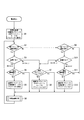
図5は、記憶部16に記憶されている全体プログラムに従って運動量計1の演算部14が実行する動作を示すフローチャートである。
演算部14は、電源の投入(電池の装着)を受けて、初期化処理を実行する(ステップS1)。この初期化処理では、演算用パラメータをポケットインモードパラメータに設定する処理も実行する。この初期化処理が完了した後、演算部14は、加速度検知部12で検知した加速度データに対して種々の処理(ステップS2〜S12)を実行していく。
FIG. 5 is a flowchart showing an operation executed by the calculation unit 14 of the exercise meter 1 in accordance with the entire program stored in the storage unit 16.
The calculation unit 14 receives an input of power (installation of a battery) and executes an initialization process (step S1). In this initialization process, a process for setting a calculation parameter as a pocket-in mode parameter is also executed. After the initialization process is completed, the calculation unit 14 performs various processes (steps S2 to S12) on the acceleration data detected by the acceleration detection unit 12.
演算部14は、加速度検知部12で検知した加速度データに基づいて、クリップ型装着体4の着脱の有無を検知する(ステップS2)。
このクリップ型装着体4の着脱の有無は、運動量計本体3にクリップ型装着体4が着脱される際に、運動量計本体3の衝突突起33にクリップ型装着体4のリブ43が衝突して現れる加速度の変化から検知する。
The calculating part 14 detects the presence or absence of attachment or detachment of the clip type mounting body 4 based on the acceleration data detected by the acceleration detection part 12 (step S2).
Whether or not the clip-type mounting body 4 is attached / detached is determined by the rib 43 of the clip-type mounting body 4 colliding with the collision protrusion 33 of the momentum body 3 when the clip-type mounting body 4 is attached to or detached from the momentum body 3. Detect from changes in acceleration that appears.
詳述すると、例えばクリップ型装着体4を装着するとき、図6(A)に示すようにクリップ型装着体4と運動量計本体3をスライド移動させると、運動量計本体3の衝突突起33は、図6(B)に示すように、クリップ型装着体4のリブ43に衝突しつつ該リブ43を乗り越える。この衝突して乗り越える際に、図7のグラフに示すように、Y方向(運動量計本体3の上下方向)の一方(図示の例では正方向)にのみ突出する鋭い波形P(所定の時間内に所定の範囲の強さが現れる波形)が、リブ43に衝突突起33が衝突した回数に応じて現れる。このように正または負の一方にだけに突出する鋭い波形は、通常の歩行や生活活動や腕振りでは現れない波形であるから、運動によるものではなく着脱によるものであることが明確である。この波形を検知することで、演算部14は、クリップ型装着体4の着脱を検出することができる。 More specifically, for example, when the clip-type mounting body 4 is mounted, if the clip-type mounting body 4 and the momentum body 3 are slid as shown in FIG. As shown in FIG. 6 (B), the rib 43 is ridden while colliding with the rib 43 of the clip-type mounting body 4. At the time of overcoming by this collision, as shown in the graph of FIG. 7, a sharp waveform P (within a predetermined time) protruding only in one direction (positive direction in the illustrated example) in the Y direction (up and down direction of the momentum body 3). (A waveform in which the strength of a predetermined range appears) corresponds to the number of times the collision projection 33 collides with the rib 43. In this way, the sharp waveform protruding only in one of the positive and negative directions is a waveform that does not appear in normal walking, daily activities, and arm swinging, so it is clear that it is not due to exercise but due to attachment / detachment. By detecting this waveform, the calculation unit 14 can detect the attachment / detachment of the clip-type mounting body 4.
クリップ型装着体4の着脱を検知すると(ステップS2:Yes)、演算部14は、その着脱が装着方向(正方向)か否かを判定する(ステップS3)。この装着方向の判定をする演算部14は、加速度検知部12で検出した波形PがY方向(上下方向)に正(上向き)であれば取り付け、負(下向き)であれば取り外しと判定する。 When the attachment / detachment of the clip-type attachment 4 is detected (step S2: Yes), the calculation unit 14 determines whether the attachment / detachment is in the attachment direction (forward direction) (step S3). The calculation unit 14 that determines the mounting direction determines that the waveform is detected if the waveform P detected by the acceleration detection unit 12 is positive (upward) in the Y direction (vertical direction), and is removed if the waveform P is negative (downward).
装着方向(取り付け)であれば(ステップS3:Yes)、演算部14は、現在のモードが腰装着モードであるか否かを判定する(ステップS4)。
腰装着モードでなければ(ステップS4:No)、演算部14は、演算用パラメータを腰装着モードパラメータに設定する(ステップS5)。このとき、演算部14は、体動を演算するプログラムも腰装着体動検出プログラムに切り替え、腰装着モードへ完全に移行する。このステップS4〜S5により、運動量計本体3にクリップ型装着体4が取り付けられればすぐに腰装着モードに移行するようにしている。
If it is the mounting direction (attachment) (step S3: Yes), the calculation unit 14 determines whether or not the current mode is the waist mounting mode (step S4).
If it is not the waist mounting mode (step S4: No), the calculation unit 14 sets the calculation parameter to the waist mounting mode parameter (step S5). At this time, the calculation unit 14 switches the body motion calculation program to the waist-mounted body motion detection program, and completely shifts to the waist-mounted mode. As a result of steps S4 to S5, as soon as the clip-type mounting body 4 is attached to the exercise meter body 3, the mode is shifted to the waist mounting mode.
演算部14は、設定されているパラメータを用い、切り替えられた体動検出プログラムで体動演算処理を実行し(ステップS6)、ステップS2に処理を戻して繰り返す。この体動演算処理の詳細は、モード別に後述する。 The calculation unit 14 executes the body motion calculation process with the switched body motion detection program using the set parameters (step S6), and returns to step S2 to repeat the process. Details of the body motion calculation process will be described later for each mode.
前記ステップS4で腰装着モードであれば(ステップS4:Yes)、演算部14は、そのまま体動演算処理(ステップS6)を実行する。 If it is waist mounting mode at the step S4 (step S4: Yes), the calculation unit 14 executes the body movement calculation process (step S6) as it is.
ステップS3で着脱が装着方向(正方向)でなければ(ステップS3:No)、取り外しであるから、演算部14は、現在のモードがポケットインモードか否かを判定する(ステップS7)。 If attachment / detachment is not the attachment direction (forward direction) in step S3 (step S3: No), since it is removal, the calculating part 14 determines whether the present mode is pocket-in mode (step S7).
演算部14は、ポケットインモードでなければ(ステップS7:No)、演算用パラメータをポケットインモードパラメータにすると共に体動検出プログラムをポケットイン体動検出プログラムに切り替え(ステップS8)、ステップS6へ処理を進める。 If the calculation unit 14 is not in the pocket-in mode (step S7: No), the calculation parameter is changed to the pocket-in mode parameter, the body motion detection program is switched to the pocket-in body motion detection program (step S8), and the process proceeds to step S6. Proceed with the process.
ポケットインモードであれば(ステップS7:Yes)、演算部14はそのままステップS6へ処理を進める。このステップS7〜S8により、運動量計本体3からクリップ型装着体4が外されればすぐにポケットインモードに戻るようにしている。 If it is pocket-in mode (step S7: Yes), the calculating part 14 will advance a process to step S6 as it is. By these steps S7 to S8, when the clip-type mounting body 4 is removed from the exercise meter body 3, the pocket-in mode is immediately restored.
ステップS2でクリップ型装着体4の着脱を検出しなかった場合(ステップS2:No)、演算部14は、ベルト型装着体2の着脱の検出を実行する(ステップS9)。この着脱は、上述した鋭い波形P(図7参照)がX方向(左右方向)に現れるか否かにより検出する。 When the attachment / detachment of the clip-type attachment body 4 is not detected in step S2 (step S2: No), the calculation unit 14 detects the attachment / detachment of the belt-type attachment body 2 (step S9). This attachment / detachment is detected based on whether or not the sharp waveform P described above (see FIG. 7) appears in the X direction (left-right direction).
着脱を検出しなかった場合(ステップS9:No)、モード変更が必要ないため、演算部14は、そのまま体動演算処理(ステップS6)に処理を進める。 When the attachment / detachment is not detected (step S9: No), since the mode change is not necessary, the calculation unit 14 proceeds to the body motion calculation process (step S6) as it is.
ベルト型装着体2の着脱を検出した場合(ステップS9:Yes)、演算部14は、その着脱が装着方向(正方向)か否かを判定する(ステップS10)。この装着方向の判定をする演算部14は、加速度検知部12で検出した波形PがX方向(左右方向)に正(背面視左向き)であれば取り付け、負(背面視右向き)であれば取り外しと判定する。 When the attachment / detachment of the belt-type attachment body 2 is detected (step S9: Yes), the calculation unit 14 determines whether the attachment / detachment is in the attachment direction (forward direction) (step S10). The calculation unit 14 for determining the mounting direction is attached if the waveform P detected by the acceleration detection unit 12 is positive (leftward in the rear view) in the X direction (left-right direction), and is removed if negative (leftward in the rear view). Is determined.
着脱が装着方向(正方向)でなければ(ステップS10:No)、取り外しであるから、演算部14は、上述したステップS7〜S8を実行してポケットインモードにモード変更した後に体動演算処理(ステップS6)へ処理を進める。 If the attachment / detachment is not the attachment direction (positive direction) (step S10: No), since the attachment is removal, the computation unit 14 executes steps S7 to S8 described above to change the mode to the pocket-in mode, and then performs the body movement computation process. The process proceeds to (Step S6).
着脱が装着方向(取り付け)であれば(ステップS10:Yes)、演算部14は、現在のモードが腕装着モードであるか否かを判定する(ステップS11)。
腕装着モードでなければ(ステップS11:No)、演算部14は、演算用パラメータを腕装着モードパラメータに設定し(ステップS12)、体動演算処理(ステップS6)へ処理を進める。
If the attachment / detachment is the attachment direction (attachment) (step S10: Yes), the calculation unit 14 determines whether or not the current mode is the arm attachment mode (step S11).
If it is not the arm wearing mode (step S11: No), the calculation unit 14 sets the calculation parameter to the arm wearing mode parameter (step S12), and proceeds to the body movement calculation process (step S6).
この腕装着モードパラメータに設定するとき、演算部14は、体動を演算するプログラムも腕装着体動検出プログラムに切り替え、腕装着モードへ完全に移行する。このステップS11〜S12により、運動量計本体3にベルト型装着体2が取り付けられればすぐに腕装着モードに移行するようにしている。 When the arm wearing mode parameter is set, the computing unit 14 switches the body motion calculating program to the arm wearing body motion detecting program and completely shifts to the arm wearing mode. As a result of steps S11 to S12, as soon as the belt-type mounting body 2 is attached to the exercise meter body 3, the arm mounting mode is shifted to.
図8は、腰装着モードで腰装着体動検出プログラムに従って体動演算処理を実行する演算部14の動作を示すフローチャートである。 FIG. 8 is a flowchart showing the operation of the calculation unit 14 that executes body motion calculation processing in accordance with the waist mounting body motion detection program in the waist mounting mode.
演算部14は、3次元の加速度検知部12で検出したXYZ加速度の加速度データを取得する(ステップS21)。このあと、演算部14は、歩数計数処理(ステップS22〜S23)と生活活動量算出処理(ステップS24〜S26)とを並列に処理する。 The calculation unit 14 acquires acceleration data of the XYZ acceleration detected by the three-dimensional acceleration detection unit 12 (step S21). Then, the calculating part 14 processes a step count process (steps S22-S23) and a daily activity amount calculation process (steps S24-S26) in parallel.
歩数計数処理を実行する演算部14は、加速度データから歩数を算出する(ステップS22)。このとき、演算部14は、腰装着モードパラメータを用いて歩数を算出する。これにより、腰に装着されている状態に適したパラメータで歩数を計数できるため、精度の良い歩数検出ができる。 The computing unit 14 that executes the step count processing calculates the step count from the acceleration data (step S22). At this time, the calculation unit 14 calculates the number of steps using the waist wearing mode parameter. Thereby, since the number of steps can be counted with parameters suitable for the state worn on the waist, it is possible to detect the number of steps with high accuracy.
演算部14は、算出した歩数を表示部13に腰装着モード表示画面13bとして表示し(ステップS23)、体動演算処理を終了する。このときの腰装着モード表示画面13bは、図3(B1)に示したように、腰装着モードであることを示す「Activity Monitor Mode」、本日の合計歩数を示す「9758 steps」、本日の合計生活活動量を示す「Life Activity 4.5Ex」等を表示すると良い。なお、この時点では歩数をカウントしているため、生活活動量は、既に求めた本日の合計生活活動量をそのまま表示しておけばよい。 The calculation unit 14 displays the calculated number of steps on the display unit 13 as a waist mounting mode display screen 13b (step S23), and ends the body movement calculation process. As shown in FIG. 3 (B1), the waist mounting mode display screen 13b at this time is “Activity Monitor Mode” indicating the waist mounting mode, “9758 steps” indicating the total number of steps today, “Life Activity 4.5Ex” or the like indicating the amount of daily activity should be displayed. Since the number of steps is counted at this time, the daily activity amount that has already been obtained may be displayed as it is.
生活活動量算出処理を実行する演算部14は、加速度の積分値を演算し(ステップS24)、生活活動量を算出する(ステップS25)。このとき、演算部14は、腰装着モードパラメータを用いて生活活動量を算出する。これにより、腰に装着されている状態に適したパラメータで生活活動量を算出できるため、精度の良い生活活動量算出ができる。 The calculation unit 14 that executes the daily activity amount calculation process calculates an integral value of acceleration (step S24) and calculates the daily activity amount (step S25). At this time, the calculation unit 14 calculates a daily activity amount using the waist wearing mode parameter. Thereby, since the amount of life activity can be calculated with parameters suitable for the state worn on the waist, the amount of life activity can be calculated with high accuracy.
演算部14は、算出した生活活動量を表示部13に表示し(ステップS26)、体動演算処理を終了する。このときの表示は、ステップS23で説明した表示と同一にすればよい。 The calculation unit 14 displays the calculated daily activity amount on the display unit 13 (step S26), and ends the body movement calculation process. The display at this time may be the same as the display described in step S23.
なお、ステップS21の後に、歩行データであるか否かを判定する処理を実行する構成にしてもよい。この歩行データであるか否かの判定は、加速度データの極大値と極小値が、所定の閾値範囲内にあるか、所定範囲の周期で現れているか、所定個数以上連続しているかといった基準により実行するとよい。この判定後は、歩行であれば歩数計数処理を行い、歩数でなければ生活活動量算出処理を行うとよい。このように構成した場合、演算部14は、歩数計数処理と生活活動量算出処理のいずれか一方を選択的に実行することができる。 In addition, you may make it the structure which performs the process which determines whether it is walk data after step S21. The determination of whether or not this is walking data is based on criteria such as whether the maximum and minimum values of acceleration data are within a predetermined threshold range, appear in a predetermined range, or continue for a predetermined number or more. It is good to execute. After this determination, the step count processing is performed if walking, and the daily activity amount calculation processing is performed if not walking. When comprised in this way, the calculating part 14 can selectively perform either one of a step count counting process or a life activity amount calculation process.
図9は、腕装着モードで腕装着体動検出プログラムに従って体動演算処理を実行する演算部14の動作を示すフローチャートである。 FIG. 9 is a flowchart showing the operation of the calculation unit 14 that executes the body motion calculation process according to the arm-mounted body motion detection program in the arm mounting mode.
演算部14は、3次元の加速度検知部12で検出したXYZ加速度の加速度データを取得する(ステップS31)。この後は、歩数計数処理(ステップS32〜S33)と腕振りレベル算出処理(ステップS34〜S36)の両方を並列に処理し、1つの加速度データから歩数と腕振りレベルの両方を求める。なお、歩数計数処理(ステップS32〜S33)と腕振りレベル算出処理(ステップS34〜S36)は、並列処理に限らず、順次実行してもよい。順次実行する場合でも、1つの加速度データから歩数と腕振りレベルの両方を算出することで目的を達成できる。 The calculation unit 14 acquires acceleration data of the XYZ acceleration detected by the three-dimensional acceleration detection unit 12 (step S31). Thereafter, both the step count counting process (steps S32 to S33) and the arm swing level calculation process (steps S34 to S36) are processed in parallel to obtain both the step count and the arm swing level from one acceleration data. The step count processing (steps S32 to S33) and the arm swing level calculation processing (steps S34 to S36) are not limited to parallel processing, and may be executed sequentially. Even in the case of sequential execution, the object can be achieved by calculating both the number of steps and the arm swing level from one acceleration data.
歩数計数処理を行う演算部14は、加速度データから歩数を算出する(ステップS32)。このとき、演算部14は、腕装着モードパラメータを用いて歩数を算出する。これにより、腕に装着されている状態に適したパラメータで歩数を計数できるため、精度の良い歩数検出ができる。 The computing unit 14 that performs the step count processing calculates the number of steps from the acceleration data (step S32). At this time, the calculation unit 14 calculates the number of steps using the arm wearing mode parameter. Thereby, since the number of steps can be counted with parameters suitable for the state worn on the arm, it is possible to detect the number of steps with high accuracy.
演算部14は、算出した歩数を表示部13に腕装着モード表示画面13aとして表示し(ステップS33)、体動演算処理を終了する。このときの腕装着モード表示画面13aは、図3(A1)に示したように、腕装着モードであることを示す「Arm Mode」、本日の合計歩数を示す「9758 steps」、現在の腕振りレベルを示す「Swing Lv.5」等を表示すると良い。 The calculation unit 14 displays the calculated number of steps on the display unit 13 as an arm wearing mode display screen 13a (step S33), and ends the body movement calculation process. As shown in FIG. 3A1, the arm wearing mode display screen 13a at this time is “Arm Mode” indicating the arm wearing mode, “9758 steps” indicating the total number of steps of the day, and the current arm swinging. It is good to display “Swing Lv.5” indicating the level.
腕振りレベル算出処理を行う演算部14は、前後方向(Z方向)の加速度の振幅を演算し(ステップS34)、腕振りレベルを算出する(ステップS35)。このとき、演算部14は、腕装着モードパラメータを用いて腕振りレベルを算出する。これにより、腕に装着されている状態に適したパラメータで腕振りレベルを算出できるため、精度の良い腕振りレベルの算出ができる。 The calculation unit 14 that performs the arm swing level calculation process calculates the amplitude of the acceleration in the front-rear direction (Z direction) (step S34), and calculates the arm swing level (step S35). At this time, the calculation unit 14 calculates the arm swing level using the arm wearing mode parameter. As a result, the arm swing level can be calculated with parameters suitable for the state of being worn on the arm, so that the arm swing level can be calculated with high accuracy.
演算部14は、算出した腕振りレベルを表示部13に表示し(ステップS36)、腕振りレベル算出処理を終了する。このときの表示は、ステップS33で説明した表示と同一にすればよい。 The calculation unit 14 displays the calculated arm swing level on the display unit 13 (step S36), and ends the arm swing level calculation process. The display at this time may be the same as the display described in step S33.
図10は、ポケットインモードでポケットイン体動検出プログラムに従って体動演算処理を実行する演算部14の動作を示すフローチャートである。 FIG. 10 is a flowchart showing the operation of the calculation unit 14 that executes the body motion calculation process according to the pocket-in body motion detection program in the pocket-in mode.
演算部14は、3次元の加速度検知部12で検出したXYZ加速度の加速度データを取得する(ステップS41)。この後は、歩数計数処理(ステップS42〜S43)を実行し、1つの加速度データから歩数を求める。 The calculation unit 14 acquires acceleration data of the XYZ acceleration detected by the three-dimensional acceleration detection unit 12 (step S41). Thereafter, the step count processing (steps S42 to S43) is executed to determine the step count from one acceleration data.
歩数計数処理を行う演算部14は、加速度データから歩数を算出する(ステップS42)。このとき、演算部14は、ポケットインモードパラメータを用いて歩数を算出する。これにより、ポケットに収納されている状態に適したパラメータで歩数を計数できるため、精度の良い歩数検出ができる。 The computing unit 14 that performs the step count processing calculates the number of steps from the acceleration data (step S42). At this time, the calculation unit 14 calculates the number of steps using the pocket-in mode parameter. Thereby, since the number of steps can be counted with parameters suitable for the state of being stored in the pocket, the number of steps can be detected with high accuracy.
演算部14は、算出した歩数を表示部13にポケットインモード表示画面13cとして表示し(ステップS43)、体動演算処理を終了する。このときのポケットインモード表示画面13cは、図3(C1)に示したように、ポケットインモードであることを示す「Pocket-In Mode」、本日の合計歩数を示す「9758 steps」等を表示すると良い。 The calculation unit 14 displays the calculated number of steps on the display unit 13 as a pocket-in mode display screen 13c (step S43), and ends the body movement calculation process. As shown in FIG. 3C1, the pocket-in mode display screen 13c at this time displays “Pocket-In Mode” indicating the pocket-in mode, “9758 steps” indicating the total number of steps of the day, and the like. Good.
以上の構成および動作により、運動量計1は、どの装着態様で用いられるか検出し、さらに検出した装着態様に適したモードで体動を検出することができる。これにより、使用態様の自由度向上と測定精度の向上という相反する課題を両立させることができる。 With the configuration and operation described above, the exercise meter 1 can detect which wearing mode is used, and can detect body movement in a mode suitable for the detected wearing mode. Thereby, the conflicting problem of the improvement of the freedom degree of a use aspect and the improvement of a measurement precision can be reconciled.
また、装着体(ベルト型装着体2,クリップ型装着体4)が着脱されるとモードが切り替わるため、利用者がモード切替などの手入力操作をしなくても装着態様の変化に連動してモードを自動で切り替えることができる。従って、手入力操作を忘れてモード切替が正しくなされないといったことを防止でき、装着態様に対応するモードに確実に切り替えることができる。これにより、歩数や活動量や腕振りレベルを確実に精度よく検出することができる。 In addition, since the mode is switched when the mounting body (belt-type mounting body 2, clip-type mounting body 4) is attached / detached, even if the user does not perform a manual input operation such as mode switching, the mode changes in conjunction with the change in the mounting mode. The mode can be switched automatically. Therefore, it is possible to prevent the manual switching operation from being forgotten and the mode switching not being performed correctly, and to switch to the mode corresponding to the mounting mode with certainty. As a result, the number of steps, the amount of activity, and the arm swing level can be reliably detected.
また、歩数や活動量や腕振りレベルといった運動量を測定する加速度検知部12を用いて装着態様の切り替えを検出できるため、運動量計1を安価で小型に製造することができる。 In addition, since the switching of the wearing mode can be detected using the acceleration detector 12 that measures the amount of exercise such as the number of steps, the amount of activity, and the arm swing level, the exercise meter 1 can be manufactured at low cost and in a small size.
また、仮にモード切替の検出を加速度検知部12とは別の検出装置で実施する構成にすると、この別の検出装置だけが故障した場合にモードが正しく切り替わらないまま運動量が測定されて故障に気づかない不具合が生じ得るが、運動量計1は、加速度検知部12でモード切替の検出まで実行するため、こういった不具合を防止することができる。 Further, if the mode switching detection is performed by a detection device different from the acceleration detection unit 12, when only this other detection device fails, the momentum is measured without switching the mode correctly and the failure is noticed. However, since the momentum meter 1 executes until the mode switching is detected by the acceleration detection unit 12, such a problem can be prevented.
また、運動量計本体3には、ベルト型装着体2用のバンド用ガイド凹部31dと、クリップ型装着体4用のクリップ用ガイド凹部31cが別々に設けられているため、着脱されたものがベルト型装着体2かクリップ型装着体4かを容易かつ確実に検出することができる。 In addition, since the momentum meter body 3 is provided with a band guide recess 31d for the belt-type mounting body 2 and a clip guide recess 31c for the clip-type mounting body 4 separately, the attached and detached one is the belt. It is possible to easily and reliably detect the mold mounting body 2 or the clip-type mounting body 4.
また、運動量計1は、衝突突起33とリブ23,43とが衝突して現れる加速度の変化の方向を検知することができるため、これによって着脱された該装着体の種類を検出することができる。従って、ベルト型装着体2やクリップ型装着体4が取り付けられたのか取り外されたのかを確実に検出することができる。 Further, since the momentum meter 1 can detect the direction of change in acceleration that appears when the collision protrusion 33 and the ribs 23 and 43 collide, it can detect the type of the attached body that has been detached. . Therefore, it is possible to reliably detect whether the belt-type mounting body 2 and the clip-type mounting body 4 are attached or removed.
また、運動量計本体3に対してベルト型装着体2やクリップ型装着体4を着脱する際に衝突させる態様で衝突突起33とリブ23,43を設けたため、簡潔な構成で確実な着脱の検出を実現できる。 In addition, since the collision protrusion 33 and the ribs 23 and 43 are provided in a manner that causes collision when the belt-type mounting body 2 and the clip-type mounting body 4 are attached to and detached from the momentum body 3, the simple attachment / detachment can be detected. Can be realized.
また、手入力でモード切替を行うための手入力操作用の押下ボタンが必要ないため、防水性の低下を防止することができる。 In addition, since a push button for manual input operation for performing mode switching by manual input is not required, it is possible to prevent a decrease in waterproofness.
また、衝突突起33とリブ23,43の衝突によって特徴的な波形が得られるため、着脱検出に要するソフトウェア処理の計算負荷を小さくすることができ、かつ、検出精度を高めることができる。 Further, since a characteristic waveform is obtained by the collision between the collision projection 33 and the ribs 23 and 43, the calculation load of software processing required for attachment / detachment detection can be reduced, and the detection accuracy can be increased.
また、着脱検出に衝突を利用するためのハードウェア構成を小さな突起等で実現できるため、運動量計1の全体形状を小型にすることが可能になる。 In addition, since the hardware configuration for using collision for attachment / detachment detection can be realized with a small protrusion or the like, the overall shape of the momentum meter 1 can be reduced.
このように、運動量計1は、衝突突起33とリブ23,43を利用するというハードウェア構成と、この衝突によって現れる加速度の変化を検出するというソフトウェア処理とを組み合わせたことにより、様々な効果を得ることができる。 As described above, the momentum meter 1 has various effects by combining the hardware configuration of using the collision protrusion 33 and the ribs 23 and 43 and the software processing of detecting the acceleration change caused by the collision. Obtainable.
なお、上述した実施例では、リブ23,43の個数を同一にしたが、リブ23とリブ43とで個数を異ならせてもよい。この場合、衝突突起33にリブ32,43が衝突して現れる加速度の変化の数を加速度検知部12で検出し、その数によってベルト型装着体2の着脱によってリブ23が衝突したのか、あるいはクリップ型装着体4の着脱によってリブ43が衝突したのかを検出する構成にすればよい。この場合も、着脱されたのがベルト型装着体2かクリップ型装着体4かを確実に検出することができる。 In the embodiment described above, the number of ribs 23 and 43 is the same, but the number of ribs 23 and rib 43 may be different. In this case, the number of acceleration changes that appear when the ribs 32 and 43 collide with the collision projection 33 are detected by the acceleration detection unit 12, and the rib 23 collides with the attachment or detachment of the belt-type mounting body 2 according to the number, or the clip What is necessary is just to make it the structure which detects whether the rib 43 collided by the attachment or detachment of the type | mold mounting body 4. FIG. Also in this case, it is possible to reliably detect whether the belt-type mounting body 2 or the clip-type mounting body 4 is attached or detached.
また、図1,図2で説明したクリップ用ガイド凹部31cとバンド用ガイド凹部31dを、図11に示すように一方のバンド用ガイド凹部31dだけとし、ベルト型装着体2とクリップ型装着体4とを同じ場所に着脱する構成にしてもよい。 The clip guide recess 31c and the band guide recess 31d described in FIGS. 1 and 2 are only one band guide recess 31d as shown in FIG. 11, and the belt-type mounting body 2 and the clip-type mounting body 4 are used. And may be configured to be attached to and detached from the same place.
この場合、図11(A)の正面側から見た斜視図および図11(B)の背面側から見た斜視図に示すように、着脱ガイド31Eの基部31eと先端部31fを、上述した着脱ガイド31(図2参照)の基部31aと先端部31bよりも横長に大きく形成するともよい。 In this case, as shown in the perspective view seen from the front side in FIG. 11A and the perspective view seen from the back side in FIG. 11B, the base 31e and the tip 31f of the mounting / dismounting guide 31E are attached and detached as described above. The guide 31 (see FIG. 2) may be formed to be horizontally longer than the base 31a and the tip 31b .
また、運動量計本体3に衝突突起33を設けておき、ベルト型装着体2に設けたリブ23の数(図示の例では4個)と、クリップ型装着体4に設けたリブ43の数(図示の例では3個)を異ならせればよい。この場合も、衝突突起33とリブ23,43との衝突回数によってベルト型装着体2とクリップ型装着体4のどちらが着脱されたか検出でき、また衝突による衝撃の方向によって取り付けか取り外しかを検出することができる。 Further, the momentum meter body 3 is provided with a collision projection 33, and the number of ribs 23 (four in the illustrated example) provided on the belt-type mounting body 2 and the number of ribs 43 provided on the clip-type mounting body 4 ( What is necessary is just to make 3) different in the example of illustration. Also in this case, it is possible to detect whether the belt-type mounting body 2 or the clip-type mounting body 4 has been attached or detached based on the number of collisions between the collision projection 33 and the ribs 23 and 43, and to detect whether the attachment or removal is performed depending on the direction of impact caused by the collision. be able to.
次に、着脱検出のための構造が異なる実施例2の運動量計1Aについて説明する。
図12は、正面側から見た運動量計1Aの分解斜視図を示し、図13は、背面側から見た運動量計1Aの分解斜視図を示し、図14は、運動量計本体3Aを背面側から見た拡大斜視図である。
Next, a momentum meter 1A of the second embodiment having a different structure for detecting attachment / detachment will be described.
12 shows an exploded perspective view of the momentum meter 1A as seen from the front side, FIG. 13 shows an exploded perspective view of the momentum meter 1A as seen from the back side, and FIG. 14 shows the momentum body 3A from the back side. FIG.
運動量計1Aは、運動量計本体3Aと、該運動量計本体3Aに着脱可能なベルト型装着体2Aおよびクリップ型装着体4Aとで構成されている。 The exercise meter 1A includes an exercise meter main body 3A, and a belt-type attachment body 2A and a clip-type attachment body 4A that can be attached to and detached from the exercise amount main body 3A.
運動量計本体3Aは、図14に示すように、背面に左右方向に長いバンド用溝37dと上下方向に長いクリップ用溝37cとが直交配置されて設けられている。 As shown in FIG. 14, the momentum body 3 </ b> A is provided with a band groove 37 d long in the left-right direction and a clip groove 37 c long in the up-down direction orthogonally arranged on the back surface.
クリップ用溝37cは、運動量計本体3の下端部から中心を通って上方へ一直線に伸びている。このクリップ用溝37cの上端には、背面視左側へ90°屈曲してクリップ用溝37cと連通する固定溝38cが設けられている。このクリップ用溝37cと固定溝38cによりL字の溝が形成されている。 The clip groove 37c extends straight from the lower end of the momentum body 3 through the center upward. At the upper end of the clip groove 37c, there is provided a fixing groove 38c that is bent 90 ° to the left in the rear view and communicates with the clip groove 37c. The clip groove 37c and the fixing groove 38c form an L-shaped groove.
バンド用溝37dは、運動量計本体3の背面視右端部から中心を通って背面視左方へ一直線に伸びている。このバンド用溝37dの背面視左端には、上側へ90°屈曲してバンド用溝37dと連通する固定溝38dが設けられている。このバンド用溝37dと固定溝38dによりL字の溝が形成されている。 The band groove 37d extends straight from the right end of the momentum meter body 3 in the back view through the center to the left in the back view. A fixing groove 38d that is bent 90 ° upward and communicates with the band groove 37d is provided at the left end of the band groove 37d in rear view. An L-shaped groove is formed by the band groove 37d and the fixing groove 38d.
運動量計本体3Aの他の構成は、実施例1と同一であるので、同一の構成要素に同一符号を付して詳細な説明を省略する。 Since the other configuration of the exercise amount meter main body 3A is the same as that of the first embodiment, the same components are denoted by the same reference numerals, and detailed description thereof is omitted.
ベルト型装着体2Aは、図12に示すように、マウント部21の外側の面に着脱係合部26が設けられている。着脱係合部26は、一方にマウント部21の中心が固着されている四角柱形状の支持柱29と、該支持柱29に他方に固着されたフランジ部27と、該フランジ部27の外側の面に設けられた装着体側突起28とで構成されている。 As shown in FIG. 12, the belt-type mounting body 2 </ b> A is provided with a detachable engagement portion 26 on the outer surface of the mount portion 21. The detachable engagement portion 26 includes a square pillar-shaped support pillar 29 to which the center of the mount portion 21 is secured on one side, a flange part 27 secured to the other side of the support pillar 29, and an outer side of the flange part 27. It is comprised with the mounting body side protrusion 28 provided in the surface.
フランジ部27は、一定の厚みのある板状であり、着脱方向(図12の矢印X方向)に長いガイドレール27d,27dが着脱方向の幅方向である上下両端に設けられている。このガイドレール27d,27dは互いに平行であり、図13に示すバンド用ガイド凹部31d,31dにガイドされてスムーズにスライド移動するように構成されている。各ガイドレール27dの長さは、クリップ用ガイド凹部31c,31cの離間距離より僅かに短く構成されており、ガイドレール27dの両端がクリップ用ガイド凹部31c,31cにガイドされて固定方向(図示上方)へスライド移動できるように構成されている。 The flange portion 27 is a plate having a certain thickness, and guide rails 27d and 27d that are long in the attaching / detaching direction (the arrow X direction in FIG. 12) are provided at both upper and lower ends that are the width direction in the attaching / detaching direction. The guide rails 27d and 27d are parallel to each other, and are configured to slide smoothly by being guided by the band guide recesses 31d and 31d shown in FIG. The length of each guide rail 27d is configured to be slightly shorter than the separation distance between the clip guide recesses 31c and 31c, and both ends of the guide rail 27d are guided by the clip guide recesses 31c and 31c so as to be fixed in the fixing direction (upward in the figure). ) To be able to slide.
装着体側突起28は、フランジ部27の一端に設けられている。この装着体側突起28は、バンド用溝37dおよび固定溝38dの溝幅より僅かに小さく構成されており、バンド用溝37dおよび固定溝38dの溝内を移動する。 The mounting body side protrusion 28 is provided at one end of the flange portion 27. The mounting body side protrusion 28 is configured to be slightly smaller than the groove widths of the band groove 37d and the fixing groove 38d, and moves within the band groove 37d and the fixing groove 38d.
支持柱29は、運動量計本体3Aの着脱ガイド31の先端部31b,31bの離間距離よりも小さく構成されている。これにより、先端部31b,31bの間を移動できるように構成されている。
ベルト型装着体2Aのその他の構成は実施例1と同一であるので、同一構成要素に同一符号を付してその詳細な説明を省略する。
The support column 29 is configured to be smaller than the distance between the distal end portions 31b and 31b of the attachment / detachment guide 31 of the momentum body 3A. Thereby, it is comprised so that it can move between the front-end | tip parts 31b and 31b.
Since the other configuration of the belt-type mounting body 2A is the same as that of the first embodiment, the same components are denoted by the same reference numerals, and detailed description thereof is omitted.
クリップ型装着体4Aは、図12に示すように、マウント部41の外側の面に着脱係合部46が設けられている。着脱係合部46は、一方にマウント部41の中心が固着されている四角柱形状の支持柱49と、該支持柱49に他方に固着されたフランジ部47と、該フランジ部47の外側の面に設けられた装着体側突起48とで構成されている。 As shown in FIG. 12, the clip-type mounting body 4 </ b> A is provided with a detachable engagement portion 46 on the outer surface of the mount portion 41. The detachable engagement portion 46 includes a square pillar-shaped support column 49 to which the center of the mount portion 41 is fixed on one side, a flange portion 47 fixed to the support column 49 on the other side, and an outer side of the flange portion 47. It is comprised with the mounting body side protrusion 48 provided in the surface.
この着脱係合部46の構成は、上述したベルト型装着体2Aの着脱係合部26と同一形状であって90度回転させた向きにしてクリップ型装着体4Aに設けられているため、その詳細な説明を省略する。 The configuration of the attachment / detachment engagement portion 46 is the same shape as the attachment / detachment engagement portion 26 of the belt-type attachment body 2A described above, and is provided in the clip-type attachment body 4A in a direction rotated by 90 degrees. Detailed description is omitted.
また、クリップ型装着体4Aのその他の構成は実施例1と同一であるので、同一構成要素に同一符号を付してその詳細な説明を省略する。 Further, since the other configuration of the clip-type mounting body 4A is the same as that of the first embodiment, the same components are denoted by the same reference numerals, and detailed description thereof is omitted.
図15は、このように構成された運動量計1Aにおけるクリップ型装着体4Aの着脱動作を説明する説明図である。
運動量計本体3Aにクリップ型装着体4Aを取り付ける際、図15(A)の一点鎖線の矢印に示すように、装着体側突起48がクリップ用溝37c内をスライドするようにして着脱係合部46を嵌め込んでいく。
FIG. 15 is an explanatory diagram for explaining the attaching / detaching operation of the clip-type mounting body 4A in the exercise meter 1A configured as described above.
When the clip-type mounting body 4A is attached to the momentum meter main body 3A, the mounting body side protrusion 48 slides in the clip groove 37c as shown by the one-dot chain line arrow in FIG. Will be inserted.
図15(B)に示すように、フランジ部47は、途中でクリップ用ガイド凹部31c,31c間に嵌り込み、それ以降安定してスライド移動する。このとき、フランジ部47は、先端部31bと運動量計本体3の背面との間で挟み込まれており、これによっても安定してスライド移動するように構成されている。 As shown in FIG. 15B, the flange portion 47 is fitted between the clip guide recesses 31c and 31c on the way, and thereafter slides stably. At this time, the flange portion 47 is sandwiched between the distal end portion 31b and the back surface of the momentum main body 3, and is configured to stably slide and move.
さらにスライド移動されると、フランジ部47の装着体側突起48は、クリップ用溝37cの上端に衝突する。
そして、図15(C)に示すようにフランジ部47が背面視左側へ移動されると、装着体側突起48が固定溝38c内をスライド移動し、固定溝38cの背面視左端に衝突する。このとき、フランジ部47における背面視左側のガイドレール47cは、ベルト型装着体2Aのフランジ部27のガイドレール27dが係合するためのバンド用ガイド凹部31d,31dに係合してスライド移動する。
When the sliding movement is further performed, the mounting body side protrusion 48 of the flange portion 47 collides with the upper end of the clip groove 37c.
Then, as shown in FIG. 15C, when the flange portion 47 is moved to the left in the rear view, the mounting body side protrusion 48 slides in the fixed groove 38c and collides with the left end in the rear view of the fixed groove 38c. At this time, the guide rail 47c on the left side in the rear view of the flange portion 47 engages and slides on the band guide recesses 31d and 31d for engaging the guide rail 27d of the flange portion 27 of the belt-type mounting body 2A. .
一方、取り付けていたクリップ型装着体4Aを運動量計本体3Aから取り外すときは、取り付け時と逆の移動をさせて取り外す。この場合、フランジ部47を背面視右へ移動させたときに装着体側突起48がクリップ用溝37cの側壁に衝突し、その後にフランジ部47を下方へスライド移動させて取り外す。 On the other hand, when removing the attached clip-type mounting body 4A from the momentum main body 3A, it is removed by moving in the reverse direction to the attachment. In this case, when the flange portion 47 is moved to the right in the rear view, the mounting body side protrusion 48 collides with the side wall of the clip groove 37c, and then the flange portion 47 is slid downward and removed.
また、ベルト型装着体2Aを運動量計本体3Aに取り付け、取り外しする際の移動は、移動の向きが異なるだけであり、それ以外は同様の動作である。 Further, the movement when attaching and detaching the belt-type mounting body 2A to / from the momentum body 3A is the same as the movement except for the direction of movement.
このように移動させることで、次のようにしてベルト型装着体2Aやクリップ型装着体4Aの着脱を検出できる。
ここでは、図16の背面を示す説明図を用いて説明する。
By moving in this way, attachment / detachment of the belt-type mounting body 2A and the clip-type mounting body 4A can be detected as follows.
Here, the description will be made with reference to the explanatory view showing the back of FIG.
図16(A)に示すように、ベルト型装着体2Aを取り付ける場合、装着体側突起28がバンド用溝37d内を移動して図示左端の衝突場所71で衝突し、さらに固定溝38d内を移動して図示上端の衝突場所72で衝突する。 As shown in FIG. 16A, when attaching the belt-type mounting body 2A, the mounting body-side projection 28 moves in the band groove 37d and collides at the collision location 71 at the left end of the figure, and further moves in the fixed groove 38d. Then, it collides at a collision place 72 at the upper end of the figure.
従って、加速度検知部12は、図示左方(運動量計1Aの正面から見ると右方)への衝突と図示上方の衝突の計2回の衝突を検出でき、これによってベルト型装着体2Aが取り付けられたと認識できる。
なお、加速度検知部12は、左方への衝突のみを検出してベルト型装着体2Aが取り付けられたと認識する構成であってもよい。この場合、図16(C)に示すクリップ型装着体4Aを取り付ける際の図示左端の衝突場所76での衝突と区別するように、検出する衝突強度の閾値を設定するとよい。
また、図16(C)に示す固定溝38cを少し狭く形成して該固定溝38cに突起28が嵌まり込むようにし、衝突場所76での衝突が生じないように構成してもよい。この場合、図示左方への衝突であればベルト型装着体2Aが取り付けられたと認識する構成とすることができる。
Therefore, the acceleration detection unit 12 can detect two collisions in total, that is, a collision on the left side in the figure (right side when viewed from the front of the momentum meter 1A) and a collision on the upper side in the figure. Can be recognized.
The acceleration detection unit 12 may be configured to detect only the collision to the left and recognize that the belt-type mounting body 2A is attached. In this case, a threshold value of the collision strength to be detected may be set so as to be distinguished from the collision at the collision place 76 at the left end in the figure when attaching the clip-type mounting body 4A shown in FIG.
Further, the fixing groove 38c shown in FIG. 16C may be formed slightly narrow so that the protrusion 28 fits into the fixing groove 38c so that the collision at the collision location 76 does not occur. In this case, a configuration in which it is recognized that the belt-type mounting body 2 </ b> A is attached if it is a collision to the left in the drawing.
図16(B)に示すように、ベルト型装着体2Aを取り外す場合、装着体側突起28が固定溝38d内を移動して図示下端の衝突場所73で衝突する。 As shown in FIG. 16B, when removing the belt-type mounting body 2A, the mounting body-side protrusion 28 moves in the fixing groove 38d and collides at a collision location 73 at the lower end in the figure.
従って、加速度検知部12は、図示下方の衝突を検出でき、これによってベルト型装着体2Aが取り外されたと認識できる。 Therefore, the acceleration detection unit 12 can detect a collision in the lower part of the figure, and thereby recognize that the belt-type mounting body 2A has been removed.
図16(C)に示すように、クリップ型装着体4Aを取り付ける場合、装着体側突起48がクリップ用溝37c内を移動して図示上端の衝突場所75で衝突し、さらに固定溝38c内を移動して図示左端の衝突場所76で衝突する。 As shown in FIG. 16C, when attaching the clip type mounting body 4A, the mounting body side protrusion 48 moves in the clip groove 37c and collides at the collision place 75 at the upper end of the figure, and further moves in the fixing groove 38c. Then, it collides at a collision place 76 at the left end of the figure.
従って、加速度検知部12は、上方への衝突と図示左方(運動量計1Aの正面から見ると右方)の衝突の計2回の衝突を検出でき、これによってクリップ型装着体4Aが取り付けられたと認識できる。
なお、加速度検知部12は、上方への衝突のみを検出してクリップ型装着体4Aが取り付けられたと認識する構成であってもよい。この場合、図16(A)に示したベルト型装着体2Aを取り付ける際の図示上端の衝突場所72での衝突と区別するように、検出する衝突強度の閾値を設定するとよい。
また、図16(A)に示した固定溝38dを少し狭く形成して該固定溝38dに突起28が嵌まり込むようにし、衝突場所72での衝突が生じないように構成してもよい。この場合、図示上方への衝突であればクリップ型装着体4Aが取り付けられたと認識する構成とすることができる。
Therefore, the acceleration detection unit 12 can detect two collisions in total, that is, an upward collision and a leftward collision (rightward when viewed from the front of the momentum meter 1A), whereby the clip-type mounting body 4A is attached. Can be recognized.
The acceleration detection unit 12 may be configured to detect only the upward collision and recognize that the clip-type mounting body 4A is attached. In this case, a threshold value of the collision intensity to be detected may be set so as to be distinguished from the collision at the collision place 72 at the upper end of the figure when attaching the belt-type mounting body 2A shown in FIG.
Alternatively, the fixing groove 38d shown in FIG. 16A may be formed slightly narrow so that the protrusion 28 fits into the fixing groove 38d so that the collision at the collision location 72 does not occur. In this case, it can be configured to recognize that the clip-type mounting body 4A is attached if it is an upward collision in the figure.
図16(D)に示すように、クリップ型装着体4Aを取り外す場合、装着体側突起48が固定溝38c内を移動して図示左端の衝突場所77で衝突する。 As shown in FIG. 16D, when removing the clip-type mounting body 4A, the mounting body-side protrusion 48 moves in the fixing groove 38c and collides at a collision place 77 at the left end in the figure.
従って、加速度検知部12は、図示右方(運動量計1Aの正面から見ると左方)の衝突を検出でき、これによってクリップ型装着体4Aが取り外されたと認識できる。 Therefore, the acceleration detection unit 12 can detect a collision on the right side of the drawing (left side when viewed from the front of the momentum meter 1A), and thereby recognize that the clip-type mounting body 4A has been removed.
この着脱の検出以外の動作については、実施例1と同一であるため、その詳細な説明を省略する。すなわち、実施例1において説明したステップS2,S3,S9,S10の着脱検知と装着方向か否かの検知が上述した検出方法に変わり、それ以外は実施例1と同一となる。 Since operations other than the detection of attachment / detachment are the same as those in the first embodiment, detailed description thereof is omitted. That is, the attachment / detachment detection and detection of whether or not the mounting direction is performed in steps S2, S3, S9, and S10 described in the first embodiment are changed to the above-described detection method, and other than that is the same as the first embodiment.
以上の構成及び動作によっても、実施例1と同一の効果を得ることができる。なお、この実施例2では、ベルト型装着体2Aやクリップ型装着体4Aの取り付け時に固定溝38cや固定溝38d内を装着体側突起28,48が移動した後、隙間が詰まってしっかりと嵌合し固定される構成、あるいは適宜の凹凸に嵌め込まれて位置固定される構成など、適宜の構成にすることができる。これにより、ベルト型装着体2Aやクリップ型装着体4Aが運動量計本体3Aから意図せず外れてしまうことを防止できる。 Even with the above configuration and operation, the same effects as those of the first embodiment can be obtained. In the second embodiment, when the belt-type mounting body 2A and the clip-type mounting body 4A are mounted, the mounting body-side protrusions 28 and 48 move in the fixing groove 38c and the fixing groove 38d, and then the gaps are clogged and tightly fitted. It is possible to adopt an appropriate configuration, such as a configuration that is fixed and a configuration that is fitted into an appropriate unevenness and fixed in position. Thereby, it is possible to prevent the belt-type mounting body 2A and the clip-type mounting body 4A from being unintentionally detached from the exercise meter main body 3A.
なお、この実施例2では、着脱係合部26,46を90°直角に移動させる構成としたが、フランジ部27,47を直線的に移動させ、その直角方向へ装着体側突起28,48のみを単独で移動させる構成にしてもよい。この場合でも取り付け時に方向の異なる2回の衝突を検出でき、取り外し時に1回の衝突を検出できるため、着脱されたのがベルト型装着体2Aとクリップ型装着体4Aのどちらか、および取り付けか取り外しかを検出できる。 In the second embodiment, the attachment / detachment engaging portions 26, 46 are moved 90 ° at right angles. However, the flange portions 27, 47 are moved linearly, and only the mounting body side projections 28, 48 are moved in the right angle direction. You may make it the structure which moves only. Even in this case, it is possible to detect two collisions in different directions at the time of attachment, and it is possible to detect a single collision at the time of removal, so that either the belt-type attachment body 2A or the clip-type attachment body 4A has been attached or removed. Can detect removal.
また、実施例1,2で説明した運動量計1,1Aには、通信部を設けても良い。この通信部は、有線接続するUSB(Universal Serial Bus)や無線通信するBluetooth(登録商標)など、適宜の通信インターフェースで構成することができる。 Moreover, you may provide a communication part in the exercise meter 1,1A demonstrated in Example 1,2. This communication unit can be configured by an appropriate communication interface, such as USB (Universal Serial Bus) for wired connection or Bluetooth (registered trademark) for wireless communication.
これにより、パーソナルコンピュータや携帯電話機やPDA(Personal Digital Assistants)などの情報処理装置との通信を実現することができる。
この場合、操作部17は、通信部に接続された別途の情報処理端末へデータ送信するデータ送信操作を行う構成にしてもよい。
Thus, communication with an information processing apparatus such as a personal computer, a mobile phone, or a PDA (Personal Digital Assistants) can be realized.
In this case, the operation unit 17 may be configured to perform a data transmission operation for transmitting data to a separate information processing terminal connected to the communication unit.
また、実施例1,2では、腰装着モード、腕装着モード、ポケットインモードの3モードとしたが、これに限らず他のモードとしてもよい。この場合でも、それぞれのモードと着脱検出を対応づけておくことで、現在の着脱状態を確実に測定することができる。 In the first and second embodiments, the waist wearing mode, the arm wearing mode, and the pocket-in mode are set to the three modes. However, the present invention is not limited to this, and other modes may be used. Even in this case, the current attachment / detachment state can be reliably measured by associating each mode with the attachment / detachment detection.
この発明の構成と、上述の実施形態との対応において、
この発明の装着体は、実施形態ベルト型装着体2およびクリップ型装着体4に対応し、
以下同様に、
体動検出装置および装置本体は、運動量計本体3に対応し、
加速度検出手段は、加速度検知部12に対応し、
表示手段は、表示部13に対応し、
モードに対応する画面は、腕装着モード表示画面13a、腰装着モード表示画面13b、およびポケットインモード表示画面13cに対応し、
演算手段は、演算部14に対応し、
記憶手段は、記憶部16に対応し、
装着体の一部は、リブ23,43、および装着体側突起28,48に対応し、
着脱部およびガイドは、着脱ガイド31に対応し、
衝突体は、衝突突起33、クリップ用溝37cと固定溝38c、およびバンド用溝37dと固定溝38dに対応し、
着脱検出処理は、ステップS2,S3,S9,S10に対応し、
体動算出処理は、ステップS21〜S26,S31〜S36,S41〜S43に対応し、
生体は、利用者に対応し、
生体連動物品は、利用者のベルトやズボンやスカートに対応し、
モードは、腕装着モード、腰装着モード、およびポケットインモードに対応し、
体動は、歩数、生活活動量、および腕振りレベルに対応するが、
この発明は、上述の実施形態の構成のみに限定されるものではなく、多くの実施の形態を得ることができる。
In correspondence between the configuration of the present invention and the above-described embodiment,
The mounting body of the present invention corresponds to the belt-type mounting body 2 and the clip-type mounting body 4 of the embodiment,
Similarly,
The body motion detection device and the device main body correspond to the exercise meter main body 3,
The acceleration detection means corresponds to the acceleration detection unit 12,
The display means corresponds to the display unit 13,
The screens corresponding to the modes correspond to the arm wearing mode display screen 13a, the waist wearing mode display screen 13b, and the pocket-in mode display screen 13c,
The computing means corresponds to the computing unit 14,
The storage means corresponds to the storage unit 16,
A part of the mounting body corresponds to the ribs 23 and 43 and the mounting body side projections 28 and 48,
The detachable part and the guide correspond to the detachable guide 31,
The collision body corresponds to the collision protrusion 33, the clip groove 37c and the fixing groove 38c, and the band groove 37d and the fixing groove 38d.
The attachment / detachment detection process corresponds to steps S2, S3, S9, and S10.
The body motion calculation process corresponds to steps S21 to S26, S31 to S36, S41 to S43,
The living body corresponds to the user,
Bio-linked products are compatible with user belts, trousers and skirts,
The mode corresponds to arm wearing mode, waist wearing mode, and pocket-in mode,
Body movement corresponds to the number of steps, amount of daily activity, and arm swing level,
The present invention is not limited only to the configuration of the above-described embodiment, and many embodiments can be obtained.
この発明は、歩数計や活動量計など、利用者の運動量を検出するための運動量計に利用することができる。 The present invention can be used for an exercise meter for detecting the amount of exercise of a user, such as a pedometer or activity meter.
2,2A…ベルト型装着体、3,3A…運動量計本体、4,4A…クリップ型装着体、12…加速度検知部、13…表示部、13a…腕装着モード表示画面、13b…腰装着モード表示画面、13c…ポケットインモード表示画面、14…演算部、16…記憶部、23,43…リブ、28,48…装着体側突起、31,31E…着脱ガイド、33…衝突突起、37c,38c…クリップ用溝、37d,38d…固定溝 DESCRIPTION OF SYMBOLS 2,2A ... Belt type mounting body, 3, 3A ... Momentum meter main body, 4, 4A ... Clip type mounting body, 12 ... Acceleration detection part, 13 ... Display part, 13a ... Arm mounting mode display screen, 13b ... Waist mounting mode Display screen, 13c ... Pocket-in-mode display screen, 14 ... Calculation unit, 16 ... Storage unit, 23,43 ... Rib, 28,48 ... Mounting body side projection, 31, 31E ... Removal guide, 33 ... Collision projection, 37c, 38c ... Clip groove, 37d, 38d ... Fixed groove
Priority Applications (6)
| Application Number | Priority Date | Filing Date | Title |
|---|---|---|---|
| JP2009026326A JP5146343B2 (en) | 2009-02-06 | 2009-02-06 | Body motion detection device |
| DE112009004077.2T DE112009004077B4 (en) | 2009-02-06 | 2009-11-28 | Body motion detection device |
| CN2009801563576A CN102307526B (en) | 2009-02-06 | 2009-11-28 | Body movement detector |
| RU2011136811/14A RU2517766C2 (en) | 2009-02-06 | 2009-11-28 | Device to define body motion |
| PCT/JP2009/006454 WO2010089828A1 (en) | 2009-02-06 | 2009-11-28 | Body movement detector |
| US13/184,139 US20110295547A1 (en) | 2009-02-06 | 2011-07-15 | Body motion detection device |
Applications Claiming Priority (1)
| Application Number | Priority Date | Filing Date | Title |
|---|---|---|---|
| JP2009026326A JP5146343B2 (en) | 2009-02-06 | 2009-02-06 | Body motion detection device |
Publications (3)
| Publication Number | Publication Date |
|---|---|
| JP2010178982A JP2010178982A (en) | 2010-08-19 |
| JP2010178982A5 true JP2010178982A5 (en) | 2012-03-01 |
| JP5146343B2 JP5146343B2 (en) | 2013-02-20 |
Family
ID=42541754
Family Applications (1)
| Application Number | Title | Priority Date | Filing Date |
|---|---|---|---|
| JP2009026326A Active JP5146343B2 (en) | 2009-02-06 | 2009-02-06 | Body motion detection device |
Country Status (6)
| Country | Link |
|---|---|
| US (1) | US20110295547A1 (en) |
| JP (1) | JP5146343B2 (en) |
| CN (1) | CN102307526B (en) |
| DE (1) | DE112009004077B4 (en) |
| RU (1) | RU2517766C2 (en) |
| WO (1) | WO2010089828A1 (en) |
Families Citing this family (17)
| Publication number | Priority date | Publication date | Assignee | Title |
|---|---|---|---|---|
| JP2012160150A (en) * | 2011-02-03 | 2012-08-23 | Seiko Instruments Inc | Electronic apparatus, pedometer, and program |
| US10338091B2 (en) | 2012-02-08 | 2019-07-02 | Ashton Wackym | Concussion detection and communication system |
| US9282897B2 (en) | 2012-02-13 | 2016-03-15 | MedHab, LLC | Belt-mounted movement sensor system |
| CN102921163B (en) * | 2012-11-12 | 2015-04-01 | 天津九安医疗电子股份有限公司 | Motion detection device |
| US9295413B2 (en) * | 2013-01-17 | 2016-03-29 | Garmin Switzerland Gmbh | Fitness monitor |
| KR101441495B1 (en) * | 2013-03-28 | 2014-09-17 | 김종문 | Watch-type swing analyzer having acceleration sensor and automatic operation method using feature motion extraction of the analyzer |
| US10114462B2 (en) * | 2013-05-10 | 2018-10-30 | Kitris Ag | Device and method for entering information in sports applications |
| FR3008602A1 (en) * | 2013-07-19 | 2015-01-23 | Lape Medical | PATCH MONITORING DEVICE |
| JP6471694B2 (en) * | 2013-12-24 | 2019-02-20 | ソニー株式会社 | Information processing apparatus, information processing method, program, and information processing system |
| JP6160482B2 (en) * | 2013-12-27 | 2017-07-12 | ソニー株式会社 | Information processing apparatus, information processing method, and program |
| CN104391646B (en) * | 2014-11-19 | 2017-12-26 | 百度在线网络技术(北京)有限公司 | The method and device of regulating object attribute information |
| JP2016131733A (en) | 2015-01-20 | 2016-07-25 | セイコーエプソン株式会社 | Biological information measurement apparatus |
| JP6440503B2 (en) * | 2015-01-22 | 2018-12-19 | シャープ株式会社 | Biological wearable measuring device |
| JP2017102429A (en) * | 2015-11-19 | 2017-06-08 | パナソニック インテレクチュアル プロパティ コーポレーション オブ アメリカPanasonic Intellectual Property Corporation of America | Wearable terminal and control method |
| JP6792520B2 (en) * | 2017-06-12 | 2020-11-25 | 日本電信電話株式会社 | Detection system |
| DE102018112447A1 (en) * | 2018-05-24 | 2019-11-28 | Ottilie Ebert | Sensor unit for measuring the posture of a user |
| WO2020157808A1 (en) * | 2019-01-28 | 2020-08-06 | 富士通株式会社 | Sensor attachment/detachment identification program, system, and method |
Family Cites Families (15)
| Publication number | Priority date | Publication date | Assignee | Title |
|---|---|---|---|---|
| JPS6379197A (en) * | 1987-08-24 | 1988-04-09 | Matsushita Electric Works Ltd | Pedometer |
| JPH0259488U (en) * | 1988-10-24 | 1990-05-01 | ||
| JPH0480431A (en) | 1990-07-20 | 1992-03-13 | Kankyo Kizai Kk | Imitation block |
| US6266623B1 (en) * | 1994-11-21 | 2001-07-24 | Phatrat Technology, Inc. | Sport monitoring apparatus for determining loft time, speed, power absorbed and other factors such as height |
| US8280682B2 (en) * | 2000-12-15 | 2012-10-02 | Tvipr, Llc | Device for monitoring movement of shipped goods |
| WO1997010567A1 (en) * | 1995-09-12 | 1997-03-20 | Omron Corporation | Pedometer |
| US5899963A (en) * | 1995-12-12 | 1999-05-04 | Acceleron Technologies, Llc | System and method for measuring movement of objects |
| CA2218242C (en) * | 1996-10-11 | 2005-12-06 | Kenneth R. Fyfe | Motion analysis system |
| JP2002056372A (en) * | 2000-08-08 | 2002-02-20 | Yamasa Tokei Keiki Kk | Exercise quantity meter |
| JP3543778B2 (en) * | 2000-10-16 | 2004-07-21 | オムロンヘルスケア株式会社 | Pedometer |
| CA2521746A1 (en) * | 2003-04-10 | 2004-10-21 | Intellectual Property Bank Corp. | Biological information monitoring system |
| RU38280U1 (en) * | 2004-01-22 | 2004-06-10 | Общество с ограниченной ответственностью НАУЧНО-ПРОИЗВОДСТВЕННАЯ ФИРМА "ФОТОН" | INFORMATION-MEASURING SYSTEM FOR THE STUDY OF HUMAN MOTOR FUNCTIONS |
| US7648441B2 (en) | 2004-11-10 | 2010-01-19 | Silk Jeffrey E | Self-contained real-time gait therapy device |
| ITTO20060861A1 (en) | 2006-12-04 | 2008-06-05 | St Microelectronics Srl | SENSOR DEVICE EQUIPPED WITH A CIRCUIT FOR DETECTING SINGLE OR MULTIPLE EVENTS FOR THE GENERATION OF CORRESPONDING SIGNALS OF INTERRUPTION |
| EP2173238B1 (en) | 2007-07-26 | 2016-06-08 | Koninklijke Philips N.V. | System and method for automatic sensor position recognition |
-
2009
- 2009-02-06 JP JP2009026326A patent/JP5146343B2/en active Active
- 2009-11-28 RU RU2011136811/14A patent/RU2517766C2/en active
- 2009-11-28 CN CN2009801563576A patent/CN102307526B/en active Active
- 2009-11-28 WO PCT/JP2009/006454 patent/WO2010089828A1/en active Application Filing
- 2009-11-28 DE DE112009004077.2T patent/DE112009004077B4/en active Active
-
2011
- 2011-07-15 US US13/184,139 patent/US20110295547A1/en not_active Abandoned
Similar Documents
| Publication | Publication Date | Title |
|---|---|---|
| JP5146343B2 (en) | Body motion detection device | |
| JP2010178982A5 (en) | ||
| JP5504810B2 (en) | Walking posture determination device, control program, and control method | |
| JP5838676B2 (en) | Arm-mounted electronic device and control method thereof | |
| WO2016120842A1 (en) | Systems and methods for stride length calibration | |
| JP4885665B2 (en) | Pedometer | |
| EP2912532A1 (en) | Wearable personal information system | |
| JP2015058096A (en) | Exercise support device, exercise support method, and exercise support program | |
| JP2014006089A5 (en) | ||
| JP2008129862A (en) | Body movement detector | |
| JP4706310B2 (en) | Pedometer | |
| KR102017299B1 (en) | Virtual reality glove | |
| WO2008068970A1 (en) | Body movement detector ensuring easy display recognition | |
| JP6189618B2 (en) | Sleep state determination system and method of operating sleep state determination system | |
| JP2006293861A (en) | Pedometer | |
| JP5342929B2 (en) | Body movement judgment device | |
| JP4954792B2 (en) | Speedometer | |
| US7426878B2 (en) | Sensing device for measuring movement along linear/arc path | |
| US20150150491A1 (en) | Movement estimation device, and activity tracker | |
| JP2009223775A (en) | Active mass meter | |
| JP2004141669A (en) | Body motion detector | |
| KR20090039124A (en) | Apparatus and method of measuring exercise quantity | |
| JP5144128B2 (en) | Speedometer | |
| JP2000227342A (en) | Method for automatically correcting error of pedometer, method for measuring distance, and portable information processor | |
| US20060122521A1 (en) | Electronic wristwatch-type exercise signal detecting apparatus |