JP2010174876A5 - - Google Patents
Download PDFInfo
- Publication number
- JP2010174876A5 JP2010174876A5 JP2009039974A JP2009039974A JP2010174876A5 JP 2010174876 A5 JP2010174876 A5 JP 2010174876A5 JP 2009039974 A JP2009039974 A JP 2009039974A JP 2009039974 A JP2009039974 A JP 2009039974A JP 2010174876 A5 JP2010174876 A5 JP 2010174876A5
- Authority
- JP
- Japan
- Prior art keywords
- blade
- turbine blade
- processing
- machining
- turbine
- Prior art date
- Legal status (The legal status is an assumption and is not a legal conclusion. Google has not performed a legal analysis and makes no representation as to the accuracy of the status listed.)
- Granted
Links
- 238000003754 machining Methods 0.000 claims description 97
- 239000000463 material Substances 0.000 claims description 64
- 238000000034 method Methods 0.000 claims description 36
- 238000005498 polishing Methods 0.000 claims description 32
- 238000003801 milling Methods 0.000 claims description 14
- 239000012188 paraffin wax Substances 0.000 claims description 13
- 238000000227 grinding Methods 0.000 claims description 12
- 239000004576 sand Substances 0.000 claims description 12
- 238000001514 detection method Methods 0.000 claims description 11
- 238000003672 processing method Methods 0.000 claims description 10
- 229910052602 gypsum Inorganic materials 0.000 claims description 9
- 239000010440 gypsum Substances 0.000 claims description 9
- 230000004075 alteration Effects 0.000 claims description 8
- 238000007710 freezing Methods 0.000 claims description 8
- 229910000831 Steel Inorganic materials 0.000 claims description 6
- 239000010959 steel Substances 0.000 claims description 6
- 239000011805 ball Substances 0.000 claims description 4
- 239000011324 bead Substances 0.000 claims description 4
- 239000008187 granular material Substances 0.000 description 20
- 239000007788 liquid Substances 0.000 description 19
- 230000015271 coagulation Effects 0.000 description 18
- 238000005345 coagulation Methods 0.000 description 18
- 238000010438 heat treatment Methods 0.000 description 17
- XLYOFNOQVPJJNP-UHFFFAOYSA-N water Substances O XLYOFNOQVPJJNP-UHFFFAOYSA-N 0.000 description 17
- 238000005057 refrigeration Methods 0.000 description 14
- 239000001993 wax Substances 0.000 description 14
- 238000007711 solidification Methods 0.000 description 13
- 239000011347 resin Substances 0.000 description 10
- 229920005989 resin Polymers 0.000 description 10
- 238000005266 casting Methods 0.000 description 6
- 239000008399 tap water Substances 0.000 description 6
- 235000020679 tap water Nutrition 0.000 description 6
- 238000010586 diagram Methods 0.000 description 5
- 239000000203 mixture Substances 0.000 description 5
- 230000000694 effects Effects 0.000 description 4
- 238000002844 melting Methods 0.000 description 4
- 238000003825 pressing Methods 0.000 description 4
- 238000010924 continuous production Methods 0.000 description 3
- 230000002093 peripheral Effects 0.000 description 3
- 241000252506 Characiformes Species 0.000 description 2
- 210000003746 Feathers Anatomy 0.000 description 2
- -1 freezing Substances 0.000 description 2
- 239000000446 fuel Substances 0.000 description 2
- 239000004575 stone Substances 0.000 description 2
- 230000003746 surface roughness Effects 0.000 description 2
- 101710040719 STE1 Proteins 0.000 description 1
- 101700013565 STE2 Proteins 0.000 description 1
- 101700038192 STE3 Proteins 0.000 description 1
- 229910001128 Sn alloy Inorganic materials 0.000 description 1
- 230000002411 adverse Effects 0.000 description 1
- 238000005452 bending Methods 0.000 description 1
- 238000001125 extrusion Methods 0.000 description 1
- 238000009415 formwork Methods 0.000 description 1
- 101710024127 gpbA Proteins 0.000 description 1
- 230000020169 heat generation Effects 0.000 description 1
- 238000005304 joining Methods 0.000 description 1
- 238000004519 manufacturing process Methods 0.000 description 1
- 239000002184 metal Substances 0.000 description 1
- 230000002265 prevention Effects 0.000 description 1
- 239000002994 raw material Substances 0.000 description 1
Images


Description
本発明は、航空機のジェットエンジンや発電機用のタービンに使用されるタービンブレードやターボチャージャーのブレードの加工方法とそのタービンブレードの加工装置に係わり、特に、タービンブレード材の各部位に焼け変質等を起こすことなく高精度に加工するタービンブレードの加工方法と完全自動加工を達成させた新規なタービンブレードの加工装置に関するものである。The present invention relates to a method for processing turbine blades and turbocharger blades used in aircraft jet engines and turbines for power generators, and a turbine blade processing apparatus, and more particularly, to various parts of the turbine blade material that are burned and altered. the in which relates to the processing apparatus of novel turbine blade is achieved a processing method and fully automated machining of turbine blades that are precision machined without causing.
近年、例えば、航空機による国際的な物流増大に対応する事と、対地球環境向上を図るための低燃費性の要求が高まり、航空機のジェットエンジンの軽量化や燃費改善が図れるタービンブレードの性能向上が大きな課題になっている。上記タービンブレードの形状は、ルート部(根部)とブレード部(中間羽根部)とシュラウド部(外套部)とからなる。特に、中間羽根部が3次元形状で、しかも薄肉化が図られている上に、タービンブレードが大型化されている。従って、上記3次元曲面を有するタービンブレード材において、高精度に加工する加工方法を完全自動加工により達成させる新加工技術とその加工装置が必須となっている。 In recent years, for example, responding to the increase in international logistics by aircraft and increasing demands for low fuel consumption to improve the global environment, improving the performance of turbine blades that can reduce the weight of aircraft jet engines and improve fuel efficiency Is a big issue. The shape of the turbine blade includes a root portion (root portion), a blade portion (intermediate blade portion), and a shroud portion (outer mantle portion). In particular, the intermediate blade portion has a three-dimensional shape and is thinned, and the turbine blade is enlarged. Therefore, in the turbine blade material having the three-dimensional curved surface, a new processing technique and a processing apparatus for achieving a processing method for processing with high accuracy by fully automatic processing are essential.
上記タービンブレードの加工方法や加工装置には、4軸、5軸の加工機による加工方法が一般的である。上記タービンブレードの多軸加工機、ワークの加工方法においては、ワークとなるタービンブレードの加工精度は、加工ツールとワーク台にクランプされるワークとの相対位置関係の精度に支配される。このために、加工ツールを保持するチャックやワーク台の他、加工機全体を高剛性化して高精度加工に対応している。しかし、上記加工機では、工具が共振してびびり振動を生じることがあり、ワーク表面の加工精度に悪影響を与えるから、これを防ぐ対策として、加工中の工具及び加工機の振動を測定し、びびり振動が起きている時は運転条件を変更させるものがある。 The above-described turbine blade machining method or machining apparatus is generally a machining method using a 4-axis or 5-axis machine. In the above-described turbine blade multi-axis machine and workpiece machining method, the machining accuracy of the turbine blade as a workpiece is governed by the accuracy of the relative positional relationship between the machining tool and the workpiece clamped on the workpiece table. For this reason, in addition to the chuck and work table for holding the processing tool, the entire processing machine is made highly rigid to support high-precision processing. However, in the above processing machine, the tool may resonate and cause chatter vibration, which adversely affects the processing accuracy of the workpiece surface, so as a measure to prevent this, measure the vibration of the tool being processed and the processing machine, There are things that change the operating conditions when chatter vibration is occurring.
上記運転条件を変更させる具体的な手段の一つは、複数の作動軸を有する多軸加工機であって、加工すべきワークを保持するワーク保持部と、前記ワーク保持部に保持された前記ワークを加工するための加工ツールを保持する加工ツール保持部と、前記ワーク保持部で保持した前記ワークに生じたびびり振動を検出する振動検出部と、前記振動検出部でびびり振動が検出されたときに、前記加工ツール保持部で保持した前記加工ツールによる前記ワークに対する加工条件を変更するコントローラと、を備えたものである(例えば、特許文献1参照。)。 One of the specific means for changing the operating condition is a multi-axis machining machine having a plurality of operating shafts, a workpiece holding unit holding a workpiece to be machined, and the workpiece holding unit holding the workpiece A machining tool holding unit that holds a machining tool for machining a workpiece, a vibration detection unit that detects chatter vibration generated in the workpiece held by the workpiece holding unit, and chatter vibration is detected by the vibration detection unit. And a controller that changes a machining condition for the workpiece by the machining tool held by the machining tool holding unit (see, for example, Patent Document 1).
また、上記タービンブレード材は、特に中間羽根部が薄肉化しているために、この中間羽根部を高精度にクランプする治具が要求される。従来のクランプ治具には、下記のものが知られている。
1、基準ピンとネジ止め式は、図24(a)〜(d)に見るように、(1)、ブレード部を3点のピンで受ける(a)。(2)、長さ方向P1を1点のピンで受ける(b)。(3)、長さ方向P2を1点のピンで受ける(c)。(4)、6点の基準が出た状態で任意箇所をネジ止めして拘束固定する。拘束力が弱い。
2、鋳込法は、図24(a)(b)に見るように、(1)、上記基準ピンとネジ止め式により6点支持し、ルート部とシュラウド部で基準を出す。(2)、ブレード部を枠に固定し、低溶融金属(鉛錫の合金)で鋳込んで拘束固定する図25(a)〜(c)。この鋳込法のメリットは、タービンブレード材の両端を加工するに際して三次元曲面の薄肉の羽根部に歪み・撓みを生じることなく高精度に拘束固定できる。
3、専用の固定装置の一例には、固定装置と共に使用され、精度の高い形状の部品を形成するための中間物体(タービンブレード材)であって、該中間物体は、先端部と、この先端部から離間された根本領域と、第1の面と、を有しさらに、前記第1の面内に配設された前記先端部の第1のロケータと、前記根本領域から長手方向に延びた長手方向延長領域と、前記中間物体の前記長手方向延長領域に形成された第2のロケータと、を有し、前記第2のロケータは、前記第1の面内に配設されていて、前記中間物体が前記固定装置へと挿入されると、この中間物体を前記高精度形状部品へと機械加工できるように、前記中間物体が前記固定装置の前記各ロケータによってクランプされるものである(例えば、特許文献2参照。)。In addition, since the intermediate blade portion is particularly thin in the turbine blade material, a jig for clamping the intermediate blade portion with high accuracy is required. The following are known as conventional clamping jigs.
1. As shown in FIGS. 24A to 24D , the reference pin and the screwing type are as follows: (1) The blade is received by three pins (a). (2) The length direction P1 is received by one pin (b). (3) The length direction P2 is received by one pin (c). (4) With 6 points of reference, any place is screwed and fixed. Binding force is weak.
2, casting method, as seen in FIG. 24 (a) (b), (1), by the reference pin and the screw-type supports six issues a reference in the root portion and the shroud portion. (2) FIGS. 25 (a) to 25 (c) , in which the blade portion is fixed to the frame, and is restrained and fixed by casting with a low melting metal (lead-tin alloy). The advantage of this casting method is that when machining both ends of the turbine blade material, it can be constrained and fixed with high accuracy without causing distortion or bending of the thin blade portion of the three-dimensional curved surface.
3. An example of a dedicated fixing device is an intermediate object (turbine blade material) that is used together with the fixing device to form a highly accurate shaped part, and the intermediate object includes a tip portion and the tip A first region that is spaced apart from the first portion, and a first locator disposed in the first surface, and extending in a longitudinal direction from the root region. A longitudinal extension region, and a second locator formed in the longitudinal extension region of the intermediate object, the second locator being disposed in the first plane, When the intermediate object is inserted into the fixing device, the intermediate object is clamped by the respective locators of the fixing device so that the intermediate object can be machined into the high precision shaped part (e.g. , See Patent Document 2).
更に、タービンブレード材は、特に中間羽根部が薄肉化しているために、この中間羽根部を加工すると、タービンブレードの両端部を外側(外側に配置した機械側)に保持して加工すると中間羽根部が刃物に押されて逃げて振動を発生させるから、刃物寿命が短く、ブレードの面粗度が悪く、加工寸法が揃わない。そこで、中間羽根部の逃げ対策としてタービンブレードの両端部を外側へ引っ張り、中間羽根部の逃げ量を縮小化させている。 Furthermore, the turbine blade material is thinned particularly in the intermediate blade portion. Therefore, if the intermediate blade portion is processed, the intermediate blade portion is processed by holding both end portions of the turbine blade on the outside (machine side arranged outside). Since the part is pushed by the blade and escapes to generate vibration, the blade life is short, the surface roughness of the blade is poor, and the machining dimensions are not uniform. Therefore, as a measure against the escape of the intermediate blade, both end portions of the turbine blade are pulled outward to reduce the escape amount of the intermediate blade.
上記タービンブレードの多軸加工機、ワークの加工方法は、特に、中間羽根部の加工時におけるびびり振動を回避し、高精度でしかも効率の良い加工を行うことが可能となるメリットがある。しかし、上記タービンブレードのワーク保持部の構成が不明解である。即ち、撓み易い羽根部を保持する保持手段の構成が説明されていないし、ルート部(根部)とシュラウド部(外套部)の保持手段もその詳細が説明されていから、びびり振動を回避する重要な要素となるワーク保持部の問題が解決されていない。 The turbine blade multi-axis processing machine and the workpiece processing method described above have an advantage that chatter vibration during the processing of the intermediate blade portion can be avoided and high-precision and efficient processing can be performed. However, the structure of the workpiece holding part of the turbine blade is unclear. That is, the configuration of the holding means for holding the flexible blade part is not described, and the holding means for the root part (root part) and the shroud part (outer part) are also described in detail, so it is important to avoid chatter vibration. The problem of the work holding part that is an element has not been solved.
また、従来のクランプ治具における基準ピンとネジ止め式は、ブレードワークの拘束力が弱く、びびり振動を回避することが出来ない。そして、鋳込法は、ブレードワークの拘束力が強く、びびり振動を回避することができる。しかし、鉛は人体に有害であり、鋳込から外したタービンブレード材を酸洗いする必要がある。更に、専用の固定装置では、多数のピンで羽根部を押し圧して位置決め支持するものであり、且つ、三次元曲面形状の羽根表面の形状精度や機械的強度も弱く歪み易いから、一つ一つのブレード部品において、寸法精度が異なるために部品交換毎に、一つ一つの手作業による再調節作業を要するから、ブレード固定に多くの手間と時間を要し、固定制度にもバラツキが見られ高い加工精度や能率の良い加工が出来ないという問題点が残存している。 Further, the reference pin and the screwing type in the conventional clamping jig have a weak binding force of the blade workpiece, and chatter vibration cannot be avoided. The casting method has a strong binding force of the blade work and can avoid chatter vibration. However, lead is harmful to the human body, and the turbine blade material removed from casting must be pickled. Furthermore, the dedicated fixing device presses and supports the blade portion with a large number of pins, and the shape accuracy and mechanical strength of the three-dimensional curved blade surface are weak and easily distorted. Because each blade component has different dimensional accuracy, it requires re-adjustment by each manual operation every time it is replaced. Therefore, it takes a lot of time and labor to fix the blade, and the fixing system also varies. There remains a problem that high machining accuracy and high-efficiency machining cannot be performed.
上記の他、タービンブレードの加工時における最大の問題点は、加工点での加工熱による焼け現象である。タービンブレード材は、加工点の加工熱が630℃付近を超えると急速に変質する性質をもっているが、上記各公知技術では、加工点の加工発熱の検出や制御手段が開示されていないし、その焼け現象を防止する課題や対策も全く開示されていない。特に、航空機用のジェットエンジンに使用されるタービンブレードにおいて、加工熱による材料の変質は信頼性を損ねる大きな問題点であり、早急に解決された加工方法とこれによるタービンブレードが求められている。 In addition to the above, the biggest problem during the processing of the turbine blade is a burning phenomenon due to processing heat at the processing point. Although the turbine blade material has a property of rapidly changing when the processing heat at the processing point exceeds about 630 ° C., each of the above known techniques does not disclose detection or control means for processing heat generation at the processing point, No issues or measures to prevent the phenomenon are disclosed. In particular, in a turbine blade used in an aircraft jet engine, material deterioration due to processing heat is a major problem that impairs reliability, and a processing method that has been quickly solved and a turbine blade using the processing method are demanded.
本発明は、上記タービンブレードを加工する従来の加工方法や加工装置、ワーク保持装置の冶具等における各種問題点に鑑みてなされたものである。その目的は、タービンブレード材の各部位に焼け変質等を起こすことなくタービンブレードの各部位(ルート部・シュラウド部・特に中間羽根部)を高精度に加工する加工方法の確立と、完全自動加工を達成させる新規な加工装置を提供するものである。The present invention has been made in view of various problems in conventional processing methods and processing apparatuses for processing the turbine blades, jigs for work holding apparatuses, and the like. The purpose is to establish a machining method for machining each part of the turbine blade (root part, shroud part, especially the intermediate blade part) with high accuracy without causing burning and alteration in each part of the turbine blade material, and fully automatic machining. The present invention provides a novel processing apparatus that achieves the above.
上記目的を達成するべく本発明の請求項1によるタービンブレードの加工方法は、タービンブレードの中央に位置する羽根部を把持する羽根把持工程と、上記タービンブレードの露出したルート部とシュラウド部とを同時又は前後して加工する両端加工工程と、上記タービンブレードを羽根把持具から外して加工済みのルート部及びシュラウド部を把持する両端把持工程と、上記タービンブレードの中央に位置する羽根部を変質温度以下で加工する羽根加工工程と、からなるタービンブレードの加工方法において、上記ルート部とシュラウド部とを加工する両端加工工程及び羽根部を加工する羽根加工工程は、同時多軸制御のもとに加工し、上記羽根部を加工する羽根加工工程は、同時多軸制御のもとにエンドミル・バフ・研磨からなり、手仕上げの動きをモーションキャプチャーティーチングにより自動加工することを特徴とする。In order to achieve the above object, a turbine blade machining method according to
また、本発明の請求項2によるタービンブレードの加工装置は、タービンブレードの中央に位置する羽根部を把持する羽根把持具と、上記羽根把持具に把持されてルート部とシュラウド部とを同時又は前後して加工する両端加工部と、上記タービンブレードのルート部及びシュラウド部を把持する両端把持具と、上記タービンブレードの中央に位置する羽根部を変質温度以下で加工する羽根加工部と、を具備したタービンブレードの加工装置において、上記両端加工部は、同時多軸制御のもとにエンドミル及び研削加工する主軸ヘッドと、タービンブレード材の加工温度を検出する温度検出部とその温度制御部とを備え、上記主軸ヘッドは、手仕上げの動きをモーションキャプチャーティーチングにより自動加工制御するモーションキャプチャー制御部を備え、上記羽根加工部は、同時多軸制御のもとにエンドミル・バフ・研磨からなる主軸ヘッドと、タービンブレード材の加工温度を検出する温度検出部とその運転制御部とを備えたものであることを特徴とする。A turbine blade machining apparatus according to claim 2 of the present invention includes a blade gripper that grips a blade portion located in the center of the turbine blade, and a root portion and a shroud portion that are gripped by the blade gripper at the same time or Both-end processed parts processed back and forth, both-end gripping tools for holding the root part and shroud part of the turbine blade, and a blade processed part for processing the blade part located at the center of the turbine blade at a temperature lower than or equal to the alteration temperature. In the turbine blade processing apparatus provided, the both-end processing unit includes a spindle head that performs end milling and grinding under simultaneous multi-axis control, a temperature detection unit that detects a processing temperature of the turbine blade material, and a temperature control unit thereof. The spindle head is equipped with a motion capture that automatically controls the motion of hand finishing by motion capture teaching. A control unit, and the blade processing unit includes a spindle head composed of end mill, buffing and polishing under simultaneous multi-axis control, a temperature detection unit for detecting the processing temperature of the turbine blade material, and its operation control unit. and characterized in that with.
また、本発明の請求項3によるタービンブレードの加工装置は、請求項2記載のタービンブレードの加工装置において、上記羽根把持具は、筒体内に挿入した羽根部を位置決めピンと氷結又は石膏はパラフィン等の凝固材で固着させたものであることを特徴とする。The turbine blade machining apparatus according to claim 3 of the present invention is the turbine blade machining apparatus according to claim 2, wherein the blade gripping tool includes a blade inserted into the cylinder, a positioning pin and freezing, or gypsum is paraffin or the like. It is characterized by being fixed with a solidified material .
また、本発明の請求項4によるタービンブレードの加工装置は、請求項2記載のタービンブレードの加工装置において、上記羽根把持具は、筒体内に挿入した羽根部を鋼球・砂・ビーズ等の球状材で加圧固持させたものであることを特徴とする。A turbine blade processing apparatus according to claim 4 of the present invention is the turbine blade processing apparatus according to claim 2, wherein the blade gripping tool is configured such that a blade portion inserted into a cylindrical body is made of steel balls, sand, beads, or the like. It is characterized by being pressed and fixed with a spherical material .
また、本発明の請求項5によるタービンブレードの加工装置は、請求項2記載のタービンブレードの加工装置において、上記両端把持具は、筒体内に挿入したルート部及びシュラウド部に各々嵌り合う凹部を設けた一対の蝶番状型枠で固着させ、上記蝶番状型枠にタービンブレードの羽根部を刃物からの押し付け力を受ける反刃物側に受具を設けたものであることを特徴とする。The turbine blade processing apparatus according to claim 5 of the present invention is the turbine blade processing apparatus according to claim 2, wherein the both-end gripping tool has recesses that respectively fit into the root portion and the shroud portion inserted into the cylinder. It is fixed by a pair of hinge-shaped molds provided, and a receiving tool is provided on the side opposite to the blade that receives the pressing force from the blade of the blade portion of the turbine blade on the hinge-shaped frame .
本発明のタービンブレードの加工方法によると、タービンブレードのルート部やシュラウド部の他、特に、上記羽根部の加工は、同時多軸制御のもとにエンドミル・バフ・研磨により、荒加工・中仕上げ・精密仕上げが材質変化を起こす約630℃の変質温度以下で連続して加工され焼け現象が完全に防止できる。その上、加工が効率的に実施できる。更に、上記羽根部の加工は、同時多軸制御のもとにエンドミル・バフ・研磨の各加工が、手仕上げの動きをモーションキャプチャーティーチングによるフィードバックで材質変化を起こすことなく連続して品質の良い自動加工できる。 According to the turbine blade machining method of the present invention, in addition to the root portion and shroud portion of the turbine blade, in particular, the blade portion is processed by end mill, buffing and polishing under simultaneous multi-axis control. Finishing and precision finishing are continuously processed at a temperature of about 630 ° C or less, which causes material changes, and the burning phenomenon can be completely prevented. In addition, processing can be performed efficiently. Furthermore, the processing of the blades described above is based on simultaneous multi-axis control. End milling, buffing, and polishing are performed continuously without any material change by feedback of motion capture teaching of hand finishing movements. Can be processed automatically.
また、本発明のタービンブレードの加工装置によると、タービンブレードのルート部やシュラウド部の他、特に、上記羽根部の加工は、両端把持具により、同時多軸制御のもとにエンドミル・バフ・研磨により、荒加工・中仕上げ・精密仕上げが材質変化を起こす約630℃の変質温度以下で連続して加工され焼け現象を完全に防止させた加工を実施させることができる。その上、加工を効率的に実施できる。更に、上記羽根部の加工は、同時多軸制御のもとにエンドミル・バフ・研磨の各加工が、手仕上げの動きをモーションキャプチャーティーチングによるフィードバックで材質変化を起こすことなく連続して品質の良い自動加工を実施させることができる。Further, according to the turbine blade machining apparatus of the present invention, in addition to the root portion and shroud portion of the turbine blade, in particular, the blade portion is processed by an end mill, buff, By polishing, rough machining, intermediate finishing, and precision finishing can be continuously processed at a temperature of about 630 ° C. or lower, which causes a material change, and the burning phenomenon can be completely prevented. In addition, processing can be performed efficiently. Furthermore, the processing of the blades described above is based on simultaneous multi-axis control. End milling, buffing, and polishing are performed continuously without any material change by feedback of motion capture teaching of hand finishing movements. Automatic processing can be performed.
また、本発明のタービンブレードの加工装置によると、タービンブレードのルート部やシュラウド部の他、特に、羽根部は、位置決めピンと氷結又は石膏又はパラフィン等の固化材で確実に固着できる。また、ルート部及びシュラウド部の把持に対しては、筒体内に挿入したルート部及びシュラウド部に各々嵌り合う凹部を設けた一対の蝶番状型枠で固着させ、上記蝶番状型枠にブレードの羽根部を刃物からの押し付け力を受ける反刃物側に受具を設けたものであるから、肉薄で歪み易い羽根部を撓ませることなく、面粗度を悪くすることなく、加工寸法の揃った精密加工ができる。更に、筒体内に挿入した羽根部は、鋼球・砂等の球状材で加圧させることで確実に固持できる。そして、筒体内に挿入した被把持材として砂材を充填するとともに、水等の液体を注入して強固に凝固できる。しかも、何れの加工装置も、被把持材を筒体内から外す操作が簡潔・迅速にできる。Further, according to the turbine blade processing apparatus of the present invention, in addition to the root portion and shroud portion of the turbine blade, in particular, the blade portion can be reliably fixed to the positioning pin with a solidifying material such as freezing, gypsum, or paraffin. In addition, for gripping the root part and the shroud part, the root part and the shroud part inserted into the cylinder are fixed with a pair of hinge-shaped molds that are fitted into the root part and the shroud part. Since the blade is provided on the side opposite to the blade that receives the pressing force from the blade, the thin and easily distorted blade is not bent, the surface roughness is not deteriorated, and the processing dimensions are uniform. Precision machining is possible. Furthermore, the blade | wing part inserted in the cylinder can be firmly fixed by pressurizing with spherical materials, such as a steel ball and sand. And while filling a sand material as a to-be-held material inserted in the cylinder, liquids, such as water, can be inject | poured and solidified firmly. In addition, in any of the processing apparatuses, the operation of removing the gripped material from the cylinder can be performed simply and quickly.
以下、図1乃至図23を参照して本発明の各実施の形態を順次に説明する。 Hereinafter, each embodiment of the present invention will be described sequentially with reference to FIGS.
本発明の第1の実施の形態となるタービンブレードの加工方法は、下記の主たる構成要件からなる。まず、図1に示すように、タービンブレード1の加工方法(1)は、ルート部1Bとシュラウド部1Cと羽根部1Aとからなるタービンブレード(以下ブレードとも言う)1において、タービンブレード1の中央に位置する羽根部1Aを羽根把持具10で把持する羽根把持工程(A)と、続く露出したルート部1Bとシュラウド部1Cとを同時又は前後して荒加工・中仕上げ・精密仕上げ加工する両端加工工程(B)と、上記タービンブレード1を羽根把持具から外して加工済みのルート部1B及びシュラウド部1Cを両端把持具30,40で把持する両端把持工程(C)と、上記タービンブレード1の中央に位置する羽根部1Aを変質温度以下で加工する羽根加工工程(D)とからなる。上記両端加工工程(B)は、図3のシュラウド加工工程(B1)と、図5のルート加工工程(B2)とからなる。これらの加工工程は、同時多軸制御された加工ヘッドKH1によりエンドミルEM・砥石研磨TKの順に、荒加工・中仕上げ・精密仕上げが材質変化を起こす約630℃の変質温度以下で連続して加工され焼け現象が防止される。上記の同時多軸制御とは、2軸から6軸までの任意な軸数を意味し、任意な軸数制御が適用される。 The turbine blade machining method according to the first embodiment of the present invention includes the following main components. First, as shown in FIG. 1, the processing method (1) of the
上記両端加工工程(B)は、例えば、図3〜図6に示すシュラウド加工工程(B1)とルート加工工程(B2)との連続加工手順(俗名:ピラニア加工手順)により行われる。
STE1:図3のシュラウド加工において、タービンブレード1の中央に位置する羽根部1Aを羽根把持具10で把持した多数のタービンブレード1が待機ワークとしてプールされており、その一つが押し出されて第1主軸S1の旋回チャックC1に把持される。このタービンブレード1のシュラウド部1Cが例えば同時多軸制御された加工ヘッドKH1によりエンドミルEM・砥石研磨TKの順に、荒加工・中仕上げ・精密仕上げが材質変化を起こす約630℃の変質温度以下で連続して加工され焼け現象が防止される。加工後は、加工ヘッドKH1が退却した後に、移動式第2主軸S2の旋回チャックC2がタービンブレード1のシュラウド部1C側に接近する。
STE2:図4の自動持ち替えにおいて、移動式第2主軸S2の旋回チャックC2がブレード1のシュラウド部1C側に接近し、羽根把持具10のシュラウド部1C側を把持するとともに、ルート部1Bを把持する第1主軸S1の旋回チャックC1が開放されて自動持ち替えする。
STE3:図5のルート加工において、このタービンブレード1のルート部1Bが同時多軸制御された加工ヘッドKH1によりエンドミルEM・砥石研磨TKの順に、荒加工・中仕上げ・精密仕上げが材質変化を起こす約630℃の変質温度以下で連続して加工され焼け現象が防止される。加工後は移動式第2主軸S2の旋回チャックC2がシュラウド部1Cを開放するとともに、ブレード1が外部へ排出される。
STE4:図6の自動押し出しにより待機ワークの加工において、第1主軸S1の旋回チャックC1の外側にプールされていたその一つが押し出されて第1主軸S1の旋回チャックC1に把持される。このタービンブレード1のシュラウド部1Cが同時多軸制御された加工ヘッドKH1によりエンドミルEM・砥石研磨TKの順に、荒加工・中仕上げ・精密仕上げが材質変化を起こす約630℃の変質温度以下で連続して加工され焼け現象が防止される。以下、同様にして、新たに把持したタービンブレード1の両端部(ルート部1B及びシュラウド部1C)が順次に自動加工される。The both-end processing step (B) is performed, for example, by a continuous processing procedure (common name: piranha processing procedure) of the shroud processing step (B1) and the root processing step (B2) shown in FIGS.
STE1: In the shroud processing of FIG. 3, a large number of
STE2: In the automatic transfer shown in FIG. 4, the revolving chuck C2 of the movable second main spindle S2 approaches the shroud 1C side of the
STE3: In the root machining shown in FIG. 5, rough machining, intermediate finishing, and precision finishing cause material changes in the order of the end mill EM and grinding wheel polishing TK by the machining head KH1 in which the root portion 1B of the
STE4: In the processing of the standby workpiece by the automatic extrusion of FIG. 6, one of the pooled outside of the turning chuck C1 of the first spindle S1 is pushed out and held by the turning chuck C1 of the first spindle S1. The milling head KH1 in which the shroud portion 1C of the
上記羽根加工工程(D)は、図2と図7に示すように、同時多軸制御された加工ヘッドKH2によりエンドミルEM・バフBF・研磨BKの順に、荒加工・中仕上げ・精密仕上げが材質変化を起こす約630℃の変質温度以下で連続して加工され焼け現象が防止される。更に、図9に示すように、羽根部1Aの加工は、同時多軸制御のもとにエンドミルEM・バフBF・研磨BKの各加工が、熟練工の手仕上げの動きをモーションキャプチャーティーチングにより記憶させ、一層忠実なフィードバック運転で材質変化を起こす約630℃の変質温度以下において、連続して熟練工の技を織り込んだ自動加工が行われる。上記研磨BKは、ベルト研磨や既存の各種研磨方法が採用される。As shown in FIGS. 2 and 7, the blade machining step (D) is made of rough machining, intermediate finishing, and precision finishing in the order of end mill EM, buff BF, and polishing BK in the order of simultaneous multi-axis controlled machining head KH2. It is processed continuously at a temperature of about 630 ° C. or lower, which causes a change, to prevent burning. Furthermore, as shown in FIG. 9, the blade part 1A is processed by the end mill EM, buff BF, and polishing BK under the simultaneous multi-axis control. Automatic processing incorporating the skill of a skilled worker is performed continuously at a temperature of about 630 ° C. or less, which causes a material change by more faithful feedback operation. The polishing BK employs belt polishing or various existing polishing methods.
続いて、上記第1の実施の形態となるタービンブレードの加工方法を実現させるタービンブレードの加工装置M0の構成を説明する。その基本構成となる第1実施例は、図3に示すように、第1主軸S1のチャック(旋回チャック)C1と第2主軸S2のチャック(旋回チャック)C2間で羽根把持具10を把持し直し、交互にルート部1Bとシュラウド部1Cとを同時多軸制御する加工ヘッドKH1を備えた多軸制御工作機械に基づくタービンブレードの加工装置MOとしている。Next, the configuration of the turbine blade machining apparatus M0 that realizes the turbine blade machining method according to the first embodiment will be described. As shown in FIG. 3, the first embodiment, which is the basic configuration, grips the
更に、上記タービンブレードの加工装置M0の構成は、図8に見るように、タービンブレード1の中央に位置する羽根部1Aを把持する羽根把持具10と、この羽根把持具10に把持されて露出したルート部1Bとシュラウド部1Cとを前後して同時多軸制御された加工ヘッドKH2において、中央に配置した中央旋回チャックSC0との多軸制御によりエンドミルEM・砥石研磨TK2の順に、荒加工・中仕上げ・精密仕上げ加工する両端加工部20を備えた多軸制御工作機械MOとしても良い。また、ルート部1B及びシュラウド部1Cを加工する両端加工部20は、CNC制御装置300の同時多軸制御のもとにエンドミル・砥石研磨する機能と、タービンブレード材1の加工温度をサーモブラフィで温度検出する温度検出部60とその温度制御部70とを備えている。Furthermore, the configuration of the processing device M0 of the turbine blades, as seen in FIG. 8, the
また、図7に見るように、上記タービンブレード1のルート部1B及びシュラウド部1Cを把持する両端把持具30,40と、上記両端把持具30,40を旋回チャックC1と旋回チャックC2とで同時把持させ、この状態で上記タービンブレードの中央に位置する羽根部1Aを同時多軸制御された加工ヘッドKH2によりエンドミルEM・バフBF・ベルト研磨BKの各加工を変質温度以下で加工する羽根加工部50を装備したタービンブレードの加工装置M0を構成する多軸制御工作機械100が使用される。上記羽根加工部50の加工ヘッドKH2は、タービンブレード1の中央に位置する羽根部1Aを変質温度以下で加工すべく、タービンブレード材1の加工温度をサーモブラフィで温度検出する温度検出部60とその温度制御部70とを備えている。更に、上記羽根加工部50は、CNC制御装置300の同時多軸制御の機能を持つ各他軸制御の加工ヘッドKH2である。Further, as shown in FIG. 7, both-end gripping tools 30, 40 for gripping the root portion 1B and shroud portion 1C of the
更に、上記多軸制御の加工ヘッドKH1,KH2は、手仕上げの動きは、熟練工による繊細なワークさばきを、カメラCMにより読み取り、この情報がモーションキャプチャー制御部330によりモーションキャプチャーティーチングされる。このモーションキャプチャーティーチングのプレイバック運転により熟練工の技で多軸制御の加工ヘッドKH2他の制御軸をコントロールすることで、全自動加工される。尚、上記モーションキャプチャーティーチングは、図8に示すように、多軸制御工作機械MOの上で実施される他、図9に示す多軸制御工作機械100のように、研磨機KMOのバフBF等で熟練工Mが行う手作業をカメラCMにより読み取り、この情報をモーションキャプチャー制御部330でモーションキャプチャーティーチングの運転データに処理される。この運転データを多軸制御工作機械100のCNC制御装置300に入力してプレイバック運転を行っても良い。Further, the processing head KH1, KH2 the multi-axis control, movement of the hand finishing, delicate work separating by skilled workers, up read by the camera CM, this information is motion capture teaching the motion capture controller 330. By the playback operation of this motion capture teaching, the multi-axis control machining head KH2 and other control axes are controlled by skilled workers to perform fully automatic machining. Note that the motion capture teaching is performed on the multi-axis control machine tool MO as shown in FIG. 8, and the buff BF of the polishing machine KMO as in the multi-axis control machine tool 100 shown in FIG. The manual operation performed by the skilled worker M is read by the camera CM, and this information is processed by the motion capture control unit 330 into operation data for motion capture teaching. The operation data may be input to the CNC control device 300 of the multi-axis control machine tool 100 to perform the playback operation.
上記羽根加工部50において、両端把持具30,40によるルート部1B及びシュラウド部1Cの把持作用と羽根部1Aを加工する加工手順を説明する。即ち、図10に示すように、ブレ止め機能を備えた両端把持具30,40により超大型タービンブレード1´を加工する両端把持具30,40の取付方法を説明する。先ず、「材料」は、全長1880mmを使用する。次に、「ピラニア治具」となる両端把持具30,40は、ルート部1B及びシュラウド部1Cに各々嵌り合う凹部O1,O2を各筒体30a,30b,40a,40bに設け継手Jで開閉可能に繋いだ一対の蝶番状型枠の両端把持具30,40である。そして、「取付」は、上記両端把持具30,40の各筒体30a,30b,40a,40bをルート部1B及びシュラウド部1Cに包囲してボルト固着される。「加工」は、多軸制御の加工ヘッドKH2でエンドミル・バフ・研磨される。この加工時に、タービンブレードの羽根部1Aがカッター(エンドミル)EMに押され下に逃げるのを下から支えるべく、次の受け構造を両端把持具30,40に設けている。その「受け」は、蝶番状型枠の両端把持具30,40の筒体30a,40bにタービンブレードの羽根部1Aを刃物からの押し付け力を受ける反刃物側に受具33,43を設け、上側の受具33を加工に邪魔しない方向へ跳ねのけ、下側の受具43を羽根部1Aの下側面に押し当てて刃物からの押し付け力を受け、加工精度を高めた羽根部1Aの加工が可能としている。In the blade processing part 50, the gripping action of the root part 1B and the shroud part 1C by the both-end grippers 30, 40 and the processing procedure for processing the blade part 1A will be described. That is, as shown in FIG. 10, a description will be given of a method of attaching the both-end gripping tools 30 and 40 for processing the very
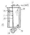
以下、本発明の実施の形態となるタービンブレードの加工装置M0,200において、各実施形態の詳細構成を説明する。先ず、図11と図12に示すように、タービンブレード1の中央に位置する羽根部1Aを把持する羽根把持具10の第1実施例は、タービンブレード1の羽根部1Aを包囲して把持すべく、筒体11の外周壁11Aにはタービンブレード1の羽根部1Aに突き当てる位置決めピンP1,P2,・・・が筒内に突出している。これで筒体内に挿入されたタービンブレード1の羽根部1Aを位置決めピンP1,P2,・・・で仮止めし、筒体の下側となる片側開口を閉塞した状態で固定した後、この筒体11の内部空間に液体(水・水道水・純水)W1を充填し、これを凝固材として氷結させる凝固部(凝固システム)400を外部に配置している。また、上記液体(水・水道水・純水)W1に替えて、石膏やパラフィン等の蝋顆粒・硬化性樹脂顆粒W2を充填して溶融液体WOとし、これを凝固材として固着させる凝固部(凝固システム)500を外部に配置している。上記凝固部(凝固システム)400は図16に示し、上記凝固部(凝固システム)500は図18に示す。Hereinafter, the detailed configuration of each embodiment will be described in the turbine blade machining apparatus M0, 200 according to the embodiment of the present invention. First, as shown in FIGS. 11 and 12, the first embodiment of the
また、羽根把持具10の別の第2実施例は、図13と図14に示すように、タービンブレード1の中央に位置する羽根部1Aを把持する羽根把持具10は、タービンブレード1の羽根部1Aを包囲して把持すべく、軸心方向Oに二つ割りの筒体11(筒片11A、副筒片11B)と、この筒体11(筒片11A、副筒片11B)の左右筒端には、各々突縁a,a´と凹縁b,b´とを設けタービンブレード1の羽根部1Aの両端における凹凸の外周面形状に合わせられ、筒部の軸心方向に対して直交方向Xに羽根部1Aの両端外周面の凹凸を受け止める。また、上記筒片11A、副筒片11Bの外壁には筒内空間に突出させた複数本の位置決めピンP1,P2,・・・が固着されており、上記筒片11A、副筒片11Bを接合ボルトV1,V2・・・で結合することで、羽根部1Aの凸面と凹面とを当接支持する。通常は、この状態でブレード1の羽根部1Aが羽根把持具10により把持された形態となり、ルート部1Bとシュラウド部1Cとを前後して同時多軸制御された加工ヘッドKH1により加工される。この実施例では、ブレード1の羽根部を位置決めピンP1,P2,・・・で固定した後、この筒体11の内部空間に液体(水・水道水・純水)W1、又は、石膏やパラフィン等の蝋顆粒・硬化性樹脂顆粒W2を充填して溶融液体WOとし、これを凝固材として固着させる凝固部(凝固システム)400を外部に配置している。上記凝固部(凝固システム)400は、液体(水・水道水・純水)W1を低温で凍結させる冷凍ユニット110を主要構成とするものと、図18に 示すように、石膏やパラフィン等の蝋顆粒・硬化性樹脂顆粒W2を加温ユニット120で溶融する凝固部(凝固システム)500とからなる。Further, as shown in FIGS. 13 and 14, another second embodiment of the
上記冷凍ユニット110とこれによる液体(水)の充填・凝固工程は、図15と図16に示す。先ず、冷凍ユニット110は、冷凍機Aと冷凍容器Bと冷凍温度制御部Cと冷凍エレメントDとからなり、この冷凍容器B内に入れられた羽根把持具10内の水W1を凝固させる機能を持っている。上記冷凍ユニット110による液体(水)の充填・凝固工程と加工工程を説明する。先ず、タービンブレード取付工程(1)にて、羽根把持具10における二つ割り筒体11でタービンブレード1の中央に位置する羽根部1Aを把持する。続いて、充填工程(2)で筒体11内に液体(水)W1を注入する。上記羽根把持具10を冷凍ユニット110内に入れて液体(水)W1の凝固(氷結)工程(3)を行う。氷結した羽根把持具10を冷凍ユニット110から取り出し、マシニングセンタ及び研削盤を兼用したCNC制御装置により運転され、エンドミル・研磨する機能を持つ多軸制御工作機械MOの加工ヘッドKH1により、ルート部1Bとシュラウド部1Cとを前後して便ブレード両端部の加工工程(4)が行われる。最後に、羽根把持具10を多軸制御工作機械MOの冶具Gからのタービンブレードの取り外し工程(5)により、取り外し、氷結を自然界解凍させるか、強制加熱して急速に解凍して加工を終了させる。 The refrigeration unit 110 and the liquid (water) filling / coagulation process using the refrigeration unit 110 are shown in FIGS. First, the refrigeration unit 110 includes a refrigerator A, a refrigeration container B, a refrigeration temperature control unit C, and a refrigeration element D, and has a function of solidifying water W1 in the
上記羽根把持具10の凝固部(凝固システム)400において、タービンブレード1の羽根部1Aを石膏やパラフィン等の蝋顆粒・硬化性樹脂顆粒W2を加温ユニット120による溶融する凝固部(凝固システム)500は、図18に説明する。蝋顆粒・硬化性樹脂顆粒・蝋・パラフィンを加温して溶融させ、常温に降温させて凝固させる加温ユニット120は、加熱機Eと加熱容器Fと加熱温度制御部Gと加熱エレメントHとからなり、この加熱容器F内に入れられた羽根把持具10内の蝋・パラフィンを溶解させる機能を持っている。蝋・パラフィンを溶解させられた羽根把持具10は、大気中に放置することで、温度が低下して凝固体とする凝固部(凝固システム)500とからなる。In the coagulation part (coagulation system) 400 of the
上記加温ユニット120による蝋顆粒・硬化性樹脂顆粒・蝋・パラフィンの充填・凝固工程と加工工程を図17で説明する。先ず、タービンブレード取付工程(1)にて、羽根把持具10における二つ割り筒体11でタービンブレード1の中央に位置する羽根部1Aを把持する。続いて、蝋顆粒・硬化性樹脂顆粒の充填工程(2´)で筒体11内に素材を注入する。上記羽根把持具10を加温ユニット120内に入れて溶解させる溶融工程(3´)を行う。溶融した羽根把持具10を加温ユニット120から取り出し、液体の凝固工程(4´)を行い、羽根把持具10に羽根部1Aを強固に固定する。上記羽根把持具10をマシニングセンタ及び研削盤を兼用した冶具に取り付けCNC制御装置により運転され、エンドミル・研磨する機能を持つ多軸制御工作機械MOの加工ヘッドKH1により、ルート部1Bとシュラウド部1Cとを前後してタービンブレード両端部の加工工程(5´)が行われる。加工後は、多軸制御工作機械MOの冶具から羽根把持具10を取り外し、再溶融工程(6´)により溶解する。最後に、羽根把持具10を分解してタービンブレードの取り外し工程(7´)加工を終了させる。The wax granule, curable resin granule, wax and paraffin filling / coagulation step and processing step by the
本発明のタービンブレードの加工装置M0,200における第3の実施例は、上記両端把持具30,40において、先ず、上記図10に示すように、ブレ止め機能を排除した両端把持具30,40を図19(a)(b)に示す。両端把持具30は、継手Jで繋がれた二つ割りの筒体30a,30b内にルート部1Bの表側と裏側の凸形状に係合する凹部O1と凹部O2が形成されており、この空間の凹部O1と凹部O2にルート部1Bの表側と裏側とを嵌め合いボルトV1で型枠として固着されている。また、両端持具40も同様に、図10に示すように、継手Jで繋がれた二つ割りの筒体40a,40b内にシュラウド部1Cの表側と裏側の凸形状に係合する凹部O1と凹部O2が形成されており、この空間の凹部O1と凹部O2にシュラウド部1Cの表側と裏側とを嵌め合いボルトV2で型枠として固着される。 Third embodiment in the processing device M0, 200 of the turbine blade of the present invention, in the two ends gripper 30 and 40, first, as shown in FIG 10, both end gripper to eliminate the shake prevention function 30,40 Are shown in FIGS. 19 (a) and 19 (b). The both-end gripping tool 30 is formed with recesses O1 and O2 that engage with the convex shapes on the front side and the back side of the root portion 1B in the split cylinders 30a and 30b connected by the joint J. The front side and the back side of the root part 1B are fitted to O1 and the concave part O2, and are fixed as a mold frame with a bolt V1. Similarly, as shown in FIG. 10, the both-end holding tool 40 is also provided with a concave portion O1 and a concave portion that engage with the convex shapes on the front side and the back side of the shroud portion 1C in the split cylinders 40a and 40b connected by the joint J. O2 is formed, and the front side and the back side of the shroud portion 1C are fitted into the concave portion O1 and the concave portion O2 of this space and fixed as a mold frame with the bolt V2.
上記両端把持具30,40により、タービンブレードのルート部1Bとシュラウド部1Cとを包囲して把持するタービンブレードの加工装置200を構成している。これにより、両端把持具30,40は、図7に示すように、CNC制御装置300の同時多軸制御のもとに加工ヘッドKH2と左右に配置した旋回チャックSC1,SC2により両持ちに把持され、旋回チャックSC1,SC2の旋回制御と、同時多軸制御された加工ヘッドKH2とにより、三次元形状の羽根部1AがエンドミルEM・バフBF・ベルト研磨BKを交換して加工される。更に、上記加工ヘッドKH2は、タービンブレード1の中央に位置する羽根部1Aを変質温度以下で加工すべく、タービンブレード材1の加工温度をサーモブラフィで温度検出する温度検出部60とその温度制御部70とを備えている。 The both-end gripping tools 30 and 40 constitute a turbine blade machining apparatus 200 that surrounds and grips the root portion 1B and shroud portion 1C of the turbine blade. As a result, as shown in FIG. 7, the both-end gripping tools 30 and 40 are gripped by both ends by the machining head KH2 and the swiveling chucks SC1 and SC2 arranged on the left and right under the simultaneous multi-axis control of the CNC control device 300. The three-dimensional blade portion 1A is processed by exchanging the end mill EM, the buff BF, and the belt polishing BK by the swing control of the swing chucks SC1 and SC2 and the machining head KH2 that is simultaneously multi-axis controlled. Further, the processing head KH2 includes a temperature detection unit 60 for detecting the processing temperature of the
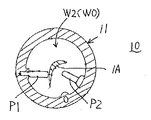
更に、本発明のタービンブレードの加工装置M0,200における第4の実施例は、図20〜図22に示すように、上記羽根把持具10や両端把持具30,40において、筒体13内に挿入し複数本の位置決めピンP1,P2,・・・で固持された羽根部1Aの空間に鋼球・砂・ビーズ(大・中・小・軟・硬の混合物)等の球状材W4を充填させ、この球状材W4に油圧手段OP等で外圧を加圧させることで起きる球状材W4間の引き締め作用により、各球状材W4間が強く結合し合い自由に移動できなくなり加圧固持させられるものである。勿論、図21に示すように、筒体13内に挿入する複数本の位置決めピンP1,P2,・・・を省略し、空間に鋼球・砂・ビーズ(大・中・小・軟・硬の混合物)等の球状材W4のみを充填させ、この球状材W4に油圧手段OP等で外圧を加圧させることで起きる球状材W4間の引き締め作用による実施でも良い。Furthermore, the fourth embodiment of the turbine blade machining apparatus M0, 200 according to the present invention includes, as shown in FIG. 20 to FIG. Filled with a spherical material W4 such as steel balls, sand, beads (mixture of large, medium, small, soft, and hard) in the space of the blade 1A inserted and held by a plurality of positioning pins P1, P2,. The spherical material W4 is tightly coupled with each other by the tightening action between the spherical materials W4 caused by pressurizing external pressure to the spherical material W4 by the hydraulic means OP or the like, so that the spherical materials W4 cannot be moved freely and are held under pressure. It is. Of course, as shown in FIG. 21 , a plurality of positioning pins P1, P2,... Inserted into the
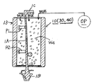
更に、本発明のタービンブレードの加工装置M0,200における第5の実施例は、図23に示すように、上記羽根把持具10や両端把持具30,40において、位置決めピンを省略し、筒体13´内の空間に被把持材として砂材(大・中・小・球・角片の混合物)W5を充填するとともに、水道水等の液体W1を配管Pから筒体内に注入することで、各砂材W5間が強く結合し合い自由に移動できなくなり強固に凝固させる実施でも良い。Furthermore, in the fifth embodiment of the turbine blade machining apparatus M0, 200 of the present invention, as shown in FIG. 23, the
本発明のタービンブレードの加工装置M0,200は、上記のように各種の実施例からなり、何れの加工装置M0,200を使用することも可能である。タービンブレードの形状や大きさ等に応じた加工装置M0,200の最良の組み合わせにより、高精度加工と加工効率が高められる。The turbine blade machining apparatus M0, 200 according to the present invention includes various embodiments as described above, and any of the machining apparatuses M0, 200 can be used. High-precision machining and machining efficiency can be improved by the best combination of machining devices M0 and 200 according to the shape and size of the turbine blade.
本発明の実施形態となるタービンブレードの加工方法によれば、下記の効果が奏せられる。特に、タービンブレードのルート部やシュラウド部の他、特に、上記羽根部の加工は、同時五軸制御のもとにエンドミル・バフ・研磨により、荒加工・中仕上げ・精密仕上げが材質変化を起こす約630℃の変質温度以下で連続して加工され焼け現象が完全に防止できる。その上、加工が効率的に実施できる。更に、上記羽根部の加工は、同時五軸制御のもとにエンドミル・バフ・研磨の各加工が、手仕上げの動きをモーションキャプチャーティーチングによるフィードバックで材質変化を起こすことなく連続して品質の良い自動加工できる。 The turbine blade machining method according to the embodiment of the present invention has the following effects. In particular, in addition to the root part and shroud part of the turbine blade, the above blade part is processed by end milling, buffing and polishing under simultaneous five-axis control, resulting in material changes in roughing, intermediate finishing and precision finishing. It is continuously processed at a temperature of about 630 ° C. or lower, and the burning phenomenon can be completely prevented. In addition, processing can be performed efficiently. In addition, the processing of the blades described above is a continuous five-axis control with end milling, buffing, and polishing. Can be processed automatically.
また、実施形態となるタービンブレードの加工装置によれば、下記の効果が奏せられる。特に、タービンブレードのルート部やシュラウド部の他、特に、上記羽根部の加工は、同時多軸制御のもとにエンドミル・バフ・研磨により、荒加工・中仕上げ・精密仕上げが材質変化を起こす約630℃の変質温度以下で連続して加工され焼け現象を完全に防止させた加工を実施させることができる。その上、加工を効率的に実施できる。更に、上記羽根部の加工は、同時多軸制御のもとにエンドミル・バフ・研磨の各加工が、手仕上げの動きをモーションキャプチャーティーチングによるフィードバックで材質変化を起こすことなく連続して品質の良い自動加工を実施させることができる。 Further, according to the turbine blade machining apparatus of the embodiment, the following effects can be obtained. In particular, in addition to the root part and shroud part of the turbine blade, the above blade part is processed by end milling, buffing and polishing under simultaneous multi-axis control, resulting in material changes in roughing, intermediate finishing and precision finishing. It is possible to perform processing that is continuously processed at a temperature of about 630 ° C. or less and that completely prevents the burning phenomenon. In addition, processing can be performed efficiently. Furthermore, the processing of the blades described above is based on simultaneous multi-axis control. End milling, buffing, and polishing are performed continuously without any material change by feedback of motion capture teaching of hand finishing movements. Automatic processing can be performed.
更に、タービンブレードの加工装置によれば、下記の効果が奏せられる。加工済みのルート部及びシュラウド部に対しては、嵌り合う凹状の型枠で確実に固着できる。また、タービンブレードの羽根部は、位置決めピンと氷結又は石膏又はパラフィン等の固化材で確実に固着できる。そして、筒体内に挿入した羽根部とルート部又はシュラウド部とは、鋼球・砂等の球状材で加圧させることで確実に固持できる。更には、筒体内に挿入した被把持材として砂材を充填するとともに、水等の液体を注入して強固に凝固できる。しかも、何れの加工装置も、被把持材を筒体内から外す操作が簡潔・迅速にできる。Furthermore, according to the processing apparatus of a turbine blade, the following effects are produced. The processed root portion and shroud portion can be securely fixed by the fitting concave mold. Further, the blade portion of the turbine blade can be securely fixed to the positioning pin with solidification material such as freezing, gypsum, or paraffin. And the blade | wing part inserted in the cylinder, a root | route part, or a shroud part can be firmly fixed by making it press with spherical materials, such as a steel ball and sand. Furthermore, it can be solidified firmly by filling a sand material as a material to be grasped inserted into the cylinder and injecting a liquid such as water. In addition, in any of the processing apparatuses , the operation of removing the gripped material from the cylinder can be performed simply and quickly.
尚、本発明のタービンブレードの加工方法及び加工装置M0,200は、上記各実施の形態における構成に限定されず、その発明の要旨内での設計変更が自由にできる。例えば、タービンブレードの加工方法における各加工工程とか把持工程の変更、タービンブレードの加工装置における把持具や加工ヘッドの制御軸数や加工ヘッドの方式の変更、その他の装置における若干の変更、把持具における各方式の使用部材や被把持材・球状材・砂材等の変更も自由にできる。この変更によっても上記タービンブレードの加工方法及び加工装置と同様な作用が得られる。その他の詳細構成の設計変更も可能である。The turbine blade processing method and the processing apparatuses M0 and 200 of the present invention are not limited to the configurations in the above embodiments, and can be freely changed in design within the scope of the invention. For example, changes in each machining process or gripping process in the turbine blade machining method, changes in the number of gripping tools and machining head control axes and machining head methods in the turbine blade machining apparatus, slight changes in other equipment, gripping tools It is also possible to freely change the members used in each method, the gripped material, the spherical material, the sand material, and the like. This change also provides the same effects as those of the turbine blade machining method and machine. Other detailed configuration design changes are also possible.
本発明は、その対象物を航空機のジェットエンジンや発電機用のタービンに使用されるタービンブレードやターボチャージャーのブレード等の実施例で説明したものであるが、様々な製品装置のブレードとしての適用が可能である。 The present invention has been described with reference to embodiments of the turbine blade and turbocharger blade used in aircraft jet engines and generator turbines. Is possible.
1 タービンブレード
1A 羽根部
1B ルート部
1C シュラウド部
10 羽根把持具
11 筒体
11A 筒片
11B 副筒片
13,13´筒体
20 両端加工部
30,40 両端把持具
30a,30b 筒体
40a,40b 筒体
50 羽根加工部
60 温度検出部
70 温度制御部
(1)タービンブレード取付工程
(2)充填工程
(3)液体の凝固(氷結)工程
(4)加工工程
(5)タービンブレードの取り外し工程
(2´)蝋顆粒・硬化性樹脂顆粒の充填工程
(3´)溶融工程
(4´)液体の凝固工程
(5´)タービンブブレード両端部の加工工程
(6´)再溶融工程
(7´)タービンブレードの取り外し工程
(A)羽根把持工程
(B)両端加工工程
(B1)シュラウド加工工程
(B2)ルート加工工程
(C)両端把持工程
(D)羽根加工工程
A 冷凍機
B 冷凍容器
BF バフ
BK ベルト研磨
C 冷凍温度制御部
C1,C2 旋回チャック
CM カメラ
EM エンドミル
E 加熱機
F 加熱容器
G 加熱温度制御部
H 加熱エレメント
J 継手
KH1 加工ヘッド
KH2 加工ヘッド
KMO 研磨機
M 熟練工
MO タービンブレードの加工装置
O1 凹部
O2 凹部
OP 油圧手段
P 配管
P1,P2 位置決めピン
SCO 中央旋回チャック
TK 砥石研磨
V1,V2 ボルト
W1 液体(水・水道水・純水)
W2 石膏やパラフィン等の蝋顆粒・硬化性樹脂顆粒
W4 球状材
W5 砂材(大・中・小・球・角片の混合物)
WO 溶融液体
100 多軸制御工作機械
110 冷凍ユニット
120 加温ユニット
200 タービンブレードの加工装置
300 CNC制御装置
330 モーションキャプチャー制御部
400 凝固部(凝固システム)
500 凝固部(凝固システム)DESCRIPTION OF
A refrigerator
B Freezing container BF Buff BK Belt polishing
C Refrigeration temperature control unit C1, C2 Swivel chuck CM Camera EM End mill E Heater F Heating container G Heating temperature control unit H Heating element J Joint KH1 Processing head KH2 Processing head KMO Polishing machine M Processing unit O1 Recessed O2 Recessed O2 Concave OP Hydraulic means P Piping P1, P2 Positioning pin SCO Central turning chuck TK Grinding wheel V1, V2 Bolt W1 Liquid (water, tap water, pure water)
W2 Wax granules such as gypsum and paraffin, curable resin granules W4 Spherical material W5 Sand material (mixture of large, medium, small, sphere and square pieces)
WO Molten liquid 100 Multi-axis control machine tool 110
500 Solidification part (coagulation system)
Claims (5)
上記ルート部とシュラウド部とを加工する両端加工工程及び羽根部を加工する羽根加工工程は、同時多軸制御のもとに加工し、
上記羽根部を加工する羽根加工工程は、同時多軸制御のもとにエンドミル・バフ・研磨からなり、手仕上げの動きをモーションキャプチャーティーチングにより自動加工することを特徴とするタービンブレードの加工方法。A blade gripping step for gripping a blade portion located at the center of the turbine blade, a both-end processing step for processing the exposed root portion and the shroud portion of the turbine blade simultaneously or back and forth, and the turbine blade from the blade gripper both ends gripping step of gripping the machined root portion and the shroud portion removed, and the blade processing step of processing the blade portion below alteration temperature at the center of the turbine blades, in the processing method of a turbine blade made from
The both-end machining process for machining the root part and the shroud part and the blade machining process for machining the blade part are processed under simultaneous multi-axis control,
The blade processing step for processing the blade portion includes end milling, buffing, and polishing under simultaneous multi-axis control, and automatically processing a hand-finishing motion by motion capture teaching .
上記両端加工部は、同時多軸制御のもとにエンドミル及び研削加工する主軸ヘッドと、タービンブレード材の加工温度を検出する温度検出部とその温度制御部とを備え、
上記主軸ヘッドは、手仕上げの動きをモーションキャプチャーティーチングにより自動加工制御するモーションキャプチャー制御部を備え、
上記羽根加工部は、同時多軸制御のもとにエンドミル・バフ・研磨からなる主軸ヘッドと、タービンブレード材の加工温度を検出する温度検出部とその運転制御部とを備えたものであることを特徴とするタービンブレードの加工装置。 A blade gripper for gripping a blade portion located in the center of the turbine blade, a both-end processed portion that is gripped by the blade gripper and processes the root portion and the shroud portion simultaneously or before and after, and the root portion of the turbine blade And a blade blade processing unit that grips the shroud portion, and a blade processing unit that processes the blade part located at the center of the turbine blade at a temperature lower than the alteration temperature .
The both-end machining section includes a spindle head that performs end milling and grinding under simultaneous multi-axis control, a temperature detection section that detects a machining temperature of the turbine blade material, and a temperature control section thereof.
The spindle head is equipped with a motion capture control unit that automatically controls hand-finishing motion by motion capture teaching.
The blade machining section is provided with a spindle head composed of end mill, buffing and polishing under simultaneous multi-axis control, a temperature detection section for detecting the machining temperature of the turbine blade material, and its operation control section. Turbine blade processing apparatus characterized by the above.
Priority Applications (1)
| Application Number | Priority Date | Filing Date | Title |
|---|---|---|---|
| JP2009039974A JP4986083B2 (en) | 2009-01-29 | 2009-01-29 | Turbine blade machining method and turbine blade machining apparatus |
Applications Claiming Priority (1)
| Application Number | Priority Date | Filing Date | Title |
|---|---|---|---|
| JP2009039974A JP4986083B2 (en) | 2009-01-29 | 2009-01-29 | Turbine blade machining method and turbine blade machining apparatus |
Publications (3)
| Publication Number | Publication Date |
|---|---|
| JP2010174876A JP2010174876A (en) | 2010-08-12 |
| JP2010174876A5 true JP2010174876A5 (en) | 2012-04-05 |
| JP4986083B2 JP4986083B2 (en) | 2012-07-25 |
Family
ID=42706065
Family Applications (1)
| Application Number | Title | Priority Date | Filing Date |
|---|---|---|---|
| JP2009039974A Expired - Fee Related JP4986083B2 (en) | 2009-01-29 | 2009-01-29 | Turbine blade machining method and turbine blade machining apparatus |
Country Status (1)
| Country | Link |
|---|---|
| JP (1) | JP4986083B2 (en) |
Families Citing this family (8)
| Publication number | Priority date | Publication date | Assignee | Title |
|---|---|---|---|---|
| JP5470605B2 (en) * | 2009-09-30 | 2014-04-16 | 株式会社ナサダ | Resin filled solidification method of blade, resin filled solidification method of blade, resin filled solidification processing device of long blade, resin filled solidification method of long blade |
| JP5916510B2 (en) * | 2012-05-16 | 2016-05-11 | 三菱重工業株式会社 | Manufacturing method of blade for rotary machine and balance weight casting jig used therefor |
| CN103028917B (en) * | 2012-12-31 | 2014-12-03 | 四川绵竹鑫坤机械制造有限责任公司 | Machining process for low-pressure first-stage stationary blades of gas turbines |
| CN103111812B (en) * | 2013-03-14 | 2016-01-06 | 北重阿尔斯通(北京)电气装备有限公司 | The processing method of steam turbine axial blade |
| CN105252058A (en) * | 2015-11-20 | 2016-01-20 | 湖北双剑鼓风机股份有限公司 | Five-shaft milling processing method of turbine impeller |
| CN107838642B (en) * | 2017-12-18 | 2019-03-05 | 中国航发贵州黎阳航空动力有限公司 | A kind of processing method of bipode thin wall vane part |
| JP2019124183A (en) * | 2018-01-17 | 2019-07-25 | 徐光善 | Process of manufacture of firtree type turbine blade |
| CN114248078B (en) * | 2021-12-09 | 2023-04-25 | 四川绵竹鑫坤机械制造有限责任公司 | Processing method of titanium alloy blade |
Family Cites Families (6)
| Publication number | Priority date | Publication date | Assignee | Title |
|---|---|---|---|---|
| JPH09155503A (en) * | 1995-12-05 | 1997-06-17 | Hitachi Ltd | Mold for precision casting and method thereof |
| JPH11829A (en) * | 1997-06-06 | 1999-01-06 | United Technol Corp <Utc> | Intermediate object for manufacturing part of highly precise form |
| SG80000A1 (en) * | 1997-12-19 | 2001-04-17 | United Technologies Corp | A fixture for use in disposing a region of material on the shroud of a rotor blade |
| JP2002326150A (en) * | 2001-05-01 | 2002-11-12 | Hmy Ltd | Blade surface polishing device and polishing method using the same |
| JP2004098207A (en) * | 2002-09-09 | 2004-04-02 | Mitsubishi Heavy Ind Ltd | Ceramic coating polishing method and turbine blade manufacturing method for gas turbines |
| JP2005074568A (en) * | 2003-09-01 | 2005-03-24 | Mitsubishi Heavy Ind Ltd | Multiple spindle machine and workpiece machining method |
-
2009
- 2009-01-29 JP JP2009039974A patent/JP4986083B2/en not_active Expired - Fee Related
Similar Documents
| Publication | Publication Date | Title |
|---|---|---|
| JP4986083B2 (en) | Turbine blade machining method and turbine blade machining apparatus | |
| JP2010174876A5 (en) | ||
| JP2005515907A (en) | Method and apparatus for processing blanks entirely with a processing machine or milling machine | |
| CN102658458B (en) | Manufacturing method of pedestal bearing for turbocharger and positioning tool for same | |
| WO2010073823A1 (en) | Machine tool | |
| KR102355786B1 (en) | Deburring automation system | |
| TWI436856B (en) | Composite chamfering device for ingot | |
| JP3172627U (en) | Turbine blade both-end gripping device | |
| WO2021037107A1 (en) | Valve element synchronous grinding and deburring integrated method based on overlap value detection, and system | |
| JP4741188B2 (en) | Method and apparatus for processing a blank entirely | |
| CN110625943A (en) | Supplementary processing agency of part based on six compound uninterrupted 3D printers | |
| CN102922397A (en) | Accessory lathe-grinding integration device for lathe machining center and use method thereof | |
| CN108443450B (en) | Production method of rotor for hydraulic coupler | |
| JP2004283867A (en) | Method and device for finishing casting | |
| CN206085066U (en) | Planer joint manipulator | |
| CN201483405U (en) | Universal parallel clamping apparatus | |
| KR20080055694A (en) | Casting finishing device | |
| CN100526012C (en) | Grinding polishing machine | |
| CN202964111U (en) | Quick machining device for hemispheric shell end surface | |
| CN112706016B (en) | Grinding treatment method and server suitable for engine crankshaft | |
| CN214559679U (en) | Single-bent glass bridge deck profiling process machining device | |
| CN103273288A (en) | Blade precision mould processing method | |
| CN211760607U (en) | Radial angle adjusting device of tool grinder main shaft for rotary file processing | |
| AU2006202154B2 (en) | A method and system for producing a cast object | |
| JP2005040921A (en) | Tool having copying guide member, deburring machine using the tool, and deburring method using the same |