JP2010174870A5 - - Google Patents
Download PDFInfo
- Publication number
- JP2010174870A5 JP2010174870A5 JP2009022002A JP2009022002A JP2010174870A5 JP 2010174870 A5 JP2010174870 A5 JP 2010174870A5 JP 2009022002 A JP2009022002 A JP 2009022002A JP 2009022002 A JP2009022002 A JP 2009022002A JP 2010174870 A5 JP2010174870 A5 JP 2010174870A5
- Authority
- JP
- Japan
- Prior art keywords
- diaphragm
- cylindrical portion
- valve
- gas passage
- lpg fuel
- Prior art date
- Legal status (The legal status is an assumption and is not a legal conclusion. Google has not performed a legal analysis and makes no representation as to the accuracy of the status listed.)
- Granted
Links
Images


Description
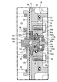
また前記ガス通路溝42は、そのガス通路溝42の相互に対向する一対の側壁すなわち中央円筒部17bの外壁および中間円筒部17cの内壁間の間隔が前記ガス通路カバー18側に向かうにつれて大きくなるように傾斜させて前記ボディ17に設けられるものであり、LPG燃料用減圧弁は、図1で示すように、弁機構15の軸線を水平とした姿勢で車両に搭載される。
Further, the
ところで前記ガス通路カバー18は、前記ボディ17の外周リング部17aの一面との間に環状のシール部材45を介在せしめるリング状の外周平板部18aと、前記外周リング部17aに嵌合されるようにして一端部が外周平板部18aの内周縁に連なる外側円筒部18bと、前記ボディ17の第1環状連結板部17dに近接対向するようにして外側円筒部18bの他端に外周が連なるリング状の中間平板部18cと、該中間平板部18cの内周に一端を連ならせるとともに前記ボディ17における中央円筒部17bの一端を嵌入せしめる内側円筒部18dと、前記中央円筒部17bの一端に間隔をあけて対向するようにして前記内側円筒部18dの他端に連なる円板状の中央平板部18eとを一体に有する。
By the way, the
前記ガス通路カバー18の中央平板部18eおよび前記ボディ17の中央円筒部17b間には、前記弁孔24に通じる減圧室48が形成されており、この減圧室48を前記ガス通路43に通じさせるための連通路49を、ガス通路カバー18および前記中央円筒部17b間に形成するための切欠き50が、前記中央円筒部17bの一端部外周に設けられる。すなわち前記ガス通路43の始点PSは、前記連通路49のガス通路43への開口端である。
A
第1リテーナ83は、ダイヤフラムロッド85に一体に設けられる。このダイヤフラムロッド85は、一端を閉じるとともに弁機構15側の他端を開放した形状の有底円筒部85aと、該有底円筒部85aの一端閉塞部から半径方向外方に張り出す前記第1リテーナ83と、前記有底円筒部85aの一端閉塞部中央に同軸に連なる軸部85bとを一体に有するものであり、有底円筒部85aよりも小径である前記軸部85bは、ダイヤフラム16の中央部に設けられる中心孔87に挿通される。
The
しかも第1の加熱手段60が、前記弁室30を囲むようにして前記弁ハウジング21に設けられる加熱流体通路61を加熱流体であるエンジン冷却水が流通するように構成されて成るので、横断面円形である弁室30の内周壁面を効果的に加熱して、弁室30内でのガスへの伝熱効率をより高めることができる。また前記加熱流体通路61は、弁座25と反対側から前記弁室30を囲む部分を有して弁ハウジング21に設けられるので、弁室30内でのLPG燃料への伝熱効率をより一層高めることができる。
Moreover the first heating means 60, the engine cooling water heated fluid passage 6 1 so as to surround the
弁ハウジング21内に形成されるガス通路43は、弁ハウジング21のボディ17に設けられる複数のフィン40…,41…で迷路状に屈曲されるのであるが、ガス通路43の一部を構成するようにして相互に対向する2つの壁面すなわちボディ17における中央円筒部17bの外面および中間円筒部17cの内面には、ガス通路43の始点PSから終点PEまでのLPG燃料の主流れ方向44に対して上流側に指向するように傾斜しつつ前記主流れ方向44に交互に配置されるようにして複数ずつのフィン40…,41…が一体に突設されるので、ガス通路43を迷路状に屈曲させるフィン40…,41…の長さを長くして各フィン40…,41…の放熱面積を広くすることが可能となるとともに、ガス通路43内でのLPG燃料の流通経路を長くすることが可能となり、LPG燃料への伝熱効率をより高めることができる。しかも各フィン40…,41…が、ガス通路43の始点PSから終点PEまでのLPG燃料の主流れ方向44に対して上流側に指向するものであるので、LPG燃料のうち比重の高い液体成分が各フィン40…,41…の基端部で捕捉され易くなり、液体成分を優先的に加熱してLPG燃料が気液混合状態となるのを抑制することができる。
The
また弁機構15の弁軸部34bに連結されるダイヤフラム16の外周縁は、弁ハウジング21とは別部材であるダイヤフラムフランジ77と、該ダイヤフラムフランジ77の外周に結合されるダイヤフラムカバー78とで挟持されるものであり、弁機構15の軸線方向で電気ヒータ68がダイヤフラムフランジ77および弁ハウジング21間に配置されるので、ダイヤフラム16の受圧面積を、LPG燃料の流量変化に対する制御圧の変化を少なくして調圧性能を高めるために大きくすると、弁ハウジング21およびダイヤフラムフランジ77間に電気ヒータ68が前記ダイヤフラムフランジ77と重なるように配置される構成となるのであるが、ダイヤフラムフランジ77を弁ハウジング21とは別部材とすることにより、電気ヒータ68の弁ハウジング21への取付けが容易となる。
The outer peripheral edge of the
したがって減圧弁の組立時の制約が少なく、設計自由度を増大して生産性を高めることができる。すなわちダイヤフラム16およびダイヤフラムロッド85を弁軸部34bとは無関係に連結するようにして作業性を高め、ダイヤフラム16の周縁部をダイヤフラムカバー78およびダイヤフラムフランジ77間に挟持する作業もスペース的な制約がない状態で行うことを可能としてボディ17側に工具配置のための無駄なスペースを確保することを不要として減圧弁の小型化を図ることができる。またボディ集合体100側で弁機構15の気密検査を行い、ダイヤフラム集合体96側でダイヤフラム16の気密検査を行うようにしてボディ集合体100およびダイヤフラム集合体96でそれぞれ個別に機能検査を行うことが可能であり、信頼性を高めることができ、各部の組付け状態の確認が容易となる。さらにダイヤフラム集合体96におけるばね81,82のばね定数を異ならせたり、ダイヤフラム16の面積を異ならせたりして、複数種類のダイヤフラム集合体96を準備しておくことにより、ボディ集合体100を共通としながら制御圧の異なる複数種類の減圧弁を製造することができる。
Therefore, there are few restrictions at the time of the assembly of a pressure-reducing valve, design freedom can be increased, and productivity can be improved. That is, the workability is improved by connecting the
Priority Applications (1)
| Application Number | Priority Date | Filing Date | Title |
|---|---|---|---|
| JP2009022002A JP5243289B2 (en) | 2009-02-02 | 2009-02-02 | LPG fuel heating device |
Applications Claiming Priority (1)
| Application Number | Priority Date | Filing Date | Title |
|---|---|---|---|
| JP2009022002A JP5243289B2 (en) | 2009-02-02 | 2009-02-02 | LPG fuel heating device |
Publications (3)
| Publication Number | Publication Date |
|---|---|
| JP2010174870A JP2010174870A (en) | 2010-08-12 |
| JP2010174870A5 true JP2010174870A5 (en) | 2011-11-24 |
| JP5243289B2 JP5243289B2 (en) | 2013-07-24 |
Family
ID=42706061
Family Applications (1)
| Application Number | Title | Priority Date | Filing Date |
|---|---|---|---|
| JP2009022002A Expired - Fee Related JP5243289B2 (en) | 2009-02-02 | 2009-02-02 | LPG fuel heating device |
Country Status (1)
| Country | Link |
|---|---|
| JP (1) | JP5243289B2 (en) |
Families Citing this family (1)
| Publication number | Priority date | Publication date | Assignee | Title |
|---|---|---|---|---|
| JP5875062B2 (en) | 2011-11-01 | 2016-03-02 | 株式会社ケーヒン | Pressure reducing valve for LPG fuel |
Family Cites Families (7)
| Publication number | Priority date | Publication date | Assignee | Title |
|---|---|---|---|---|
| JPS52140813A (en) * | 1976-05-19 | 1977-11-24 | Hitachi Ltd | Motor |
| JPS58151340U (en) * | 1982-04-05 | 1983-10-11 | 愛三工業株式会社 | LPG engine fuel regulator |
| JP3225176B2 (en) * | 1995-05-01 | 2001-11-05 | 愛三工業株式会社 | LPG fuel heating device |
| JP2000018042A (en) * | 1998-07-03 | 2000-01-18 | Shuichi Kitamura | Scavenging passage for two cycle engine |
| JP4378698B2 (en) * | 2004-05-12 | 2009-12-09 | 株式会社ニッキ | Regulator for LPG |
| JP2005325690A (en) * | 2004-05-12 | 2005-11-24 | Nikki Co Ltd | Regulator for lpg |
| JP4732973B2 (en) * | 2006-07-14 | 2011-07-27 | 株式会社ニッキ | Gas fuel engine vaporizer |
-
2009
- 2009-02-02 JP JP2009022002A patent/JP5243289B2/en not_active Expired - Fee Related
Similar Documents
| Publication | Publication Date | Title |
|---|---|---|
| JP2010176643A5 (en) | ||
| JP2010198587A5 (en) | ||
| JP5162486B2 (en) | Pressure reducing valve | |
| JP6425974B2 (en) | PCV valve mounting structure | |
| JP5394122B2 (en) | Pressure reducing valve | |
| JP2010174870A5 (en) | ||
| JP5982354B2 (en) | Fluid control valve | |
| JP6310453B2 (en) | Tube heat exchanger | |
| JP2010175067A5 (en) | ||
| JP2008202624A (en) | Check valve | |
| JP5875062B2 (en) | Pressure reducing valve for LPG fuel | |
| RU2013139935A (en) | VALVE | |
| JP6195928B2 (en) | Piston for internal combustion engine | |
| JP5243289B2 (en) | LPG fuel heating device | |
| JP5135247B2 (en) | Pressure reducing valve assembly method and pressure reducing valve | |
| JP2010174869A (en) | Lpg fuel heating device | |
| JP5606760B2 (en) | Gas heating equipment | |
| WO2014188623A1 (en) | Tube heat exchanger | |
| JP2013221543A (en) | Check valve | |
| CN102288063A (en) | Vehicle warm air water tank with movable inflow and outflow pipe | |
| JP5722164B2 (en) | Decompressor | |
| JP2011149447A (en) | Valve structure for shock absorber | |
| JP2011202609A (en) | Gas heating device | |
| JP2010174871A (en) | Pressure reducing valve for lpg fuel | |
| JP2010176644A (en) | Gas pressure reducing valve |