JP2010167006A - Cabinet - Google Patents

Cabinet Download PDF

Info

Publication number
JP2010167006A
JP2010167006A JP2009010745A JP2009010745A JP2010167006A JP 2010167006 A JP2010167006 A JP 2010167006A JP 2009010745 A JP2009010745 A JP 2009010745A JP 2009010745 A JP2009010745 A JP 2009010745A JP 2010167006 A JP2010167006 A JP 2010167006A
Authority
JP
Japan
Prior art keywords
drawer
drawers
sliding contact
stage
follower
Prior art date
Legal status (The legal status is an assumption and is not a legal conclusion. Google has not performed a legal analysis and makes no representation as to the accuracy of the status listed.)
Granted
Application number
JP2009010745A
Other languages
Japanese (ja)
Other versions
JP5261209B2 (en
Inventor
Kazuhisa Yokota
一寿 横田
Current Assignee (The listed assignees may be inaccurate. Google has not performed a legal analysis and makes no representation or warranty as to the accuracy of the list.)
Itoki Corp
Original Assignee
Itoki Corp
Priority date (The priority date is an assumption and is not a legal conclusion. Google has not performed a legal analysis and makes no representation as to the accuracy of the date listed.)
Filing date
Publication date
Application filed by Itoki Corp filed Critical Itoki Corp
Priority to JP2009010745A priority Critical patent/JP5261209B2/en
Publication of JP2010167006A publication Critical patent/JP2010167006A/en
Application granted granted Critical
Publication of JP5261209B2 publication Critical patent/JP5261209B2/en
Expired - Fee Related legal-status Critical Current
Anticipated expiration legal-status Critical

Links

Images

Landscapes

  • Drawers Of Furniture (AREA)

Abstract

【課題】家具本体の間口方向の寸法が異なる家具であっても、同一の形状・寸法を有する構成部品からるオールロック機構を提供する。
【解決手段】第1連動部34及び第2連動部は、前記家具本体の天板の下面側に配置され、第1連動部は、錠前31のロック操作時にデッドボルトに押されてZ軸の上方向に移動可能な第1ブロック体38と、X軸方向に沿って移動可能な第2ブロック体40と、Y軸方向に沿って移動可能な第3ブロック体42とを備え、第1ブロック体における第1傾斜摺接部38aと第2ブロック体における第2傾斜摺接部40aとが互いに当接し、且つ第2ブロック体における第3傾斜摺接部40cと第3ブロック体における第4傾斜摺接部42aとが互いに当接することにより、ストッパ体を連結杆46を介してY軸方向に沿って所定量だけ移動させて昇降体の上昇を阻止する。
【選択図】図12
Provided is an all-lock mechanism comprising components having the same shape and dimensions even for furniture having different dimensions in the frontage direction of the furniture body.
A first interlocking portion and a second interlocking portion are disposed on a lower surface side of the top plate of the furniture body, and the first interlocking portion is pushed by a dead bolt when the lock 31 is locked, and the Z-axis A first block body 38 movable in the upward direction, a second block body 40 movable along the X-axis direction, and a third block body 42 movable along the Y-axis direction. The first inclined sliding contact portion 38a in the body and the second inclined sliding contact portion 40a in the second block body are in contact with each other, and the third inclined sliding contact portion 40c in the second block body and the fourth inclination in the third block body When the sliding contact portion 42a comes into contact with each other, the stopper body is moved by a predetermined amount along the Y-axis direction via the connecting rod 46 to prevent the lifting body from rising.
[Selection] Figure 12

Description

本願発明は、前面開放状の家具本体(キャビネット本体)に対して上下多段に配置された全ての抽斗が家具本体に押し込まれた状態で、当該全ての抽斗の引出し動を阻止するオールロック機構を備えたキャビネットなどの什器の構成に関するものである。   The present invention has an all-lock mechanism that prevents all drawers from being pulled out in a state where all the drawers arranged in multiple stages above and below the furniture body (cabinet body) with the front open are pushed into the furniture body. The present invention relates to the structure of fixtures such as cabinets provided.

従来から、キャビネットの転倒するおそれをなくするため、キャビネット本体に上下多段の抽斗を全て閉じた状態から、1つの抽斗を引き出した後に、さらに他の段の抽斗の引出し動を不能にする、いわゆる2重引出し防止装置を利用してオールロックできる装置を備えたもの(特許文献1〜3)が公知である。   Conventionally, in order to eliminate the risk of the cabinet toppling over, after pulling out one drawer from a state in which all the upper and lower multistage drawers are closed to the cabinet body, the drawer movement of the other stage is disabled, so-called The thing (patent documents 1-3) provided with the device which can carry out all lock using a double drawer prevention device is publicly known.

特許公報第3987160号公報(図1〜図6参照)Japanese Patent Publication No. 3987160 (see FIGS. 1 to 6) 特開平10−184151号公報(図1〜図4参照)Japanese Patent Laid-Open No. 10-184151 (see FIGS. 1 to 4) 特開2001−112559号公報(図1〜図9参照)Japanese Patent Laid-Open No. 2001-112559 (see FIGS. 1 to 9)

ところで、特許文献1〜3に示すように、2重引出し防止装置のために垂直方向に昇降可能な縦杆、ロッド及びスライドバーは、キャビネット本体内の側部であって、抽斗の側面と対面する個所に設けられているのが通常である。   By the way, as shown in Patent Documents 1 to 3, the vertical rod, the rod and the slide bar which can be vertically moved for the double drawer preventing device are side portions in the cabinet body and face the side surface of the drawer. It is usually provided at the place to do.

そして、特許文献2の構成では、キー操作による錠前が、キャビネット本体の天版の前面であって、間口方向の中央部に配置され、左右一対の操作杆はそれぞれの中途部にてピン支軸(回動中心)に上下回動可能に支持され、左右一対の操作杆の一端同士が錠前の個所で回動可能に連結され、左右一対の操作杆の各他端は2重引出し防止装置のための縦杆の上端部の係止孔に挿入されて、縦杆を吊支している。左右一対の操作杆の一端における上下対のガイド片の間に上記錠前の偏心部材(デッドボルト)を臨ませる。これにより、錠前に差し込んだキーの回動操作にて偏心部材(デッドボルト)をロック方向に回動させると、左右一対の操作杆の一端側が下向き揺動し、他端が上向き揺動する。これにより、左右両側の縦杆が所定の上昇位置に保持される。そのとき、各縦杆の各抽斗段毎の高さ位置に設けられたロック体の後面に、各抽斗の側面に突出させたストッパ体が当接することで、全ての抽斗の引出し動が阻止される。   And in the structure of patent document 2, the lock by key operation is a front surface of the top plate of a cabinet main body, and is arrange | positioned in the center part of the frontage direction, and a pair of right and left operation rods are pin spindles in each middle part. (The center of rotation) is supported so as to be pivotable up and down, and one end of a pair of left and right operation rods is pivotally connected to each other at the lock, and each other end of the pair of left and right operation rods is a double drawer preventing device. It is inserted in the locking hole of the upper end part of the vertical gutter for suspending the vertical gutter. The eccentric member (dead bolt) of the lock is made to face between the pair of upper and lower guide pieces at one end of the pair of left and right operating rods. Thus, when the eccentric member (dead bolt) is rotated in the locking direction by the rotation operation of the key inserted in the lock, one end side of the pair of left and right operation rods swings downward and the other end swings upward. As a result, the vertical saddles on the left and right sides are held at the predetermined raised positions. At that time, the stopper body protruded from the side surface of each drawer is in contact with the rear surface of the lock body provided at the height position of each drawer stage of each vertical fence, so that all drawers are prevented from being pulled out. The

従って、特許文献2の構成では、錠前の偏心部材の回動量が一定であっても、各操作杆の回動中心からその一端までの距離と、回動中心から他端までの距離とがそれぞれ変わると、当該操作杆の他端の昇降量は変動することになる。そうすると、キャビネット本体の間口方向の寸法が異なると、必然的に操作杆の全長が変更されることになるから、2重引出し防止装置の構成(寸法など)を変更しなければならない。逆に、キャビネット本体の間口方向の寸法が異なっても、2重引出し防止装置の構成(寸法など)を変更しない設計とすると、縦杆のオールロックに必要な上昇量を一定になるように、上記錠前の偏心部材の偏心量を変更したり、操作杆の回動中心位置を変更するなどの各種の設計変更を余儀なくされる結果、キャビネット本体の間口方向の寸法に応じた形状・寸法の部品を準備しなければならず、在庫品数が増加し、その管理が煩雑になるという問題があった。また、左右一対の操作杆の上下揺動時に、操作杆と縦杆の吊支個所との係合部で騒音を発生させるという問題もあった。   Therefore, in the configuration of Patent Document 2, even if the amount of rotation of the eccentric member of the lock is constant, the distance from the rotation center of each operating rod to one end thereof and the distance from the rotation center to the other end are respectively If it changes, the raising / lowering amount of the other end of the operating rod will fluctuate. Then, if the dimensions of the cabinet body in the frontage direction are different, the total length of the operating rod is inevitably changed, so the configuration (dimensions, etc.) of the double drawer preventing device must be changed. Conversely, even if the dimensions of the front of the cabinet body are different, if the design is such that the configuration (dimensions etc.) of the double drawer prevention device is not changed, the amount of lift required for the all lock of the downspout will be constant. As a result of various design changes such as changing the eccentric amount of the eccentric member of the lock and changing the rotation center position of the operating rod, parts with shapes and dimensions corresponding to the dimensions in the frontage direction of the cabinet body There is a problem that the number of inventory items increases and the management becomes complicated. In addition, when the pair of left and right operating rods swings up and down, there is also a problem that noise is generated at the engaging portion between the operating rod and the vertical rod.

他方、特許文献1及び3では、連動部の部品点数が少なくなるけれども、ロッドやスライドバーの配置の近くに錠前を設けなければならず、錠前の設置個所に大幅な制限があった。   On the other hand, in Patent Documents 1 and 3, although the number of parts of the interlocking portion is reduced, a lock must be provided near the arrangement of the rod and the slide bar, and there is a significant limitation on the installation location of the lock.

上記の課題を解決するため、請求項1に記載の発明の什器は、前面開放状の家具本体に、上下複数段に配置した各段の抽斗がそれぞれ水平移動して収納可能に配置された什器であって、前記複数段の抽斗のうち1つの抽斗を引き出すと、他の全ての抽斗の引き出し動作が阻止される昇降体を備えたセーフティロック機構と、ロック操作により前記セーフティロック機構における前記昇降体の動作を阻止するオールロック機構とを備え、前記オールロック機構は、ロック操作により駆動する錠前のデッドボルトに押されて第1の水平方向と、この第1の水平方向と交叉する第2の水平方向とに運動を伝達する第1連動部と、前記第1連動部に接続された第2連動部とを備え、前記第2連動部におけるストッパ体が前記第2の水平方向に沿って所定量だけ移動することにより前記昇降体の上昇を阻止するように構成されているものである。   In order to solve the above-mentioned problem, the fixture according to the first aspect of the present invention is a fixture in which the drawers arranged in a plurality of stages on the upper and lower sides of the furniture body are arranged so as to be horizontally movable and accommodated in the open front furniture body. When one drawer among the plurality of drawers is pulled out, a safety lock mechanism including a lifting body that prevents a drawer operation of all the other drawers, and the lifting and lowering in the safety lock mechanism by a locking operation. An all-lock mechanism that prevents the body from moving, and the all-lock mechanism is pushed by a dead bolt of a lock that is driven by a locking operation, and a second horizontal direction that intersects with the first horizontal direction. And a second interlocking portion connected to the first interlocking portion, and a stopper body in the second interlocking portion extends along the second horizontal direction. Place Those that are configured to prevent an increase in the lift by moving by an amount.

請求項2に記載の発明は、請求項1に記載の什器において、前記第1連動部及び第2連動部は、前記家具本体の天板の下面側に配置され、前記第1連動部は、前記デッドボルトに押されて前記第1の水平方向と直交する上方向に移動可能な第1ブロック体と、前記第1の水平方向に沿って移動可能な第2ブロック体と、前記第2の水平方向に沿って移動可能な第3ブロック体とを備え、前記第1ブロック体における第1傾斜摺接部と前記第2ブロック体における第2傾斜摺接部とが互いに当接し、且つ前記第2ブロック体における第3傾斜摺接部と第3ブロック体における第4傾斜摺接部とが互いに当接することにより、前記ストッパ体を前記第2の水平方向に沿って所定量だけ移動可能となるように構成されているものである。   According to a second aspect of the present invention, in the fixture according to the first aspect, the first interlocking portion and the second interlocking portion are disposed on the lower surface side of the top plate of the furniture body, and the first interlocking portion is A first block body which is pushed by the dead bolt and is movable in an upward direction perpendicular to the first horizontal direction; a second block body which is movable along the first horizontal direction; and the second block body A third block body movable along the horizontal direction, wherein a first inclined sliding contact portion of the first block body and a second inclined sliding contact portion of the second block body are in contact with each other, and When the third inclined sliding contact portion in the two block body and the fourth inclined sliding contact portion in the third block body come into contact with each other, the stopper body can be moved by a predetermined amount along the second horizontal direction. It is comprised as follows.

請求項3に記載の発明は、請求項1または2に記載の什器において、前記家具本体の内側には、前記各段の抽斗毎にその側板外面に設けられた突起部の配置高さ位置に対応して、収容部材が固定され、前記各収容部材には、前記各抽斗の移動時の前記突起部にて、作動体が、前記各抽斗の前記側板外面に対して進退動可能または回動可能に設けられ、前記各収容部材には、第1及び第2の作動追従体が前記家具本体の上下方向に沿って移動可能に支持され、前記昇降体は、下段位置の前記収容部材とそれに隣接する上段位置の前記収容部材との間に跨がって配置された複数のロッドであり、前記1つのロッドの下端が下段位置の前記収容部材における前記第1の作動追従体に連結され、前記1つのロッドの上端が上段位置の前記収容部材における前記第2の作動追従体に連結され、上下複数段の前記作動体が実質的に同時に作動する際に、その段における前記第1の作動追従体に摺接して、当該第1の作動追従体及びそれに支持されたロッドを上昇させ、且つその段における第2の作動追従体の上昇を阻止しまたは下降させるように構成したものである。   The invention according to claim 3 is the furniture according to claim 1 or 2, wherein the protrusions provided on the outer surface of the side plate for each of the drawers at each stage are arranged on the inner side of the furniture body. Correspondingly, an accommodating member is fixed, and the actuating body can be moved forward and backward with respect to the outer surface of the side plate of each of the drawers or pivoted at each of the accommodating members at the protrusions when the respective drawers are moved. The first and second operation followers are movably supported along the up-and-down direction of the furniture body, and the elevating body includes the housing member at the lower position and the housing member. A plurality of rods arranged between the adjacent upper-stage accommodating members, and the lower end of the one rod is connected to the first operation follower in the lower-stage accommodating member; The upper end of the one rod is located on the receiving member in the upper position. When the plurality of upper and lower stages of the operating body are operated substantially simultaneously, the first operating following body is slidably contacted with the first operating following body at that stage. The body and the rod supported by the body are raised, and the second operation follower at that stage is prevented from rising or lowered.

請求項4に記載の発明は、請求項3に記載の什器において、前記各作動体及び前記各第1の作動追従体には、作動体が作動する際に前記第1の作動追従体を押し上げるための傾斜摺接面をそれぞれ有しているものである。   According to a fourth aspect of the present invention, in the fixture according to the third aspect, each of the operating bodies and each of the first operating followers pushes up the first operating follower when the operating body operates. For each of them.

請求項5に記載の発明は、請求項3乃至4のいずれかに記載の什器において、前記家具本体の内側に、上下多段に配置した各抽斗の側板外面に対面して縦杆が上下方向に移動可能に配設され、前記各抽斗は前記縦杆と直交する水平移動にて、家具本体に収納可能に配置され、前記縦杆には、前記各段の抽斗毎に設けられた突起部の配置高さ位置に対応して、前記収容部材が固定され、前記ロッドは前記縦杆に沿って配置され、前記縦杆と各抽斗の側板外面とには、前記1つの抽斗の引出し動に応じて、他の抽斗の引出し動を阻止する前記セーフティロック機構が設けられているものである。   According to a fifth aspect of the present invention, in the fixture according to any one of the third to fourth aspects, the vertical gutter is arranged in the vertical direction so as to face the outer surface of the side plate of each drawer arranged in multiple stages on the inside of the furniture body. The drawers are movably arranged, and the respective drawers are arranged so as to be housed in the furniture body by horizontal movement perpendicular to the downspouts. The downspouts are provided with projections provided for the respective drawers of the respective stages. Corresponding to the arrangement height position, the housing member is fixed, the rod is arranged along the vertical fence, and the vertical fence and the side plate outer surface of each drawer according to the drawer movement of the one drawer. In addition, the safety lock mechanism for preventing the other drawers from being pulled out is provided.

請求項1に記載の発明によれば、第1連動部の大部分の部品が第1の水平方向にのみ移動し、第2連動部のストッパ体も第2の水平方向にのみ移動することにより、昇降体の上昇動作を阻止する構成であるから、オールロック動作時に部品の必要な上下方向の空間を少なくすることができ、オールロック機構をコンパクトにすることができるという効果を奏するものである。また、錠前の配置位置を家具本体の間口方向のいずれの個所に設定することができ、設計の自由度が向上するという効果を奏する。   According to the first aspect of the present invention, most parts of the first interlocking part move only in the first horizontal direction, and the stopper body of the second interlocking part also moves only in the second horizontal direction. Since the lifting body is prevented from ascending, it is possible to reduce the vertical space required for parts during the all-lock operation and to make the all-lock mechanism compact. . Moreover, the arrangement position of the lock can be set at any position in the frontage direction of the furniture body, and the design freedom is improved.

請求項2に記載の発明によれば、前記第1連動部及び第2連動部は、前記家具本体の天板の下面側に配置され、前記第1連動部は、前記デッドボルトに押されて前記第1の水平方向と直交する上方向に移動可能な第1ブロック体と、前記第1の水平方向に沿って移動可能な第2ブロック体と、前記第2の水平方向に沿って移動可能な第3ブロック体とを備え、前記第1ブロック体における第1傾斜摺接部と前記第2ブロック体における第2傾斜摺接部とが互いに当接し、且つ前記第2ブロック体における第3傾斜摺接部と第3ブロック体における第4傾斜摺接部とが互いに当接することにより、前記ストッパ体を前記第2の水平方向に沿って所定量だけ移動可能となるように構成されているものである。   According to the invention described in claim 2, the first interlocking portion and the second interlocking portion are disposed on the lower surface side of the top plate of the furniture body, and the first interlocking portion is pushed by the dead bolt. A first block body movable in an upward direction perpendicular to the first horizontal direction; a second block body movable along the first horizontal direction; and movable along the second horizontal direction. A third block body, a first inclined sliding contact portion of the first block body and a second inclined sliding contact portion of the second block body are in contact with each other, and a third inclination of the second block body A structure in which the stopper body can be moved by a predetermined amount along the second horizontal direction when the sliding contact portion and the fourth inclined sliding contact portion of the third block body come into contact with each other. It is.

従って、錠前のロック状態と非ロック状態との間のデッドボルトの昇降量に追従する第1ブロック体の昇降量と、第1ブロック体と第2ブロック体との摺接連動部である第1傾斜摺接部と第2傾斜摺接部との傾斜角度と、第2ブロック体と第3ブロック体との摺接連動部である第3傾斜摺接部と第4傾斜摺動部との傾斜角度が設定されると、第3ブロック体、ひいてはストッパ体の第2の水平方向に沿う移動量が決定される。換言すれば、セーフティロック機構における昇降体の上昇を許容する位置から上昇阻止する位置までのストッパ体の移動量は、第1連動部の構成部品の形状・寸法が決まれば、当該第1連動部から第2連動部までの離間距離の大小に拘らず一定になる。従って、家具本体の間口方向の寸法が異なる家具であっても、同一の形状・寸法を有する構成部品からなる第1連動部を用いてオールロック機構とすることができるので、什器製造のための製造コストの低減、部品管理の簡素化に大きく寄与できるという効果を奏するものである。   Accordingly, the first block body is a first and second block body sliding amount interlocking portion, and the first block body sliding amount interlocking portion that follows the deadbolt lifting amount between the locked state and the unlocked state of the lock. The inclination angle between the inclined sliding contact portion and the second inclined sliding contact portion, and the inclination between the third inclined sliding contact portion and the fourth inclined sliding portion that are the sliding contact interlocking portions between the second block body and the third block body. When the angle is set, the amount of movement of the third block body, and thus the stopper body, along the second horizontal direction is determined. In other words, the amount of movement of the stopper body from the position allowing the lift of the elevating body in the safety lock mechanism to the position where the lift is prevented is determined by determining the shape and dimensions of the component parts of the first interlock portion. Regardless of the size of the separation distance from the second interlocking portion to the second interlocking portion. Therefore, even if the furniture has a different size in the frontage direction, the all-lock mechanism can be made by using the first interlocking part made of components having the same shape and dimensions. This has the effect of greatly contributing to the reduction of manufacturing costs and the simplification of parts management.

請求項3に記載の発明によれば、段ごとの抽斗の突起部が設けられた高さに対応して配置された収容部材に作動体と、この作動体の進退動または回動に関連されて、前記家具本体の上下方向に沿って移動可能な第1の作動追従体と、下段位置の前記収容部材とそれに隣接する上段位置の前記収容部材とに跨がって配置されたロッドとをそなえているだけの簡単な構成で、上下複数段の前記作動体が実質的に同時に抽斗の引き出し動及び仕込み動の方向(抽斗の進退動方向)に応じて、その段における前記第1の作動追従体に摺接して、当該第1の作動追従体及びそれに支持されたロッドを上昇させ、且つ下段におけるロッドの上昇を阻止するという、いわゆる、複数段の抽斗の同時引出防止の作用を実現できるから、従来の技術の構成に比べて、至極簡単な構成となり、且つコンパクトにできる抽斗のセーフティロック機構付きの什器を提供することができるという効果を奏する。   According to the third aspect of the present invention, the actuating member is associated with the accommodating member disposed corresponding to the height at which the protrusion of the drawer for each step is provided, and the actuating member is related to the advancement / retraction or rotation of the actuating member. A first actuating follower that is movable along the vertical direction of the furniture body, and a rod disposed across the housing member at the lower position and the housing member at the upper position adjacent thereto. The first operation at that stage is performed in accordance with the direction of drawing-out and loading movement of the drawer (the forward-and-backward movement direction of the drawer) at substantially the same time. It is possible to realize a so-called simultaneous pull-out preventing action of the multiple-stage drawers, in which the first operation follower and the rod supported by the first action follower are brought into sliding contact with the follower, and the rod is prevented from rising at the lower stage. Compared to the conventional technology configuration , Becomes extremely simple structure, and can be made compact advantageously possible to provide a safety lock mechanism with the furniture drawer.

請求項4に記載の発明によれば、前記各作動体及び前記各第1の作動追従体には、作動体が後退する際に前記第1の作動追従体を押し上げるための傾斜摺接面をそれぞれ有しているものであるから、作動体の変位の方向(水平方向且つ抽斗の進退動方向と直交する方向)から第1の作動追従体の変位の方向(上下方向)を、前記傾斜摺接面を介して確実に実行することができ、複数の抽斗の同時引出防止の作用が確実となる。   According to a fourth aspect of the present invention, each of the operating bodies and each of the first operation followers has an inclined slidable contact surface for pushing up the first operation follower when the operating bodies retreat. Since each of them has a displacement direction of the first working follower (vertical direction) from a direction of displacement of the working body (horizontal direction and a direction orthogonal to the advancing / retreating direction of the drawer), the inclined slide This can be executed reliably through the contact surface, and the action of preventing simultaneous drawing of a plurality of drawers is ensured.

請求項5に記載の発明の構成によれば、複数段の抽斗の内の1つを引き出した状態で、他の抽斗を引き出すことができなくなるという、2重引出し防止機構に、複数段の抽斗の同時引出防止の機構を加えることを、収容部材を利用して実行できるから、構成が簡単且つコンパクトにできるという効果を奏する。   According to the configuration of the invention described in claim 5, the double drawer prevention mechanism has a double drawer prevention mechanism in which one of the multiple stages of drawers is pulled out and the other drawers cannot be pulled out. Since the addition of the mechanism for preventing simultaneous withdrawal can be performed using the housing member, the configuration can be simplified and compact.

キャビネットの斜視図である。It is a perspective view of a cabinet. サスペンションレールの側面図である。It is a side view of a suspension rail. 2重引出し防止機構において、2つの抽斗の押し込み状態を示す縦杆箇所の側面図である。In a double drawer prevention mechanism, it is a side view of the vertical hook location which shows the pushing state of two drawers. (A)は他の抽斗が押し込み状態で、一つの抽斗を引き出し始める状態の作用説明図、(B)は一つの抽斗の引き出し量が増大した状態の作用説明図である。(A) is an operation explanatory diagram in a state where another drawer is pushed in and starts to draw out one drawer, and (B) is an operation explanatory diagram in a state in which the drawer amount of one drawer is increased. 第1実施例における取付け基体18を示し、(A)は平面図、(B)は裏側から見た斜視図である。The attachment base | substrate 18 in 1st Example is shown, (A) is a top view, (B) is the perspective view seen from the back side. 図8(A)のVI-VI 線矢視拡大図である。FIG. 9 is an enlarged view taken along the line VI-VI in FIG. セーフティロック機構の各部品の分解斜視図である。It is a disassembled perspective view of each component of a safety lock mechanism. 第1実施例における初期状態を示し、(A)はキャビネット本体の右側の縦杆の図、(B)は(A)のVIIIB-VIIIB 線矢視断面図である。The initial state in a 1st Example is shown, (A) is a figure of the vertical raft on the right side of a cabinet main body, (B) is a VIIIB-VIIIB arrow directional cross-sectional view of (A). 第1実施例における初期状態の中段及び上段の取付け基体18の個所の拡大断面図である。It is an expanded sectional view of the location of the attachment base 18 of the middle stage and the upper stage of the initial state in 1st Example. 第1実施例における中段の作動体62が大きく後退したときの説明図である。It is explanatory drawing when the action | operation body 62 of the intermediate | middle stage in 1st Example largely retracted. 第1実施例における同時引出防止状態を示す説明図である。It is explanatory drawing which shows the simultaneous drawer | drawing-out prevention state in 1st Example. 第1実施例における第1連動部の斜視図である。It is a perspective view of the 1st interlocking | linkage part in 1st Example. 第1連動部の分解斜視図である。It is a disassembled perspective view of a 1st interlocking | linkage part. (A)は第1連動部の非ロック状態を示す断面図であり、(B)はロック状態を示す断面図である。(A) is sectional drawing which shows the non-locking state of a 1st interlocking | linkage part, (B) is sectional drawing which shows a locking state. 連結杆と第2連動部を示す斜視図である。It is a perspective view which shows a connecting rod and a 2nd interlocking | linkage part. 第2連動部における支持ケースを省略した状態の斜視図である。It is a perspective view of the state where the support case in the 2nd interlocking part was omitted. 第2連動部の取付け部を示す斜視図である。It is a perspective view which shows the attaching part of a 2nd interlocking | linkage part. (A)は第2連動部のオールロック動作状態を示す斜視図であり、(B)は分解斜視図である。(A) is a perspective view which shows the all-lock operation state of a 2nd interlocking | linkage part, (B) is a disassembled perspective view. (A)は第2連動部のオールロック動作状態を示す断面図であり、(B)は非オールロック動作時の断面図てある。(A) is sectional drawing which shows the all-locking operation state of a 2nd interlocking | linkage part, (B) is sectional drawing at the time of non-all-locking operation | movement.

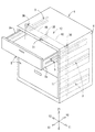
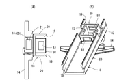
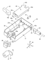
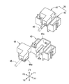
以下に本願発明を実施するための形態を、図面を参照しながら、説明する。図1は什器の(実施例1)としてのキャビネットの斜視図であり、キャビネット本体1内に上下多段(図1では3段で示されている)にわたって配設される抽斗2は各々左右一対のサスペンションレール3,3を介して前後移動自在に懸架される。図1等に示すように、抽斗2の引出し、押し込み方向をX軸方向とし、キャビネット本体1及び抽斗2の間口に沿った方向をY軸方向、家具本体1の上下方向をZ軸方向とする(図1参照)。   EMBODIMENT OF THE INVENTION Below, the form for implementing this invention is demonstrated, referring drawings. FIG. 1 is a perspective view of a cabinet as (Example 1) of a fixture, and drawers 2 arranged in upper and lower multi-stages (shown in three stages in FIG. 1) in the cabinet body 1 are a pair of left and right respectively. It is suspended through suspension rails 3 and 3 so as to be movable back and forth. As shown in FIG. 1 and the like, the drawer 2 is pulled out and pushed in the X-axis direction, the direction along the opening of the cabinet body 1 and the drawer 2 is the Y-axis direction, and the up-and-down direction of the furniture body 1 is the Z-axis direction. (See FIG. 1).

X軸方向に延びる各サスペンションレール3は、キャビネット本体1の左右両側板4,4の補強枠に着脱自在に取付けられる断面横向きコ字型の固定レール3aと、該固定レール3a内に複数の回転コロ5を介して前後動自在に嵌挿された中間レール3bと、抽斗2の左右側板2a,2aから突出する断面L字状の抽斗レール3cとからなる。この抽斗レール3cは前記中間レール3bに設けられた複数の中間コロ6を介して前後移動自在に支持されている(図2参照)。   Each suspension rail 3 extending in the X-axis direction has a U-shaped fixed rail 3a that is detachably attached to the reinforcing frames of the left and right side plates 4 and 4 of the cabinet body 1, and a plurality of rotations within the fixed rail 3a. The intermediate rail 3b is inserted through the roller 5 so as to be movable back and forth, and the drawer rail 3c having an L-shaped cross section projecting from the left and right side plates 2a and 2a of the drawer 2 is formed. The drawer rail 3c is supported so as to be movable back and forth via a plurality of intermediate rollers 6 provided on the intermediate rail 3b (see FIG. 2).

本発明のキャビネットには、後述するように、セーフティロック機構とオールロック機構とを備えている。セーフティロック機構は、1つの抽斗2を引出し動するとき、他の段の引出し動を阻止するための2重引出し防止機構と、複数の抽斗をほぼ同時に引き出すこと実質的に阻止できる、いわゆる同時引出防止機構とのいずれか片方(一方)の機構又は両機構をいう。他方、オールロック機構とは、キャビネット本体1内に全ての抽斗2を押し込んだ状態において錠前をロック操作すると、上記全ての抽斗2の引出し動が阻止される機構をいう。
[2重引出し防止機構]
まず、2重引出し防止機構について説明する。本実施例1では、2重引出し防止機構は、縦杆11に配置され、各段の抽斗2箇所毎に、上面がキャビネット本体1の奥に行くに従って高くなる当接傾斜面に形成されたロック体13と、該ロック体13の下方位置で、下面がキャビネット本体の前に行くに従って下がる第1傾斜案内面15と、該第1傾斜案内面15の下端に連設して前方に延びる水平状の安定面22とを備えた案内体14と、各抽斗のサスペンションレール3の前後移動によって当該サスペンションレール3における中間レールの上面と下向き凹み状案内部とに当接して縦杆11を上下2段階の位置に保持させる落下防止片17とが備えられ、各段の抽斗側板2aの外面には、縦杆11の上昇位置にて当該縦杆11におけるロック体13の後面に突き当ってロックするストッパ体7と、抽斗の引き出し移動時に案内体14における第1傾斜案内面15に当接して後、安定面22に当接することにより、縦杆11と共にロック体13をその後面がストッパ体7の通過を阻止する所定のロック位置まで押し上げる押し上げ体8とが備えられている。
As will be described later, the cabinet of the present invention includes a safety lock mechanism and an all lock mechanism. The safety lock mechanism is a so-called simultaneous drawer in which when one drawer 2 is pulled out, a double drawer preventing mechanism for blocking the drawer movement of the other stage and a plurality of drawers can be substantially pulled out almost simultaneously. This means either one (one) mechanism or both mechanisms of the prevention mechanism. On the other hand, the all-lock mechanism refers to a mechanism that prevents the drawer movement of all the drawers 2 when the lock is locked in a state where all the drawers 2 are pushed into the cabinet body 1.
[Double drawer prevention mechanism]
First, the double drawer preventing mechanism will be described. In the first embodiment, the double drawer prevention mechanism is disposed on the vertical fence 11 and is formed on a contact inclined surface whose upper surface becomes higher toward the back of the cabinet body 1 at every two drawers in each stage. A body 13, a first inclined guide surface 15 whose bottom surface is lowered as it goes in front of the cabinet body at a position below the lock body 13, and a horizontal shape that extends forward by being connected to the lower end of the first inclined guide surface 15. The guide rod 14 having the stable surface 22 and the suspension rail 3 of each drawer move forward and backward to contact the upper surface of the intermediate rail and the downwardly recessed guide portion of the suspension rail 3 to move the vertical rod 11 up and down in two stages. And a drop prevention piece 17 that is held at the position of the vertical side. The outer surface of each side of the drawer side plate 2a is a striking portion that locks against the rear surface of the lock body 13 in the vertical side 11 at the raised position of the vertical side 11. After contacting the first inclined guide surface 15 of the guide body 14 and the guide body 14 during the drawer movement of the drawer body 7, the lock body 13 together with the vertical rod 11 and the rear surface of the stopper body 7 are brought into contact with the stable surface 22. A push-up body 8 that pushes up to a predetermined lock position that prevents passage is provided.

図3及び図4に示す実施形態では、各抽斗2の左右両側板2a,2aから左右両外向きに突出するストッパ体7は、その下面が側面視において抽斗の後寄り位置で高い位置となり、前寄り位置で低い位置となるようにいわゆる前下り傾斜状の下傾斜面7aを備えるように金属板を屈曲形成してものである。また、側面視への字状の押し上げ体8はストッパ体7の下方位置にて金属板に一体的に形成されている。   In the embodiment shown in FIG. 3 and FIG. 4, the stopper body 7 projecting outward from the left and right side plates 2a, 2a of each drawer 2 is located at a high position at the rear side of the drawer in the side view, The metal plate is bent and formed so as to have a lower inclined surface 7a having a so-called front downward inclination so as to be a low position at the front position. The pushing-up body 8 shaped like a side view is integrally formed on the metal plate at a position below the stopper body 7.

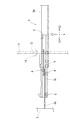
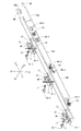
キャビネット本体1における左右両側板4,4の内面に沿ってZ軸方向に上下動できる横断面コ字状の縦杆11は、左右両側板4,4の内面に着脱可能に設けられた断面コ字型のガイド枠9(図17参照)内に沿って配設されている。各縦杆11は各段の抽斗2における固定レール3aの背面と直角方向に交差する。   A vertical saddle 11 having a U-shaped cross section that can move up and down in the Z-axis direction along the inner surfaces of the left and right side plates 4, 4 in the cabinet body 1 is provided in a cross-sectional manner. It is disposed along the letter-shaped guide frame 9 (see FIG. 17). Each vertical fence 11 intersects the back surface of the fixed rail 3a in each stage of the drawer 2 in a direction perpendicular to the fixed rail 3a.

図4、図5(A)、図5(B)、図6及び図7に示すように、ロック体13と、第1傾斜案内面15と第2傾斜案内面16とを有する案内体14と、落下防止片17と、後に詳述する収容体60(請求項にいう収容部材)とは、断面コ字型の取付け基体18に一体的形成されたものである。なお、図5(A)、図5(B)は、キャビネット本体(請求項にいう家具本体に相当)1の左側板4に配置する取付け基体18であって、右側板4に配置する取付け基体18(図3及び図4参照)とは左右対称形状である。取付け基体18はポリアセタール樹脂(POM)等の合成樹脂の射出成形品である。そして、断面コ字型の取付け基体18の内面には、係合爪19を突設し、この係合爪19を縦杆11の所定間隔ごとに穿設された係止孔(図示せず)に嵌め入れ、縦杆11の外周を取付け基体18にて包囲するようにして脱落不能に装着する。   As shown in FIGS. 4, 5 (A), 5 (B), 6 and 7, the lock body 13, the guide body 14 having the first inclined guide surface 15 and the second inclined guide surface 16, The fall prevention piece 17 and the housing body 60 (a housing member referred to in the claims), which will be described in detail later, are integrally formed on the mounting base 18 having a U-shaped cross section. 5 (A) and 5 (B) are mounting bases 18 disposed on the left side plate 4 of the cabinet body (corresponding to the furniture main body in the claims) 1 and are mounted on the right side plate 4. 18 (see FIGS. 3 and 4) is a symmetrical shape. The mounting base 18 is an injection molded product of a synthetic resin such as polyacetal resin (POM). Then, an engagement claw 19 is provided on the inner surface of the U-shaped mounting base 18 and a locking hole (not shown) is formed in the engagement claw 19 at predetermined intervals of the vertical rod 11. The outer periphery of the vertical rod 11 is surrounded by the mounting base 18 so that it cannot be dropped off.

図2〜図4に示すのは、キャビネット本体1の前面から見たとき、キャビネット本体の左側板4の内面に位置した縦杆11に関連するものである。図4(A)、図4(B)に示すように、ロック体13の上面はキャビネット本体1の後方(奥側)に行くに従って高くなる当接傾斜面21を有する。また、案内体14はキャビネット本体1の前方向に行くにしたがって下がる第1傾斜案内面15と該第1傾斜案内面15の下端に連設された水平状の安定面22と、該安定面22の前端に連設し、キャビネット本体1の前方に行くにしたがって順次高くなる第2傾斜案内面16とを備えた横長状の形状である。   2 to 4 are related to the vertical gutter 11 located on the inner surface of the left side plate 4 of the cabinet body when viewed from the front surface of the cabinet body 1. As shown in FIGS. 4 (A) and 4 (B), the upper surface of the lock body 13 has an abutting inclined surface 21 that becomes higher toward the rear (back side) of the cabinet body 1. In addition, the guide body 14 has a first inclined guide surface 15 that descends in the forward direction of the cabinet body 1, a horizontal stable surface 22 that is connected to the lower end of the first inclined guide surface 15, and the stable surface 22. It is a horizontally long shape provided with a second inclined guide surface 16 that is continuously provided at the front end of the main body and that gradually increases toward the front of the cabinet body 1.

さらに、図5(B)及び図5(D)に示すように、取付け基体18の外周面には、ガイド枠(図示せず)の内面に摺接する縦長のスライダ条20が突設されている。この構成により、金属製のガイド枠と縦杆11の側面全体とが直接摺接することがなく、縦杆11の上下動時に静かに且つ滑らかに動き得るものである。他方、各段のサスペンションレール3における固定レール3aの上面前後方向中途部には、中間レール3bの上面が開放される切欠き部23を有する一方、中間レール3bの上面24の前後方向中途部には、適宜深さ寸法(h1:図示せず)だけ落ち込む平坦底面25aと上面24に連通する前後(X軸方向の前後)の傾斜面とから成る落ち込み部25を備える。   Further, as shown in FIGS. 5 (B) and 5 (D), a vertically long slider strip 20 is provided on the outer peripheral surface of the mounting base 18 so as to be in sliding contact with the inner surface of a guide frame (not shown). . With this configuration, the metal guide frame and the entire side surface of the vertical rod 11 are not in direct sliding contact, and can move quietly and smoothly when the vertical rod 11 moves up and down. On the other hand, the suspension rail 3 of each stage has a notch 23 in the middle of the upper surface of the fixed rail 3a in the front-rear direction of the upper surface of the intermediate rail 3b. Is provided with a dip portion 25 composed of a flat bottom surface 25a that falls by an appropriate depth dimension (h1: not shown) and front and rear (front and back in the X-axis direction) inclined surfaces that communicate with the upper surface 24.

そして、前記各段における落下防止片17は、固定レール3aの切欠き部23箇所から中間レール3bの上面に臨むように配設され、且つ各抽斗2がキャビネット本体1に対して押し込み状態のとき、落下防止片17が平坦底面25aに対して当接する状態で嵌まり込んでいる(図3参照)。また、各抽斗2を前向き移動(引き出し動)するにつれて、中間レール3bが前に移動するとき、押し上げ体8が案内体14における第1傾斜案内面15に先に摺接して取付け基体18を介して縦杆11ひいては落下防止片17を徐々に引き上げる(押し上げる)ため、当該落下防止片17が中間レール3bの落ち込み部25における平坦底面25aから後の傾斜状案内面に当接しない状態にて中間レール3bの上面24の箇所まで移動するように構成されている(図4(A)参照)。   The drop prevention pieces 17 in each stage are arranged so as to face the upper surface of the intermediate rail 3b from 23 notches of the fixed rail 3a, and when each drawer 2 is pushed into the cabinet body 1. The fall prevention piece 17 is fitted in a state of being in contact with the flat bottom surface 25a (see FIG. 3). When the intermediate rail 3b moves forward as each drawer 2 is moved forward (drawn), the push-up body 8 first comes into sliding contact with the first inclined guide surface 15 of the guide body 14 via the mounting base 18. In order to gradually lift (push up) the vertical hook 11 and the fall prevention piece 17, the fall prevention piece 17 is intermediate in a state where it does not come into contact with the rear inclined guide surface from the flat bottom surface 25 a in the drop portion 25 of the intermediate rail 3 b. It is comprised so that it may move to the location of the upper surface 24 of the rail 3b (refer FIG. 4 (A)).

このようにして、押し上げ体8が案内体14における水平な安定面22に接当して縦杆8を寸法(h1)だけ押上げ上昇させると、落下防止片17の下端は、中間レール3bの上面24の箇所に摺接可能となり、次いで、抽斗2の引出し動につれて、押し上げ体8が案内体14における水平な安定面22を越えて前方に移動すると、押し上げ体8による案内体14を介しての縦杆11の上昇駆動が解除される。一方、落下防止片17が中間レール3bの上面24に摺接しているので、縦杆11の上昇位置が保持される(図4(B)参照)。   In this way, when the push-up body 8 comes into contact with the horizontal stabilizing surface 22 of the guide body 14 and pushes the vertical rod 8 up by the dimension (h1), the lower end of the fall prevention piece 17 is attached to the intermediate rail 3b. When the push-up body 8 moves forward beyond the horizontal stable surface 22 of the guide body 14 as the drawer 2 is pulled out, the slide body 2 can be slidably contacted with the place of the upper surface 24. Ascending drive of the vertical rod 11 is released. On the other hand, since the fall prevention piece 17 is in sliding contact with the upper surface 24 of the intermediate rail 3b, the raised position of the vertical rod 11 is maintained (see FIG. 4B).

通常の状態では、縦杆11,11は下降した位置にある。この縦杆11における各落下防止片17は各段の中間レール3bにおける平坦底面25a箇所に接当し、ロック体13の上面をストッパ体7が前後方向に通過可能となる。この状態において、図4(A)に示すように、任意の一つの抽斗2を引き出すと、その段のストッパ体7がロック体13の上面を前方に通過する一方、押し上げ体8が案内体14の下面側を通過し、このとき、第1傾斜案内面15を押し上げ体8にて徐々に押し上げる。同時に、中間レール3bが前移動し、それにつれて当該段における落下防止片17が中間レール3bの平坦底面25aから上面24より若干上方に昇り、押上げ体8が案内体14の安定面22に摺接すると縦杆11を寸法(h1)だけ上昇させる(図4(B)参照)。   In the normal state, the downarms 11 are in the lowered position. Each fall prevention piece 17 in the vertical rod 11 comes into contact with the flat bottom surface 25a of the intermediate rail 3b in each stage, and the stopper body 7 can pass through the upper surface of the lock body 13 in the front-rear direction. In this state, as shown in FIG. 4A, when any one of the drawers 2 is pulled out, the stopper body 7 at that stage passes through the upper surface of the lock body 13 while the push-up body 8 is the guide body 14. The first inclined guide surface 15 is gradually pushed up by the push-up body 8 at this time. At the same time, the intermediate rail 3b moves forward, and accordingly, the fall prevention piece 17 at the stage rises slightly above the upper surface 24 from the flat bottom surface 25a of the intermediate rail 3b, and the push-up body 8 slides on the stable surface 22 of the guide body 14. When in contact, the vertical hook 11 is raised by the dimension (h1) (see FIG. 4B).

従って、他の段における押し込み状態の抽斗2の側面におけるストッパ体7の前面に、各々ロック体13の後面が位置することになり、その段の抽斗の前移動を阻止することができ、いわゆる二重引出しを防止してキャビネット本体1の前方向への転倒を防止することができる。そして、前述のように、引き出し動する抽斗2における落下防止体17は、落ち込み部25において、中間レール3bと干渉しないから、当該抽斗2の前移動時にサスペンションレール3の中間レール3bの移動を軽快に保持できるという効果を奏する。   Accordingly, the rear surfaces of the lock bodies 13 are positioned on the front surface of the stopper body 7 on the side surface of the drawer 2 in the pushed state at the other stage, so that the forward movement of the drawer at the stage can be prevented. It is possible to prevent heavy pull-out and prevent the cabinet body 1 from tipping forward. As described above, the fall prevention body 17 in the drawer 2 that moves out does not interfere with the intermediate rail 3b in the sagging portion 25, so that the movement of the intermediate rail 3b of the suspension rail 3 can be simplified during the forward movement of the drawer 2. There is an effect that it can be held.

また、一旦引き出した一つの抽斗2の押し込み動にて、当該押し込み抽斗2におけるストッパ体7の下傾斜面7aが、上昇したロック体13の接当傾斜面21の上を通過すると共に、案内体14の下面側を押し上げ体8が通過し、当該押し上げ体8と案内体14との干渉が外れた状態で、且つ後退する中間レール3bにおける落ち込み部25上に落下防止片17が位置すれば、縦杆11が所定寸法だけ下方移動して下方位置に保持され、元の状態(図3参照)に戻る。なお、前記一旦引き出した一つの抽斗2の押し込み動時に、押し上げ体8が案内体14における前方の第2傾斜案内面16に摺接しながら奥方向に通過するものであっても良い。   In addition, the lower inclined surface 7a of the stopper body 7 in the push-in drawer 2 passes over the contact inclined surface 21 of the raised lock body 13 and is guided by the pushing-in movement of the one drawer 2 once pulled out. If the push-up body 8 passes through the lower surface side of 14 and the interference between the push-up body 8 and the guide body 14 is removed, and the fall prevention piece 17 is positioned on the drop portion 25 in the retreating intermediate rail 3b, The vertical hook 11 moves downward by a predetermined dimension and is held at the lower position, and returns to the original state (see FIG. 3). It should be noted that the push-up body 8 may pass in the back direction while being in sliding contact with the front second inclined guide surface 16 of the guide body 14 at the time of pushing-in movement of the one drawer 2 once pulled out.

縦杆11の落下防止体17が当接(摺接)して縦杆11の上昇状態に保持する位置として、中間レール3bの上面24にすれば、別途部品を必要とせず、部品の省略と取付け作業の省略に一層効果を奏する。
[同時引出防止機構の第1実施例]
次に、複数の抽斗をほぼ同時に引き出すこと実質的に阻止できる、いわゆる同時引出防止機構の構成について説明する。第1実施例として示す図6〜図19は、キャビネット本体1の前面側から見た時の当該キャビネット本体1の右側の縦杆11に関連した個所について示す。従って、第1の水平方向(X軸方向)のうちX1方向は抽斗2の引出し方向であり、X2方向は抽斗2の押込み方向である。
If the top surface 24 of the intermediate rail 3b is used as a position where the fall prevention body 17 of the vertical rod 11 comes into contact (sliding contact) and is held in the raised state of the vertical rod 11, no additional components are required and the components are omitted. It is more effective in omitting the installation work.
[First Embodiment of Simultaneous Drawing Prevention Mechanism]
Next, a configuration of a so-called simultaneous drawer preventing mechanism that can substantially prevent a plurality of drawers from being pulled out almost simultaneously will be described. 6-19 shown as 1st Example show the location relevant to the vertical raft 11 of the right side of the said cabinet main body 1 when it sees from the front side of the cabinet main body 1. FIG. Therefore, in the first horizontal direction (X-axis direction), the X1 direction is the drawing direction of the drawer 2, and the X2 direction is the pushing direction of the drawer 2.

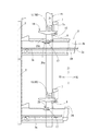
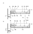
第1実施例では、各取付け基体18のロック体13の下方であって、案内体14よりも上方位置に、抽斗2の側板2aと直交し、且つキャビネット本体1の側板4に向かうように水平に延びる収容部材として収容体60が一体的に形成されている。この収容体10は、縦杆11に穿設された取付け孔61を介してキャビネット本体1の側板4の内面に近づくように嵌め込む。また、この収容体60には抽斗2の側板2aと対面するように矩形状のガイド穴40が穿設されている(図7、図8、図9参照)。   In the first embodiment, below the lock body 13 of each mounting base 18 and above the guide body 14, it is horizontal so as to be orthogonal to the side plate 2 a of the drawer 2 and toward the side plate 4 of the cabinet body 1. A housing 60 is integrally formed as a housing member extending in the direction. The container 10 is fitted so as to approach the inner surface of the side plate 4 of the cabinet body 1 through an attachment hole 61 formed in the vertical rod 11. The container 60 is provided with a rectangular guide hole 40 so as to face the side plate 2a of the drawer 2 (see FIGS. 7, 8, and 9).

ガイド穴40には作動体62が抽斗2の側板2aに対して直交し且つ水平方向に進退動可能、つまりY軸方向に移動可能に収容されている(図7、図8(B)、図9〜図11参照)。また、収容体60は、その内部に作動体62と、支持体63と、上下一対の作動追従体64、65(請求項にいう第1及び第2の作動追従体)とが相対的に移動可能となるような立方状の収容空間を有する箱体である。これらの部品である取付け基体18、作動体62、支持体63、上下一対の作動追従体64、65は、ポリアセタール樹脂製等の合成樹脂製の射出成形品である。   The operating body 62 is accommodated in the guide hole 40 so as to be perpendicular to the side plate 2a of the drawer 2 and to be movable back and forth in the horizontal direction, that is, to be movable in the Y-axis direction (FIGS. 7 and 8B). 9 to 11). The container 60 has a working body 62, a support body 63, and a pair of upper and lower operation followers 64 and 65 (first and second action followers in the claims) relatively moved therein. It is a box having a cubic accommodation space that is possible. The mounting base 18, the operating body 62, the support body 63, and the pair of upper and lower operation followers 64 and 65, which are these parts, are injection molded products made of synthetic resin such as polyacetal resin.

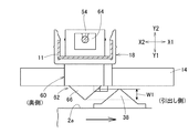
作動体62における先端部66は、各段の抽斗2の側板2aと対面するように設けられている。作動体62における先端部66は、平面視で矢印形状(二等辺三角形状)である。各抽斗2の側板2a外面には、平面視で二等辺三角形状の突起部38が固定されている(図6参照)。突起部38は、各作動体62における先端部66の配置高さ位置と同じ高さに設けられている。   The distal end portion 66 of the operating body 62 is provided so as to face the side plate 2a of the drawer 2 at each stage. The distal end portion 66 of the operating body 62 has an arrow shape (isosceles triangle shape) in plan view. An isosceles triangular projection 38 is fixed to the outer surface of the side plate 2a of each drawer 2 in plan view (see FIG. 6). The protrusion 38 is provided at the same height as the arrangement height position of the tip 66 in each operating body 62.

各作動体62における先端部66の後側には、フランジ部68を介して後向きに延びる断面矩形状の作動片67が一体的に形成されている。作動片67の後端には、高さ方向の中央部で一番奥側となり、上方及び下方に行くに従って前方に傾斜する一対の傾斜摺接面からなる押上げ部70と、押下げ部71とが設けられている(図9参照)。   An operating piece 67 having a rectangular cross section extending rearward through a flange portion 68 is integrally formed on the rear side of the distal end portion 66 of each operating body 62. At the rear end of the operating piece 67, there is a push-up portion 70 consisting of a pair of inclined sliding contact surfaces that are the farthest in the center in the height direction and incline forward as it goes upward and downward, and a push-down portion 71 Are provided (see FIG. 9).

収容体60の後側(奥側)の内部に挿入して固定される支持体63は、略直方体の後向き開放状の箱体である。支持体63には、作動体62における作動片67を進退動可能に支持できる支持孔73を有する支持部72と、この支持部72の奥側の外面に設けられた一対の係止爪(図示せず)と、上下一対の作動追従体64、65を上下スライド可能に支持できる支持孔76、75とを備えている。   The support body 63 that is inserted and fixed inside the rear side (back side) of the housing body 60 is a box that is open to the rear and is substantially a rectangular parallelepiped. The support 63 has a support portion 72 having a support hole 73 that can support the operating piece 67 of the operating body 62 so as to be able to advance and retreat, and a pair of locking claws provided on the outer surface on the back side of the support portion 72 (see FIG. And support holes 76 and 75 that can support a pair of upper and lower operation followers 64 and 65 so as to be slidable up and down.

まず、先端部66を先にして作動体62を収容体60の奥側から内部に挿入した後、圧縮コイルバネ77を挿入し、さらに、支持部72を先にして支持体63を同じく挿入すると、一対の係止爪(図示せず)が収容体60の左右両側面の係止孔82に係合して脱落不能となる。このとき、収容体60の上下面に穿設された孔83と挿入された支持体63の上下の支持孔76、75との位置が一致する。そして、支持孔73に挿通した作動片67の外周に被嵌した付勢手段としての圧縮コイルバネ77は作動体62における先端部66と支持部72とに支持される(図9、図10等参照)。   First, after inserting the operating body 62 into the interior from the back side of the housing body 60 with the tip portion 66 first, the compression coil spring 77 is inserted, and when the support body 63 is also inserted with the support portion 72 first, A pair of locking claws (not shown) engages with the locking holes 82 on the left and right side surfaces of the container 60 so that they cannot be removed. At this time, the positions of the holes 83 formed in the upper and lower surfaces of the container 60 and the upper and lower support holes 76 and 75 of the inserted support 63 coincide with each other. And the compression coil spring 77 as an urging means fitted on the outer periphery of the operating piece 67 inserted through the support hole 73 is supported by the distal end portion 66 and the support portion 72 of the operating body 62 (see FIG. 9, FIG. 10, etc.). ).

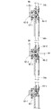
上下一対の作動追従体64、65は同一形態であり、上下対称状に配置すれば良い。上側の作動追従体64について説明する。図10に示すように、その細径部64aの片面(前面)には、側面視で、下方に行くに従って後向きに傾斜する傾斜摺接面78が形成され、作動追従体64の太径部64bにはロッド54bの下端を嵌め込んで支持するための支持孔79が設けられている。従って、中段における下側の作動追従体65に関しては、細径部64aの片面(前面)に傾斜摺接面78が形成され、支持孔79にはロッド54aの上端が嵌まることになる。   The pair of upper and lower operation followers 64 and 65 have the same form and may be arranged symmetrically in the vertical direction. The upper action follower 64 will be described. As shown in FIG. 10, an inclined sliding contact surface 78 is formed on one surface (front surface) of the small-diameter portion 64a so as to incline backward in a side view, and the large-diameter portion 64b of the operation follower 64 is formed. Is provided with a support hole 79 for fitting and supporting the lower end of the rod 54b. Accordingly, with respect to the lower operation follower 65 in the middle stage, the inclined sliding contact surface 78 is formed on one surface (front surface) of the small diameter portion 64a, and the upper end of the rod 54a is fitted into the support hole 79.

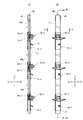
図1、図8(A)及び図8(B)に示すように、キャビネット本体1に対して抽斗2を上下3段に配置する場合、下段、中段、上段の各抽斗2の高さ位置に対応させて、取付け基体18、ひいては収容体60及び作動体62が配置される。これらの部品はポリアセタール樹脂(POM)等の合成樹脂の射出成形品である。ロッド54c、54b、54aは金属製であっても良い。以下では、下段、中段、上段の取付け基体18、収容体60、作動体62及び、第1、第2の作動追従体64、65に対して添え数字1、2、3を附して区別することにする。下段の抽斗2と中段の抽斗2とに対応する高さ位置に、縦杆11の裏面側にて上下に延びる丸棒などのロッド54c、54b、54aが配置されることになる。換言すると、下段の取付け基体18−1と中段の取付け基体18−2と間に第1のロッド54aが配置され、且つ下段の第1の作動追従体64−1の支持孔79に第1のロッド54aの下端が嵌まると共に、中段の第2の作動追従体65−1の支持孔79に第1のロッド54aの上端が嵌まる。中段の取付け基体18−2と上段の取付け基体18−3と間に第2のロッド54bが配置されて、中段の第1の作動追従体64−2の支持孔79に第2のロッド54bの下端が嵌まり、上段の第2の作動追従体65−3の支持孔79に第2のロッド54bの上端が嵌まる。そして、上段の第1の作動追従体64−3には第3のロッド54cの下端が嵌まる。これらロッド54c、54b、54aは作動追従体64、65に対して着脱可能に取付けられている。なお、下段の収容体60より下方にはロッドが存在しない。   As shown in FIG. 1, FIG. 8 (A) and FIG. 8 (B), when the drawers 2 are arranged in three upper and lower stages with respect to the cabinet body 1, the heights of the lower, middle and upper drawers 2 are set. Correspondingly, the mounting base 18, and thus the container 60 and the operating body 62 are arranged. These parts are injection molded products of synthetic resin such as polyacetal resin (POM). The rods 54c, 54b, 54a may be made of metal. Hereinafter, the lower base, the middle stage, and the upper stage mounting base 18, the housing body 60, the operating body 62, and the first and second operating followers 64 and 65 will be distinguished by attaching the additional numbers 1, 2, and 3. I will decide. Rods 54c, 54b, 54a such as round bars extending vertically on the back side of the vertical rod 11 are arranged at height positions corresponding to the lower drawer 2 and the middle drawer 2. In other words, the first rod 54 a is arranged between the lower mounting base 18-1 and the middle mounting base 18-2, and the first rod is inserted into the support hole 79 of the lower first operation follower 64-1. The lower end of the rod 54a is fitted, and the upper end of the first rod 54a is fitted into the support hole 79 of the second operation follower 65-1 in the middle stage. The second rod 54b is disposed between the middle mounting base 18-2 and the upper mounting base 18-3, and the second rod 54b is inserted into the support hole 79 of the first first operation follower 64-2. The lower end is fitted, and the upper end of the second rod 54b is fitted into the support hole 79 of the upper second operation follower 65-3. And the lower end of the 3rd rod 54c fits into the 1st operation follower 64-3 of the upper stage. These rods 54c, 54b, 54a are detachably attached to the operation followers 64, 65. There is no rod below the lower container 60.

[初期状態]
上記の構成において、上下3段のすべての抽斗2がキャビネット本体1内に押し込まれた状態では、図8(A)及び図8(B)に示すように、全ての作動体62の先端部66が抽斗2の側板2aに接近する姿勢にある。なお、図9は中段の抽斗に対応する収容体60−2及び作動体62−2と、上段の抽斗に対応する収容体60−3及び作動体62−3等の拡大側断面図である。
[initial state]
In the above configuration, when all the upper and lower three-stage drawers 2 are pushed into the cabinet body 1, as shown in FIGS. 8A and 8B, the tip portions 66 of all the operating bodies 62 are provided. Is in a posture approaching to the side plate 2 a of the drawer 2. FIG. 9 is an enlarged side sectional view of the container 60-2 and the operating body 62-2 corresponding to the middle drawer, the container 60-3 and the actuator 62-3 corresponding to the upper drawer, and the like.

圧縮コイルバネ77の付勢力にて、全ての段の作動体62はその先端部66が抽斗2の側板2aに接近する方向(図8(B)、図9のY2の方向)に付勢されている。従って、各抽斗2の引出し動(図8(A)のX1方向の動き)及び押し込み動(図8(A)のX2方向の動き)に応じて、突起部38の一方(または他方)の斜面で作動体62における先端部66の一方(または他方)の斜面を押圧している間のみ、作動体62を(図10でY1方向)に、最大距離W1だけ後退させることができる。   By the urging force of the compression coil spring 77, the actuating bodies 62 of all stages are urged in the direction in which the tip 66 approaches the side plate 2a of the drawer 2 (the direction of Y2 in FIG. 8B and FIG. 9). Yes. Accordingly, one (or the other) slope of the protrusion 38 according to the drawing movement (movement in the X1 direction in FIG. 8A) and pushing movement (movement in the X2 direction in FIG. 8A) of each drawer 2. Thus, the operating body 62 can be retracted by the maximum distance W1 (in the Y1 direction in FIG. 10) only while one (or the other) slope of the distal end portion 66 of the operating body 62 is being pressed.

そして、全ての段の作動体62における作動片67の上側の傾斜摺接面である押上げ部70が第1の作動追従体64の傾斜摺接面78に近接している(図9参照)。また、この状態では、中段の収容体60−2及び上段の収容体60−3の下面側の孔83及び支持孔75には、第2の作動追従体65−2、65−3が上向きに挿入されている。それらの上端の高さ位置が、対応する作動体62−2、62−3における作動片67の下面の高さ位置より若干低い位置に保持されている(図9参照)。   And the raising part 70 which is the inclination sliding contact surface of the upper side of the action | operation piece 67 in the action body 62 of all the steps is adjoining to the inclination sliding contact surface 78 of the 1st action follower 64 (refer FIG. 9). . In this state, the second operation followers 65-2 and 65-3 face upward in the holes 83 and the support holes 75 on the lower surface side of the middle container 60-2 and the upper container 60-3. Has been inserted. The height positions of these upper ends are held at positions slightly lower than the height positions of the lower surfaces of the operating pieces 67 in the corresponding operating bodies 62-2 and 62-3 (see FIG. 9).

[補助的2重引出し防止の作用]
上記の状態にて、1つの段、例えば中段の抽斗2のみ引出し動させると、図10に示すように、中段の突起部38にて押圧された中段の作動体62−2は、圧縮コイルバネ77の付勢力に抗して、収納体60−2内で大きくY1方向に後退できる。作動体62−2が最大距離W1だけ後退すると、作動体62−2のフランジ部68が支持体63の前縁63aに当接してそれ以上後退することができない。
[Action of preventing auxiliary double drawer]
When only one stage, for example, the middle stage drawer 2 is pulled out in the above state, the middle stage actuating body 62-2 pressed by the middle stage projection 38 is compressed coil spring 77 as shown in FIG. Against the urging force, it can be largely retracted in the Y1 direction within the storage body 60-2. When the operating body 62-2 is retracted by the maximum distance W1, the flange portion 68 of the operating body 62-2 is brought into contact with the front edge 63a of the support body 63 and cannot be further retracted.

そして、中段の作動体62−2の押上げ部70の傾斜摺接面にて第1の作動追従体64−2の傾斜摺接面78を押圧して、当該第1の作動追従体64−2をH3の高さだけZ1方向に上昇させる。そして、押し込まれた中段の作動体62−2における作動片67の下面が第2の作動追従体65−2の上面側を塞ぐので、第2の作動追従体65−2ひいてはロッド54aの上昇を阻止するようになる(図10参照)。そうすると、図10で図示していないが、下段の作動体62−1が下段の抽斗2の突起部38にて押圧されて後退しようとしても、第1のロッド54aの上昇が阻止されているため、これ以上、下段の作動体62−1は後退できないことになる。同様に、中段の作動体62−2の押し上げ部70にて第1の作動追従体64−2をH3の高さだけ上昇させると、この作動追従体64−2に支持された第2のロッド54bの上端の第2の作動追従体65−3(上段)は、上段における収納体60−3及び支持体63内に突出し、H3の高さだけ押し上げられることになる。   Then, the inclined sliding contact surface 78 of the first operation follower 64-2 is pressed by the inclined sliding contact surface of the push-up portion 70 of the middle working member 62-2, and the first operation follower 64- 2 is raised in the Z1 direction by the height of H3. And since the lower surface of the operating piece 67 of the pushed middle stage operating body 62-2 closes the upper surface side of the second operation following body 65-2, the second operation following body 65-2 and then the rod 54a is lifted. (See FIG. 10). Then, although not shown in FIG. 10, even if the lower actuating body 62-1 is pressed by the protrusion 38 of the lower drawer 2 and tries to move backward, the first rod 54a is prevented from rising. Further, the lower actuating body 62-1 cannot move backward. Similarly, when the first operation follower 64-2 is raised by the height of H3 by the push-up portion 70 of the middle-stage operation body 62-2, the second rod supported by the operation follower 64-2 The second operation follower 65-3 (upper stage) at the upper end of 54b protrudes into the storage body 60-3 and the support body 63 in the upper stage, and is pushed up by the height of H3.

しかして、上段における作動体62−3の作動片67が後退しようとするとき、上昇状態の第2のロッド54bの側面に邪魔されて、後退できなくなるから、上段の抽斗2の突起部38にて押圧されて上段における作動体62−3が後退することを阻止されるのである。下段の作動体62−1が先に押し込まれた場合も同様の作用で、中段及び上段の抽斗の引き出し動は一時的に阻止できる。これらが補助的な2重引出し防止の作用となる。   Accordingly, when the operating piece 67 of the operating body 62-3 in the upper stage is going to be retracted, it is obstructed by the side surface of the raised second rod 54b and cannot be retracted. Thus, the actuator 62-3 in the upper stage is prevented from moving backward. When the lower actuating element 62-1 is pushed in first, the same action can be used to temporarily prevent the middle and upper drawers from being pulled out. These serve as an auxiliary double drawer preventing action.

同様に、上段の抽斗2のみを先に引き出すと、上段の突起部38にて押圧された上段の作動体62−3は、圧縮コイルバネ77の付勢力に抗して、収納体60−3内で大きくY1方向に後退する。作動体62−3が最大距離W1だけ後退すると、作動体62−3のフランジ部68が支持体63の前縁63aに当接してそれ以上後退することができない。後退した状態の作動体62−3の作動片67における押上げ部70の傾斜摺接面にて第1の作動追従体64−3の傾斜摺接面78を押圧して、当該第1の作動追従体64−3をH3の高さだけZ1方向に上昇させる。他方、作動片67の下面が第2のロッド54bの上端の第2の作動追従体65−3の上面を塞いだ状態となるので、第2のロッド54bも、初期状態のままこれ以上上昇させることができない。即ち、それぞれの段の第1、及び第2の作動追従体64、65は上下動不能であるので、中段または、下段の作動体62−1、62−2が後退することを一時的に阻止されるのである。しかして、これによっても補助的な2重引出し防止の作用を発揮できる。   Similarly, when only the upper drawer 2 is pulled out first, the upper actuating body 62-3 pressed by the upper projecting portion 38 resists the urging force of the compression coil spring 77 in the housing 60-3. To move backward in the Y1 direction. When the actuating body 62-3 is retracted by the maximum distance W1, the flange portion 68 of the actuating body 62-3 abuts on the front edge 63a of the support 63 and cannot be further retracted. The first slidable contact surface 78 of the first operation follower 64-3 is pressed by the inclined slidable contact surface of the push-up portion 70 of the operating piece 67 of the operating body 62-3 in the retracted state, and the first operation. The follower 64-3 is raised in the Z1 direction by the height of H3. On the other hand, since the lower surface of the operating piece 67 is in a state of closing the upper surface of the second operation follower 65-3 at the upper end of the second rod 54b, the second rod 54b is also raised further in the initial state. I can't. That is, since the first and second operation followers 64 and 65 of each stage cannot move up and down, the middle or lower stage actuators 62-1 and 62-2 are temporarily prevented from moving backward. It is done. Therefore, this can also exert an effect of preventing auxiliary double drawing.

上記の作用は、各抽斗2における突起部38が作動体62の先端部66を押圧している間のみ発揮されるのであって、突起部38が作動体62の先端部66の個所を通過してしまうと、上記の作用は発揮できない。上述した2重引出し防止機構の存在により、確実な2重引出し防止作用を発揮することができる。   The above action is exhibited only while the projections 38 in each drawer 2 press the tip portion 66 of the operating body 62, and the projection portion 38 passes through the position of the tip portion 66 of the operating body 62. If this happens, the above action cannot be exhibited. Due to the presence of the double-drawing prevention mechanism described above, a reliable double-drawing prevention function can be exhibited.

[同時引出防止の作用]
次に、複数段の抽斗2をほぼ同時に引き出すことを阻止できる作用について、図11を参考にしながら説明する。図11は中段と上段の抽斗2をほぼ同時に引き出す場合の作用説明図であって、中段の抽斗2の突起部38が作動体62−2の先端部66を押して、当該作動体62−2を少量W4の距離だけ後退させたとする。この後退により、中段の作動体62−2の押上げ部70(傾斜摺接面)にて第1の作動追従体64−2をH4(上記H3のほぼ半分の量)の高さだけ上昇させる。すると、この作動追従体64−2に支持された第2のロッド54bの上端の第2の作動追従体65−3の傾斜摺接面78は、上段の収納体60−3における支持体63内に上方に突出し、上段における作動体62−3の作動片67の後端が、上記傾斜摺接面78に当接してそれ以上後退することができない。即ち、上段の抽斗2の突起部38が上段の作動体62−3の先端部66を押しても、この作動体62−3も上記少量W4の距離だけしか後退できない。
[Action of preventing simultaneous withdrawal]
Next, an operation capable of preventing the plurality of drawers 2 from being pulled out almost simultaneously will be described with reference to FIG. FIG. 11 is a diagram for explaining the operation when the middle and upper drawers 2 are pulled out almost simultaneously. The projection 38 of the middle drawer 2 pushes the distal end portion 66 of the working body 62-2, thereby moving the working body 62-2. It is assumed that the vehicle is moved backward by a small distance W4. By this retreat, the first operation follower 64-2 is raised by the height of H4 (substantially half the amount of H3) at the push-up portion 70 (inclined sliding contact surface) of the middle stage actuating body 62-2. . Then, the inclined sliding contact surface 78 of the second operation follower 65-3 at the upper end of the second rod 54b supported by the operation follower 64-2 is in the support 63 in the upper storage body 60-3. The rear end of the actuating piece 67 of the actuating body 62-3 in the upper stage cannot contact the inclined sliding contact surface 78 and move back further. That is, even if the protrusion 38 of the upper drawer 2 pushes the tip 66 of the upper working body 62-3, the working body 62-3 can also move backward only by the small amount W4.

同様に、中段における作動体62−2をW4の距離だけ後退させると、第2の作動追従体65−2の傾斜摺接面78と、作動片67の後端の傾斜摺接である押下げ部71と隙間に対応して第2の作動追従体65−2は上記H4の高さだけ上昇可能であるが、この程度の上昇では、下段の作動体62−1を少量W4の距離だけ後退できる程度に下段の第2の作動追従体65−1が上昇するだけである。しかして、2段以上の抽斗2をほぼ同時に引き出すことは確実に防止することができる。   Similarly, when the actuating body 62-2 in the middle stage is retracted by a distance of W4, the inclined sliding contact surface 78 of the second operating follower 65-2 and the downward sliding contact of the rear end of the operating piece 67 are pushed down. The second operation follower 65-2 can be raised by the height of H4 corresponding to the gap between the portion 71 and the gap, but with this rise, the lower actuator 62-1 is retracted by a small distance W4. The lower second operation follower 65-1 only rises as much as possible. Thus, it is possible to reliably prevent the drawers 2 having two or more stages from being pulled out almost simultaneously.

本発明の同時引出防止機構としての収容体60は、引き出し動及び押込み動する各段の抽斗2における突起部38と同じ高さ位置のキャビネット本体1の側板4に高さの変化しない状態で設けられていても良い。上記のように昇降動可能な縦杆11に、収容体60を設けることができる。その場合、上述の2重引出し防止機構における取付け基体18に収容体60を一体的に形成すれば、複数の必要部品をまとめて、構成をコンパクトにできる効果を有する。上記セーフティロック機構におけるロッド54c、54b、54aは、請求項にいう昇降体である。   The container 60 as the simultaneous drawer preventing mechanism of the present invention is provided in a state in which the height does not change on the side plate 4 of the cabinet body 1 at the same height as the protrusion 38 in the drawer 2 of each stage that is pulled out and pushed in. It may be done. The container 60 can be provided on the vertical rod 11 that can be moved up and down as described above. In that case, if the housing 60 is integrally formed on the mounting base 18 in the double drawer preventing mechanism described above, there is an effect that a plurality of necessary parts can be integrated and the configuration can be made compact. The rods 54c, 54b, 54a in the safety lock mechanism are lifting bodies as defined in the claims.

[オールロック機構]
次に、全ての段の抽斗2をキャビネット本体1内に押し込んだ状態にて、錠前31のロック操作により、当該全ての抽斗の引出し動を阻止するオールロック機構12の実施例について説明する。図12〜図19はその第1実施例を示す。
[All-lock mechanism]
Next, an embodiment of the all-lock mechanism 12 that prevents all drawers from being pulled out by the lock operation of the lock 31 in a state where all the drawers 2 are pushed into the cabinet body 1 will be described. 12 to 19 show the first embodiment.

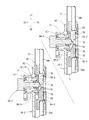
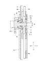
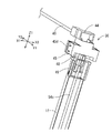
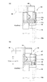
図1にて概略示し、後に詳述するように、オールロック機構12は、キャビネット本体1の天板の前面に取付く錠前31と、キーにより施錠及び解錠するとき錠前31のデッドボルト32の上下回動(又は上下出没動)に押されて第1の水平方向と第2の水平方向とに作動する第1連動部35と、この第1連動部35に接続された第2連動部36とを介して最上位置のロッド54c(昇降体)の上昇の動作を阻止するものである。なお、錠前31は最上段の抽斗2の前面板(鏡板)に取付けて、キーにより施錠するとき、錠前31のデッドボルト32がキャビネット本体1の天板の下面方向に突出する構成であっても良い。   As schematically shown in FIG. 1 and described in detail later, the all lock mechanism 12 includes a lock 31 attached to the front surface of the top plate of the cabinet body 1 and a dead bolt 32 of the lock 31 when locked and unlocked with a key. A first interlocking portion 35 that is pushed by vertical rotation (or up and down movement) and operates in the first horizontal direction and the second horizontal direction, and a second interlocking portion 36 connected to the first interlocking portion 35. Are used to prevent the uppermost rod 54c (lifting body) from moving up. Even if the lock 31 is attached to the front plate (end plate) of the uppermost drawer 2 and locked with a key, the dead bolt 32 of the lock 31 protrudes toward the lower surface of the top plate of the cabinet body 1. good.

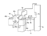
図12〜図14は第1連動部35の第1実施例を示し、ポリアセタール樹脂(POM)等の合成樹脂製などの筐体37の前側には、Z方向(垂直方向)に昇降可能な第1ブロック体38を昇降可能に支持する第1案内支持部39が形成されている。ロック操作時に上昇するデッドボルト32が第1ブロック体38の前端下面に当接して第1ブロック体38全体をZ方向(垂直方向)に押し上げる。第1ブロック体38の後端には、後下向き傾斜する第1傾斜摺接部38aが形成されている。   FIGS. 12 to 14 show a first embodiment of the first interlocking portion 35. The front side of a housing 37 made of synthetic resin such as polyacetal resin (POM) is movable up and down in the Z direction (vertical direction). A first guide support portion 39 is formed to support the one block body 38 so as to be movable up and down. The dead bolt 32 that rises during the locking operation contacts the lower surface of the front end of the first block body 38 to push up the entire first block body 38 in the Z direction (vertical direction). A first inclined sliding contact portion 38 a that is inclined rearward and downward is formed at the rear end of the first block body 38.

筐体37内の底板37aには、第1の水平方向(Y軸方向)に延びるように突設された2つのガイドレール37bの間で第1の水平方向(Y軸方向)に移動可能な第2ブロック体40が摺動自在に支持されている。なお、各ガイドレール37bには第2ブロック体40の浮き上がり防止規制爪37cが設けられている。第2ブロック体40の前端部40aは第1案内支持部39に形成された窓孔39aに嵌め入れられている。第2ブロック体40の前端部40aの下面には、前上向き傾斜の第2傾斜摺接部40bが形成されている。第2ブロック体40の後端部と筐体37の後板との間に配置された付勢手段であるコイルばね41により、第2傾斜摺接部40bは第1傾斜摺接部38aと常時当接して摺接可能となっている(図12、図14(A)及び図14(B)参照)。   The bottom plate 37a in the housing 37 is movable in the first horizontal direction (Y-axis direction) between two guide rails 37b protruding so as to extend in the first horizontal direction (Y-axis direction). The second block body 40 is slidably supported. Each guide rail 37b is provided with a lifting prevention regulating claw 37c for the second block body 40. The front end portion 40 a of the second block body 40 is fitted into a window hole 39 a formed in the first guide support portion 39. A second inclined sliding contact portion 40b that is inclined forward and upward is formed on the lower surface of the front end portion 40a of the second block body 40. The second inclined sliding contact portion 40b is always connected to the first inclined sliding contact portion 38a by a coil spring 41 which is an urging means disposed between the rear end portion of the second block body 40 and the rear plate of the housing 37. It can be slidably contacted (see FIG. 12, FIG. 14 (A) and FIG. 14 (B)).

第2ブロック体40の後部には、左右一対の第3傾斜摺接部40cが形成されている。左右一対の第3傾斜摺接部40cは、後方に行くに従って第2ブロック体40の左右中央側に近づく(逆に言えば、前側が第2ブロック体40の左右側方に向かって広がる)ように平面視で矢印状に形成されている(図12、図13参照)。   A pair of left and right third inclined sliding contact portions 40 c are formed at the rear portion of the second block body 40. The pair of left and right third inclined sliding contact portions 40c approach the left and right central sides of the second block body 40 as going backward (in other words, the front side spreads toward the left and right sides of the second block body 40). Are formed in an arrow shape in plan view (see FIGS. 12 and 13).

左右一対の第3ブロック体42は、第2の水平方向(X軸方向)に沿って移動可能なように、筐体37の底板37aに支持され、第3ブロック体42の一部は筐体37の側板に穿設されたガイド孔43を介して左右外側に突出している。左右一対の第3ブロック体42は第2ブロック体40の後端に対して第2の水平方向(X軸方向)に延びるように配置されている。第3ブロック体42における第4傾斜摺動部42aは、先端側に行くにしたがって、第1の水平方向(Y軸方向)でキャビネット本体1の奥側に向かうように傾斜しており、第4傾斜摺動部42aと第2ブロック体40の第3傾斜摺接部40cとが常時当接しているように形成されている。そして、第2ブロック体40が第1の水平方向(Y軸方向)に沿い且つキャビネット本体1の奥側に向かうように移動する時(ロック動作方向に移動する時)には、左右一対の第3ブロック体42は、第2の水平方向(X軸方向)に沿い、且つ互いに離間する方向に移動するように構成されている(図12参照)。第1〜第3ブロック体38、40、42はポリアセタール樹脂(POM)等の摩擦係数が小さく、且つ剛性を有する合成樹脂製である。   The pair of left and right third block bodies 42 are supported by the bottom plate 37a of the housing 37 so as to be movable along the second horizontal direction (X-axis direction), and a part of the third block body 42 is a housing. It projects to the left and right outside through a guide hole 43 formed in the side plate 37. The pair of left and right third block bodies 42 are disposed so as to extend in the second horizontal direction (X-axis direction) with respect to the rear end of the second block body 40. The 4th inclination sliding part 42a in the 3rd block body 42 inclines so that it may go to the back | inner side of the cabinet main body 1 in the 1st horizontal direction (Y-axis direction) as it goes to the front end side. The inclined sliding portion 42a and the third inclined sliding contact portion 40c of the second block body 40 are formed so as to be in constant contact with each other. When the second block body 40 moves along the first horizontal direction (Y-axis direction) and toward the back side of the cabinet body 1 (when moving in the locking operation direction), a pair of left and right first The three block bodies 42 are configured to move along the second horizontal direction (X-axis direction) and away from each other (see FIG. 12). The first to third block bodies 38, 40 and 42 are made of a synthetic resin having a small friction coefficient and rigidity such as polyacetal resin (POM).

第2連動部36は、キャビネット本体1の左右両側板4の内面に沿って上下に延びるように配置された昇降体であるロッドのうち最上位置(第3)のロッド54cの上端側に近接させて配置させている。図15〜図19に示す実施例では、第2連動部36は、ストッパ体44と、このストッパ体44を第2の水平方向(X軸方向)に沿って移動可能となるように支持する支持ケース45とからなり、これらはポリアセタール樹脂(POM)等の合成樹脂製である。そして、ストッパ体44と上記第3ブロック体42とは第2の水平方向に沿って延びる丸棒等の連結杆46にて連結されている。   The second interlocking part 36 is made close to the upper end side of the uppermost position (third) rod 54c among the rods which are lifting and lowering bodies arranged so as to extend vertically along the inner surfaces of the left and right side plates 4 of the cabinet body 1. Are arranged. In the embodiment shown in FIGS. 15 to 19, the second interlocking portion 36 supports the stopper body 44 and the stopper body 44 so as to be movable along the second horizontal direction (X-axis direction). The case 45 is made of a synthetic resin such as polyacetal resin (POM). The stopper body 44 and the third block body 42 are connected by a connecting rod 46 such as a round bar extending along the second horizontal direction.

支持ケース45には、ストッパ体44をX軸方向に沿ってのみ移動可能に案内するガイドレール部45aと、このガイドレール部45aに隣接して下方に貫通する挿通孔45bと、ストッパ体44を第3ブロック体42に近づく方向に付勢するコイルばね47(付勢手段)の一端を支持する凹み座部45cとが形成されている(図17〜図19参照)。水平な一対のガイドレール部45aは支持ケース45の内径部に相対向して設けられ、ストッパ体44には一対のガイドレール部45aに嵌まる水平な案内溝44aが設けられている。支持ケース45の外面に形成されている一対の係合爪45dを金属板製のガイド枠9に穿設された係合孔9aに嵌め入れて抜け不能に位置固定させている(図17参照)。   The support case 45 includes a guide rail portion 45a for guiding the stopper body 44 so as to be movable only along the X-axis direction, an insertion hole 45b penetrating downward adjacent to the guide rail portion 45a, and the stopper body 44. A recessed seat 45c that supports one end of a coil spring 47 (biasing means) that urges in the direction approaching the third block body 42 is formed (see FIGS. 17 to 19). The pair of horizontal guide rail portions 45a are provided opposite to the inner diameter portion of the support case 45, and the stopper body 44 is provided with a horizontal guide groove 44a that fits into the pair of guide rail portions 45a. A pair of engagement claws 45d formed on the outer surface of the support case 45 are fitted into engagement holes 9a formed in a guide frame 9 made of a metal plate, and are fixed so that they cannot be removed (see FIG. 17). .

他方、ロッド54cの上端には、当接ブロック48が着脱可能に設けられている。そして、縦杆11の先端(上端)には、案内枠体49が取付けられ、案内枠体49には当接ブロック48の上下動を案内する案内孔49aが形成されている(図7、図8、図16、図17参照)。なお、第1連動部35の筐体37、連結杆46、第2連動部36の支持ケース45の下面側は、図示していないカバー板にて覆われて、ユーザが容易に触れられないようにしている。   On the other hand, a contact block 48 is detachably provided at the upper end of the rod 54c. A guide frame body 49 is attached to the tip (upper end) of the vertical rod 11, and a guide hole 49a for guiding the vertical movement of the contact block 48 is formed in the guide frame body 49 (FIGS. 7 and 7). 8, FIG. 16, FIG. 17). The casing 37 of the first interlocking portion 35, the connecting rod 46, and the lower surface side of the support case 45 of the second interlocking portion 36 are covered with a cover plate (not shown) so that the user cannot easily touch them. I have to.

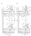
上記の構成により、全ての段の抽斗2がキャビネット本体1内に押し込まれた状態にあるときには、図19(A)に示すように、縦杆11が下降位置にあり、且つロッド54c(当接ブロック48)も下降位置にある。また、錠前31が非ロック状態のときには、第1連動部35における第2ブロック体40はコイルばね41にてキャビネット本体1の前面側に移動するように付勢されている。従って、第2傾斜摺接部40bが第1傾斜摺接部38aを前方に押すので、第1ブロック体38は下降位置に保持されている(図14(A)参照)。   With the above configuration, when all the drawers 2 are pushed into the cabinet body 1, as shown in FIG. 19 (A), the vertical rod 11 is in the lowered position and the rod 54c (contact) Block 48) is also in the lowered position. When the lock 31 is in the unlocked state, the second block body 40 in the first interlocking portion 35 is biased by the coil spring 41 so as to move to the front side of the cabinet body 1. Accordingly, since the second inclined sliding contact portion 40b pushes the first inclined sliding contact portion 38a forward, the first block body 38 is held at the lowered position (see FIG. 14A).

上記の状態で、錠前31をロック操作すると、図14(B)に示すように、デッドボルト32が上向き回動して、第1連動部35における第1ブロック体38を押上げる。すると、第1傾斜摺接部38aと第2傾斜摺接部40bとの摺接動作を介して、第2ブロック体40はコイルばね41の付勢力に抗してキャビネット本体1の奥方向(第1の水平方向であって、X2方向)に移動する。この第2ブロック体40の移動により、その第3傾斜摺接部40cと第3ブロック体42の第4傾斜摺動部42aとの摺接動作を介して、左右一対の第3ブロック体42はキャビネット本体1の左右両側へ第2の水平方向(Y軸方向)に沿って互いに離間するように移動するから、連結杆46を介してストッパ体44も第2の水平方向(Y軸方向)に沿って移動する。キャビネット本体1の右側の縦杆11及びロッド54cの上端の個所では、その当接ブロック48の上端に接近した位置でY1方向にストッパ体44が移動して挿通孔45bを塞ぐので、昇降体であるロッド54cの上昇動作が阻止される。その結果、各段における上下の作動追従体64、65の高さ位置は図9の状態に保持されて、各段の作動体62の後退動が阻止されることになり、全ての段の抽斗2の引出し動が阻止される(オールロックされる)のである。   When the lock 31 is locked in the above state, as shown in FIG. 14B, the dead bolt 32 rotates upward to push up the first block body 38 in the first interlocking portion 35. Then, the second block body 40 resists the urging force of the coil spring 41 through the sliding operation of the first inclined sliding contact portion 38a and the second inclined sliding contact portion 40b (the first direction of the cabinet body 1 (first 1 in the horizontal direction (X2 direction). By the movement of the second block body 40, the pair of left and right third block bodies 42 is moved through the sliding contact operation between the third inclined sliding contact portion 40 c and the fourth inclined sliding portion 42 a of the third block body 42. Since the left and right sides of the cabinet body 1 move away from each other along the second horizontal direction (Y-axis direction), the stopper body 44 also moves in the second horizontal direction (Y-axis direction) via the connecting rod 46. Move along. Since the stopper body 44 moves in the Y1 direction and closes the insertion hole 45b at a position close to the upper end of the abutment block 48 at the right vertical shaft 11 and the rod 54c on the right side of the cabinet body 1, A certain rod 54c is prevented from ascending. As a result, the height positions of the upper and lower operation followers 64 and 65 in each stage are held in the state shown in FIG. 9, and the backward movement of the operation bodies 62 in each stage is prevented. The pull-out motion of 2 is blocked (all locked).

本発明においては、錠前31のロック状態と非ロック状態との間のデッドボルト32の昇降量に追従する第1ブロック体38の昇降量と、第1ブロック体38と第2ブロック体40との摺接連動部である第1傾斜摺接部38aと第2傾斜摺接部40bとの傾斜角度と、第2ブロック体40と第3ブロック体42との摺接連動部である第3傾斜摺接部40cと第4傾斜摺動部42aとの傾斜角度が設定されると、第3ブロック体42、ひいてはストッパ体44の第2の水平方向(Y軸方向)に沿う移動量が決定される。換言すれば、当接ブロック48の上昇を許容する位置から上昇阻止する位置までのストッパ体44の移動量は、第1連動部35の構成部品の形状・寸法(第1ブロック体38、第2ブロック体40、第3ブロック体42の形状・寸法)が決まれば、当該第1連動部35から第2連動部36までの離間距離の大小に拘らず一定になる。従って、キャビネット本体(家具本体)の間口方向の寸法が異なる家具であっても、同一の形状・寸法を有する構成部品からなる第1連動部35を用いてオールロック機構とすることができるので、什器製造のための製造コストの低減、部品管理の簡素化に大きく寄与できるという効果を奏するものである。
各抽斗の両側に配置したセーフティロック機構を利用してオールロック機構を設けることにより、キャビネット本体の間口方向の寸法が大きい場合であっても、各引出し動の阻止が確実となり、防盗性に優れたものとなる。
In the present invention, the lifting amount of the first block body 38 following the lifting amount of the dead bolt 32 between the locked state and the unlocked state of the lock 31, and the first block body 38 and the second block body 40 The inclination angle between the first inclined sliding contact portion 38a and the second inclined sliding contact portion 40b as the sliding contact interlocking portion, and the third inclined sliding as the sliding contact interlocking portion between the second block body 40 and the third block body 42. When the inclination angle between the contact portion 40c and the fourth inclined sliding portion 42a is set, the amount of movement along the second horizontal direction (Y-axis direction) of the third block body 42 and consequently the stopper body 44 is determined. . In other words, the amount of movement of the stopper body 44 from the position where the abutment block 48 is allowed to rise to the position where the elevation block is prevented depends on the shape and dimensions of the components of the first interlocking portion 35 (first block body 38, second block). If the shape and dimensions of the block body 40 and the third block body 42 are determined, the block body 40 and the third block body 42 are constant regardless of the distance between the first interlocking portion 35 and the second interlocking portion 36. Therefore, even if the cabinet body (furniture body) has a different size in the frontage direction, it can be an all-lock mechanism using the first interlocking part 35 made of components having the same shape and dimensions. This is advantageous in that it can greatly contribute to the reduction of manufacturing costs and the simplification of parts management.
By providing an all-lock mechanism using safety lock mechanisms arranged on both sides of each drawer, each drawer movement is reliably prevented even when the size of the front of the cabinet body is large, and anti-theft performance is excellent. It will be.

本発明における同時引出防止機構及び2重引出し防止機構であるセーフティロック機構の最小単位は、上下2段の抽斗に対して適用できるものであれば良い。   The minimum unit of the safety lock mechanism which is the simultaneous drawer prevention mechanism and the double drawer prevention mechanism in the present invention may be any unit applicable to the upper and lower two-stage drawers.

本発明における各段に配置された収容部材に設けられる作動体は、各抽斗の突起部に衝突すると、垂直軸(Z軸)の周りに回動することで、当該作動体の作動片が上下対の作動追従体の間に介挿されるような構成であっても良い。   When the operating body provided in the housing member arranged in each stage in the present invention collides with the protrusion of each drawer, the operating body rotates about the vertical axis (Z axis), so that the operating piece of the operating body moves up and down. The structure inserted between a pair of operation followers may be sufficient.

本発明における錠前は、キー操作によるデッドボルトが回動するロータリ錠やデッドボルトが直動する形態の錠前、さらには、デッドボルトが直動する電磁ソレノイドのような電気錠であっても良い。   The lock in the present invention may be a rotary lock in which a dead bolt is rotated by a key operation, a lock in a form in which the dead bolt is directly moved, or an electric lock such as an electromagnetic solenoid in which the dead bolt is directly moved.

さらに、上記実施例の2重引出し防止機構における昇降可能な縦杆が省略され、各段に配置される収容部材や作動体が高さ位置一定であるように、固定部材に取付けされていても良い。その場合の昇降体は、ロッド54a,54b,54cを有することになる。また、ロッド54c、54b、54a及びその間の作動追従体64、65の自重により、下降方向に付勢されて安定位置になるようにしているが、上端のロッド54cに取りつけられた当接ブロック48の下側と案内枠体49との間に図示しない付勢ばね(コイルバネ)を介挿させて、ロッド54c等を下向きに付勢するように構成しても良い。   Further, the vertical elevating and lowering shaft in the double drawer preventing mechanism of the above embodiment is omitted, and the housing member and the operating body arranged in each stage are attached to the fixing member so that the height position is constant. good. The lifting body in that case has rods 54a, 54b and 54c. The rods 54c, 54b, 54a and the operation followers 64, 65 between them are urged in the downward direction to reach a stable position, but the contact block 48 is attached to the rod 54c at the upper end. A biasing spring (coil spring) (not shown) may be interposed between the lower side of the guide frame 49 and the guide frame body 49 so as to bias the rod 54c and the like downward.

2重引出し防止機構は、上述した構成に限らず、各抽斗の側板に設けられた部材と、キャビネット本体の左右両側内面に上下動可能に配置された縦杆に設けられた部材との関連により、1つの抽斗の引出し動に応じて、他の抽斗の引出し動を阻止する構成であれば良く、縦杆が下降位置にあるとき、全ての抽斗の押込み状態において引出し動を阻止され、各抽斗の引出し動に応じて縦杆が上昇するタイプのものでは、オールロック動作時に、ロック方向に水平移動するストッパ体にて下降位置の縦杆の上昇を阻止する構成であっても良い。   The double drawer prevention mechanism is not limited to the above-described configuration, but is related to a member provided on the side plate of each drawer and a member provided on a vertical rod disposed on the left and right inner surfaces of the cabinet body so as to be vertically movable. Any drawer can be used as long as the drawers are in the lowered position in accordance with the drawer movement of one drawer. In the type in which the vertical hoist rises in response to the pulling-out motion, the vertical hoist at the lowered position may be prevented by a stopper body that horizontally moves in the locking direction during the all-lock operation.

1キャビネット本体
2抽斗
3サスペンションレール
7ストッパ体
8押し上げ体
11縦杆
13ロック体
14案内体
18 取付け基体
31 錠前
32 デッドボルト
35 第1連動部
36 第2連動部
37 筐体
38 第1ブロック体
40 第2ブロック体
42 第3ブロック体
44 ストッパ体
46 連結杆
60 収容体
62 作動体
70 押上げ部
64、65 作動追従体
77 圧縮コイル
54a、54b ロッド
67 作動片
71 押下げ部
78 傾斜摺接面
1 cabinet body 2 drawer 3 suspension rail 7 stopper body 8 pusher body 11 vertical rod 13 lock body 14 guide body 18 mounting base 31 lock 32 dead bolt 35 first interlocking part 36 second interlocking part 37 housing 38 first block body 40 2nd block body 42 3rd block body 44 Stopper body 46 Connection rod 60 Housing body 62 Actuator 70 Push-up part 64, 65 Action follower 77 Compression coil 54a, 54b Rod 67 Actuator 71 Push-down part 78 Inclined sliding contact surface

Claims (5)

前面開放状の家具本体に、上下複数段に配置した各段の抽斗がそれぞれ水平移動して収納可能に配置された什器であって、
前記複数段の抽斗のうち1つの抽斗を引き出すと、他の全ての抽斗の引き出し動作が阻止される昇降体を備えたセーフティロック機構と、
ロック操作により前記セーフティロック機構における前記昇降体の動作を阻止するオールロック機構とを備え、
前記オールロック機構は、ロック操作により駆動する錠前のデッドボルトに押されて第1の水平方向と、この第1の水平方向と交叉する第2の水平方向とに運動を伝達する第1連動部と、前記第1連動部に接続された第2連動部とを備え、前記第2連動部におけるストッパ体が前記第2の水平方向に沿って所定量だけ移動することにより前記昇降体の上昇を阻止するように構成されていることを特徴とする什器。
It is a fixture in which the drawers at each stage arranged in a plurality of stages above and below are horizontally moved and stored in the front open furniture body, respectively.
A safety lock mechanism including a lifting body that prevents the drawer operation of all the other drawers when one drawer is pulled out of the plurality of drawers;
An all-lock mechanism that prevents the operation of the lifting body in the safety lock mechanism by a locking operation,
The all-lock mechanism is a first interlocking unit that transmits a motion in a first horizontal direction and a second horizontal direction that intersects the first horizontal direction when pushed by a lock dead bolt that is driven by a locking operation. And a second interlocking portion connected to the first interlocking portion, and the stopper body in the second interlocking portion is moved by a predetermined amount along the second horizontal direction to raise the lifting body. A fixture characterized by being configured to prevent.
前記第1連動部及び第2連動部は、前記家具本体の天板の下面側に配置され、
前記第1連動部は、前記デッドボルトに押されて前記第1の水平方向と直交する上方向に移動可能な第1ブロック体と、前記第1の水平方向に沿って移動可能な第2ブロック体と、前記第2の水平方向に沿って移動可能な第3ブロック体とを備え、
前記第1ブロック体における第1傾斜摺接部と前記第2ブロック体における第2傾斜摺接部とが互いに当接し、且つ前記第2ブロック体における第3傾斜摺接部と第3ブロック体における第4傾斜摺接部とが互いに当接することにより、前記ストッパ体を前記第2の水平方向に沿って所定量だけ移動可能となるように構成されていることを特徴とする請求項1に記載の什器。
The first interlocking portion and the second interlocking portion are disposed on the lower surface side of the top plate of the furniture body,
The first interlocking portion is a first block body that is pushed by the dead bolt and is movable in an upward direction perpendicular to the first horizontal direction, and a second block that is movable along the first horizontal direction. A body, and a third block body movable along the second horizontal direction,
The first inclined sliding contact portion in the first block body and the second inclined sliding contact portion in the second block body are in contact with each other, and the third inclined sliding contact portion in the second block body and the third block body are in contact with each other. 2. The structure according to claim 1, wherein the stopper body can be moved by a predetermined amount along the second horizontal direction when the fourth inclined sliding contact portion comes into contact with each other. Fixtures.
前記家具本体の内側には、前記各段の抽斗毎にその側板外面に設けられた突起部の配置高さ位置に対応して、収容部材が固定され、
前記各収容部材には、前記各抽斗の移動時の前記突起部にて、作動体が、前記各抽斗の前記側板外面に対して進退動可能または回動可能に設けられ、
前記各収容部材には、第1及び第2の作動追従体が前記家具本体の上下方向に沿って移動可能に支持され、
前記昇降体は、下段位置の前記収容部材とそれに隣接する上段位置の前記収容部材との間に跨がって配置された複数のロッドであり、
前記1つのロッドの下端が下段位置の前記収容部材における前記第1の作動追従体に連結され、前記1つのロッドの上端が上段位置の前記収容部材における前記第2の作動追従体に連結され、
上下複数段の前記作動体が実質的に同時に作動する際に、その段における前記第1の作動追従体に摺接して、当該第1の作動追従体及びそれに支持されたロッドを上昇させ、且つその段における第2の作動追従体の上昇を阻止しまたは下降させるように構成したことを特徴とする請求項1または2に記載の什器。
In the interior of the furniture main body, a housing member is fixed corresponding to the arrangement height position of the protrusion provided on the outer surface of the side plate for each of the drawers of each stage,
In each of the housing members, an operating body is provided at the protrusion at the time of movement of each of the drawers so as to be movable back and forth with respect to the outer surface of the side plate of each of the drawers.
In each of the housing members, the first and second operation followers are supported so as to be movable along the vertical direction of the furniture body,
The lifting body is a plurality of rods disposed across the housing member at the lower position and the housing member at the upper stage adjacent thereto,
The lower end of the one rod is connected to the first operation follower in the storage member at the lower position, and the upper end of the one rod is connected to the second operation follower in the storage member at the upper position,
When the upper and lower stages of the operating bodies operate substantially simultaneously, the first operating follower in the stage is slidably contacted to raise the first operating follower and the rod supported by the first follower, and The fixture according to claim 1 or 2, wherein the fixture is configured to prevent or lower the second operation follower at that stage.
前記各作動体及び前記各第1の作動追従体には、作動体が作動する際に前記第1の作動追従体を押し上げるための傾斜摺接面をそれぞれ有していることを特徴とする請求項3に記載の什器。   Each said operation body and each said 1st operation follower have an inclined sliding contact surface for pushing up said 1st operation follower when an operation body operates, respectively. Item 3. A fixture according to item 3. 前記家具本体の内側に、上下多段に配置した各抽斗の側板外面に対面して縦杆が上下方向に移動可能に配設され、
前記各抽斗は前記縦杆と直交する水平移動にて、家具本体に収納可能に配置され、
前記縦杆には、前記各段の抽斗毎に設けられた突起部の配置高さ位置に対応して、前記収容部材が固定され、前記ロッドは前記縦杆に沿って配置され、
前記縦杆と各抽斗の側板外面とには、前記1つの抽斗の引出し動に応じて、他の抽斗の引出し動を阻止する前記セーフティロック機構が設けられていることを特徴とする請求項3または4のいずれかに記載の什器。
Inside the furniture body, the vertical fence is arranged so as to be movable in the vertical direction facing the outer surface of the side plate of each drawer arranged in multiple upper and lower stages,
Each of the drawers is arranged so that it can be stored in the furniture body in a horizontal movement perpendicular to the vertical fence,
The accommodation member is fixed to the downpipe corresponding to the arrangement height position of the protrusion provided for each of the drawers of each stage, and the rod is arranged along the downpipe,
4. The safety lock mechanism is provided on the vertical shaft and an outer surface of a side plate of each of the drawers so as to prevent the other drawers from being drawn in accordance with the drawing movement of the one drawer. Or the fixture in any one of 4.
JP2009010745A 2009-01-21 2009-01-21 Fixtures Expired - Fee Related JP5261209B2 (en)

Priority Applications (1)

Application Number Priority Date Filing Date Title
JP2009010745A JP5261209B2 (en) 2009-01-21 2009-01-21 Fixtures

Applications Claiming Priority (1)

Application Number Priority Date Filing Date Title
JP2009010745A JP5261209B2 (en) 2009-01-21 2009-01-21 Fixtures

Publications (2)

Publication Number Publication Date
JP2010167006A true JP2010167006A (en) 2010-08-05
JP5261209B2 JP5261209B2 (en) 2013-08-14

Family

ID=42699680

Family Applications (1)

Application Number Title Priority Date Filing Date
JP2009010745A Expired - Fee Related JP5261209B2 (en) 2009-01-21 2009-01-21 Fixtures

Country Status (1)

Country Link
JP (1) JP5261209B2 (en)

Citations (4)

* Cited by examiner, † Cited by third party
Publication number Priority date Publication date Assignee Title
JPS62185550U (en) * 1986-05-20 1987-11-25
JPH0960385A (en) * 1995-08-24 1997-03-04 Bunka Shutter Co Ltd Locking device for shutter
JP2001342770A (en) * 2000-03-29 2001-12-14 Kyoei Ind Co Ltd Cabinet with simultaneous pullout prevention device
JP3987160B2 (en) * 1996-07-12 2007-10-03 アキュライド インターナショナル,インコーポレイテッド Interlock assembly

Patent Citations (4)

* Cited by examiner, † Cited by third party
Publication number Priority date Publication date Assignee Title
JPS62185550U (en) * 1986-05-20 1987-11-25
JPH0960385A (en) * 1995-08-24 1997-03-04 Bunka Shutter Co Ltd Locking device for shutter
JP3987160B2 (en) * 1996-07-12 2007-10-03 アキュライド インターナショナル,インコーポレイテッド Interlock assembly
JP2001342770A (en) * 2000-03-29 2001-12-14 Kyoei Ind Co Ltd Cabinet with simultaneous pullout prevention device

Also Published As

Publication number Publication date
JP5261209B2 (en) 2013-08-14

Similar Documents

Publication Publication Date Title
US10047546B2 (en) Cabinet of storage units
US5931548A (en) Drawer interlock to non-interlock conversion device
US20090001864A1 (en) Slide rail assembly
EP4477823A1 (en) Interlock kit and related furniture assembly
JP5261209B2 (en) Fixtures
JP5339265B2 (en) Drawer lock device
JP2004316412A (en) Retractor, extension device, and sliding door device
JP5605933B2 (en) Furniture
JP2009150119A (en) Lock device for drawer
WO2002099234A1 (en) Multiple drawer cabinet allowing one drawer opened at a time
JP4526691B2 (en) Cabinet with simultaneous drawer prevention device
JP5111345B2 (en) Combination cabinet
JP3155932B2 (en) Locking device for drawers in cabinets
JPH10179290A (en) Device for preventing simultaneous drawing-out of multi-drawer cabinet and for locking the same
CN116829799A (en) Locking device for drawers in cabinets, cabinets and drawer rails including the device
US20080284294A1 (en) Piece of Furniture
JP5659142B2 (en) Drawer storage
JP2001037563A (en) Multiple drawer type furniture
JP3880999B1 (en) Cabinet and system kitchen with cabinet
US20250179838A1 (en) Interlocking anti-tipping cabinet
JP2019132104A (en) Store fixture
JP2007215678A (en) Cabinet, and kitchen unit equipped with cabinet
JP6651033B2 (en) Sleeve panel with emergency escape function
JP4845207B2 (en) Drive mechanism and drive device
JP2008136716A (en) Locking device for drawer

Legal Events

Date Code Title Description
A621 Written request for application examination

Free format text: JAPANESE INTERMEDIATE CODE: A621

Effective date: 20120120

A977 Report on retrieval

Free format text: JAPANESE INTERMEDIATE CODE: A971007

Effective date: 20130218

TRDD Decision of grant or rejection written
A01 Written decision to grant a patent or to grant a registration (utility model)

Free format text: JAPANESE INTERMEDIATE CODE: A01

Effective date: 20130417

A61 First payment of annual fees (during grant procedure)

Free format text: JAPANESE INTERMEDIATE CODE: A61

Effective date: 20130426

FPAY Renewal fee payment (event date is renewal date of database)

Free format text: PAYMENT UNTIL: 20160502

Year of fee payment: 3

R150 Certificate of patent or registration of utility model

Ref document number: 5261209

Country of ref document: JP

Free format text: JAPANESE INTERMEDIATE CODE: R150

Free format text: JAPANESE INTERMEDIATE CODE: R150

S531 Written request for registration of change of domicile

Free format text: JAPANESE INTERMEDIATE CODE: R313531

R350 Written notification of registration of transfer

Free format text: JAPANESE INTERMEDIATE CODE: R350

LAPS Cancellation because of no payment of annual fees