JP2010165857A - Transformer, switching power supply device, and dc-dc converter device - Google Patents
Transformer, switching power supply device, and dc-dc converter device Download PDFInfo
- Publication number
- JP2010165857A JP2010165857A JP2009006897A JP2009006897A JP2010165857A JP 2010165857 A JP2010165857 A JP 2010165857A JP 2009006897 A JP2009006897 A JP 2009006897A JP 2009006897 A JP2009006897 A JP 2009006897A JP 2010165857 A JP2010165857 A JP 2010165857A
- Authority
- JP
- Japan
- Prior art keywords
- core
- transformer
- magnetic leg
- leg
- outer magnetic
- Prior art date
- Legal status (The legal status is an assumption and is not a legal conclusion. Google has not performed a legal analysis and makes no representation as to the accuracy of the status listed.)
- Pending
Links
- 238000004804 winding Methods 0.000 claims description 31
- 239000000853 adhesive Substances 0.000 claims description 26
- 230000001070 adhesive effect Effects 0.000 claims description 26
- 239000013013 elastic material Substances 0.000 claims description 7
- 238000005336 cracking Methods 0.000 abstract description 2
- 239000011162 core material Substances 0.000 description 80
- 229910000859 α-Fe Inorganic materials 0.000 description 39
- 239000002966 varnish Substances 0.000 description 9
- 238000010586 diagram Methods 0.000 description 6
- 230000000694 effects Effects 0.000 description 6
- 239000011229 interlayer Substances 0.000 description 6
- 238000001228 spectrum Methods 0.000 description 6
- 238000005470 impregnation Methods 0.000 description 3
- 238000004519 manufacturing process Methods 0.000 description 3
- 238000000034 method Methods 0.000 description 3
- 239000003795 chemical substances by application Substances 0.000 description 2
- 230000008602 contraction Effects 0.000 description 2
- 238000010438 heat treatment Methods 0.000 description 2
- 229920002379 silicone rubber Polymers 0.000 description 2
- RNFJDJUURJAICM-UHFFFAOYSA-N 2,2,4,4,6,6-hexaphenoxy-1,3,5-triaza-2$l^{5},4$l^{5},6$l^{5}-triphosphacyclohexa-1,3,5-triene Chemical compound N=1P(OC=2C=CC=CC=2)(OC=2C=CC=CC=2)=NP(OC=2C=CC=CC=2)(OC=2C=CC=CC=2)=NP=1(OC=1C=CC=CC=1)OC1=CC=CC=C1 RNFJDJUURJAICM-UHFFFAOYSA-N 0.000 description 1
- 229920000180 alkyd Polymers 0.000 description 1
- 238000006073 displacement reaction Methods 0.000 description 1
- 238000010894 electron beam technology Methods 0.000 description 1
- 229920006332 epoxy adhesive Polymers 0.000 description 1
- 239000003063 flame retardant Substances 0.000 description 1
- 230000004907 flux Effects 0.000 description 1
- 239000000463 material Substances 0.000 description 1
- 229920001225 polyester resin Polymers 0.000 description 1
- 239000004645 polyester resin Substances 0.000 description 1
- 229920006124 polyolefin elastomer Polymers 0.000 description 1
- 125000006850 spacer group Chemical group 0.000 description 1
- 229920006337 unsaturated polyester resin Polymers 0.000 description 1
Images


Classifications
-
- H—ELECTRICITY
- H01—ELECTRIC ELEMENTS
- H01F—MAGNETS; INDUCTANCES; TRANSFORMERS; SELECTION OF MATERIALS FOR THEIR MAGNETIC PROPERTIES
- H01F27/00—Details of transformers or inductances, in general
- H01F27/33—Arrangements for noise damping
-
- H—ELECTRICITY
- H01—ELECTRIC ELEMENTS
- H01F—MAGNETS; INDUCTANCES; TRANSFORMERS; SELECTION OF MATERIALS FOR THEIR MAGNETIC PROPERTIES
- H01F27/00—Details of transformers or inductances, in general
- H01F27/24—Magnetic cores
- H01F27/26—Fastening parts of the core together; Fastening or mounting the core on casing or support
- H01F27/263—Fastening parts of the core together
-
- H—ELECTRICITY
- H01—ELECTRIC ELEMENTS
- H01F—MAGNETS; INDUCTANCES; TRANSFORMERS; SELECTION OF MATERIALS FOR THEIR MAGNETIC PROPERTIES
- H01F3/00—Cores, Yokes, or armatures
- H01F3/10—Composite arrangements of magnetic circuits
- H01F3/14—Constrictions; Gaps, e.g. air-gaps
Landscapes
- Engineering & Computer Science (AREA)
- Power Engineering (AREA)
- Dc-Dc Converters (AREA)
- Regulation Of General Use Transformers (AREA)
Abstract
Description
本発明は、一般にトランスに係り、とりわけ、スイッチング電源装置やDC−DCコンバータ装置に用いられるトランスに関する。 The present invention generally relates to a transformer, and more particularly to a transformer used in a switching power supply device and a DC-DC converter device.
トランスは、スイッチング電源装置やDC−DCコンバータ装置に用いられる主要な電子部品である。トランスは、変圧器や変成器とも呼ばれ、一次巻線により磁場を発生させ、一次巻線と相互インダクタンスにより結合された二次巻線へと磁場を伝えることで、二次巻線に電流を生じさせる。これにより、入力電圧が昇圧したり降圧したりする。 The transformer is a main electronic component used in a switching power supply device and a DC-DC converter device. A transformer, also called a transformer or transformer, generates a magnetic field by a primary winding, and transmits a magnetic field to a secondary winding that is coupled to the primary winding by mutual inductance. Cause it to occur. As a result, the input voltage is raised or lowered.
図6は、一般的なEE型のトランス100を示した斜視図である。水平断面がE字型をした第1のフェライトコア101と、第2のフェライトコア102とは、それぞれ中央に中央磁脚を有している。コイルボビン103は、一次巻線および二次巻線が巻回されている。コイルボビン103の軸は空洞となっており、この空洞に中央磁脚が挿通される。第1のフェライトコア101と、第2のフェライトコア102との水平方向の外周にはテープ107が巻かれる。水平方向は、図1に示されたX軸とY軸とを含む水平面と平行な方向である。
FIG. 6 is a perspective view showing a general
図7は、一般的なEE型のトランスの水平方向における断面図である。第1のフェライトコア101の中央磁脚と、第2のフェライトコア102の中央磁脚との間にはギャップ115が設けられている。コイルボビン103には、一次巻線104と二次巻線105とが層間紙106を挟むようにして巻回されている。
FIG. 7 is a horizontal sectional view of a general EE type transformer. A
トランス100の一般的な組み立て手順を説明する。まず、コイルボビン103に一次巻線104、1枚目の層間紙106、二次巻線105及び2枚目の層間紙106が順番に巻かれる。次に、端子処理が行われる。第1のフェライトコア101にコイルボビン103を通し、第2のフェライトコア102にも反対側からコイルボビン103を通す。最後に、第1のフェライトコア101と第2のフェライトコア102とを固定するために、これらのコアの水平方向における外周にテープ107が巻かれる。その後、ワニス含浸が実行される。ワニスとしては不飽和ポリエステル樹脂、変性ポリエステル樹脂またはアルキド樹脂等が用いられる。このようなワニスを入れた槽に規定時間にわたり端子を上にしてトランス100をディップ(浸漬)する。ワニスを固化するため、トランス100は数時間にわたり高温度に維持される。このようなワニス含浸処理を行うことで、コアとコア、コアとコイルボビン、巻線及び層間紙にワニスが染み込み、ワニスが固化してこれらが一体となる。このようにして作成されたトランス100はヒートサイクルを繰り返してもコアが割れ難い。コアの全体にワニスが取り巻かれているため、トランス100の唸りが低減される。
A general assembly procedure of the
なお、対向する中央磁脚同士、外側磁脚同士を接着剤により接着することで、トランス100の唸りが軽減される。とりわけ、特許文献1によれば、コアの突合せ面を接着することが提案されている。特許文献2によれば、コアの突合せ面を接着した上でワニスに含浸することが提案されている。特許文献3によれば、コアの突合せ面にスペーサを挟むとともに、ボビンの上面とこれに対抗する上部コアの内面と、ボビンの下面とこれに対抗する下部コアの内面との間にそれぞれ弾性シートを挟むことが提案されている。
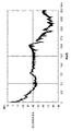
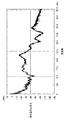
しかし、含浸を行ったトランスでは、トランスごとに発生する唸り音の大きさにばらつきが生じる。図8は、唸り音の静かなトランスにおける唸り音の音響スペクトルを示した図である。図9は、唸り音の大きなトランスにおける唸り音の音響スペクトルを示した図である。横軸は周波数を示し、縦軸は唸り音の大きさを示している。中央磁脚まで含浸剤が到達していれば、対向する中央磁脚同士が強く接着される。このようなトランスでは、唸り音は小さくなる。一方、中央磁脚まで含浸剤が到達していないトランスでは唸り音が大きくなる。 However, in the transformer that has been impregnated, variation occurs in the level of the roaring sound generated for each transformer. FIG. 8 is a diagram showing an acoustic spectrum of a roaring sound in a transformer with a quiet roaring sound. FIG. 9 is a diagram showing an acoustic spectrum of a roaring sound in a transformer with a loud roaring sound. The horizontal axis indicates the frequency, and the vertical axis indicates the loud sound. If the impregnating agent reaches the central magnetic legs, the opposing central magnetic legs are strongly bonded to each other. With such a transformer, the roaring sound is reduced. On the other hand, in the transformer in which the impregnating agent has not reached the central magnetic leg, the roaring noise is increased.
図10は、外側磁脚同士が接着されていないトランスに発生する唸り音の発生メカニズムを説明するための図である。第1のフェライトコア101が備える第1の外側磁脚116aと、第2のフェライトコア102が備える第1の外側磁脚116bとが擦り合うため、大きな唸り音が発生する。同様に、第1のフェライトコア101が備える第2の外側磁脚117aと、第2のフェライトコア102が備える第1の外側磁脚117bとが擦り合うため、大きな唸り音が発生する。なお、第1のフェライトコア101が備える中央磁脚118aと、第2のフェライトコア102が備える中央磁脚118bとの間にはギャップがあるため、擦り合いは発生しない。
FIG. 10 is a diagram for explaining a mechanism for generating a roaring sound generated in a transformer in which the outer magnetic legs are not bonded to each other. Since the first outer
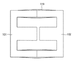
よって、対向する第1の外側磁脚116aと第1の外側磁脚116bとを接着するとともに、対向する第2の外側磁脚117aと第2の外側磁脚117bとを接着すれば、擦りを抑制できるため、唸り音が軽減される。図11、図12は、外側磁脚の固有振動を示した図である。対向する2つの外側磁脚を接着すれば唸り音が軽減され、外側磁脚の固有振動119が残るようになる。
Therefore, if the first outer
以上述べたように唸り音を抑えるためには以下の特徴が必要となる。
特徴(1)・・・対向する中央磁脚同士を接着して振動の発生を抑える。
特徴(2)・・・外側磁脚同士を接着等により一体化して磁脚同士の擦り合いによる音の発生を抑える。
特徴(3)・・・外側磁脚の固有振動を抑える。
また、以下のようなトランスの品質を達成する必要もある。
特徴(4)・・・フェライトコアとコイルボビンとの熱膨張係数の差によるコア割れの懸念が小さい。
As described above, the following features are required to suppress the roaring sound.
Feature (1): The occurrence of vibration is suppressed by bonding the opposing central magnetic legs together.
Feature (2): The outer magnetic legs are integrated with each other by bonding or the like to suppress the generation of sound due to friction between the magnetic legs.
Feature (3): Suppresses the natural vibration of the outer magnetic leg.
It is also necessary to achieve the following transformer quality.
Feature (4): There is little concern about core cracking due to the difference in thermal expansion coefficient between the ferrite core and the coil bobbin.
しかし、特許文献1に記載の接着技術では、特徴(3)及び(4)に関して課題が残る。特許文献2に記載の接着及び含浸技術では、特徴(3)に関して課題が残る。さらに、特許文献3に記載の弾性シートでは、コア同士の振動を抑制することはできないため、特徴(1)、(2)、(3)に関して課題が残る。 However, in the bonding technique described in Patent Document 1, problems remain regarding the features (3) and (4). In the adhesion and impregnation technique described in Patent Document 2, a problem remains regarding the feature (3). Furthermore, since the elastic sheet described in Patent Document 3 cannot suppress vibrations between the cores, problems remain regarding the features (1), (2), and (3).
ところで、昨今の各種電気機器では、消費電力の低い省エネルギー型の機器が望まれている。例えば、電源装置内のIC等も省エネルギーに対応するため、軽負荷運転時に電装置源のスイッチング回数を減らして効率向上を図る機器が増えてきた。この結果、電源装置が備えるトランスの駆動周波数が可聴周波数域となる場合がある。また、電子機器が軽負荷運転しているときは動作音が静かになる。そのため、かえってトランスの唸り音がより顕著に聞こえるようになる。このような理由から、外側磁脚の固有振動に起因したトランスの唸り音を低減することが必須となりつつある。 By the way, in recent various electric devices, energy-saving devices with low power consumption are desired. For example, in order to cope with energy saving, the IC in the power supply apparatus has increased the number of devices that improve the efficiency by reducing the number of switching of the power source during light load operation. As a result, the drive frequency of the transformer included in the power supply apparatus may be in the audible frequency range. Also, when the electronic device is operating at a light load, the operation sound is quiet. Therefore, the roaring sound of the transformer can be heard more prominently. For these reasons, it is becoming essential to reduce the ringing noise of the transformer due to the natural vibration of the outer magnetic legs.
そこで、本発明は、このような課題および他の課題のうち、少なくとも1つを解決することを目的とする。本発明は、例えば、コア割れの懸念を小さくしつつ、外側磁脚の固有振動に起因したトランスの唸り音を軽減することを目的とする。なお、他の課題については明細書の全体を通して理解できよう。 Therefore, an object of the present invention is to solve at least one of such problems and other problems. An object of the present invention is, for example, to reduce the noise of a transformer caused by the natural vibration of an outer magnetic leg while reducing the fear of core breakage. Other issues can be understood throughout the specification.
本発明のトランスは、例えば、スイッチング電源装置やDC−DCコンバータ装置に採用できる。トランスは、第1コア、第2コア、第1接着部、第2接着部、ボビン及び弾性部材を備える。第1コアおよび第2コアは、中央磁脚と、中央磁脚よりも外側に位置する外側磁脚とを有する。第1接着部は、第1コアの中央磁脚と第2コアの中央磁脚とを接着する。第2接着部は、第1コアの外側磁脚と第2コアの外側磁脚とを接着する。ボビンは、第1コアの中央磁脚と第2コアの中央磁脚とに通され、一次巻線及び二次巻線を巻回される。とりわけ、弾性部材は、第2接着部の付近における第1コアの外側磁脚と第2コアの外側磁脚とをトランスの内部に向かう方向へ押圧する。 The transformer of the present invention can be employed in, for example, a switching power supply device and a DC-DC converter device. The transformer includes a first core, a second core, a first adhesive portion, a second adhesive portion, a bobbin, and an elastic member. The first core and the second core have a central magnetic leg and an outer magnetic leg located outside the central magnetic leg. The first bonding portion bonds the central magnetic leg of the first core and the central magnetic leg of the second core. The second bonding portion bonds the outer magnetic leg of the first core and the outer magnetic leg of the second core. The bobbin is passed through the central magnetic leg of the first core and the central magnetic leg of the second core, and the primary winding and the secondary winding are wound around the bobbin. In particular, the elastic member presses the outer magnetic leg of the first core and the outer magnetic leg of the second core in the vicinity of the second adhesive portion in a direction toward the inside of the transformer.
本発明によれば、コア割れの懸念を小さくしつつ、外側磁脚の固有振動に起因したトランスの唸り音を軽減することができる。また、本発明のトランスをスイッチング電源装置やDC−DCコンバータ装置に採用することで、スイッチング電源装置やDC−DCコンバータ装置を低周波で運転することが可能となり、電源効率が改善する。 According to the present invention, it is possible to reduce the noise of the transformer caused by the natural vibration of the outer magnetic leg while reducing the concern about the core crack. Further, by adopting the transformer of the present invention for a switching power supply device or a DC-DC converter device, the switching power supply device or the DC-DC converter device can be operated at a low frequency, and the power supply efficiency is improved.
以下に本発明の一実施形態を示す。以下で説明される個別の実施形態は、本発明の上位概念、中位概念および下位概念など種々の概念を理解するために役立つであろう。また、本発明の技術的範囲は、特許請求の範囲によって確定されるのであって、以下の個別の実施形態によって限定されるわけではない。 An embodiment of the present invention is shown below. The individual embodiments described below will help to understand various concepts, such as the superordinate concept, intermediate concept and subordinate concept of the present invention. Further, the technical scope of the present invention is determined by the scope of the claims, and is not limited by the following individual embodiments.
[実施例1]
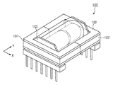
図1は、実施例1に係るEE型のトランス130を示した斜視図である。トランス130は、例えば、スイッチング電源装置やDC−DCコンバータ装置などで利用される。水平断面がE字型をした第1のフェライトコア101は、第1の外側磁脚116a、第2の外側磁脚117a、中央磁脚118aを有している。同様に、第2のフェライトコア102は、第1の外側磁脚116b、第2の外側磁脚117b、中央磁脚118bを有している。第1のフェライトコア101は第1コアの一例であり、第2のフェライトコア102は第2コアの一例である。
[Example 1]
FIG. 1 is a perspective view illustrating an
コイルボビン103は、一次巻線および二次巻線が巻回されている。コイルボビン103の軸は空洞となっており、この空洞に中央磁脚118a、118bが挿通される。水平方向は、図1に示されたX軸とY軸とを含む水平面と平行な方向である。なお、コイルボビン103の形状は、図1で示されるように空洞を設けた円柱形状である。なお、コイルボビン103としては円柱形状に限らず角柱形状のものにも適用可能である。
The
とりわけ、実施例1では、中央磁脚118aの突合せ面と中央磁脚118bの突合せ面とが接着剤108により接着されている。すなわち、接着剤108により、第1接着部が形成されている。接着剤108としては、一液や二液式のエポキシ系接着剤のような接着後の硬度がショアD硬度で70程度と高いものが良い。ショアD硬度で40程度と硬度が低いものでは唸り音に対しての効果が少ない。
In particular, in Example 1, the butting surface of the center
第1のフェライトコア101が備える第1の外側磁脚116aと第2のフェライトコア102が備える第1の外側磁脚116bとが接着剤109によって接着されている。同様に、第2の外側磁脚117aと第2の外側磁脚117bとも接着剤109によって接着されている。すなわち、接着剤109により、第2接着部が形成されている。なお、外側磁脚の突合せ面同士を接着するための接着剤109としては、硬化前の粘度が低いものが良い。硬化前の粘度が高い接着剤であると外側磁脚間のギャップが、例えば、10μm以上になり、リーケージインダクタンス(漏れインダクタンス)が増加してしまう。さらに、ギャップが10μm以上であると、トランスのインダクタンス値(L値)が低下してしまう。従って、本実施例では、硬化前の粘度が低く、かつ硬化後の高度硬度が高い接着剤を用いた。なお、選択するトランスの構成や仕様によっては、接着剤として硬化前の粘度が高いものを用いることも可能である。
A first outer
熱収縮チューブ110は、第2接着部の付近における第1コアの外側磁脚と第2コアの外側磁脚とをトランスの内部に向かう方向へ押圧する弾性部材の一例である。この熱収縮チューブ110としては難燃性のものを使用するのが良い。熱収縮チューブ110としては、例えば、電子線架橋ポリオレフィンやシリコンゴムを素材とした熱収縮チューブを採用できる。
The heat-
図1が示すように、熱収縮チューブ110の巻架位置は、第1のフェライトコア101と第2のフェライトコア102との突合せ面を覆うような位置である。また、熱収縮チューブ110は、中央磁脚の軸方向に対して直交する方向に巻架されている。
As shown in FIG. 1, the winding position of the heat-
熱収縮チューブ110は、環状の弾性部材であり、熱を加えることで内周(内径)が収縮する。熱収縮前における熱収縮チューブ110の内周(内径)は中央磁脚と直交する方向におけるトランスの外径(外径)よりも大きく、熱収縮後の内周(内径)は中央磁脚と直交する方向におけるトランスの外径(外径)よりも小さくなければならない。これは、熱収縮チューブ110の引っ張り応力によって、外側磁脚の突合せ面に界面圧力を残存させるためである。
The heat-
<トランスの唸り音の発生メカニズム>
トランス130の巻線に電流を流してトランス130を励磁すると、巻線により磁界が発生する。この磁界により各コアには対向するコアを吸い付ける方向の電磁力が発生する。電磁力により各コアは微小ながら弾性変形する。さらに磁界によるコア材料の磁歪によっても弾性変形する。電磁力及び磁歪力は磁束密度が高いところで大きく発生する。そのため、コアの中でも中央磁脚がもっとも大きな力を受ける。そしてコアの変位量は中央磁脚がもっとも大きくなる。磁界が発生しなくなると復元力が働き、コアはもとの形に戻ろうとする。
<Generation mechanism of transformer noise>
When current is passed through the winding of the
このように発生した振動がコア自身を弾性変形させながら外側磁脚に伝達される。外足磁脚が接着されていないと外側磁脚同士が擦れ合うことにより、音が発生する。外側磁脚を接着すると外側磁脚は固有振動数を有するようになる。この固有振動数は外側磁脚の接着状態によって異なってくると同時に、固有振動数での振動は外側磁脚同士の接着だけでは抑制できない。 The vibration generated in this way is transmitted to the outer magnetic leg while elastically deforming the core itself. If the outer leg magnetic legs are not bonded, the outer magnetic legs rub against each other to generate sound. When the outer magnetic legs are bonded, the outer magnetic legs have a natural frequency. The natural frequency varies depending on the bonding state of the outer magnetic legs, and at the same time, vibration at the natural frequency cannot be suppressed only by bonding the outer magnetic legs.
そこで、本実施例では、熱収縮チューブ110をトランス130に被せることにより外側磁脚の固有振動を抑えている。熱収縮チューブ110がもたらす引っ張り応力が、外側磁脚の突合せ面に界面圧力を残存させる。図2は、実施例1に係るトランス130で発生する唸り音の周波数スペクトルを示した図である。図2が示すように、実施例1によれば、唸り音を6dBm程度へと低減することが可能となる。
Therefore, in this embodiment, the natural contraction of the outer magnetic leg is suppressed by covering the
さらに、熱収縮チューブ110を用いれば、コイルボビン103、第1のフェライトコア101及び第2のフェライトコア102を弾性材で固定したことになる。そのため、仮に中央磁脚での接着剤108があふれてコイルボビン103に付着したとしてもコアとコイルボビンを強固に接着した箇所は1箇所だけとなる。よって、コアが割れる懸念が極めて小さくなる。従って、中央磁脚の接着剤108の量も厳密に規定する必要がなくなり、作業性も向上する。
Furthermore, if the heat
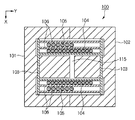
図3は、実施例1に係るEE型のトランスの水平方向における断面図である。第1のフェライトコア101の中央磁脚118aと、第2のフェライトコア102の中央磁脚118bとの間にはギャップ115が設けられている。上述したようにギャップ115には接着剤108が充填される。コイルボビン103には、一次巻線104と二次巻線105とが層間紙106を挟むようにして巻回されている。
FIG. 3 is a cross-sectional view in the horizontal direction of the EE type transformer according to the first embodiment. A
図3によれば、コイルボビン103、一次巻線104及び二次巻線105により形成されたコイルと、外側磁脚との間に弾性材301が嵌挿されている。すなわち、外側磁脚の接着部とコイルとの間に弾性材301が挟まれている。熱収縮チューブ110がトランス130の外側方向への外側磁脚の固有振動を抑制し、弾性材301がトランス130の内側方向への外側磁脚の固有振動を抑制する。熱収縮チューブ110と弾性材301とによって、さらに唸り音を軽減する効果が高くなる。
According to FIG. 3, the
実施例1によれば、第2接着部の付近における第1のフェライトコア101の外側磁脚と第2のフェライトコア102の外側磁脚とをトランス130の内部に向かう方向へ押圧する熱収縮チューブ110を採用する。これにより、外側磁脚の固有振動が抑制され、唸り音が軽減される。
According to the first embodiment, the heat-shrinkable tube that presses the outer magnetic leg of the
スイッチング電源装置やDC−DCコンバータは、軽負荷で運転されているときにスイッチング回数を低減する。外側磁脚の固有振動に起因したトランスの唸り音は、スイッチング電源装置やDC−DCコンバータが軽負荷で運転しているときに顕著となりやすい。しかし、本実施例のトランス130をスイッチング電源装置やDC−DCコンバータ装置に採用することで唸り音が軽減されるため、スイッチング電源装置やDC−DCコンバータ装置を低周波で運転することが可能となる。低周波運転により、電源効率が改善する。
Switching power supply devices and DC-DC converters reduce the number of times of switching when they are operated with light loads. The roaring sound of the transformer due to the natural vibration of the outer magnetic leg is likely to be noticeable when the switching power supply device or the DC-DC converter is operated with a light load. However, the use of the
なお、本例では、伸縮性のチューブを適用したが、例えば、伸縮性のテープなどを使用しても同様の効果を得ることができる。 In this example, the stretchable tube is applied, but the same effect can be obtained even when a stretchable tape or the like is used.
[実施例2]
第1のフェライトコア101の外側磁脚と第2のフェライトコア102の外側磁脚とを押圧する弾性部材として、実施例1では熱収縮チューブ110を用いた。実施例2では、弾性部材として、伸縮性チューブを用いる。熱収縮チューブ110は加熱することで収縮するが、伸縮性チューブでは加熱工程が不要となる。そのため、製造工程のが簡素化される。
[Example 2]
In Example 1, the heat
図4は、実施例2に係るEE型のトランス400を示した斜視図である。熱収縮チューブ110に代えて、伸縮性チューブ410が採用されている。伸縮性チューブ410としては、シリコンゴムなど、耐高温度、耐ヒートサイクル、引き裂き、難燃性に関して優れた素材からなるチューブが採用されるべきであろう。
FIG. 4 is a perspective view illustrating an
実施例2によれば、実施例1と同様の効果に加え、製造工程の簡素化といった効果も奏される。なお、実施例1と同様に、コイルボビン103、一次巻線104及び二次巻線105により形成されたコイルと、外側磁脚との間に弾性材301が嵌挿されてもよい。伸縮性チューブ410と弾性材301とによって、さらに唸り音が軽減されよう。
According to the second embodiment, in addition to the same effects as those of the first embodiment, effects such as simplification of the manufacturing process can be achieved. As in the first embodiment, the
[実施例3]
第1のフェライトコア101の外側磁脚と第2のフェライトコア102の外側磁脚とを押圧する弾性部材として、実施例1では熱収縮チューブ110を、実施例2では伸縮性チューブ410を採用した。実施例3では、バネ性部材を採用する。
[Example 3]
As an elastic member that presses the outer magnetic leg of the
図5は、実施例3に係るEE型のトランス500を示した斜視図である。本実施例では、熱収縮チューブ110や伸縮性チューブ410に代えて、バネ性部材510が採用されている。バネ性部材510も、第1のフェライトコア101の外側磁脚と第2のフェライトコア102の外側磁脚とを、外側磁脚から中央磁脚へと向かう方向へ押圧する。よって、外側磁脚の突合せ面に界面圧力が作用する。
FIG. 5 is a perspective view illustrating an
実施例3によれば、実施例1と同様の効果が奏される。なお、実施例1や2と同様に、コイルボビン103、一次巻線104及び二次巻線105により形成されたコイルと、外側磁脚との間に弾性材301が嵌挿されてもよい。バネ性部材510と弾性材301とによって、さらに唸り音が軽減されよう。
According to the third embodiment, the same effect as that of the first embodiment is achieved. As in the first and second embodiments, the
なお、上述の実施例1乃至3では、横置き型のトランスを一例として説明したが、縦置き型のトランスにおいても適用可能である。 In the first to third embodiments, the horizontal type transformer has been described as an example, but the present invention can also be applied to a vertical type transformer.
101‥‥第1のフェライトコア
102‥‥第2のフェライトコア
103‥‥コイルボビン
104‥‥一次巻線
105‥‥二次巻線
106‥‥層間紙
110‥‥熱収縮チューブ
108‥‥中央磁脚を接着する接着剤
109‥‥外側磁脚を接着する接着剤
DESCRIPTION OF
Claims (7)
中央磁脚と、該中央磁脚よりも外側に位置する外側磁脚とをそれぞれ有する第1コアおよび第2コアと、
前記第1コアの中央磁脚と前記第2コアの中央磁脚とを接着する第1接着部と、
前記第1コアの外側磁脚と前記第2コアの外側磁脚とを接着する第2接着部と、
前記第1コアの中央磁脚と前記第2コアの中央磁脚とに通され、一次巻線及び二次巻線を巻回されたボビンと、
前記第2接着部の付近における前記第1コアの外側磁脚と前記第2コアの外側磁脚とを前記トランスの内部に向かう方向へ押圧する弾性部材と
を備えることを特徴とするトランス。 A transformer,
A first magnetic core and a second core each having a central magnetic leg and an outer magnetic leg located outside the central magnetic leg;
A first bonding portion for bonding the central magnetic leg of the first core and the central magnetic leg of the second core;
A second bonding portion for bonding the outer magnetic leg of the first core and the outer magnetic leg of the second core;
A bobbin passed through a central magnetic leg of the first core and a central magnetic leg of the second core and wound with a primary winding and a secondary winding;
A transformer comprising: an elastic member that presses the outer magnetic leg of the first core and the outer magnetic leg of the second core in the vicinity of the second adhesive portion in a direction toward the inside of the transformer.
熱収縮前の内径が、前記中央磁脚と直交する方向における前記トランスの外径よりも大きく、
熱収縮後の内径が、前記トランスの外径よりも小さい熱収縮チューブである
ことを特徴とする請求項1に記載のトランス。 The elastic member is
The inner diameter before heat shrinkage is larger than the outer diameter of the transformer in the direction orthogonal to the central magnetic leg,
The transformer according to claim 1, wherein the inner diameter after heat shrinkage is a heat shrinkable tube smaller than the outer diameter of the transformer.
請求項1ないし5のいずれか1項に記載のトランスを備えたことを特徴とするスイッチング電源装置。 A switching power supply,
A switching power supply device comprising the transformer according to claim 1.
請求項1ないし5のいずれか1項に記載のトランスを備えたことを特徴とするDC−DCコンバータ装置。 A DC-DC converter device,
A DC-DC converter device comprising the transformer according to claim 1.
Priority Applications (2)
| Application Number | Priority Date | Filing Date | Title |
|---|---|---|---|
| JP2009006897A JP2010165857A (en) | 2009-01-15 | 2009-01-15 | Transformer, switching power supply device, and dc-dc converter device |
| US12/684,078 US8242873B2 (en) | 2009-01-15 | 2010-01-07 | Transformer, switching power supply device, and DC-DC converter device |
Applications Claiming Priority (1)
| Application Number | Priority Date | Filing Date | Title |
|---|---|---|---|
| JP2009006897A JP2010165857A (en) | 2009-01-15 | 2009-01-15 | Transformer, switching power supply device, and dc-dc converter device |
Publications (2)
| Publication Number | Publication Date |
|---|---|
| JP2010165857A true JP2010165857A (en) | 2010-07-29 |
| JP2010165857A5 JP2010165857A5 (en) | 2012-03-01 |
Family
ID=42318637
Family Applications (1)
| Application Number | Title | Priority Date | Filing Date |
|---|---|---|---|
| JP2009006897A Pending JP2010165857A (en) | 2009-01-15 | 2009-01-15 | Transformer, switching power supply device, and dc-dc converter device |
Country Status (2)
| Country | Link |
|---|---|
| US (1) | US8242873B2 (en) |
| JP (1) | JP2010165857A (en) |
Cited By (8)
| Publication number | Priority date | Publication date | Assignee | Title |
|---|---|---|---|---|
| JP2012084773A (en) * | 2010-10-14 | 2012-04-26 | Sumitomo Electric Ind Ltd | Reactor |
| WO2012176558A1 (en) * | 2011-06-21 | 2012-12-27 | 住友電気工業株式会社 | Reactor, and manufacturing method therefor |
| JP2013161897A (en) * | 2012-02-03 | 2013-08-19 | Kobe Steel Ltd | Winding element |
| JP2014123680A (en) * | 2012-12-21 | 2014-07-03 | Toyota Motor Corp | Reactor and method of manufacturing the same |
| US8933772B2 (en) | 2011-06-21 | 2015-01-13 | Minebea Co., Ltd. | Coil component |
| JP2015057029A (en) * | 2013-09-13 | 2015-03-23 | 株式会社タムラ製作所 | Module component for power supply |
| JP2017188679A (en) * | 2016-03-31 | 2017-10-12 | 太陽誘電株式会社 | Coil parts |
| US9805856B2 (en) | 2014-06-05 | 2017-10-31 | Sumida Corporation | Coil component and method of manufacturing coil component |
Families Citing this family (14)
| Publication number | Priority date | Publication date | Assignee | Title |
|---|---|---|---|---|
| JP5268615B2 (en) | 2008-12-15 | 2013-08-21 | キヤノン株式会社 | Power supply device and image forming apparatus |
| JP5489502B2 (en) * | 2009-03-19 | 2014-05-14 | キヤノン株式会社 | Power supply |
| JP5873293B2 (en) | 2011-10-31 | 2016-03-01 | キヤノン株式会社 | Power supply device and image forming apparatus |
| JP5950635B2 (en) | 2012-03-09 | 2016-07-13 | キヤノン株式会社 | Power supply device and image forming apparatus |
| DE102013101364B4 (en) * | 2013-02-12 | 2023-02-02 | Tdk Electronics Ag | Electrical transformer component |
| JP6143499B2 (en) | 2013-03-08 | 2017-06-07 | キヤノン株式会社 | Power supply device and image forming apparatus |
| JP6218446B2 (en) | 2013-06-14 | 2017-10-25 | キヤノン株式会社 | Power supply device and image forming apparatus |
| JP6300515B2 (en) | 2013-12-24 | 2018-03-28 | キヤノン株式会社 | Power supply device and image forming apparatus |
| JP6354304B2 (en) * | 2014-05-09 | 2018-07-11 | スミダコーポレーション株式会社 | Inductor and method of manufacturing inductor |
| JP6530566B2 (en) * | 2016-09-13 | 2019-06-12 | 株式会社日立製作所 | Transformer and power converter |
| KR102668598B1 (en) * | 2016-11-28 | 2024-05-24 | 삼성전기주식회사 | Wire-wound Type Power Inductor |
| CN107452489B (en) * | 2017-08-17 | 2018-12-11 | 芜湖市凯鑫避雷器有限责任公司 | A kind of universal coil structure for a variety of transformers |
| JP7166843B2 (en) | 2018-08-28 | 2022-11-08 | キヤノン株式会社 | Power supply and image forming apparatus |
| JP7175699B2 (en) | 2018-10-04 | 2022-11-21 | キヤノン株式会社 | Power supply and image forming apparatus |
Citations (5)
| Publication number | Priority date | Publication date | Assignee | Title |
|---|---|---|---|---|
| JPS6254416A (en) * | 1985-09-02 | 1987-03-10 | Nippon Ferrite Ltd | Method for fixing magnetic core |
| JPS62122318U (en) * | 1986-01-27 | 1987-08-03 | ||
| JPH0528012U (en) * | 1991-09-20 | 1993-04-09 | 株式会社村田製作所 | Inductor |
| JP2004140261A (en) * | 2002-10-18 | 2004-05-13 | Sanken Electric Co Ltd | Transformer, switching power unit and manufacturing method of transformer |
| JP2007123767A (en) * | 2005-10-31 | 2007-05-17 | Tamura Seisakusho Co Ltd | Reactor |
Family Cites Families (7)
| Publication number | Priority date | Publication date | Assignee | Title |
|---|---|---|---|---|
| GB2035706B (en) * | 1978-11-09 | 1983-05-05 | Tdk Electronics Co Ltd | Inductance element |
| US4791395A (en) * | 1986-08-14 | 1988-12-13 | American Telephone And Telegraph Company At&T Bell Laboratories | Magnetic core apparatus and method of constructing the same |
| JPH06132146A (en) | 1992-10-15 | 1994-05-13 | Matsushita Electric Ind Co Ltd | Transformer and electronic device using the same |
| JPH07192934A (en) | 1993-12-27 | 1995-07-28 | Taiyo Yuden Co Ltd | Coil component and manufacture thereof |
| JPH10270261A (en) | 1997-03-27 | 1998-10-09 | Victor Co Of Japan Ltd | Transformer device and coil device |
| JP2001135529A (en) | 1999-11-05 | 2001-05-18 | Kawaguchiko Seimitsu Co Ltd | Step-up transformer |
| JP2005057016A (en) | 2003-08-01 | 2005-03-03 | Keihin Corp | Transformer and its assembly method |
-
2009
- 2009-01-15 JP JP2009006897A patent/JP2010165857A/en active Pending
-
2010
- 2010-01-07 US US12/684,078 patent/US8242873B2/en not_active Expired - Fee Related
Patent Citations (5)
| Publication number | Priority date | Publication date | Assignee | Title |
|---|---|---|---|---|
| JPS6254416A (en) * | 1985-09-02 | 1987-03-10 | Nippon Ferrite Ltd | Method for fixing magnetic core |
| JPS62122318U (en) * | 1986-01-27 | 1987-08-03 | ||
| JPH0528012U (en) * | 1991-09-20 | 1993-04-09 | 株式会社村田製作所 | Inductor |
| JP2004140261A (en) * | 2002-10-18 | 2004-05-13 | Sanken Electric Co Ltd | Transformer, switching power unit and manufacturing method of transformer |
| JP2007123767A (en) * | 2005-10-31 | 2007-05-17 | Tamura Seisakusho Co Ltd | Reactor |
Cited By (10)
| Publication number | Priority date | Publication date | Assignee | Title |
|---|---|---|---|---|
| JP2012084773A (en) * | 2010-10-14 | 2012-04-26 | Sumitomo Electric Ind Ltd | Reactor |
| WO2012176558A1 (en) * | 2011-06-21 | 2012-12-27 | 住友電気工業株式会社 | Reactor, and manufacturing method therefor |
| JP2013004932A (en) * | 2011-06-21 | 2013-01-07 | Sumitomo Electric Ind Ltd | Reactor and method for manufacturing the same |
| US8933772B2 (en) | 2011-06-21 | 2015-01-13 | Minebea Co., Ltd. | Coil component |
| JP2013161897A (en) * | 2012-02-03 | 2013-08-19 | Kobe Steel Ltd | Winding element |
| JP2014123680A (en) * | 2012-12-21 | 2014-07-03 | Toyota Motor Corp | Reactor and method of manufacturing the same |
| US9679694B2 (en) | 2012-12-21 | 2017-06-13 | Toyota Jidosha Kabushiki Kaisha | Manufacturing method of a reactor |
| JP2015057029A (en) * | 2013-09-13 | 2015-03-23 | 株式会社タムラ製作所 | Module component for power supply |
| US9805856B2 (en) | 2014-06-05 | 2017-10-31 | Sumida Corporation | Coil component and method of manufacturing coil component |
| JP2017188679A (en) * | 2016-03-31 | 2017-10-12 | 太陽誘電株式会社 | Coil parts |
Also Published As
| Publication number | Publication date |
|---|---|
| US8242873B2 (en) | 2012-08-14 |
| US20100176907A1 (en) | 2010-07-15 |
Similar Documents
| Publication | Publication Date | Title |
|---|---|---|
| JP2010165857A (en) | Transformer, switching power supply device, and dc-dc converter device | |
| JP5197220B2 (en) | Reactor manufacturing method | |
| JP2013004887A (en) | Coil component | |
| US20140176291A1 (en) | Choke coil | |
| JP2008028290A (en) | Reactor device and assembly method thereof | |
| JP2010165857A5 (en) | ||
| TWM517900U (en) | Structure of transformer | |
| JP5310460B2 (en) | Manufacturing method of laminated core | |
| JP4947426B2 (en) | Pulse transformer | |
| JP6242160B2 (en) | Dynamic headphone unit and method for manufacturing dynamic headphone unit | |
| JP2011023561A (en) | Braided wire toroidal coil and manufacturing method thereof | |
| WO2017085797A1 (en) | Iron core joint structure of stationary induction electric device, and method of joining iron core | |
| JP2017216390A (en) | Wound core and manufacturing method of the same | |
| JP6318083B2 (en) | Winding iron core for static induction | |
| JP2005310988A (en) | Method for assembling reactor or transformer | |
| KR101456525B1 (en) | Bidirectional high frequency transformer | |
| JP2004273471A (en) | Component with core and its manufacturing method | |
| KR20060089602A (en) | Reactor | |
| JP2009111316A (en) | Reactor | |
| JP2011129834A (en) | Resin mold transformer, and method of manufacturing the same | |
| KR100340419B1 (en) | Ferrite core of fbt | |
| JP6578157B2 (en) | Resin mold core, reactor | |
| JP7402761B2 (en) | Manufacturing method of stator of rotating electric machine | |
| JP2017183442A (en) | Amorphous Transformer | |
| KR200247670Y1 (en) | A structure of iron core |
Legal Events
| Date | Code | Title | Description |
|---|---|---|---|
| A521 | Request for written amendment filed |
Free format text: JAPANESE INTERMEDIATE CODE: A523 Effective date: 20120112 |
|
| A621 | Written request for application examination |
Free format text: JAPANESE INTERMEDIATE CODE: A621 Effective date: 20120112 |
|
| A977 | Report on retrieval |
Free format text: JAPANESE INTERMEDIATE CODE: A971007 Effective date: 20121228 |
|
| A131 | Notification of reasons for refusal |
Free format text: JAPANESE INTERMEDIATE CODE: A131 Effective date: 20130108 |
|
| A521 | Request for written amendment filed |
Free format text: JAPANESE INTERMEDIATE CODE: A523 Effective date: 20130311 |
|
| A02 | Decision of refusal |
Free format text: JAPANESE INTERMEDIATE CODE: A02 Effective date: 20130719 |