JP2010155331A - Vacuum-type suction device and robot hand - Google Patents
Vacuum-type suction device and robot hand Download PDFInfo
- Publication number
- JP2010155331A JP2010155331A JP2009000255A JP2009000255A JP2010155331A JP 2010155331 A JP2010155331 A JP 2010155331A JP 2009000255 A JP2009000255 A JP 2009000255A JP 2009000255 A JP2009000255 A JP 2009000255A JP 2010155331 A JP2010155331 A JP 2010155331A
- Authority
- JP
- Japan
- Prior art keywords
- piston
- cylinder tube
- space
- open end
- vacuum cup
- Prior art date
- Legal status (The legal status is an assumption and is not a legal conclusion. Google has not performed a legal analysis and makes no representation as to the accuracy of the status listed.)
- Granted
Links
Images


Abstract
Description
本発明は、例えば各種の生産ラインにおいてワークを吸着支持するためのバキューム式吸着装置とその吸着装置を用いたロボットハンドに関する。 The present invention relates to a vacuum suction device for sucking and supporting a workpiece in various production lines, for example, and a robot hand using the suction device.
例えばパネル状のワークに対してその面直角方向からバキュームカップ(バキュームパッド)を有するロボットハンドをアプローチ動作させて、当該ワークを吸着支持した上で所定位置まで搬送するにあたり、ワーク全体形状としては比較的フラットな形状ではあっても、バキュームカップにて吸着支持したときの重量バランス等の関係から、当該ワークのうちでも特定部位の傾斜した部位を吸着支持しなければならないことがある。 For example, when a robot hand with a vacuum cup (vacuum pad) is approached from a direction perpendicular to the surface of a panel-shaped workpiece, the workpiece is sucked and supported, and then transferred to a predetermined position. Even if the shape is flat, it may be necessary to suck and support a specific portion of the workpiece that is inclined due to the weight balance when sucking and supporting the vacuum cup.
このような場合には、ワーク側の傾斜した部位とバキュームカップ側の吸着面とが平行となるように予め設定しておき、ワークに対するロボットハンドそのもののアプローチ方向は傾斜した部位に関係なく先に述べた方向からそのワークを吸着支持するようにしている。 In such a case, it is set in advance so that the inclined part on the workpiece side and the suction surface on the vacuum cup side are parallel to each other, and the approach direction of the robot hand itself to the workpiece is the first regardless of the inclined part. The workpiece is supported by suction from the stated direction.
また、このようなワークの吸着支持に適したバキューム式吸着装置として特許文献1,2に記載のものが提案されている。これらの特許文献1,2に記載のものでは、バキュームカップが単独でストローク動作可能となっていて、バキュームカップによるワークの吸着と同時に所定量だけワークをリフトアップさせる機能を有している。
しかしながら、上記のようなワークの吸着支持形態では、ワーク側の傾斜した部位とバキュームカップ側の吸着面とが平行となるように予め設定しておくものの、ワークに対するロボットハンドそのもののアプローチ方向は先に述べた方向からのものとなる。そのため、ワーク側の吸着すべき部位、すなわちワーク側の傾斜した部位に対するバキュームカップのアプローチ方向は当該傾斜した部位に対しては面直方向からのものとはならず、その傾斜した部位に対して鋭角な方向からのアプローチ動作となる。その結果、バキュームカップのアプローチ軌跡の影響でバキュームカップの端部にめくれ現象が発生し、吸着ミスが発生するおそれがある。 However, in the workpiece suction support mode as described above, although the inclined portion on the workpiece side and the suction surface on the vacuum cup side are set in advance, the approach direction of the robot hand itself to the workpiece is first. From the direction described in. Therefore, the approach direction of the vacuum cup with respect to the part to be adsorbed on the workpiece side, that is, the inclined part on the workpiece side is not from the direction perpendicular to the inclined part. Approach action from an acute angle. As a result, a turn-up phenomenon occurs at the end of the vacuum cup due to the influence of the approach locus of the vacuum cup, and there is a possibility that a suction error will occur.
また、バキュームカップで吸着可能なワーク側の傾斜した部位の角度はワークの一般面に対する角度で40°程度が限界とされ、傾斜角度がそれ以上大きくなるとバキュームカップによる吸着方式に代えてクランプあるいはジョーと称されるいわゆる掴み型のハンドを採用する必要がある。この場合には、バキュームカップによる吸着方式と比べてワークの把持から搬送までに要する時間が長くなり、搬送スピードの低下をもたらす結果となって好ましくない。 In addition, the angle of the inclined part on the workpiece side that can be attracted by the vacuum cup is limited to about 40 ° with respect to the general surface of the workpiece, and if the inclination angle becomes larger than that, the suction method using the vacuum cup is replaced with a clamp or jaw. It is necessary to adopt a so-called grip-type hand. In this case, as compared with the suction method using a vacuum cup, the time required from gripping the workpiece to conveyance becomes longer, which is not preferable because the conveyance speed is lowered.
本発明はこのような課題に着目してなされたものであり、先にも述べたように相手側部材の傾斜した部位をバキュームカップで吸着しなければならない場合であっても、めくれ現象による吸着ミスが発生することがなく、より確実に相手側部材を吸着することができるようにしたバキューム式吸着装置とロボットハンドを提供するものである。 The present invention has been made paying attention to such a problem, and as described above, even when the inclined portion of the counterpart member has to be adsorbed by a vacuum cup, the adsorbed by the turning-up phenomenon The present invention provides a vacuum suction device and a robot hand that are capable of attracting a counterpart member more reliably without causing a mistake.
本発明では、所期の目的を達成するために、例えば相手側部材の傾斜した部位をバキュームカップで吸着しなければならない場合であっても、ストローク動作が可能なバキュームカップを相手側部材の吸着すべき部位に対してその面直角方向からアプローチ動作させて吸着する構造としてある。 In the present invention, in order to achieve the intended purpose, for example, even when the inclined portion of the mating member must be sucked by the vacuum cup, the vacuum cup capable of stroke operation is sucked by the mating member. The structure is such that the portion to be attracted is approached from the direction perpendicular to the surface to be attracted.
本発明によれば、例えば相手側部材の傾斜した部位をバキュームカップで吸着しなければならない場合であっても、その吸着すべき部位に対してその面直角方向からバキュームカップをアプローチ動作させるため、バキュームカップのめくれ現象やそれに伴う吸着ミスが発生することがなく、信頼性が高くなる。 According to the present invention, for example, even when the inclined part of the counterpart member has to be adsorbed by a vacuum cup, the vacuum cup approaches the part to be adsorbed from the direction perpendicular to the surface, There is no occurrence of a vacuum cup turning-up phenomenon and a suction error associated therewith, resulting in high reliability.
また、部品点数も少ないために装置全体の構造を簡素化できるほか、負圧導入以外の別の空気圧系統の制御も不要であるため、制御の簡素化も併せて達成できる。 In addition, since the number of parts is small, the structure of the entire apparatus can be simplified, and control of another pneumatic system other than the introduction of negative pressure is unnecessary, so that simplification of control can be achieved.
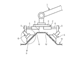
図1〜4は本発明のより具体的な実施の形態を示し、特に図1はバキュームカップ方式のロボットハンド(以下、単に「ハンド」と言う。)2についてその全体の概略構成を示している。 1 to 4 show a more specific embodiment of the present invention. In particular, FIG. 1 shows an overall schematic configuration of a vacuum cup type robot hand (hereinafter simply referred to as “hand”) 2. .
本実施の形態では、図1に示すように、相手側部材としてのパネル状のワークWに例えば長手方向(図1では紙面と直交方向)に沿ってエンボス部Eが形成されている場合であって、そのエンボス部Eの傾斜面Qを吸着すべき部位としてワークW全体を吸着支持した上で、ロボットの自律動作により搬送するものである。 In the present embodiment, as shown in FIG. 1, an embossed portion E is formed on a panel-shaped workpiece W as a counterpart member, for example, along the longitudinal direction (in FIG. 1, the direction orthogonal to the paper surface). Then, the entire workpiece W is sucked and supported by using the inclined surface Q of the embossed portion E as a portion to be sucked, and then conveyed by the autonomous operation of the robot.
搬送母機として機能する産業用ロボットのロボットアーム1の先端にハンド2を装着してある。また、ハンド2は、ロボットアーム1に支持された支持体として共通のフレーム3にエクステンションブラケット4,5等を介して複数のバキューム式吸着装置6を装着したものである。ここでは、左右対称となるように配置した一対のバキューム式吸着装置6を一組として、ワークWの長手方向(図1では紙面と直交方向)に沿って複数組のバキューム式吸着装置6を並設してある。
A
図2はバキューム式吸着装置6単独での詳細を示しており、後述するように特殊構造のエアシリンダ7とゴム等の可撓性部材からなるバキュームカップ11とを組み合わせたものと理解することができる。
FIG. 2 shows details of the
同図(A)に示すように、エアシリンダ7のシリンダチューブ8は一端が開放された円筒状のもので、内部には摺動可能なピストン9とそのピストン9に一体的に連結されたピストンロッド10が同心状に内挿されるかたちで収容配置されているとともに、ピストンロッド10はシリンダチューブ8から突出している。シリンダチューブ8とピストン9およびピストンロッド10の三者によってシリンダ7を形成していて、上記ピストン9があることによって、シリンダチューブ8の内部は開放端側の空間R1と反開放端側の空間R2とに仕切られている。なお、図2では図示省略しているが、シリンダチューブ8に対するピストン9側の摺動部にOリング等のシール部材が介装される。
As shown in FIG. 1A, the
また、シリンダチューブ8の開放側の一端には円環状のバキュームカップ11が外挿されるかたちで装着され、例えばシリンダチューブ8の開放端に螺合されるリング状のリテーナ12にて締結固定してある。そして、図1に示すように、ピストンロッド10を固定側としてバキューム式吸着装置6全体がエクステンションブラケット4,5等を介してフレーム3に固定支持されている。
Further, an
ここでは、図1,4に基づいて後述するように、いわゆる平置き状態で待機しているワークWに対してその真上の面直角方向からハンド2をアプローチ動作させて吸着支持することを前提としていることから、バキュームカップ11がワークWに接触する直前位置でハンド2全体のアプローチ動作が停止するように設定してある。そして、そのアプローチ動作の停止位置では、バキュームカップ11の先端の吸着面11aがワークW側の傾斜面Qと平行となるように、バキューム式吸着装置6の軸心を傾けてエクステンションブラケット4,5等を介してフレーム3に固定してある。
Here, as will be described later with reference to FIGS. 1 and 4, it is assumed that the
図2の(A)に示したピストンロッド10にはその長手方向に沿って負圧通路13を形成してある。この負圧通路13はピストン9側に近いポート13aを介して非開放端側の空間R2に常時連通しているとともに、負圧通路13の他端は図示しない負圧供給源に接続してある。なお、上記負圧通路13は必ずしもピストンロッド10に形成する必要はなく、要はシリンダチューブ8内の反開口端側の空間R2に負圧を導入できるようになっていれば良い。例えば、負圧通路13をピストンロッド10に形成するのに代えて、ホース等を用いてシリンダチューブ8内の反開口端側の空間R2に直接負圧を導入することも可能である。
A
また、図2の(A)に示したシリンダチューブ8の内周面であって且つその軸心方向の中間位置には、図3にも示すように円周方向の等分四箇所に所定深さの連通路14を形成してある。この連通路14の軸心方向での長さHはピストン9の厚みMよりも大きく設定してある(H>M)。そして、図2の(A)に示すようにピストン9が連通路14の位置と合致していない状態では、ピストン9はシリンダチューブ8の内部空間を開放端側の空間R1と反開放端側の空間R2とに隔離形成している。その一方、図2の(B)に示すように、ピストン9が連通路14の位置と合致する位置にある状態では、そのピストン9を迂回するようにしてシリンダチューブ8の内部空間である開放端側の空間R1と反開放端側の空間R2とが連通路14を介して相互に連通するようになっている。
Further, at the intermediate position in the axial direction on the inner peripheral surface of the
なお、シリンダチューブ8内の反開放端側の空間R2には圧縮コイルスプリングからなるリターンスプリング15を配置してある。また、リテーナ12の内周にはストッパ部12aを形成してあるとともに、シリンダチューブ8の内底部にはボス状のストッパ部8aを形成してあり、これらのストッパ部12a,8aによってシリンダチューブ8からのピストン9の抜け止めを施してあるとともにピストン9それ自体のストロークを規制するようにしてある。
A
このように構成されたハンド2によれば、図1に示したようにエンボス部Eを有するパネル状のワークWを吸着支持するのに際して、いわゆる平置き状態で待機しているワークWに対してその真上の面直角方向からハンド2をアプローチ動作させて吸着支持するものとする。この時点では、バキューム式吸着装置6におけるシリンダチューブ8内の反開口端側の空間R2には負圧が導入されておらず、リターンスプリング15のばね力が作用していることによってバキュームカップ11付きのシリンダチューブ8とピストン9とは図2の(A)に示す相対位置関係を維持している。この時、ピストン9の位置はストッパ部12aとの当接によって規制されている。
According to the
なお、図2の(A)のようなシリンダチューブ8とピストン9との相対位置関係を維持する手段として、上記リターンスプリング15に代えて、シリンダチューブ8内の反開口端側の空間R2に正圧の圧縮空気を導入するようにしても良い。
As a means for maintaining the relative positional relationship between the
そして、バキュームカップ11がワークW側の吸着部位である傾斜面Qに接触する直前位置、例えば図4に示すようにバキュームカップ11の先端の吸着面11aと傾斜面Qとのなす距離Cが例えば5〜10mm程度まで近付いた時点でハンド2全体のアプローチ動作を停止させるものとする。なお、上記の距離Cは、当然のことながらアプローチ動作の停止位置精度を考慮して決定される。この時点では、先に述べたようにワークW側の傾斜面Qとバキュームカップ11の吸着面11aとは非接触状態で且つ互いに平行となっている。
Then, the position C immediately before the
なお、図4では、図2に示したリテーナ12やそのストッパ部12a、およびストッパ部8a等は図示省略してある。
In FIG. 4, the
ハンド2が上記のアプローチ動作停止位置で停止し、且つワークW側の傾斜面Qとバキュームカップ11の吸着面11aとの相対位置関係が図4のようになったならば、その時点で図2の(A)および図4の負圧通路13を通してシリンダチューブ8内の反開放端側の空間R2に負圧を導入する。
If the
この反開放端側の空間R2への負圧の導入に伴い、バキュームカップ11付きのシリンダチューブ8とピストン9との相対位置関係は、図2の(A)の状態から同図の(B)の状態へと変化する。すなわち、図2の(A)において反開放端側の空間R2に負圧が導入されると、ピストン9が図1のフレーム3側に固定されているために、反開放端側の空間R2の容積を縮小するようにバキュームカップ11付きのシリンダチューブ8がピストン9およびピストンロッド10に対してリターンスプリング15のばね力に抗して図2の(A)のストロークSのもとでストローク動作(相対移動)する。このシリンダチューブ8のストローク動作は、ワークW側の傾斜面Qに対するバキュームカップ11の接近または前進動作にほかならず、結果として図2の(B)に示すようにバキュームカップ11が撓み変形しながらワークW側の傾斜面Qに押し付けられることになる。
With the introduction of the negative pressure into the space R2 on the side opposite to the open end, the relative positional relationship between the
この場合において、ピストン9が連通路14と合致するまでは、負圧は可動側であるシリンダチューブ8のみに作用し、ワークWを吸着するための吸引力としては消費されないため、バキュームカップ11をシリンダチューブ8とともに確実に所定のストロークSだけストローク動作させることが可能となる。
In this case, until the
なお、上記のストロークSは、例えばバキュームカップ11の撓み変形量等に応じて決定される。また、連通路14の位置やその数は負圧の大きさや上記ストロークS等に応じて決定される。逆に言うならば、連通路14の位置を調整することで上記のストロークSを調整することが可能である。
In addition, said stroke S is determined according to the deformation amount etc. of the
この場合において、バキュームカップ11はシリンダチューブ8とともにピストンロッド10に案内されながらワークW側の傾斜面Qに対してその面直角方向から接近または前進動作することから、従来のようにバキュームカップ11の一部にめくれ現象が発生することはない。
In this case, the
そして、上記のようにバキュームカップ11がワークW側の傾斜面Qに押し付けられる過程において、やがては図2の(B)に示すようにピストン9がシリンダチューブ8の内周の連通路14の位置と合致するようになる。なお、この時のピストン9の位置はストッパ部8aとの当接によって規制される。
Then, in the process in which the
ピストン9と連通路14とが合致すると、そのピストン9を迂回するようにして、連通路14を介してシリンダチューブ8内の反開放端側の空間R2と開放端側の空間R1とが相互に連通するようになる。この時点ではシリンダチューブ8内の開放端側の空間R1はバキュームカップ11の内部空間とともに傾斜面Qとの接触によって既に密閉されていることから、このリンダチューブ8内の開放端側の空間R1やバキュームカップ11の内部空間にも反開放端側の空間R2と同等の負圧が作用するようになる。これによって、ワークWが傾斜面Qを吸着部位としてバキュームカップ11の負圧吸引力によってに吸着支持されることになる。
When the
この後、上記のようにバキュームカップ11がワークWを吸着支持すると、バキュームカップ11は図2の(B)の状態を維持することが可能となることから、以降はハンド2全体で支持したワークWをロボットの自律動作にて所定位置まで搬送することになる。
Thereafter, when the
なお、バキュームカップ11からワークWを解放する際には、負圧通路13を通してシリンダチューブ8内の反開放端側の空間R2および開放端側の空間R1を大気開放するか、または負圧に代えて正圧の圧縮空気を積極的に導入して、それまでの負圧状態を破壊すれば良い。
When the workpiece W is released from the
ここで、従来例と本実施の形態でのワークWに対するバキュームカップ11のアプローチ軌跡の違いを比較すれば図5のとおりのものとなる。なお、図5の符号Pは、先に述べたようなハンド2全体としてのアプローチ動作の停止位置を示す。
Here, if the difference of the approach locus | trajectory of the
図5の(A)に示す従来例では、ワークW側の傾斜面Qに対してバキュームカップ11が軌跡S1をもって鋭角的にアプローチ動作するため、先に述べたようにバキュームカップ11の下端部において符号Fで示すようなめくれ現象が発生しやすくなる。その上、傾斜面Qの角度θが40°を超えるようになると、バキュームカップ11による吸着支持は困難となる。
In the conventional example shown in FIG. 5A, the
これに対して本実施の形態では、ワークWに対するハンド2全体としてのアプローチ動作は軌跡S2をもって終わることになるものの、それに続いてワークW側の傾斜面Qに対してバキュームカップ11が単独で軌跡S3をもってその面直角方向から接近または前進動作することになるため、上記のようなめくれ現象が発生することがなく、確実にワークWを吸着支持することが可能となる。しかも、傾斜面Qの角度θが40°を超えたとしても、バキュームカップ11による吸着支持を行える。
On the other hand, in the present embodiment, the approach operation of the
また、本実施の形態では、図2から明らかなように、バキューム式吸着装置6の構成部品は必要最小限のもので済むことから、その構造の簡素化を図れるようになる。しかも、負圧導入のためのON−OFF制御は基本的には従来のものと異なることがなく、バキュームカップ11に独立したストローク動作を行わせながらも、制御の複雑化は招かないで済むことになる。
Further, in the present embodiment, as is apparent from FIG. 2, the components of the
ここで、上記実施の形態では、バキューム式吸着装置6をロボットハンド2に適用した場合について例示しているが、バキューム式吸着装置6はそれ単独でロボットハンド以外の諸々の吸着支持に適用可能であることは言うまでもない。
Here, in the above embodiment, the case where the
1…ロボットアーム
2…ロボットハンド
3…フレーム(支持体)
6…バキューム式吸着装置
7…シリンダ
8…シリンダチューブ
9…ピストン
10…ピストンロッド
11…バキュームカップ
13…負圧通路
14…連通路
Q…傾斜面
R1…開放端側の空間
R2…反開放端側の空間
S…ストローク
W…ワーク(相手側部材)
1 ...
6 ... Vacuum
Claims (8)
上記シリンダチューブに内挿されて、そのシリンダチューブの内部を開放端側の空間と反開放端側の空間とに仕切っているピストンと、
上記ピストンに連結したピストンロッドと、
上記シリンダチューブの開放端側に装着され、相手側部材に接触することでその相手側部材を吸着可能なバキュームカップと、
上記シリンダチューブの反開放端側の空間に連通する負圧通路と、
上記シリンダチューブの内周面であって且つ軸心方向の中間位置に形成され、ピストンとの相対移動に応じてそのピストンの位置と合致した時に当該ピストンを迂回して開放端側の空間と反開放端側の空間とを連通する連通路と、
を備えていることを特徴とするバキューム式吸着装置。 A cylinder tube with one end open;
A piston that is inserted into the cylinder tube and partitions the inside of the cylinder tube into a space on the open end side and a space on the non-open end side;
A piston rod connected to the piston;
A vacuum cup attached to the open end of the cylinder tube and capable of adsorbing the mating member by contacting the mating member;
A negative pressure passage communicating with the space on the non-open end side of the cylinder tube;
The cylinder tube is formed on the inner peripheral surface of the cylinder tube at an intermediate position in the axial direction, and when it matches the position of the piston according to the relative movement with the piston, it bypasses the piston and is opposite to the space on the open end side. A communication path communicating with the open end side space;
A vacuum type adsorption device comprising:
上記ピストンが連通路に合致した時に、その連通路を通して反開放端側の空間と開放端側の空間とを連通するようになっていることを特徴とする請求項1に記載のバキューム式吸着装置。 When negative pressure is introduced into the space on the side opposite to the open end through the negative pressure passage when the piston does not match the communication path, the piston and the cylinder tube are relative to each other so as to reduce the volume of the space on the side opposite the open end. Move and
2. The vacuum suction device according to claim 1, wherein when the piston matches the communication path, the space on the side opposite to the open end and the space on the open end side are communicated with each other through the communication path. .
そのシリンダチューブのストローク動作をもってバキュームカップを相手側部材に押し付けるようになっていることを特徴とする請求項3に記載のバキューム式吸着装置。 When negative pressure is introduced into the space on the side opposite to the open end through the negative pressure passage when the piston does not match the communication path, the cylinder tube relative to the piston is reduced so as to reduce the volume of the space on the side opposite to the open end. Strokes and
The vacuum suction device according to claim 3, wherein the vacuum cup is pressed against the counterpart member by the stroke operation of the cylinder tube.
上記ワークのうちバキュームカップにて吸着支持すべき部位が傾斜しているとともに、その傾斜した部位とバキュームカップ側の吸着面とが平行となるように予め設定してあり、
上記バキュームカップがワークに接触する直前にロボットハンドのアプローチ動作が停止するようになっているとともに、そのアプローチ動作停止位置では上記ピストンが連通路に合致していない状態で負圧通路を通して反開放端側の空間への負圧導入を開始するようになっていることを特徴とする請求項7に記載のロボットハンド。 A robot hand that approaches the workpiece that is the counterpart member from the direction perpendicular to the surface and sucks and supports the workpiece,
Of the above work, the part to be sucked and supported by the vacuum cup is inclined, and the inclined part and the suction surface on the vacuum cup side are set in advance,
The approach movement of the robot hand is stopped immediately before the vacuum cup comes into contact with the workpiece, and at the approach movement stop position, the anti-open end is passed through the negative pressure passage while the piston does not match the communication passage. The robot hand according to claim 7, wherein introduction of negative pressure into the side space is started.
Priority Applications (1)
| Application Number | Priority Date | Filing Date | Title |
|---|---|---|---|
| JP2009000255A JP5212119B2 (en) | 2009-01-05 | 2009-01-05 | Vacuum suction device and robot hand |
Applications Claiming Priority (1)
| Application Number | Priority Date | Filing Date | Title |
|---|---|---|---|
| JP2009000255A JP5212119B2 (en) | 2009-01-05 | 2009-01-05 | Vacuum suction device and robot hand |
Publications (2)
| Publication Number | Publication Date |
|---|---|
| JP2010155331A true JP2010155331A (en) | 2010-07-15 |
| JP5212119B2 JP5212119B2 (en) | 2013-06-19 |
Family
ID=42573613
Family Applications (1)
| Application Number | Title | Priority Date | Filing Date |
|---|---|---|---|
| JP2009000255A Expired - Fee Related JP5212119B2 (en) | 2009-01-05 | 2009-01-05 | Vacuum suction device and robot hand |
Country Status (1)
| Country | Link |
|---|---|
| JP (1) | JP5212119B2 (en) |
Cited By (7)
| Publication number | Priority date | Publication date | Assignee | Title |
|---|---|---|---|---|
| JP2013078810A (en) * | 2011-10-03 | 2013-05-02 | Smc Corp | Vacuum suction apparatus |
| CN103101008A (en) * | 2013-01-31 | 2013-05-15 | 江苏大学 | Positioning fixture for assembly of thin-wall curved-surface parts |
| US8893455B2 (en) | 2010-09-17 | 2014-11-25 | Matcon, Ltd. | Material handling apparatus |
| CN113199497A (en) * | 2021-04-26 | 2021-08-03 | 安徽机电职业技术学院 | Adsorption type mechanical gripper structure for industrial robot based on digital twins |
| CN114055433A (en) * | 2021-11-17 | 2022-02-18 | 深圳市诺科微科技有限公司 | Integrated circuit board production and processing equipment and method |
| CN114211520A (en) * | 2022-02-21 | 2022-03-22 | 鹰星精密工业(深圳)有限公司 | High-precision linear manipulator and application method |
| CN115308429A (en) * | 2022-10-09 | 2022-11-08 | 广州国家实验室 | Reaction cup, sample transfer device and sample transfer method |
Families Citing this family (2)
| Publication number | Priority date | Publication date | Assignee | Title |
|---|---|---|---|---|
| US10639462B2 (en) | 2016-10-18 | 2020-05-05 | Acclarent, Inc. | Dilation system |
| JP7430633B2 (en) | 2018-04-30 | 2024-02-13 | エックスキャス, インコーポレイテッド | Introducer device containing an electroactive tip in the guidewire |
Citations (8)
| Publication number | Priority date | Publication date | Assignee | Title |
|---|---|---|---|---|
| JPS414020Y1 (en) * | 1963-12-31 | 1966-03-11 | ||
| JPS4931059B1 (en) * | 1969-03-13 | 1974-08-19 | ||
| JPS5636633Y2 (en) * | 1977-06-06 | 1981-08-28 | ||
| JPS63151459U (en) * | 1987-03-24 | 1988-10-05 | ||
| JPH04109888U (en) * | 1991-03-07 | 1992-09-24 | ダイキン工業株式会社 | Vacuum suction device |
| JPH0592385A (en) * | 1991-03-18 | 1993-04-16 | Bridgestone Corp | Sucker for band-like member and sucking device |
| JPH05200687A (en) * | 1991-02-26 | 1993-08-10 | Yuzuru Kawai | Suction cylinder type feeder |
| JPH1128687A (en) * | 1997-05-14 | 1999-02-02 | Yasuo Yamanaka | Adsorptive element and article-adsorptive equipment |
-
2009
- 2009-01-05 JP JP2009000255A patent/JP5212119B2/en not_active Expired - Fee Related
Patent Citations (8)
| Publication number | Priority date | Publication date | Assignee | Title |
|---|---|---|---|---|
| JPS414020Y1 (en) * | 1963-12-31 | 1966-03-11 | ||
| JPS4931059B1 (en) * | 1969-03-13 | 1974-08-19 | ||
| JPS5636633Y2 (en) * | 1977-06-06 | 1981-08-28 | ||
| JPS63151459U (en) * | 1987-03-24 | 1988-10-05 | ||
| JPH05200687A (en) * | 1991-02-26 | 1993-08-10 | Yuzuru Kawai | Suction cylinder type feeder |
| JPH04109888U (en) * | 1991-03-07 | 1992-09-24 | ダイキン工業株式会社 | Vacuum suction device |
| JPH0592385A (en) * | 1991-03-18 | 1993-04-16 | Bridgestone Corp | Sucker for band-like member and sucking device |
| JPH1128687A (en) * | 1997-05-14 | 1999-02-02 | Yasuo Yamanaka | Adsorptive element and article-adsorptive equipment |
Cited By (10)
| Publication number | Priority date | Publication date | Assignee | Title |
|---|---|---|---|---|
| US8893455B2 (en) | 2010-09-17 | 2014-11-25 | Matcon, Ltd. | Material handling apparatus |
| JP2013078810A (en) * | 2011-10-03 | 2013-05-02 | Smc Corp | Vacuum suction apparatus |
| US8960749B2 (en) | 2011-10-03 | 2015-02-24 | Smc Kabushiki Kaisha | Vacuum suction apparatus |
| CN103101008A (en) * | 2013-01-31 | 2013-05-15 | 江苏大学 | Positioning fixture for assembly of thin-wall curved-surface parts |
| CN103101008B (en) * | 2013-01-31 | 2015-09-09 | 江苏大学 | Thin-wall curved-surface Assembly of the parts positioning fixture |
| CN113199497A (en) * | 2021-04-26 | 2021-08-03 | 安徽机电职业技术学院 | Adsorption type mechanical gripper structure for industrial robot based on digital twins |
| CN113199497B (en) * | 2021-04-26 | 2024-01-12 | 安徽机电职业技术学院 | Digital twinning-based adsorption mechanical gripper structure for industrial robot |
| CN114055433A (en) * | 2021-11-17 | 2022-02-18 | 深圳市诺科微科技有限公司 | Integrated circuit board production and processing equipment and method |
| CN114211520A (en) * | 2022-02-21 | 2022-03-22 | 鹰星精密工业(深圳)有限公司 | High-precision linear manipulator and application method |
| CN115308429A (en) * | 2022-10-09 | 2022-11-08 | 广州国家实验室 | Reaction cup, sample transfer device and sample transfer method |
Also Published As
| Publication number | Publication date |
|---|---|
| JP5212119B2 (en) | 2013-06-19 |
Similar Documents
| Publication | Publication Date | Title |
|---|---|---|
| JP5212119B2 (en) | Vacuum suction device and robot hand | |
| CN114734472B (en) | Gripping tool and gripping system | |
| JP6514254B2 (en) | Gripping tool and gripping system | |
| JP2007253249A (en) | Suction device, and suction method using the same suction device | |
| US8894113B2 (en) | Robot hand and robot | |
| JP5827134B2 (en) | Gripping tool and gripping method | |
| JP2015153837A5 (en) | ||
| JP4609295B2 (en) | Work transfer device | |
| JP5469657B2 (en) | Parts transfer assembly device | |
| JP4246234B2 (en) | Fluid pressure cylinder | |
| JP2008162760A (en) | Glass carrying robot hand | |
| CN112490170A (en) | Suction holding tool and holding mechanism for annular frame | |
| JP5364150B2 (en) | Parts transfer device | |
| CN107601097B (en) | Suction nozzle device | |
| JP2014083622A (en) | Vacuum pad device and suction conveyance method | |
| JP4426404B2 (en) | Rod holding device | |
| JP2011148576A (en) | Sheet carrying device and film insert mold manufacturing device | |
| JP2011245603A (en) | Locating device | |
| JP5121620B2 (en) | Electronic component clamping device and electronic component clamping method | |
| JP2017013150A (en) | Suction pad | |
| JP2004202690A (en) | Sucking and holding device | |
| CN209797029U (en) | sucker type paper feeding mechanism | |
| CN210499897U (en) | Clamping tool capable of flexibly butting gas circuit | |
| JP5178050B2 (en) | Work transfer method and work transfer device. | |
| JP2023166289A (en) | Conveyance device |
Legal Events
| Date | Code | Title | Description |
|---|---|---|---|
| A621 | Written request for application examination |
Free format text: JAPANESE INTERMEDIATE CODE: A621 Effective date: 20111128 |
|
| TRDD | Decision of grant or rejection written | ||
| A01 | Written decision to grant a patent or to grant a registration (utility model) |
Free format text: JAPANESE INTERMEDIATE CODE: A01 Effective date: 20130129 |
|
| A977 | Report on retrieval |
Free format text: JAPANESE INTERMEDIATE CODE: A971007 Effective date: 20130131 |
|
| A61 | First payment of annual fees (during grant procedure) |
Free format text: JAPANESE INTERMEDIATE CODE: A61 Effective date: 20130211 |
|
| R150 | Certificate of patent or registration of utility model |
Free format text: JAPANESE INTERMEDIATE CODE: R150 |
|
| FPAY | Renewal fee payment (event date is renewal date of database) |
Free format text: PAYMENT UNTIL: 20160308 Year of fee payment: 3 |
|
| LAPS | Cancellation because of no payment of annual fees |