JP2010151439A - Fixed heat exchange apparatus automatically controlling exchange flow rate - Google Patents
Fixed heat exchange apparatus automatically controlling exchange flow rate Download PDFInfo
- Publication number
- JP2010151439A JP2010151439A JP2009289244A JP2009289244A JP2010151439A JP 2010151439 A JP2010151439 A JP 2010151439A JP 2009289244 A JP2009289244 A JP 2009289244A JP 2009289244 A JP2009289244 A JP 2009289244A JP 2010151439 A JP2010151439 A JP 2010151439A
- Authority
- JP
- Japan
- Prior art keywords
- fluid
- way
- pump
- pumping
- port
- Prior art date
- Legal status (The legal status is an assumption and is not a legal conclusion. Google has not performed a legal analysis and makes no representation as to the accuracy of the status listed.)
- Pending
Links
Images


Classifications
-
- F—MECHANICAL ENGINEERING; LIGHTING; HEATING; WEAPONS; BLASTING
- F24—HEATING; RANGES; VENTILATING
- F24F—AIR-CONDITIONING; AIR-HUMIDIFICATION; VENTILATION; USE OF AIR CURRENTS FOR SCREENING
- F24F12/00—Use of energy recovery systems in air conditioning, ventilation or screening
- F24F12/001—Use of energy recovery systems in air conditioning, ventilation or screening with heat-exchange between supplied and exhausted air
- F24F12/006—Use of energy recovery systems in air conditioning, ventilation or screening with heat-exchange between supplied and exhausted air using an air-to-air heat exchanger
-
- F—MECHANICAL ENGINEERING; LIGHTING; HEATING; WEAPONS; BLASTING
- F24—HEATING; RANGES; VENTILATING
- F24F—AIR-CONDITIONING; AIR-HUMIDIFICATION; VENTILATION; USE OF AIR CURRENTS FOR SCREENING
- F24F11/00—Control or safety arrangements
- F24F11/30—Control or safety arrangements for purposes related to the operation of the system, e.g. for safety or monitoring
-
- F—MECHANICAL ENGINEERING; LIGHTING; HEATING; WEAPONS; BLASTING
- F24—HEATING; RANGES; VENTILATING
- F24F—AIR-CONDITIONING; AIR-HUMIDIFICATION; VENTILATION; USE OF AIR CURRENTS FOR SCREENING
- F24F11/00—Control or safety arrangements
- F24F11/62—Control or safety arrangements characterised by the type of control or by internal processing, e.g. using fuzzy logic, adaptive control or estimation of values
- F24F11/63—Electronic processing
-
- F—MECHANICAL ENGINEERING; LIGHTING; HEATING; WEAPONS; BLASTING
- F24—HEATING; RANGES; VENTILATING
- F24F—AIR-CONDITIONING; AIR-HUMIDIFICATION; VENTILATION; USE OF AIR CURRENTS FOR SCREENING
- F24F11/00—Control or safety arrangements
- F24F11/70—Control systems characterised by their outputs; Constructional details thereof
- F24F11/72—Control systems characterised by their outputs; Constructional details thereof for controlling the supply of treated air, e.g. its pressure
- F24F11/74—Control systems characterised by their outputs; Constructional details thereof for controlling the supply of treated air, e.g. its pressure for controlling air flow rate or air velocity
- F24F11/77—Control systems characterised by their outputs; Constructional details thereof for controlling the supply of treated air, e.g. its pressure for controlling air flow rate or air velocity by controlling the speed of ventilators
-
- F—MECHANICAL ENGINEERING; LIGHTING; HEATING; WEAPONS; BLASTING
- F24—HEATING; RANGES; VENTILATING
- F24F—AIR-CONDITIONING; AIR-HUMIDIFICATION; VENTILATION; USE OF AIR CURRENTS FOR SCREENING
- F24F11/00—Control or safety arrangements
- F24F11/70—Control systems characterised by their outputs; Constructional details thereof
- F24F11/80—Control systems characterised by their outputs; Constructional details thereof for controlling the temperature of the supplied air
- F24F11/83—Control systems characterised by their outputs; Constructional details thereof for controlling the temperature of the supplied air by controlling the supply of heat-exchange fluids to heat-exchangers
- F24F11/84—Control systems characterised by their outputs; Constructional details thereof for controlling the temperature of the supplied air by controlling the supply of heat-exchange fluids to heat-exchangers using valves
-
- F—MECHANICAL ENGINEERING; LIGHTING; HEATING; WEAPONS; BLASTING
- F24—HEATING; RANGES; VENTILATING
- F24F—AIR-CONDITIONING; AIR-HUMIDIFICATION; VENTILATION; USE OF AIR CURRENTS FOR SCREENING
- F24F11/00—Control or safety arrangements
- F24F11/70—Control systems characterised by their outputs; Constructional details thereof
- F24F11/80—Control systems characterised by their outputs; Constructional details thereof for controlling the temperature of the supplied air
- F24F11/83—Control systems characterised by their outputs; Constructional details thereof for controlling the temperature of the supplied air by controlling the supply of heat-exchange fluids to heat-exchangers
- F24F11/85—Control systems characterised by their outputs; Constructional details thereof for controlling the temperature of the supplied air by controlling the supply of heat-exchange fluids to heat-exchangers using variable-flow pumps
-
- F—MECHANICAL ENGINEERING; LIGHTING; HEATING; WEAPONS; BLASTING
- F28—HEAT EXCHANGE IN GENERAL
- F28F—DETAILS OF HEAT-EXCHANGE AND HEAT-TRANSFER APPARATUS, OF GENERAL APPLICATION
- F28F27/00—Control arrangements or safety devices specially adapted for heat-exchange or heat-transfer apparatus
-
- F—MECHANICAL ENGINEERING; LIGHTING; HEATING; WEAPONS; BLASTING
- F24—HEATING; RANGES; VENTILATING
- F24F—AIR-CONDITIONING; AIR-HUMIDIFICATION; VENTILATION; USE OF AIR CURRENTS FOR SCREENING
- F24F2110/00—Control inputs relating to air properties
- F24F2110/10—Temperature
-
- F—MECHANICAL ENGINEERING; LIGHTING; HEATING; WEAPONS; BLASTING
- F24—HEATING; RANGES; VENTILATING
- F24F—AIR-CONDITIONING; AIR-HUMIDIFICATION; VENTILATION; USE OF AIR CURRENTS FOR SCREENING
- F24F2110/00—Control inputs relating to air properties
- F24F2110/20—Humidity
-
- F—MECHANICAL ENGINEERING; LIGHTING; HEATING; WEAPONS; BLASTING
- F24—HEATING; RANGES; VENTILATING
- F24F—AIR-CONDITIONING; AIR-HUMIDIFICATION; VENTILATION; USE OF AIR CURRENTS FOR SCREENING
- F24F2110/00—Control inputs relating to air properties
- F24F2110/50—Air quality properties
-
- F—MECHANICAL ENGINEERING; LIGHTING; HEATING; WEAPONS; BLASTING
- F28—HEAT EXCHANGE IN GENERAL
- F28F—DETAILS OF HEAT-EXCHANGE AND HEAT-TRANSFER APPARATUS, OF GENERAL APPLICATION
- F28F2250/00—Arrangements for modifying the flow of the heat exchange media, e.g. flow guiding means; Particular flow patterns
- F28F2250/08—Fluid driving means, e.g. pumps, fans
-
- F—MECHANICAL ENGINEERING; LIGHTING; HEATING; WEAPONS; BLASTING
- F28—HEAT EXCHANGE IN GENERAL
- F28F—DETAILS OF HEAT-EXCHANGE AND HEAT-TRANSFER APPARATUS, OF GENERAL APPLICATION
- F28F2265/00—Safety or protection arrangements; Arrangements for preventing malfunction
-
- Y—GENERAL TAGGING OF NEW TECHNOLOGICAL DEVELOPMENTS; GENERAL TAGGING OF CROSS-SECTIONAL TECHNOLOGIES SPANNING OVER SEVERAL SECTIONS OF THE IPC; TECHNICAL SUBJECTS COVERED BY FORMER USPC CROSS-REFERENCE ART COLLECTIONS [XRACs] AND DIGESTS
- Y02—TECHNOLOGIES OR APPLICATIONS FOR MITIGATION OR ADAPTATION AGAINST CLIMATE CHANGE
- Y02B—CLIMATE CHANGE MITIGATION TECHNOLOGIES RELATED TO BUILDINGS, e.g. HOUSING, HOUSE APPLIANCES OR RELATED END-USER APPLICATIONS
- Y02B30/00—Energy efficient heating, ventilation or air conditioning [HVAC]
- Y02B30/56—Heat recovery units
-
- Y—GENERAL TAGGING OF NEW TECHNOLOGICAL DEVELOPMENTS; GENERAL TAGGING OF CROSS-SECTIONAL TECHNOLOGIES SPANNING OVER SEVERAL SECTIONS OF THE IPC; TECHNICAL SUBJECTS COVERED BY FORMER USPC CROSS-REFERENCE ART COLLECTIONS [XRACs] AND DIGESTS
- Y02—TECHNOLOGIES OR APPLICATIONS FOR MITIGATION OR ADAPTATION AGAINST CLIMATE CHANGE
- Y02B—CLIMATE CHANGE MITIGATION TECHNOLOGIES RELATED TO BUILDINGS, e.g. HOUSING, HOUSE APPLIANCES OR RELATED END-USER APPLICATIONS
- Y02B30/00—Energy efficient heating, ventilation or air conditioning [HVAC]
- Y02B30/70—Efficient control or regulation technologies, e.g. for control of refrigerant flow, motor or heating
-
- Y—GENERAL TAGGING OF NEW TECHNOLOGICAL DEVELOPMENTS; GENERAL TAGGING OF CROSS-SECTIONAL TECHNOLOGIES SPANNING OVER SEVERAL SECTIONS OF THE IPC; TECHNICAL SUBJECTS COVERED BY FORMER USPC CROSS-REFERENCE ART COLLECTIONS [XRACs] AND DIGESTS
- Y10—TECHNICAL SUBJECTS COVERED BY FORMER USPC
- Y10T—TECHNICAL SUBJECTS COVERED BY FORMER US CLASSIFICATION
- Y10T137/00—Fluid handling
- Y10T137/0318—Processes
Abstract
Description
本発明は、交換流量を自動制御する固定式熱交換装置に関する。 The present invention relates to a fixed heat exchange device that automatically controls an exchange flow rate.
伝統的な気相または液相流体を圧送する二流路型熱回収装置または全熱回収装置は、(1)固定式流体熱回収装置、(2)固定式流体全熱回収装置、(3)回転式流体熱回収装置、(4)回転式流体全熱回収装置、を含む。
上述の熱回収装置は、通常流速の設定、作動として選択され、入力側及び出力側の温度差、または交換しようとしている気相または液相流体空間の間に、流体成分の差値が異なるとき、または流体流速と交換しようとしている気相または液相の流体空間の温度差が異なるとき、その熱交換効率は影響される。
Traditional two-channel heat recovery device or total heat recovery device that pumps traditional gas phase or liquid phase fluid is (1) fixed fluid heat recovery device, (2) fixed fluid total heat recovery device, (3) rotation Fluid heat recovery device, and (4) rotary fluid total heat recovery device.
The above-mentioned heat recovery device is normally selected as the setting and operation of the flow rate, and when the temperature difference between the input side and the output side, or the difference value of the fluid component differs between the gas phase or liquid phase fluid space to be exchanged The heat exchange efficiency is affected when the temperature difference in the fluid space of the gas phase or liquid phase to be exchanged with the fluid flow rate is different.
図1は、伝統的な二流路式熱交換装置または全熱交換装置の作動原理を示す模式図である。図1に示すように、通常中に有する二つの異なる流向の流体ポンピング装置及び四つの流体口において、熱交換装置1000内部の熱交換体100の両側を異なる流向で通過し、かつ温度差を有する二流路流体を圧送し、それぞれ異なる側に設置する流体口を経由して、二流路流体を送入し、別側に設置する流体口を経由して排出する。例えば寒冬に室内の空気を室外に排出する熱交換装置を例として説明すると、室内の比較的高温の気流が流体口aを経由して、熱交換装置1000へ圧送されて進入し、熱交換体100の片側の流路を経て、再び流体口bにより室外へ排出し、また室外の比較的低温の新鮮な気流を流体口cより、熱交換装置1000へ圧送して進入させ、熱交換体100の別側の流路を経て、再び流体口dより排出して室内へ進入させ、かつ流体口aと流体口dを室内へ通じる所に設置し、また流体口c及び流体口bを室外へ通じる所に設置する。安定作動時、流体口aから流体口b間の熱交換装置1000の中にある熱交換体100の片側で、流体口aからの比較的高温は流体口bまでの温度が段々下降して、比較的低温の温度分布を形成し、かつ流体口cから流体口dの間にある熱交換体100の別側に、流体口cからの比較的低温は流体口dまでの温度が段々上昇して、比較的高温の温度分布を形成する。かつ熱交換効率は流動する流体の性質と流速と熱交換装置の中にある熱交換体の特性及びその両側間の流体の温度差によって決まる。もし熱交換体に浸透式や吸着式等の吸湿材料の挟み込みまたは塗布を応用するとき、或いは熱交換体本体が吸湿機能を兼ね備える全熱交換体を構成するとき、上述の二つの異なる流向を持つ流体は、熱交換装置1000内部の全熱交換体200において、異なる方向を通過する流体の二つの出入口端及び両側に安定した温度差値及び湿度(飽和度)差値を形成する。
伝統的な気相または液相流体を圧送する二流路式熱回收装置または全熱回収装置は、熱交換流量の制御を通して、交換しようとしている気相または液相流体空間の間の流体成分の差値を調節することができず、その温度差値または湿度差値に合わせて、能動的に熱交換の流量を制御し、省エネ効果を達成する自動制御機能もない。
FIG. 1 is a schematic diagram showing the operating principle of a traditional two-channel heat exchanger or a total heat exchanger. As shown in FIG. 1, the fluid pumping device and the four fluid ports having two different flow directions usually have two different flow directions on both sides of the
Traditional two-way heat recovery devices or total heat recovery devices that pump gas phase or liquid phase fluids, through the control of the heat exchange flow rate, the difference in fluid components between the gas phase or liquid phase fluid spaces being exchanged. The value cannot be adjusted, and there is no automatic control function that actively controls the flow rate of heat exchange in accordance with the temperature difference value or the humidity difference value and achieves an energy saving effect.
本発明は、伝統的な固定式二流路式熱交換装置に対し、流体の交換流量を自動制御することができる機能に製作することにより、交換流体の流量を制御したり、温度分布を制御したり、湿度の分布を制御したり、交換する気相または液相流体の成分を制御したりする交換流量を自動制御する固定式熱交換装置を提供する。 The present invention is designed to control the flow rate of the exchange fluid and control the temperature distribution by creating a function capable of automatically controlling the exchange flow rate of the fluid with respect to the traditional fixed two-channel heat exchange device. Or a fixed heat exchange device that automatically controls an exchange flow rate for controlling humidity distribution, controlling a component of a gas phase or liquid phase fluid to be exchanged.
本発明に係る交換流量を自動制御する固定式熱交換装置は、流体の交換流量を自動制御する作動機能を有し、適時にその流体と熱交換用ターンテーブルの間の温度分布状態を変更させ、または圧送する気相または液相流体成分の割合を制御し、また内部の前記熱交換用ターンテーブルに浸透式や吸着式の吸湿材料を挟込むまたは塗布し、または本体は吸湿機能を兼ね備えている熱交換用ターンテーブルであるとき、全熱交換機能の除湿効果を構成し、構成としては、熱交換装置の二流路流体の第一流体口、第二流体口、第三流体口、第四流体口の中の前記第二流体口及び前記第四流体口に、それぞれ負圧または正圧を形成する二方向流体ポンプを設置して、二流路流体ポンピング装置を構成し、制御装置により、電源の電気エネルギーに駆動される前記二流路流体ポンピング装置の中で負圧または正圧を形成する前記二方向流体ポンプを制御することにより、二つの流体をポンピングし、熱交換体へ流れる流向が異なるように制御し、前記熱交換装置と負圧または正圧を形成する前記二方向流体ポンプとは、一体または分離設置により、前記二流路流体ポンピング装置の機能を構成し、二つの負圧または正圧を形成する前記二方向流体ポンプをそれぞれ前記第二流体口及び前記第四流体口に設置することにより、流体を異なる流向へポンピングし、負圧または正圧を形成する前記二方向流体ポンプは、個別に電力モータを設置して駆動し、または同一電力モータを共用して駆動してもよく、前記制御装置の制御を通して、ニーズによって、機能様式として、二つの前記二方向流体ポンプにより負圧のポンピングを行い、前記熱交換体を通過する二流路流体を異なる流向へ圧送する機能様式、または、二つの前記二方向流体ポンプにより正圧のポンピングを行い、前記熱交換体を通過する二流路流体を異なる流向へ圧送する機能様式の一種または一種以上の作動を含み、前記二流路流体ポンピング装置は、二流路流体の前記第一流体口、前記第二流体口、前記第三流体口、前記第四流体口の中の前記第二流体口及び前記第四流体口に、それぞれ負圧または正圧を形成する前記二方向流体ポンプを設置することにより構成され、前記制御装置を通して、前記電源により駆動され、圧送する熱交換流体流量の大小を制御し、前記電源は、作動電源を提供し、交流または直流の市内電源システムまたは独立型電気エネルギー供給装置であってもよく、前記制御装置は、メカトロニックスコンポーネント、固相電子回路コンポーネント、またはマイクロプロセッサ及び関連ソフトウェア及び制御インターフェースにより構成され、前記二流路流体ポンピング装置の前記二方向流体ポンプの制御は、開閉機能を作動するか、または、熱交換流体のポンピング流量を制御するか、または、流体と前記熱交換装置の中の前記熱交換体の温度分布状態を制御するか、または、これらの二項目を統合して制御し、前記熱交換体は、内部に二つの流体通路を有し、また吸熱または放熱機能の熱交換体を有し、二つの前記流体通路は個別に二つの前記第一流体口及び前記第二流体口、または前記第三流体口及び前記第四流体口を有することにより、それぞれ流体を圧送し、また二つの流体間で熱交換可能な良く使われる熱交換構造であり、熱交換流体流量の大小を制御する時機は、流体流量及び変換時間の開ループ制御をプリセットするか、または、人為的に制御することにより任意制御する。 The fixed heat exchange device for automatically controlling the exchange flow rate according to the present invention has an operation function for automatically controlling the exchange flow rate of the fluid, and changes the temperature distribution state between the fluid and the heat exchange turntable in a timely manner. Or control the ratio of the gas phase or liquid phase fluid component to be pumped, and insert or apply a permeation type or adsorption type hygroscopic material to the heat exchange turntable inside, or the main body has a hygroscopic function. The heat exchange turntable has the dehumidifying effect of the total heat exchange function, and includes the first fluid port, the second fluid port, the third fluid port, the fourth fluid flow channel of the heat exchange device. A two-way fluid pump for forming a negative pressure or a positive pressure is installed in each of the second fluid port and the fourth fluid port in the fluid port to constitute a two-channel fluid pumping device. Driven by electric energy By controlling the two-way fluid pump that creates a negative pressure or a positive pressure in the two-channel fluid pumping device to control the two fluids to be pumped and the flow direction to the heat exchanger to be different, The two-way fluid pump that forms a negative pressure or a positive pressure with the heat exchange device constitutes a function of the two-channel fluid pumping device by being integrated or separated, and forms the two negative pressures or the positive pressures. By installing a directional fluid pump in the second fluid port and the fourth fluid port, respectively, the bidirectional fluid pump that pumps fluid in different flow directions and creates negative pressure or positive pressure individually It may be installed and driven, or may be driven by sharing the same electric power motor. The negative pressure pumping is used to pump the two-passage fluid passing through the heat exchanger in different flow directions, or the two pressure pumps are used to perform positive pressure pumping, and the heat exchanger is Including one or more operations of one or more functional modes for pumping passing two-channel fluid in different flow directions, wherein the two-channel fluid pumping device includes the first fluid port, the second fluid port, and the third fluid channel. A fluid port, the second fluid port in the fourth fluid port, and the fourth fluid port are configured by installing the two-way fluid pump that forms a negative pressure or a positive pressure, respectively. Controlling the flow rate of heat exchange fluid that is driven and pumped by the power supply, the power supply provides an operating power supply, an AC or DC city power supply system, or an independent electric energy supply device The control device is constituted by a mechatronic component, a solid phase electronic circuit component, or a microprocessor and related software and a control interface, and the control of the two-way fluid pump of the two-channel fluid pumping device is Activating the opening / closing function, controlling the pumping flow rate of the heat exchange fluid, or controlling the temperature distribution state of the heat exchanger in the fluid and the heat exchange device, or these two items The heat exchanger has two fluid passages therein, and also has a heat exchanger having a heat absorption or heat dissipation function, and the two fluid passages individually include the two first fluids. By having the mouth and the second fluid mouth, or the third fluid mouth and the fourth fluid mouth, respectively, the fluid is pumped, and between the two fluids. It is a commonly used heat exchange structure capable of heat exchange, and the timing for controlling the magnitude of the heat exchange fluid flow rate is preset by open loop control of fluid flow rate and conversion time, or arbitrarily controlled by artificially controlling To do.
(第1実施形態)
図2は、本発明の第1実施形態による交換流量を自動制御する固定式熱交換装置において、熱交換流体流量機能を自動制御する構造を示す模式図である。
図2に示すように、本発明の第1実施形態の主な構成は、熱交換装置1000の二流路流体の流体口a、流体口b、流体口c、流体口d、の中の流体口b及び流体口dに、それぞれ負圧または正圧を形成する二方向流体ポンプ111、112を設置し、二流路流体ポンピング装置123を構成し、制御装置250を通して、電源300の電気エネルギーにより駆動され二流路流体ポンピング装置123の中で負圧または正圧を形成する二方向流体ポンプ111、112を制御し、二つの流体をポンピングし、熱交換体100へ流れる流向が異なる。
(First embodiment)
FIG. 2 is a schematic diagram showing a structure for automatically controlling the heat exchange fluid flow rate function in the fixed heat exchange apparatus for automatically controlling the exchange flow rate according to the first embodiment of the present invention.
As shown in FIG. 2, the main configuration of the first embodiment of the present invention is a fluid port in a fluid port a, a fluid port b, a fluid port c, and a fluid port d of the two-channel fluid of the
熱交換装置1000と負圧または正圧を形成する二方向流体ポンプ111、112は、一体または分離設置により、二流路流体ポンピング装置123の機能を構成することができ、二つの負圧または正圧を形成する二方向流体ポンプ111、112をそれぞれ流体口b及び流体口dに設置することにより、流体を異なる流向へポンピングする。上述の負圧または正圧を形成する二方向流体ポンプ111、112は、個別に電力モータを設置して駆動し、または同一電力モータを共用して駆動することができ、制御装置250の制御により、ニーズによって、以下の一種または一種以上の機能様式の作動を含む。(1)二つの二方向流体ポンプ111、112により負圧のポンピングを行い、熱交換体100を通過する二流路流体を異なる流向へ圧送する。(2)二つの二方向流体ポンプ111、112により正圧のポンピングを行い、熱交換体100を通過する二流路流体を異なる流向へ圧送する。
The two-
二流路流体ポンピング装置123は、二流路流体の流体口a、流体口b、流体口c、流体口dの中の流体口b及び流体口dに、それぞれ負圧または正圧を形成する二方向流体ポンプ111、112を設置することによりを構成される。制御装置250を通して、電源300により駆動する二流路流体ポンピング装置123により圧送する熱交換流体流量の大小を制御する。
The two-channel
電源300は、第1実施形態の交換流量を自動制御する固定式熱交換装置の作動電源を提供し、交流または直流の市内電源システムまたは独立型電気エネルギー供給装置を含む。
制御装置250は、メカトロニックスコンポーネント、固相電子回路コンポーネント、またはマイクロプロセッサ及び関連ソフトウェア及び制御インターフェースにより構成することにより、二流路流体ポンピング装置123の二方向流体ポンプ111、112に対して、(1)開閉機能を作動するか、または(2)熱交換流体のポンピング流量を制御するか、または(3)流体と熱交換装置1000の中の熱交換体100の温度分布状態を制御するか、または(4)前述の(1)、(2)、(3)項目の中で少なくとも二項目を統合して制御する。
The
The
熱交換体100は、内部に二つの流体通路を有し、また吸熱または放熱機能の熱交換体を有し、二つの流体通路は個別に二つの流体口を有することにより、それぞれ流体を圧送し、また二つの流体間で熱交換できる良く使われる熱交換構造である。
熱交換流体流量の大小を制御する時機は、(1)流体流量及び変換時間の開ループ制御をプリセットするか、または(2)人為的に制御することにより任意制御する。
The
The timing for controlling the magnitude of the heat exchange fluid flow is either (1) presetting the open loop control of fluid flow and conversion time, or (2) arbitrarily controlling by artificially controlling.
また、この外に上述の図2の実施形態において、二方向流体ポンプ111及び二方向流体ポンプ112を流体口a、dに設置し、或いは流体口b、cに設置することができ、かつその中の一つの二方向流体ポンプにより正圧でポンピングし、別の二方向流体ポンプは負圧のポンピングすることにより、熱交換体100を通過する二流路流体を異なる流向へ圧送する。
In addition, in the embodiment of FIG. 2 described above, the
(第2実施形態)
図3は、本発明の第2実施形態による交換流量を自動制御する固定式熱交換装置において、熱交換流体流量機能を自動制御する構造を示す模式図である。
図3に示すように、本発明の第二実施形態の主な構成は、熱交換装置1000の二流路流体の二流路通路を通過する流体口a、流体口b、流体口c、流体口dに、それぞれ一流向へポンピングする一方向流体ポンプ120a、120b、120c、120dを設置することにより、二流路流体ポンピング装置123を構成する。電源300の電気エネルギーを通して、制御装置250を経て二流路流体ポンピング装置123により圧送する熱交換体100へ流れる二流路流体の流向が異なるように制御する。
(Second Embodiment)
FIG. 3 is a schematic diagram showing a structure for automatically controlling the heat exchange fluid flow rate function in the fixed heat exchange apparatus for automatically controlling the exchange flow rate according to the second embodiment of the present invention.
As shown in FIG. 3, the main configuration of the second embodiment of the present invention is that a fluid port a, a fluid port b, a fluid port c, and a fluid port d that pass through the two channel passages of the two channel fluid of the
熱交換装置1000と一方向流体ポンプ120a、120b、120c、120dは、一体または分離設置により、二流路流体ポンピング装置123の機能を構成することができ、四つの一方向流体ポンプ120a、120b、120c、120dをそれぞれ流体口a、流体口b、流体口c、流体口dに設置することにより、流体をポンピングする。その中の流体口a及び流体口cに設置する一方向流体ポンプ120a、120cは1セットであり、個別に電力モータにより駆動され、または同一電力モータを共用して駆動してもよく、流体口b及び流体口dに設置する一方向流体ポンプ120b、120dは別セットであり、個別に設置する電力モータにより駆動され、または同一電力モータを共用して駆動してもよく、制御装置250により制御され、以下の一種または一種以上の機能様式の構造形態及び作動方式を有する。(1)一方向流体ポンプが流体に対して、負圧のポンピング構造を設置することにより、二流路流体を異なる流向にする。または(2)一方向流体ポンプが流体に対して、正圧のポンピング構造を設置することにより、二流路流体を異なる流向にする。または(3)その中の一部または全部の一方向流体ポンプ120a、120b、120c、120dが同じ流路に異なる流体ポンプにより、正圧のポンピング及び負圧のポンピングにより、補助ポンピングを形成し、また二流路流体を異なる流向へ圧送する。前述(1)、(2)、(3)の機能様式が作動するとき、熱交換装置1000内部の熱交換体100の両側を通過する二流路流体の流向は、全て逆に維持する。
The
二流路流体ポンピング装置123は、二流路流体の流体口a、流体口b、流体口c、流体口dに、それぞれ一方向へポンピングする一方向流体ポンプ120a、120b、120c、120dを設置することにより構成される。制御装置250を通して、電源300により駆動する二流路流体ポンピング装置123により圧送する熱交換流体流量の大小を制御する。
The two-channel
電源300は、第2実施形態の交換流量を自動制御する固定式熱交換装置の作動電源を提供し、交流または直流の市内電源システムまたは独立型電気エネルギー供給装置を含む。
制御装置250は、メカトロニックスコンポーネント、固相電子回路コンポーネント、またはマイクロプロセッサ及び関連ソフトウェア及び制御インターフェースにより構成し、二流路流体ポンピング装置123の各一方向流体ポンプ120a、120b、120c、120dに対して、(1)開閉機能を作動するか、または(2)熱交換流体のポンピング流量を制御するか、または(3)流体と熱交換装置1000の中の熱交換体100の温度分布状態を制御するか、または(4)前述の(1)、(2)、(3)項目の中で少なくとも二項目を統合して制御する。
The
The
熱交換体100は、内部に二つの流体通路を有し、また吸熱または放熱機能の熱交換体を有し、二つの流体通路は個別に二つの流体口を有することにより、それぞれ流体を圧送し、また二つの流体間で熱交換できる良く使われる熱交換構造である。
熱交換流体流量の大小を制御する時機は、(1)流体流量及び変換時間の開ループ制御をプリセットするか、または(2)人為的に制御することにより任意制御する。
The
The timing for controlling the magnitude of the heat exchange fluid flow is either (1) presetting the open loop control of fluid flow and conversion time, or (2) arbitrarily controlling by artificially controlling.
(第3実施形態)
図4は、本発明の第3実施形態による交換流量を自動制御する固定式熱交換装置において、温度測定装置を配置し、熱交換体へ応用する構造を示す模式図である。
図4に示すように、本発明の第3実施形態の主な構成は、熱交換装置1000の二流路流体の流体口a、流体口b、流体口c、流体口dの中の流体口b及び流体口dに、それぞれ負圧または正圧を形成する二方向流体ポンプ111、112を設置し、二流路流体ポンピング装置123を構成することにより、制御装置250を通して、電源300の電気エネルギーに駆動される二流路流体ポンピング装置123の中で負圧または正圧を形成する二方向流体ポンプ111、112を制御し、二つの流体をポンピングし、熱交換体100へ流れる流向が異なる。
(Third embodiment)
FIG. 4 is a schematic diagram showing a structure in which a temperature measuring device is arranged and applied to a heat exchanger in a fixed heat exchanger that automatically controls the exchange flow rate according to the third embodiment of the present invention.
As shown in FIG. 4, the main configuration of the third embodiment of the present invention is a fluid port a, a fluid port b, a fluid port c, and a fluid port b in the fluid port d of the two-flow path fluid of the
熱交換装置1000と負圧または正圧を形成する二方向流体ポンプ111、112は、一体または分離設置により、二流路流体ポンピング装置123の機能を構成することができ、二つの負圧または正圧を形成する二方向流体ポンプ111、112をそれぞれ流体口b及び流体口dに設置することにより、流体を異なる流向へポンピングする。上述の負圧または正圧を形成する二方向流体ポンプ111、112は、個別に電力モータを設置して駆動し、または同一電力モータを共用して駆動してもよく、制御装置250の制御を通して、ニーズによって、以下の一種または一種以上の機能様式の作動を含む。(1)二つの二方向流体ポンプ111、112により負圧のポンピングを行い、熱交換体100を通過する二流路流体を異なる流向へ圧送する。(2)二つの二方向流体ポンプ111、112により正圧のポンピングを行い、熱交換体100を通過する二流路流体を異なる流向へ圧送する。
The two-way fluid pumps 111 and 112 that form a negative pressure or a positive pressure with the
直接または間接的に圧送する交換流体の温度変化を測定できる位置に、少なくとも一つの温度測定装置11を設置し、測定信号を、制御装置250により制御する二流路流体ポンピング装置123により圧送する交換流体流量の大小の制御時機の参考とする。
二流路流体ポンピング装置123は、二流路流体の流体口a、流体口b、流体口c、流体口dの中の流体口b及び流体口dに、それぞれ負圧または正圧を形成する二方向流体ポンプ111、112を設置することにより構成される。制御装置250を通して、電源300により駆動する二流路流体ポンピング装置123により圧送する熱交換流体流量の大小を制御する。
At least one
The two-channel
電源300は、第3実施形態の交換流量を自動制御する固定式熱交換装置の作動電源を提供し、交流または直流の市内電源システムまたは独立型電気エネルギー供給装置を含む。
制御装置250は、メカトロニックスコンポーネント、固相電子回路コンポーネント、またはマイクロプロセッサ及び関連ソフトウェア及び制御インターフェースにより構成し、二流路流体ポンピング装置123の二方向流体ポンプ111、112に対して、(1)開閉機能を作動するか、または(2)熱交換流体のポンピング流量を制御するか、または(3)流体と熱交換装置1000の中の熱交換体100の温度分布状態を制御するか、または(4)前述の(1)、(2)、(3)項目の中で少なくとも二項目を統合して制御する。
The
The
熱交換体100は、内部に二つの流体通路を有し、また吸熱または放熱機能の熱交換体を有し、二つの流体通路は個別に二つの流体口を有することにより、それぞれ流体を圧送し、また二つの流体間で熱交換できる良く使われる熱交換構造である。
熱交換流体流量の大小を制御する時機は、(1)流体流量及び変換時間の開ループ制御をプリセットするか、または(2)人為的に制御することにより任意制御するか、または(3)直接または間接的に圧送する交換流体の温度変化を測定できる位置に、少なくとも一つの温度測定装置11を設置し、測定信号を、圧送する交換流体流量の大小の制御時機の参考とする。
The
The timing for controlling the magnitude of the heat exchange fluid flow is either (1) preset open-loop control of fluid flow and conversion time, or (2) arbitrarily control by artificial control, or (3) directly Alternatively, at least one
この他に、上述の図4の第3実施形態はまた二方向流体ポンプ111及び二方向流体ポンプ112を流体口a、dに設置し、或いは流体口b、cに設置してもよく、かつその中の一つの二方向流体ポンプにより正圧でポンピングし、別の二方向流体ポンプは負圧のポンピングすることにより、熱交換体100を通過する二流路流体を異なる流向へ圧送する。
In addition, the third embodiment of FIG. 4 described above may also install the two-
(第4実施形態)
図5は、本発明の第4実施形態による交換流量を自動制御する固定式熱交換装置において、温度測定装置を配置し、熱交換体へ応用する構造を示す模式図である。
図5に示すように、本発明の第4実施形態の主な構成は熱交換装置1000の二流路流体の二流路通路を通過する流体口a、流体口b、流体口c、流体口dに、それぞれ一流向へポンピングする一方向流体ポンプ120a、120b、120c、120dを設置することにより、二流路流体ポンピング装置123を構成する。電源300の電気エネルギーを通して、制御装置250を経て二流路流体ポンピング装置123により圧送する熱交換体100へ流れる二流路流体の流向が異なるように制御する。
(Fourth embodiment)
FIG. 5 is a schematic diagram showing a structure in which a temperature measuring device is arranged and applied to a heat exchanger in a fixed heat exchanger that automatically controls the exchange flow rate according to the fourth embodiment of the present invention.
As shown in FIG. 5, the main configuration of the fourth embodiment of the present invention is that the fluid port a, the fluid port b, the fluid port c, and the fluid port d that pass through the two channel paths of the two channel fluid of the
熱交換装置1000と一方向流体ポンプ120a、120b、120c、120dは、一体または分離設置により、二流路流体ポンピング装置123の機能を構成することができ、四つの一方向流体ポンプ120a、120b、120c、120dをそれぞれ流体口a、流体口b、流体口c、流体口dに設置することにより、流体をポンピングする。その中の流体口a及び流体口cに設置する一方向流体ポンプ120a、120cは1セットであり、個別に電力モータにより駆動され、または同一電力モータを共用して駆動してもよく、流体口b及び流体口dに設置する一方向流体ポンプ120b、120dは別セットであり、個別に設置する電力モータにより駆動され、または同一電力モータを共用して駆動してもよく、制御装置250を通して制御し、以下の一種または一種以上の機能様式の構造形態及び作動方式を有する。(1)一方向流体ポンプが流体に対して、負圧のポンピング構造を設置することにより、二流路流体を異なる流向にする。または(2)一方向流体ポンプが流体に対して、正圧のポンピング構造を設置することにより、二流路流体を異なる流向にする。または(3)その中の一部または全部の一方向流体ポンプ120a、120b、120c、120dが同じ流路に異なる流体ポンプにより、正圧のポンピング及び負圧のポンピングにより、補助ポンピングを形成し、また二流路流体を異なる流向へ圧送する。前述(1)、(2)、(3)の機能様式が作動するとき、熱交換装置1000内部の熱交換体100の両側を通過する二流路流体の流向は、全て逆に維持する。
The
直接または間接的に圧送する交換流体の温度変化を測定できる位置に、少なくとも一つの温度測定装置11を設置し、測定信号を、制御装置250により制御する二流路流体ポンピング装置123により圧送する交換流体流量の大小の制御時機の参考とする。
二流路流体ポンピング装置123は、二流路流体の流体口a、流体口b、流体口c、流体口dに、それぞれ一方向へポンピングする一方向流体ポンプ120a、120b、120c、120dを設置することにより構成される。制御装置250を通して、電源300により駆動する二流路流体ポンピング装置123により圧送する熱交換流体流量の大小を制御する。
At least one
The two-channel
電源300は、第4実施形態の交換流量を自動制御する固定式熱交換装置の作動電源を提供し、交流または直流の市内電源システムまたは独立型電気エネルギー供給装置を含む。
制御装置250は、メカトロニックスコンポーネント、固相電子回路コンポーネント、またはマイクロプロセッサ及び関連ソフトウェア及び制御インターフェースにより構成し、二流路流体ポンピング装置123の各一方向流体ポンプ120a、120b、120c、120dに対して、(1)開閉機能を作動するか、または(2)熱交換流体のポンピング流量を制御するか、または(3)流体と熱交換装置1000の中の熱交換体100の温度分布状態を制御するか、または(4)前述の(1)、(2)、(3)項目の中で少なくとも二項目を統合して制御する。
The
The
熱交換体100は、内部に二つの流体通路を有し、また吸熱または放熱機能の熱交換体を有し、二つの流体通路は個別に二つの流体口を有することにより、それぞれ流体を圧送し、また二つの流体間で熱交換できる良く使われる熱交換構造である。
熱交換流体流量の大小を制御する時機は、(1)流体流量及び変換時間の開ループ制御をプリセットするか、または(2)人為的に制御することにより任意制御するか、または(3)直接または間接的に圧送する交換流体の温度変化を測定できる位置に、少なくとも一つの温度測定装置11を設置し、測定信号を、圧送する交換流体流量の大小の制御時機の参考とする。
The
The timing for controlling the magnitude of the heat exchange fluid flow is either (1) preset open-loop control of fluid flow and conversion time, or (2) arbitrarily control by artificial control, or (3) directly Alternatively, at least one
(第5実施形態)
図6は、本発明の第5実施形態による交換流量を自動制御する固定式熱交換装置において、温度測定装置及び湿度測定装置を配置し、全熱交換体へ応用する構造を示す模式図である。
図6に示すように、本発明の第5実施形態の主なを構成は、熱交換装置1000の二流路流体の流体口a、流体口b、流体口c、流体口dの中の流体口b及び流体口dに、それぞれ負圧または正圧を形成する二方向流体ポンプ111、112を設置し、二流路流体ポンピング装置123を構成することにより、制御装置250を通して、電源300により駆動する二流路流体ポンピング装置123の中で負圧または正圧を形成する二方向流体ポンプ111、112を制御し、二流路流体を異なる流向へポンピングする。
(Fifth embodiment)
FIG. 6 is a schematic diagram showing a structure in which a temperature measurement device and a humidity measurement device are arranged and applied to a total heat exchanger in a fixed heat exchange device that automatically controls the exchange flow rate according to the fifth embodiment of the present invention. .
As shown in FIG. 6, the main configuration of the fifth embodiment of the present invention is the fluid port a, the fluid port b, the fluid port c, and the fluid port d of the fluid port d of the
熱交換装置1000と負圧または正圧を形成する二方向流体ポンプ111、112は、一体または分離設置により、二流路流体ポンピング装置123の機能を構成することができ、二つの負圧または正圧を形成する二方向流体ポンプ111、112をそれぞれ流体口b及び流体口dに設置することにより、流体を異なる流向へポンピングする。上述の負圧または正圧を形成する二方向流体ポンプ111、112は、個別に電力モータを設置して駆動し、または同一電力モータを共用して駆動してもよく、制御装置250の制御を通して、ニーズによって、以下の一種または一種以上の機能様式の作動を含む。(1)その中の二つの二方向流体ポンプ111、112により負圧のポンピングを行い、全熱交換体200を通過する二流路流体を異なる流向へ圧送する。(2)その中の二つの二方向流体ポンプ111、112により正圧のポンピングを行い、全熱交換体200を通過する二流路流体を異なる流向へ圧送する。前述(1)、(2)種類の機能様式が作動するとき、熱交換装置1000内部の全熱交換体200の両側を通過する二流路流体の流向は、全て逆に維持する。
The two-way fluid pumps 111 and 112 that form a negative pressure or a positive pressure with the
直接または間接的に圧送する交換流体の温度と湿度変化を測定できる位置に、少なくとも一つの温度測定装置11または湿度測定装置21の二者或いは少なくともその中の一種を設置することを含み、測定信号を、制御装置250により制御する二流路流体ポンピング装置123により圧送する交換流体流量の大小の制御時機の参考とする。
上述の温度測定装置11及び湿度測定装置21は一体構造または分離して設置することができる。
Including at least one
The
二流路流体ポンピング装置123は、二流路流体の流体口b、流体口dに、それぞれ負圧または正圧を形成する二方向流体ポンプ111、112を設置することにより構成され、制御装置250を通して、電源300により駆動する二流路流体ポンピング装置123により圧送する熱交換流体流量の大小を制御する。
電源300は、第5実施形態の交換流量を自動制御する固定式熱交換装置の作動電源を提供し、交流または直流の市内電源システムまたは独立型電気エネルギー供給装置を含む。
The two-channel
The
制御装置250は、メカトロニックスコンポーネント、固相電子回路コンポーネント、またはマイクロプロセッサ及び関連ソフトウェア及び制御インターフェースにより構成することにより、二流路流体ポンピング装置123の二方向流体ポンプ111、112に対して、(1)開閉機能を作動するか、または(2)熱交換流体のポンピング流量を制御するか、または(3)流体と熱交換装置1000の中の全熱交換体200の温度分布状態を制御するか、または(4)全熱交換体200の中の湿度の分布状態を制御するか、または(5)前述の(1)、(2)、(3)、(4)項目の中で少なくとも二項目を統合して制御する。
The
全熱交換体200は、内部に二つの流体通路を有し、吸熱または放熱及び湿度を吸収または放出機能を持つ全熱交換体を有し、二つの流体通路は個別の流体口を有し、それぞれ流体を圧送し、また二つの流体間で熱交換及び除湿機能を働かせることができ、よく使われる全熱交換構造である。
熱交換流体流量の大小を制御する時機は、(1)流体流量及び変換時間の開ループ制御をプリセットするか、または(2)人為的に制御することにより任意制御するか、または(3)直接または間接的に圧送する交換流体の温度と湿度変化を測定できる位置に、少なくとも一つの温度測定装置11または湿度測定装置21の二者或いは少なくともその中の一種を設置することを含み、測定信号を、圧送する交換流体流量の大小の制御時機の参考とする。
この他に、上述の図6の第5実施形態はまた、二方向流体ポンプ111及び二方向流体ポンプ112を流体口a、dに設置し、或いは流体口b、cに設置してもよく、かつその中の一つの二方向流体ポンプにより正圧でポンピングし、別の二方向流体ポンプは負圧のポンピングにより、全熱交換体200を通過する二流路流体を異なる流向へ圧送する。
The
The timing for controlling the magnitude of the heat exchange fluid flow is either (1) preset open-loop control of fluid flow and conversion time, or (2) arbitrarily control by artificial control, or (3) directly Or at least one of the
In addition, the fifth embodiment of FIG. 6 described above may also install the two-
(第6実施形態)
図7は、本発明の第6実施形態による交換流量を自動制御する固定式熱交換装置において、温度測定装置及び湿度測定装置を配置し、全熱交換体へ応用する構造を示す模式図である。
図7に示すように、本発明の主な構成は熱交換装置1000の二流路流体の二流路通路を通過する流体口a、流体口b、流体口c、流体口dに、それぞれ一流向へポンピングする一方向流体ポンプ120a、120b、120c、120dを設置することにより、二流路流体ポンピング装置123を構成する。電源300の電気エネルギーに駆動され、制御装置250により二流路流体ポンピング装置123を制御し、かつ二流路流体ポンピング装置123にポンピングされる二流路流体の流向は異なる。
(Sixth embodiment)
FIG. 7 is a schematic diagram showing a structure in which a temperature measurement device and a humidity measurement device are arranged and applied to a total heat exchanger in a fixed heat exchange device that automatically controls the exchange flow rate according to the sixth embodiment of the present invention. .
As shown in FIG. 7, the main configuration of the present invention is such that the fluid port a, the fluid port b, the fluid port c, and the fluid port d that pass through the two channel channels of the two channel fluid of the
熱交換装置1000と一方向流体ポンプ120a、120b、120c、120dは、一体または分離設置により、二流路流体ポンピング装置123の機能を構成することができ、四つの一方向流体ポンプ120a、120b、120c、120dをそれぞれ流体口a、流体口b、流体口c、流体口dに設置することにより、流体をポンピングする。その中の流体口a及び流体口cに設置する一方向流体ポンプ120a、120cは1セットであり、個別に電力モータにより駆動され、または同一電力モータを共用して駆動してもよく、流体口b及び流体口dに設置する一方向流体ポンプ120b、120dは別セットであり、個別に設置する電力モータにより駆動され、または同一電力モータを共用して駆動してもよく、制御装置250を通して制御し、以下の一種または一種以上の機能様式の構造形態及び作動方式を有する。(1)一方向流体ポンプが流体に対して、負圧のポンピング構造を設置することにより、二流路流体を異なる流向にする。または(2)一方向流体ポンプが流体に対して、正圧のポンピング構造を設置することにより、二流路流体を異なる流向にする。または(3)上述の一部または全部の二方向流体ポンプ120a、120b、120c、120dの同じ流路の異なる流体ポンプが、正圧のポンピング及び負圧のポンピングにより、補助ポンピングを形成し、また二流路流体を異なる流向へ圧送する。
The
直接または間接的に圧送する交換流体の温度と湿度変化を測定できる位置に、少なくとも一つの温度測定装置11または湿度測定装置21の二者或いは少なくともその中の一種を設置することを含み、測定信号を、制御装置250により制御する二流路流体ポンピング装置123により圧送する交換流体流量の大小の制御時機の参考とする。
上述の温度測定装置11及び湿度測定装置21は、一体構造または分離して設置してもよい。
Including at least one
The
二流路流体ポンピング装置123は、二流路流体の流体口a、流体口b、流体口c、流体口dに、それぞれ一方向へポンピングする一方向流体ポンプ120a、120b、120c、120dを設置することにより、二流路流体ポンピング装置123を構成する。制御装置250を通して、電源300により駆動する二流路流体ポンピング装置123により圧送する熱交換流体流量の大小を制御する、
The two-channel
電源300は、第6実施形態の交換流量を自動制御する固定式熱交換装置の作動電源を提供し、交流または直流の市内電源システムまたは独立型電気エネルギー供給装置を含む。
制御装置250は、メカトロニックスコンポーネント、固相電子回路コンポーネント、またはマイクロプロセッサ及び関連ソフトウェア及び制御インターフェースにより構成することにより、二流路流体ポンピング装置123の各一方向流体ポンプ120a、120b、120c、120dに対して、(1)開閉機能を作動するか、または(2)熱交換流体のポンピング流量を制御するか、または(3)流体と熱交換装置1000の中の全熱交換体200の温度分布状態を制御するか、または(4)全熱交換体200の湿度分布状態を制御するか、または(5)前述の(1)、(2)、(3)、(4)項目の中で少なくとも二項目を統合して制御する。
The
The
全熱交換体200は、内部に二つの流体通路を有し、吸熱または放熱及び湿度を吸収または放出機能を持つ全熱交換体を有し、二つの流体通路は個別の流体口を有し、それぞれ流体を圧送し、また二つの流体間で熱交換及び除湿機能を働かせることができ、よく使われる全熱交換構造である。
熱交換流体流量の大小を制御する時機は、(1)流体流量及び変換時間の開ループ制御をプリセットするか、または(2)人為的に制御することにより任意制御するか、または(3)直接または間接的に圧送する交換流体の温度と湿度変化を測定できる位置に、少なくとも一つの温度測定装置11または湿度測定装置21の二者或いは少なくともその中の一種を設置することを含み、測定信号を、圧送する交換流体流量の大小の制御時機の参考とする。
The
The timing for controlling the magnitude of the heat exchange fluid flow is either (1) preset open-loop control of fluid flow and conversion time, or (2) arbitrarily control by artificial control, or (3) directly Or at least one of the
本発明の実施形態の交換流量を自動制御する固定式熱交換装置を、更に、温度測定装置11、湿度測定装置21、気相または液相流体成分測定装置31の三者を全部設置し、または少なくともその中の一種または一種以上の測定装置を設置することができ、設置位置は熱交換装置1000、熱交換体100、または全熱交換体200の流体口a及び流体口bの二つの位置またはその中の一つの近くに設置し、または流体口c及び流体口dの二つの位置またはその中の一つに設置し、またはその他熱交換が作動するときに、交換流体の温度または湿度または流体の成分を測定できる位置に設置することを含む。その数量は一つまたは一つ以上であってもよく、測定信号を参考して、以下の一種または一種以上の機能を操作することを含む。(1)二流路流体ポンピング装置123を制御することにより、ポンピングする流体流速の速さまたは流量の大小の制御時機の参考とする。または(2)流体バルブのオープン量を制御することにより、ポンピングする流体流速の速さまたは流量の大小の制御時機の参考とする。
上述の温度測定装置11、湿度測定装置21、及び気相または液相流体の成分測定装置31は、全部の測定装置が同一構造であるか、または一部の測定装置が同一構造であり、または分離設置してもよい。
The fixed heat exchange device for automatically controlling the exchange flow rate according to the embodiment of the present invention is further provided with all three members of the
In the
(第7実施形態)
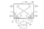
図8は、本発明の第7実施形態による交換流量を自動制御する固定式熱交換装置において、温度測定装置及び気相または液相流体成分測定装置を配置する構造を示す模式図である。
図8に示すように、本発明の第7実施形態の主なを構成は、熱交換装置1000の二流路流体の流体口a、流体口b、流体口c、流体口dの中の流体口b及び流体口dに、それぞれ負圧または正圧を形成する二方向流体ポンプ111、112を設置し、二流路流体ポンピング装置123を構成することにより、電源300の電気エネルギーに駆動される制御装置250により、二流路流体ポンピング装置123の中で負圧または正圧を形成する二方向流体ポンプ111、112を制御し、二つの流体をポンピングし、熱交換体100へ流れる流向が異なる。
(Seventh embodiment)
FIG. 8 is a schematic diagram showing a structure in which a temperature measurement device and a gas phase or liquid phase fluid component measurement device are arranged in a fixed heat exchange device that automatically controls the exchange flow rate according to the seventh embodiment of the present invention.
As shown in FIG. 8, the main configuration of the seventh embodiment of the present invention is the fluid port a, the fluid port b, the fluid port c, and the fluid port d in the fluid port d of the
熱交換装置1000と負圧または正圧を形成する二方向流体ポンプ111、112は、一体または分離設置により、二流路流体ポンピング装置123の機能を構成することができ、二つの負圧または正圧を形成する二方向流体ポンプ111、112をそれぞれ流体口b及び流体口dに設置することにより、流体を異なる流向へポンピングする。上述の負圧または正圧を形成する二方向流体ポンプ111、112は、個別に電力モータを設置して駆動し、または同一電力モータを共用して駆動してもよく、制御装置250の制御を通して、ニーズによって、以下の一種または一種以上の機能様式の作動を含む。(1)二つの二方向流体ポンプ111、112により負圧のポンピングを行い、熱交換体100を通過する二流路流体を異なる流向へ圧送する。(2)二つの二方向流体ポンプ111、112により正圧のポンピングを行い、熱交換体100を通過する二流路流体を異なる流向へ圧送する。
The two-way fluid pumps 111 and 112 that form a negative pressure or a positive pressure with the
直接または間接的に圧送する交換流体の温度変化を測定できる位置に、少なくとも一つの温度測定装置11を設置し、かつ圧送する気相または液相流体成分変化を測定できる位置に、少なくとも一つの気相または液相流体成分測定装置31の二者或いは少なくともその中の一種を設置することを含み、測定信号を、制御装置250により制御する二流路流体ポンピング装置123により圧送する交換流体流量の大小の制御時機の参考とする。
At least one
上述の温度測定装置11及び気相または液相流体成分測定装置31は、一体構造または分離して設置することができる。
二流路流体ポンピング装置123は、二流路流体の流体口a、流体口b、流体口c、流体口dの中の流体口b及び流体口dに、それぞれ負圧または正圧を形成する二方向流体ポンプ111、112を設置することにより構成される。制御装置250を通して、電源300により駆動する二流路流体ポンピング装置123により圧送する熱交換流体流量の大小を制御する。
The
The two-channel
電源300は、第7実施形態の交換流量を自動制御する固定式熱交換装置の作動電源を提供し、交流または直流の市内電源システムまたは独立型電気エネルギー供給装置を含む。
制御装置250は、メカトロニックスコンポーネント、固相電子回路コンポーネント、またはマイクロプロセッサ及び関連ソフトウェア及び制御インターフェースにより構成することにより、二流路流体ポンピング装置123の二方向流体ポンプ111、112に対して、(1)開閉機能を作動するか、または(2)熱交換流体のポンピング流量を制御するか、または(3)流体と熱交換装置1000の中の熱交換体100の温度分布状態を制御するか、または(4)熱交換装置1000の両側の間を通して、熱交換の気相または液相流体成分の交流状態を制御するか、または(5)前述の(1)(2)(3)(4)項目の中で少なくとも二項目を統合して制御する。
The
The
熱交換体100は、内部に二つの流体通路を有し、また吸熱または放熱機能の熱交換体を有し、二つの流体通路は個別に二つの流体口を有することにより、それぞれ流体を圧送し、また二つの流体間で熱交換できる良く使われる熱交換構造である。
熱交換流体流量の大小を制御する時機は、(1)流体流量及び変換時間の開ループ制御をプリセットするか、または(2)人為的に制御することにより任意制御するか、または(3)直接または間接的に圧送する気相または液相流体の温度変化を測定できる位置に、少なくとも一つの温度測定装置11を設置し、または少なくとも一つの気相または液相流体成分測定装置31の二者或いは少なくともその中の一種を設置することを含み、測定信号を、圧送する交換流体流量の大小の制御時機の参考とする。
この他に、上述の図8の第7実施形態はまた二方向流体ポンプ111及び二方向流体ポンプ112を流体口a、dに設置し、或いは流体口b、cに設置してもよく、かつその中の一つの二方向流体ポンプにより正圧でポンピングする。別の二方向流体ポンプは負圧のポンピングにより、熱交換体100を通過する二流路流体を異なる流向へ圧送する。
The
The timing for controlling the magnitude of the heat exchange fluid flow is either (1) preset open-loop control of fluid flow and conversion time, or (2) arbitrarily control by artificial control, or (3) directly Alternatively, at least one
In addition, the seventh embodiment of FIG. 8 described above may also install the two-
(第8実施形態)
図9は、本発明の第8実施形態による交換流量を自動制御する固定式熱交換装置において、温度測定装置及び気相または液相流体成分測定装置を配置する構造を示す模式図である。
図9に示すように、本発明の第8実施形態の主な構成は、熱交換装置1000の二流路流体の二流路通路を通過する流体口a、流体口b、流体口c、流体口dに、それぞれ一流向へポンピングする一方向流体ポンプ120a、120b、120c、120dを設置することにより、二流路流体ポンピング装置123を構成する。電源300の電気エネルギーを通して、制御装置250により二流路流体ポンピング装置123により圧送する二流路流体へ流れる熱交換体100の流向は異なるものを制御する。
(Eighth embodiment)
FIG. 9 is a schematic diagram showing a structure in which a temperature measurement device and a gas phase or liquid phase fluid component measurement device are arranged in a fixed heat exchange device that automatically controls the exchange flow rate according to the eighth embodiment of the present invention.
As shown in FIG. 9, the main configuration of the eighth embodiment of the present invention is that a fluid port a, a fluid port b, a fluid port c, and a fluid port d that pass through the two channel passages of the two channel fluid of the
熱交換装置1000と一方向流体ポンプ120a、120b、120c、120dは、一体または分離設置により、二流路流体ポンピング装置123の機能を構成することができ、四つの一方向流体ポンプ120a、120b、120c、120dをそれぞれ流体口a、流体口b、流体口c、流体口dに設置することにより、流体をポンピングする。その中の流体口a及び流体口cに設置する一方向流体ポンプ120a、120cは1セットであり、個別に電力モータにより駆動され、または同一電力モータを共用して駆動してもよく、流体口b及び流体口dに設置する一方向流体ポンプ120b、120dは別セットであり、個別に設置する電力モータにより駆動され、または同一電力モータを共用して駆動してもよく、制御装置250を通して制御し、以下の一種または一種以上の機能様式の構造形態及び作動方式を有する。(1)一方向流体ポンプが流体に対して、負圧のポンピング構造を設置することにより、二流路流体を異なる流向にする。または(2)一方向流体ポンプが流体に対して、正圧のポンピング構造を設置することにより、二流路流体を異なる流向にする。または(3)その中の一部または全部の一方向流体ポンプ120a、120b、120c、120dが同じ流路に異なる流体ポンプにより、正圧のポンピング及び負圧のポンピングにより、補助ポンピングを形成し、また二流路流体を異なる流向へ圧送する。前述の項目(1)、(2)、(3)の機能様式が作動するとき、熱交換装置1000内部の熱交換体100の両側を通過する二流路流体の流向は、全て逆に維持する。
The
直接または間接的に圧送する交換流体の温度変化を測定できる位置に、少なくとも一つの温度測定装置11を設置し、かつ圧送する気相または液相流体成分変化を測定できる位置に、少なくとも一つの気相または液相流体成分測定装置31を設置し、二者或いは少なくともその中の一種を設置することを含み、測定信号を、制御装置250により制御する二流路流体ポンピング装置123により圧送する交換流体流量の大小の制御時機の参考とする。
At least one
上述の温度測定装置11及び気相または液相流体成分測定装置31は、一体構造または分離して設置することができる。
二流路流体ポンピング装置123は、二流路流体の流体口a、流体口b、流体口c、流体口dに、それぞれ一方向へポンピングする一方向流体ポンプ120a、120b、120c、120dを設置することにより構成される。制御装置250を通して、電源300により駆動する二流路流体ポンピング装置123により圧送する熱交換流体流量の大小を制御する。
The
The two-channel
電源300は、第8実施形態の交換流量を自動制御する固定式熱交換装置の作動電源を提供し、交流または直流の市内電源システムまたは独立型電気エネルギー供給装置を含む。
制御装置250は、メカトロニックスコンポーネント、固相電子回路コンポーネント、またはマイクロプロセッサ及び関連ソフトウェア及び制御インターフェースにより構成することにより、二流路流体ポンピング装置123の各一方向流体ポンプ120a、120b、120c、120dに対して、(1)開閉機能を作動するか、または(2)熱交換流体のポンピング流量を制御するか、または(3)流体と熱交換装置1000の中の熱交換体100の温度分布状態を制御するか、または(4)熱交換装置1000の両側の間を通して、熱交換の気相または液相流体成分の交流状態を制御するか、または(5)前述の(1)(2)(3)(4)項目の中で少なくとも二項目を統合して制御する。
The
The
熱交換体100は、内部に二つの流体通路を有し、また吸熱または放熱機能の熱交換体を有し、二つの流体通路は個別に二つの流体口を有することにより、それぞれ流体を圧送し、また二つの流体間で熱交換できる良く使われる熱交換構造である。
熱交換流体流量の大小を制御する時機は、(1)流体流量及び変換時間の開ループ制御をプリセットするか、または(2)人為的に制御することにより任意制御するか、または(3)直接または間接的に圧送する気相または液相流体の温度変化を測定できる位置に、少なくとも一つの温度測定装置11を設置し、または少なくとも一つの気相または液相流体成分測定装置31を設置し、二者或いは少なくともその中の一種を設置することを含み、測定信号を、圧送する交換流体流量の大小の制御時機の参考とする。
The
The timing for controlling the magnitude of the heat exchange fluid flow is either (1) preset open-loop control of fluid flow and conversion time, or (2) arbitrarily control by artificial control, or (3) directly Alternatively, at least one
(第9実施形態)
図10は、本発明の第9実施形態による交換流量を自動制御する固定式熱交換装置において、温度測定装置及び湿度測定装置及び気相または液相流体成分測定装置を配置する構造を示す模式図である。
図10に示すように、本発明の第9実施形態の主な構成は、熱交換装置1000の二流路流体の流体口a、流体口b、流体口c、流体口dの中の流体口b及び流体口dに、それぞれ負圧または正圧を形成する二方向流体ポンプ111、112を設置し、二流路流体ポンピング装置123を構成することにより、制御装置250を通して、電源300により駆動する二流路流体ポンピング装置123の中で負圧または正圧を形成する二方向流体ポンプ111、112を制御し、二流路流体を異なる流向へポンピングする。
(Ninth embodiment)
FIG. 10 is a schematic diagram showing a structure in which a temperature measurement device, a humidity measurement device, and a gas phase or liquid phase fluid component measurement device are arranged in a fixed heat exchange device that automatically controls the exchange flow rate according to the ninth embodiment of the present invention. It is.
As shown in FIG. 10, the main configuration of the ninth embodiment of the present invention is that the fluid port a, the fluid port b, the fluid port c, and the fluid port b in the fluid port d of the two-channel fluid of the
熱交換装置1000と負圧または正圧を形成する二方向流体ポンプ111、112は、一体または分離設置により、二流路流体ポンピング装置123の機能を構成することができ、二つの負圧または正圧を形成する二方向流体ポンプ111、112をそれぞれ流体口b及び流体口dに設置することにより、流体を異なる流向へポンピングする。上述の負圧または正圧を形成する二方向流体ポンプ111、112は、個別に電力モータを設置して駆動し、または同一電力モータを共用して駆動してもよく、制御装置250の制御を通して、ニーズによって、以下の一種または一種以上の機能様式の作動を含む。(1)その中の二つの二方向流体ポンプ111、112により負圧のポンピングを行い、全熱交換体200を通過する二流路流体を異なる流向へ圧送する。(2)その中の二つの二方向流体ポンプ111、112により正圧のポンピングを行い、全熱交換体200を通過する二流路流体を異なる流向へ圧送する。前述(1)、(2)種類の機能様式が作動するとき、熱交換装置1000内部の全熱交換体200の両側を通過する二流路流体の流向は、全て逆に維持する。
The two-way fluid pumps 111 and 112 that form a negative pressure or a positive pressure with the
直接または間接的に圧送する交換流体の温度変化、湿度変化、または気相また液相流体の成分変化を測定できる位置に、少なくとも一つの温度測定装置11、または湿度測定装置21、または少なくとも一つの気相または液相流体成分測定装置31、の三者或いは少なくともその中の一種を設置することを含み、測定信号を、制御装置250により制御する二流路流体ポンピング装置123により圧送する交換流体流量の大小の制御時機の参考とする。
At least one
上述の温度測定装置11と湿度測定装置21と気相また液相流体成分測定装置31は、一体構造または分離して設置することができる。
二流路流体ポンピング装置123は、二流路流体の流体口b、流体口dに、それぞれ負圧または正圧を形成する二方向流体ポンプ111、112を設置することにより構成され、制御装置250を通して、電源300により駆動する二流路流体ポンピング装置123により圧送する熱交換流体流量の大小を制御する。
The
The two-channel
電源300は、第9実施形態の交換流量を自動制御する固定式熱交換装置の作動電源を提供し、交流または直流の市内電源システムまたは独立型電気エネルギー供給装置を含む。
制御装置250は、メカトロニックスコンポーネント、固相電子回路コンポーネント、またはマイクロプロセッサ及び関連ソフトウェア及び制御インターフェースにより構成することにより、二流路流体ポンピング装置123の二方向流体ポンプ111、112に対して、(1)開閉機能を作動するか、または(2)熱交換流体のポンピング流量を制御するか、または(3)流体と熱交換装置1000の中の全熱交換体200の温度分布状態を制御するか、または(4)全熱交換体200の中の湿度の分≡状態を制御するか、または(5)熱交換装置1000の両側の間を通して、熱交換の気相または液相流体成分の交流状態を制御するか、または(6)前述の項目(1)、(2)、(3)、(4)、(5)の中で少なくとも二項目を統合して制御する。
The
The
全熱交換体200は、内部に二つの流体通路を有し、吸熱または放熱及び湿度を吸収または放出機能を持つ全熱交換体を有し、二つの流体通路は個別の流体口を有し、それぞれ流体を圧送し、また二つの流体間で熱交換及び除湿機能を働かせることができ、よく使われる全熱交換構造である。
熱交換流体流量の大小を制御する時機は、(1)流体流量及び変換時間の開ループ制御をプリセットするか、または(2)人為的に制御することにより任意制御するか、または(3)直接または間接に圧送する交換流体の温度、湿度変化、或いは気相または液相流体の成分変化を測定できる位置に、少なくとも一つの温度測定装置11、または少なくとも一つの湿度測定装置21、または少なくとも一つの気相または液相流体成分測定装置31の三者或いは少なくともその中の一種の測定装置を設置することを含み、測定信号を、圧送する交換流体流量の大小の制御時機の参考とする。
The
The timing for controlling the magnitude of the heat exchange fluid flow is either (1) preset open-loop control of fluid flow and conversion time, or (2) arbitrarily control by artificial control, or (3) directly Alternatively, at least one
熱交換流体流量の大小を制御する時機は、(1)流体流量及び変換時間の開ループ制御をプリセットするか、または(2)人為的に制御することにより任意制御するか、または(3)直接または間接に圧送する気相または液相流体の温度変化を測定できる位置に、少なくとも一つの温度測定装置11、または少なくとも一つの気相または液相流体成分測定装置31の二者或いは少なくともその中の一種を設置することを含み、測定信号を、圧送する交換流体流量の大小の制御時機の参考とする。
この他に、上述の図10の第9実施形態は、また二方向流体ポンプ111及び二方向流体ポンプ112を流体口a、dに設置し、或いは流体口b、cに設置することができ、かつその中の一つの二方向流体ポンプにより正圧でポンピングする。別の二方向流体ポンプは負圧のポンピングにより、全熱交換体200を通過する二流路流体を異なる流向へ圧送する。
The timing for controlling the magnitude of the heat exchange fluid flow is either (1) preset open-loop control of fluid flow and conversion time, or (2) arbitrarily control by artificial control, or (3) directly Alternatively, at least one
In addition, the ninth embodiment of FIG. 10 described above can also install the two-
(第10実施形態)
図11は、本発明の第10実施形態による交換流量を自動制御する固定式熱交換装置において、温度測定装置及び湿度測定装置及び気相または液相流体成分測定装置を配置する構造を示す模式図である。
図11に示すように、本発明の第10実施形態の主な構成は熱交換装置1000の二流路流体の二流路通路を通過する流体口a、流体口b、流体口c、流体口dに、それぞれ一流向へポンピングする一方向流体ポンプ120a、120b、120c、120dを設置することにより、二流路流体ポンピング装置123を構成し、電源300の電気エネルギーを通して、二流路流体ポンピング装置123を制御し、かつ二流路流体ポンピング装置123にポンピングされる二流路流体の流向は異なる。
(10th Embodiment)
FIG. 11 is a schematic diagram showing a structure in which a temperature measurement device, a humidity measurement device, and a gas phase or liquid phase fluid component measurement device are arranged in a fixed heat exchange device that automatically controls the exchange flow rate according to the tenth embodiment of the present invention. It is.
As shown in FIG. 11, the main configuration of the tenth embodiment of the present invention is a fluid port a, a fluid port b, a fluid port c, and a fluid port d that pass through the two channel passages of the two channel fluid of the
熱交換装置1000と一方向流体ポンプ120a、120b、120c、120dは、一体または分離設置により、二流路流体ポンピング装置123の機能を構成することができ、四つの一方向流体ポンプ120a、120b、120c、120dをそれぞれ流体口a、流体口b、流体口c、流体口dに設置することにより、流体をポンピングする。その中の流体口a及び流体口cに設置する一方向流体ポンプ120a、120cは1セットであり、個別に電力モータにより駆動され、または同一電力モータを共用して駆動してもよく、流体口b及び流体口dに設置する一方向流体ポンプ120b、120dは別セットであり、個別に設置する電力モータにより駆動され、または同一電力モータを共用して駆動してもよく、制御装置250を通して制御し、以下の一種または一種以上の機能様式の構造形態及び作動方式を有する。(1)一方向流体ポンプが流体に対して、負圧のポンピング構造を設置することにより、二流路流体を異なる流向にする。または(2)一方向流体ポンプが流体に対して、正圧のポンピング構造を設置することにより、二流路流体を異なる流向にする。または(3)上述の一部または全部の一方向流体ポンプ120a、120b、120c、120dの同じ流路の異なる流体ポンプが、正圧のポンピング及び負圧のポンピングにより、補助ポンピングを形成し、また二流路流体を異なる流向へ圧送する。
The
直接または間接的に圧送する交換流体の温度変化、湿度変化、または気相また液相流体の成分変化を測定できる位置に、少なくとも一つの温度測定装置11、または湿度測定装置21、または少なくとも一つの気相または液相流体成分測定装置31の三者或いは少なくともその中の一種を設置することを含み、測定信号を、制御装置250により制御する二流路流体ポンピング装置123により圧送する交換流体流量の大小の制御時機の参考とする。
At least one
上述の温度測定装置11と湿度測定装置21と気相また液相流体成分測定装置31は、一体構造または分離して設置することができる。
二流路流体ポンピング装置123は、二流路流体の流体口a、流体口b、流体口c、流体口dに、それぞれ一方向へポンピングする一方向流体ポンプ120a、120b、120c、120dを設置することにより構成され、制御装置250を通して、電源300により駆動する二流路流体ポンピング装置123により圧送する熱交換流体流量の大小を制御する。
電源300は、第10実施形態の交換流量を自動制御する固定式熱交換装置の作動電源を提供し、交流または直流の市内電源システムまたは独立型電気エネルギー供給装置を含む。
The
The two-channel
The
制御装置250は、メカトロニックスコンポーネント、固相電子回路コンポーネント、またはマイクロプロセッサ及び関連ソフトウェア及び制御インターフェースにより構成することにより、二流路流体ポンピング装置123の一方向流体ポンプ120a、120b、120c、120dに対して、(1)開閉機能を作動するか、または(2)熱交換流体のポンピング流量を制御するか、または(3)流体と熱交換装置1000の中の全熱交換体200の温度分布状態を制御するか、または(4)全熱交換体200の中の湿度の分≡状態を制御するか、または(5)熱交換装置1000の両側の間を通して、熱交換の気相または液相流体成分の交流状態を制御するか、または(6)前述の項目(1)、(2)、(3)、(4)、(5)の中で少なくとも二項目を統合して制御する。
The
制御装置250は、メカトロニックスコンポーネント、固相電子回路コンポーネント、またはマイクロプロセッサ及び関連ソフトウェア及び制御インターフェースにより構成することにより、二流路流体ポンピング装置123の各一方向流体ポンプ120a、120b、120c、120dに対して、(1)開閉機能を作動するか、または(2)熱交換流体のポンピング流量を制御するか、または(3)流体と熱交換装置1000の中の全熱交換体200の温度分布状態を制御するか、または(4)全熱交換体200の湿度分布状態を制御するか、または(5)熱交換装置1000の両側の間を通して、熱交換の気相または液相流体成分の交流状態を制御するか、または(6)前述の項目(1)、(2)、(3)、(4)、(5)の中で少なくとも二項目を統合して制御する。
The
全熱交換体200は、内部に二つの流体通路を有し、吸熱または放熱及び湿度を吸收または放出機能を持つ全熱交換体を有し、二つの流体通路は個別の流体口を有し、それぞれ流体を圧送し、また二つの流体間で熱交換及び除湿機能を働かせることができ、よく使われる全熱交換構造である。
熱交換流体流量の大小を制御する時機は、(1)流体流量及び変換時間の開ループ制御をプリセットするか、または(2)人為的に制御することにより任意制御するか、または(3)直接または間接に圧送する交換流体の温度、湿度変化、或いは気相または液相流体の成分変化を測定できる位置に、少なくとも一つの温度測定装置11、または少なくとも一つの湿度測定装置21、または少なくとも一つの気相または液相流体成分測定装置31の三者或いは少なくともその中の一種の測定装置を設置することを含み、測定信号を通して、圧送する交換流体流量の大小の制御時機の参考とする。
The
The timing for controlling the magnitude of the heat exchange fluid flow is either (1) preset open-loop control of fluid flow and conversion time, or (2) arbitrarily control by artificial control, or (3) directly Alternatively, at least one
本発明の実施形態による交換流量を自動制御する固定式熱交換装置において、熱交換体または全熱交換体の構造形態に関し、以下の一種または一種以上の特徴を有する。(1)線形またはその他幾何形状の管状構造を呈すことができる。または(2)気相または液相の流体通路が通過する多層構造体により構成することができる。または(3)ワンウェイまたはワンウェイ以上の流体通路を直列接続、または並列接続、または直並列接続により構成することができる。 The fixed heat exchange apparatus that automatically controls the exchange flow rate according to the embodiment of the present invention has the following one type or one or more features regarding the structural form of the heat exchanger or the total heat exchanger. (1) It can exhibit a linear or other geometric tubular structure. Or (2) It can be constituted by a multilayer structure through which a gas phase or liquid phase fluid passage passes. Or (3) One-way or one-way or more fluid passages can be configured by series connection, parallel connection, or series-parallel connection.
本発明の実施形態による交換流量を自動制御する固定式熱交換装置は、更に、温度測定装置11、湿度測定装置21、気相または液相流体成分測定装置31の三者を全部設置し、または少なくともその中の一種または一種以上の測定装置を設置することができ、設置位置は、熱交換装置1000、熱交換体100、または全熱交換体200の流体口a及び流体口bの二つの位置またはその中の一つの近くに設置し、または流体口c及び流体口dの二つの位置またはその中の一つに、またはその他熱交換が作動するときに、交換流体の温度または湿度または流体の成分を測定できる位置に設置することを含む。その数量は一つまたは一つ以上であることができ、測定信号を参考して、以下の一種または一種以上の機能を操作することを含む。(1)二流路流体ポンピング装置123を制御することにより、ポンピングする流体流速の速さまたは流量の大小の制御時機の參考とする。または(2)流体バルブのオープン量を制御することにより、ポンピングする流体流速の速さまたは流量の大小の制御時機の参考とする。
The fixed heat exchange device for automatically controlling the exchange flow rate according to the embodiment of the present invention further includes all three members of the
上述の温度測定装置11、湿度測定装置21、気相または液相流体の成分測定装置31は、全部の測定装置を同一構造であり、または一部の測定装置が同一構造であり、または分離設置することができる。
前述の本発明の実施形態による二流路流体ポンピング装置123は、気相または液相の流体をポンピングし、二流路流体ポンプ123は、個別に設置する電力モータにより駆動する以外に、または少なくとも二つの流体ポンプにより同一の電気駆動モータを共用し、またはエンジン動力を通して、またはその他風エネルギー、熱エネルギー、温度差エネルギー、または太陽エネルギーにより生じ、転換される機械エネルギーまたは電気エネルギーにより駆動することができる。
The above-described
The above-described two-channel
前述の本発明の実施形態の制御装置250は、各種の流体ポンプを駆動する電力モータを制御し、またはエンジン動力を制御し、またはその他風エネルギー、熱エネルギー、温度差エネルギー、太陽エネルギーにより生じ、転換される機械エネルギー或いは電気エネルギーを制御し、または流体ポンプまたは流体バルブの作動時機を制御することにより、熱交換体100を通過する二流路の中の流体流向を変更させ、更に各流体ポンプの回転速度、流量、流体圧力等の一部機能或いは全部機能を制御することができる。
The
前述の本発明の実施形態の交換流量を自動制御する固定式熱交換装置は、更に制御装置250を通して、二流路流体ポンピング装置123により圧送する流体の流量の大小を制御し、その制御様式は以下の一種または一種以上を含む。
(1)人力で調整または設定することにより制御する。
(2)少なくとも一つの温度測定装置を設置し、その測定信号を参考して制御する。
(3)少なくとも一つの湿度測定装置を設置し、その測定信号を参考して制御する。
(4)少なくとも一つの気相または液相流体の成分測定装置を設置し、その測定信号を参考して制御する。
(5)上記(1)〜(4)の中の2種類のまたは2種類の以上の方式を統合して制御する。
The fixed heat exchange device that automatically controls the exchange flow rate according to the above-described embodiment of the present invention further controls the flow rate of the fluid pumped by the two-channel
(1) Control by adjusting or setting manually.
(2) At least one temperature measuring device is installed and controlled with reference to the measurement signal.
(3) At least one humidity measuring device is installed and controlled with reference to the measurement signal.
(4) At least one component measurement device for gas phase or liquid phase fluid is installed and controlled with reference to the measurement signal.
(5) The two types of the above (1) to (4) or two or more types are integrated and controlled.
本発明の実施形態の交換流量を自動制御する固定式熱交換装置に流量制御機能を設置するときに、その流体流量制御範囲は、輸送停止から最大輸送量までの間に、作動のニーズによって流体流量を有段または無段に制御することができ、また以下の一種或いは一種以上の装置を通して、その流体流量を変更させることを含む。
(1)二流路流体ポンピング装置123のポンピング作動時の回転速度を制御し、作動停止から最高速度の範囲内の速度を控制してから、更にその流体の流量を制御する。
When the flow rate control function is installed in the fixed heat exchange device that automatically controls the exchange flow rate according to the embodiment of the present invention, the fluid flow rate control range depends on the operation needs between the transportation stoppage and the maximum transportation amount. The flow rate can be controlled stepwise or continuously, and includes changing the fluid flow rate through one or more of the following devices.
(1) The rotational speed at the time of pumping operation of the two-channel
(2)流体の出入りを制御できるバルブ口を持つ二流路流体ポンピング装置123を採用することにより、二流路流体ポンピング装置123の流体が出入りするバルブ口のオープン量を制御し、更にその流体流量を制御する。
(3)(1)〜(2)の制御項目の中のいかなる装置で、流体を間欠圧送し、かつ圧送または圧送停止の二者の時間比により、その平均流量を制御する。
(2) By adopting the two-channel
(3) With any device in the control items of (1) to (2), the fluid is intermittently pumped, and the average flow rate is controlled by the time ratio between the pumping and the pumping stop.
本発明の実施形態の交換流量を自動制御する固定式熱交換装置が作動するとき、その熱交換装置1000を通過する二流路流体の流量比は、以下の一種または一種以上の割合様式を含む。
(1)その中の一流路の流体流量が別の流路より大きい。
(2)その二流路流体の流量が同じである。
(3)二つの流体を異なる流向へポンピングする液体ポンプが交替して作動することにより、交替して逆流向を示す二流路流体をポンピングする。
When the fixed heat exchange device that automatically controls the exchange flow rate according to the embodiment of the present invention operates, the flow rate ratio of the two-channel fluid passing through the
(1) The fluid flow rate in one flow path is larger than that in another flow path.
(2) The flow rate of the two-channel fluid is the same.
(3) A liquid pump that pumps two fluids in different flow directions operates alternately to pump a two-channel fluid that alternates and shows a reverse flow direction.
本発明の実施形態の交換流量を自動制御する固定式熱交換装置は、二流路の異なる流向の流体を圧送する以外に、二流路流体ポンピング装置123を二方向へポンピングする二つの流体ポンプにより構成するときに、二流路流体のポンピング流向の制御を通して、更に一歩進んで、同時に以下の一種または一種以上の特別な作動様式を含む。
(1)二流路の流体を制御し、同じ流向の流体をポンプインする。
(2)二流路の流体を制御し、同じ流向の流体を逆方向へポンプアウトする。
(3)二流路の流体を制御し、同じ流向の流体をポンプインし、かつ逆方向へ流体を周期的に正逆ポンプでポンプアウトする。
上述の二流路流体の同じ流向への圧送機能は、緊急時の流体流量をポンプインまたはポンプアウトのニーズへの応用が可能である。
The fixed heat exchange device that automatically controls the exchange flow rate according to the embodiment of the present invention is configured by two fluid pumps that pump the two-channel
(1) The fluid in the two flow paths is controlled, and the fluid in the same flow direction is pumped in.
(2) Control the fluid in the two flow paths and pump out the fluid in the same flow direction in the opposite direction.
(3) The fluid in the two flow paths is controlled, the fluid in the same flow direction is pumped in, and the fluid is periodically pumped out by the forward / reverse pump in the reverse direction.
The above-described function of pumping the two-channel fluid in the same flow direction can be applied to the need for pumping in or pumping out the fluid flow rate in an emergency.
11:温度測定装置、21:湿度測定装置、31:気相または液相流体成分測定装置、100:熱交換体、111、112:負圧または正圧を形成する二方向流体ポンプ、120a、120b、120c、120d:一方向流体ポンプ、123:二流路流体ポンピング装置、200:全熱交換体、300:電源、250:制御装置、1000:熱交換装置、a、b、c、d:流体口 11: Temperature measuring device, 21: Humidity measuring device, 31: Gas phase or liquid phase fluid component measuring device, 100: Heat exchanger, 111, 112: Two-way fluid pump for forming negative pressure or positive pressure, 120a, 120b , 120c, 120d: one-way fluid pump, 123: two-channel fluid pumping device, 200: total heat exchanger, 300: power supply, 250: control device, 1000: heat exchanger, a, b, c, d: fluid port
Claims (23)
構成としては、熱交換装置(1000)の二流路流体の第一流体口(a)、第二流体口(b)、第三流体口(c)、第四流体口(d)の中の前記第二流体口(b)及び前記第四流体口(d)に、それぞれ負圧または正圧を形成する二方向流体ポンプ(111、112)を設置して、二流路流体ポンピング装置(123)を構成し、制御装置(250)により、電源(300)の電気エネルギーに駆動される前記二流路流体ポンピング装置(123)の中で負圧または正圧を形成する前記二方向流体ポンプ(111、112)を制御することにより、二つの流体をポンピングし、熱交換体(100)へ流れる流向が異なるように制御し、
前記熱交換装置(1000)と負圧または正圧を形成する前記二方向流体ポンプ(111、112)とは、一体または分離設置により、前記二流路流体ポンピング装置(123)の機能を構成し、二つの負圧または正圧を形成する前記二方向流体ポンプ(111、112)をそれぞれ前記第二流体口(b)及び前記第四流体口(d)に設置することにより、流体を異なる流向へポンピングし、負圧または正圧を形成する前記二方向流体ポンプ(111、112)は、個別に電力モータを設置して駆動し、または同一電力モータを共用して駆動してもよく、前記制御装置(250)の制御を通して、機能様式として、二つの前記二方向流体ポンプ(111、112)により負圧のポンピングを行い、前記熱交換体(100)を通過する二流路流体を異なる流向へ圧送する機能様式、または、二つの前記二方向流体ポンプ(111、112)により正圧のポンピングを行い、前記熱交換体(100)を通過する二流路流体を異なる流向へ圧送する機能様式の一種または一種以上の作動を含み、
前記二流路流体ポンピング装置(123)は、二流路流体の前記第一流体口(a)、前記第二流体口(b)、前記第三流体口(c)、前記第四流体口(d)の中の前記第二流体口(b)及び前記第四流体口(d)に、それぞれ負圧または正圧を形成する前記二方向流体ポンプ(111、112)を設置することにより構成され、前記制御装置(250)を通して、前記電源(300)により駆動され、圧送する熱交換流体流量の大小を制御し、
前記電源(300)は、作動電源を提供し、交流または直流の市内電源システムまたは独立型電気エネルギー供給装置であってもよく、
前記制御装置(250)は、メカトロニックスコンポーネント、固相電子回路コンポーネント、またはマイクロプロセッサ及び関連ソフトウェア及び制御インターフェースにより構成され、前記二流路流体ポンピング装置(123)の前記二方向流体ポンプ(111、112)の制御は、開閉機能を作動するか、または、熱交換流体のポンピング流量を制御するか、または、流体と前記熱交換装置(1000)の中の前記熱交換体(100)の温度分布状態を制御するか、または、これらの二項目を統合して制御し、
前記熱交換体(100)は、内部に二つの流体通路を有し、また吸熱または放熱機能の熱交換体を有し、二つの前記流体通路は個別に二つの前記第一流体口(a)及び前記第二流体口(b)、または前記第三流体口(c)及び前記第四流体口(d)を有することにより、それぞれ流体を圧送し、また二つの流体間で熱交換可能な良く使われる熱交換構造であり、
熱交換流体流量の大小を制御する時機は、流体流量及び変換時間の開ループ制御をプリセットするか、または、人為的に制御することにより任意制御することを特徴とする交換流量を自動制御する固定式熱交換装置。 It has an operation function that automatically controls the fluid exchange flow rate, changes the temperature distribution state between the fluid and the heat exchange turntable at the appropriate time, or controls the ratio of the gas phase or liquid phase fluid component to be pumped, In addition, when a penetration type or adsorption type hygroscopic material is sandwiched or applied to the internal heat exchange turntable, or when the main body is a heat exchange turntable having a hygroscopic function, the dehumidifying effect of the total heat exchange function Configure
As a configuration, the first fluid port (a), the second fluid port (b), the third fluid port (c), and the fourth fluid port (d) of the two-channel fluid of the heat exchange device (1000) Two-way fluid pumps (111, 112) for forming a negative pressure or a positive pressure are installed in the second fluid port (b) and the fourth fluid port (d), respectively, and the two-channel fluid pumping device (123) is installed. The two-way fluid pump (111, 112) configured and configured to create a negative or positive pressure in the two-channel fluid pumping device (123) driven by the electrical energy of the power source (300) by the controller (250) ) To control the flow of the two fluids to the heat exchanger (100) to be different,
The heat exchange device (1000) and the two-way fluid pump (111, 112) that forms a negative pressure or a positive pressure constitute a function of the two-channel fluid pumping device (123) by integral or separate installation, By installing the two-way fluid pumps (111, 112) forming two negative pressures or positive pressures in the second fluid port (b) and the fourth fluid port (d), respectively, the fluids are moved in different flow directions. The two-way fluid pump (111, 112) that pumps and generates negative pressure or positive pressure may be driven by separately installing a power motor, or may be driven by sharing the same power motor. Through the control of the device (250), as a function mode, the two-way fluid pumps (111, 112) perform negative pressure pumping and the two-channel flow passing through the heat exchanger (100). Mode of pumping the fluid in different flow directions, or performing positive pressure pumping by the two bidirectional fluid pumps (111, 112) and pumping the two-channel fluid passing through the heat exchanger (100) in different flow directions Including one or more functions of function style,
The two-channel fluid pumping device (123) includes the first fluid port (a), the second fluid port (b), the third fluid port (c), and the fourth fluid port (d) for a two-channel fluid. The two-way fluid pumps (111, 112) that form a negative pressure or a positive pressure are installed in the second fluid port (b) and the fourth fluid port (d), respectively, Controlling the magnitude of the flow rate of heat exchange fluid to be pumped and driven by the power source (300) through the control device (250),
The power source (300) provides an operating power source and may be an AC or DC city power system or a stand-alone electrical energy supply device,
The control device (250) is constituted by a mechatronic component, a solid phase electronic circuit component, or a microprocessor and related software and a control interface, and the two-way fluid pump (111, 112) of the two-channel fluid pumping device (123). ) Controls the opening / closing function, controls the pumping flow rate of the heat exchange fluid, or the temperature distribution state of the fluid and the heat exchanger (100) in the heat exchange device (1000) Or control these two items together,
The heat exchanging body (100) has two fluid passages therein, and also has a heat exchanging or heat dissipating function, and the two fluid passages are individually provided with the two first fluid ports (a). And the second fluid port (b) or the third fluid port (c) and the fourth fluid port (d), so that the fluid can be pumped and heat can be exchanged between the two fluids. The heat exchange structure used,
The time to control the flow rate of heat exchange fluid is fixed to automatically control the exchange flow rate, which is preset by open loop control of fluid flow rate and conversion time, or arbitrarily controlled by artificial control Type heat exchanger.
前記熱交換装置(1000)、前記第一一方向流体ポンプ(120a)、前記第二一方向流体ポンプ(120b)、前記第三一方向流体ポンプ(120c)及び前記第四一方向流体ポンプ(120d)は、一体または分離設置により、前記二流路流体ポンピング装置(123)の機能を構成し、四つの前記第一一方向流体ポンプ(120a)、前記第二一方向流体ポンプ(120b)、前記第三一方向流体ポンプ(120c)及び前記第四一方向流体ポンプ(120d)をそれぞれ前記第一流体口(a)、前記第二流体口(b)、前記第三流体口(c)及び前記第四流体口(d)に設置することにより、流体をポンピングし、前記第一流体口(a)及び前記第三流体口(c)に設置する前記第一一方向流体ポンプ(120a)及び前記第三一方向流体ポンプ(120c)は1セットであり、個別に電力モータにより駆動され、または同一電力モータを共用して駆動されてもよく、前記第二流体口(b)及び前記第四流体口(d)に設置する前記第二一方向流体ポンプ(120b)及び前記第四一方向流体ポンプ(120d)は別セットであり、個別に設置する電力モータにより駆動され、または同一電力モータを共用して駆動されてもよく、前記制御装置(250)を通して制御し、機能様式として、前記一方向流体ポンプが流体に対して、負圧のポンピング構造を設置することにより、二流路流体を異なる流向にする機能様式、または、前記一方向流体ポンプが流体に対して、正圧のポンピング構造を設置することにより、二流路流体を異なる流向にする機能様式、または、一部または全部の前記第一一方向流体ポンプ(120a)、前記第二一方向流体ポンプ(120b)、前記第三一方向流体ポンプ(120c)及び前記第四一方向流体ポンプ(120d)の同じ流路の異なる流体ポンプが、正圧のポンピング及び負圧のポンピングにより、補助ポンピングを形成し、また二流路流体を異なる流向へ圧送する機能様式のうち一種または一種以上の構造形態及び作動形式を有し、前記三種類の機能様式が作動するとき、前記熱交換装置(1000)内部の前記熱交換体(100)の両側を通過する二流路流体の流向は、全て逆に維持され、
前記二流路流体ポンピング装置(123)は、二流路流体の前記第一流体口(a)、前記第二流体口(b)、前記第三流体口(c)及び前記第四流体口(d)に、それぞれ一方向へポンピングする前記第一一方向流体ポンプ(120a)、前記第二一方向流体ポンプ(120b)、前記第三一方向流体ポンプ(120c)及び前記第四一方向流体ポンプ(120d)を設置することにより構成され、前記制御装置(250)を通して、前記電源(300)により駆動され、圧送する熱交換流体流量の大小を制御し、
前記電源(300)は、作動電源を提供し、交流または直流の市内電源システムまたは独立型電気エネルギー供給装置であってもよく、
制御装置(250)は、メカトロニックスコンポーネント、固相電子回路コンポーネント、またはマイクロプロセッサ及び関連ソフトウェア及び制御インターフェースにより構成され、前記二流路流体ポンピング装置(123)の前記第一一方向流体ポンプ(120a)、前記第二一方向流体ポンプ(120b)、前記第三一方向流体ポンプ(120c)及び前記第四一方向流体ポンプ(120d)の制御は、開閉機能を作動するか、または、熱交換流体のポンピング流量を制御するか、または、流体と前記熱交換装置(1000)の中の前記熱交換体(100)の温度分布状態を制御するか、または、これらの三項目の中で少なくとも二項を統合して制御し、
前記熱交換体(100)は、内部に二つの前記流体通路を有し、また吸熱または放熱機能を有し、二つの前記流体通路は個別に二つの前記第一流体口(a)及び前記第二流体口(b)、または前記第三流体口(c)及び前記第四流体口(d)を有することにより、それぞれ流体を圧送し、また二つの流体間で熱交換可能な良く使われる熱交換構造であり、
熱交換流体流量の大小を制御する時機は、流体流量及び変換時間の開ループ制御をプリセットするか、または、人為的に制御することにより任意制御することを特徴とする請求項1に記載の交換流量を自動制御する固定式熱交換装置。 The structure of the function of automatically controlling the heat exchange flow rate of the fluid includes the first fluid port (a), the second fluid port (b), and the second fluid port (b) that pass through the two channel passages of the two channel fluid of the heat exchange device (1000). A first one-way fluid pump (120a), a second one-way fluid pump (120b), and a third one-way fluid that are pumped to the third fluid port (c) and the fourth fluid port (d), respectively. By installing the pump (120c) and the fourth one-way fluid pump (120d), the two-channel fluid pumping device (123) is configured, and the control device (250) is passed through the electric energy of the power source (300). The flow direction of the two-channel fluid flowing to the heat exchanger (100) pumped by the two-channel fluid pumping device (123) is controlled to be different,
The heat exchange device (1000), the first one-way fluid pump (120a), the second one-way fluid pump (120b), the third one-way fluid pump (120c), and the fourth one-way fluid pump (120d). ) Constitutes the function of the two-channel fluid pumping device (123) by integral or separate installation, and the four first one-way fluid pumps (120a), the second one-way fluid pump (120b), the first A three-way fluid pump (120c) and a fourth one-way fluid pump (120d) are connected to the first fluid port (a), the second fluid port (b), the third fluid port (c) and the first fluid port, respectively. The first one-way fluid pump (120a) and the first fluid pump (120a) installed in the first fluid port (a) and the third fluid port (c) by pumping fluid by being installed in the four fluid ports (d) Sanichi The directional fluid pump (120c) is a set and may be individually driven by a power motor or may be driven by sharing the same power motor, and the second fluid port (b) and the fourth fluid port (d). ) The second one-way fluid pump (120b) and the fourth one-way fluid pump (120d) installed in a separate set are driven by a power motor installed separately or driven by sharing the same power motor. Controlled through the control device (250), and as a function mode, the one-way fluid pump has a function of causing the two-channel fluid to flow differently by installing a negative pressure pumping structure with respect to the fluid. Mode, or a functional mode in which the one-way fluid pump makes the two-channel fluid flow in different directions by installing a positive pressure pumping structure with respect to the fluid, or a part thereof Or the same flow of all of the first one-way fluid pump (120a), the second one-way fluid pump (120b), the third one-way fluid pump (120c) and the fourth one-way fluid pump (120d). Fluid pumps with different paths form auxiliary pumping by positive pressure pumping and negative pressure pumping, and have one or more structural forms and operating forms among the functional forms that pump two-channel fluids in different flow directions. When the three types of functions are activated, the flow directions of the two-channel fluids passing through both sides of the heat exchanger (100) inside the heat exchanger (1000) are all maintained in reverse.
The two-channel fluid pumping device (123) includes the first fluid port (a), the second fluid port (b), the third fluid port (c), and the fourth fluid port (d) for a two-channel fluid. The first one-way fluid pump (120a), the second one-way fluid pump (120b), the third one-way fluid pump (120c), and the fourth one-way fluid pump (120d) that respectively pump in one direction. ), Is controlled by the power supply (300) through the control device (250), and controls the flow rate of the heat exchange fluid to be pumped.
The power source (300) provides an operating power source and may be an AC or DC city power system or a stand-alone electrical energy supply device,
The control device (250) is constituted by a mechatronic component, a solid phase electronic circuit component, or a microprocessor and related software and a control interface, and the first one-way fluid pump (120a) of the two-channel fluid pumping device (123). The control of the second one-way fluid pump (120b), the third one-way fluid pump (120c) and the fourth one-way fluid pump (120d) operates an open / close function or the heat exchange fluid. Control the pumping flow rate, or control the temperature distribution state of the fluid and the heat exchanger (100) in the heat exchanger (1000), or at least two of these three items Integrated and controlled,
The heat exchanger (100) includes two fluid passages therein and has a heat absorption or heat dissipation function, and the two fluid passages individually include the two first fluid ports (a) and the first fluid passages. By having two fluid ports (b) or the third fluid port (c) and the fourth fluid port (d), the heat used for pumping the fluid and exchanging heat between the two fluids can be used. An exchange structure,
2. The exchange according to claim 1, wherein the timing for controlling the magnitude of the heat exchange fluid flow rate is preset by open-loop control of fluid flow rate and conversion time, or is arbitrarily controlled by artificial control. A fixed heat exchanger that automatically controls the flow rate.
前記熱交換装置(1000)と負圧または正圧を形成する前記二方向流体ポンプ(111、112)とは、一体または分離設置により、前記二流路流体ポンピング装置(123)の機能を構成し、二つの負圧または正圧を形成する前記二方向流体ポンプ(111、112)をそれぞれ前記第二流体口(b)及び前記第四流体口(d)に設置することにより、流体を異なる流向へポンピングし、負圧または正圧を形成する前記二方向流体ポンプ(111、112)は、個別に電力モータを設置して駆動し、または同一電力モータを共用して駆動してもよく、前記制御装置(250)の制御を通して、機能様式として、二つの前記二方向流体ポンプ(111、112)により負圧のポンピングを行い、前記熱交換体(100)を通過する二流路流体を異なる流向へ圧送する機能様式、または、二つの二方向流体ポンプ(111、112)により正圧のポンピングを行い、前記熱交換体(100)を通過する二流路流体を異なる流向へ圧送する機能様式の一種または一種以上の作動を含み、
直接または間接的に圧送する交換流体の温度変化を測定可能な位置に、少なくとも一つの前記温度測定装置(11)を設置し、測定信号を、前記制御装置(250)により制御する前記二流路流体ポンピング装置(123)により圧送する交換流体流量の大小の制御時機の参考とし、
前記二流路流体ポンピング装置(123)は、二流路流体の前記第一流体口(a)、前記第二流体口(b)、前記第三流体口(c)、前記第四流体口(d)の中の前記第二流体口(b)及び前記第四流体口(d)に、それぞれ負圧または正圧を形成する二方向流体ポンプ(111、112)を設置することにより構成し、前記制御装置(250)を通して、前記電源(300)により駆動され、圧送する熱交換流体流量の大小を制御し、
前記電源(300)は、作動電源を提供し、交流または直流の市内電源システムまたは独立型電気エネルギー供給装置であってもよく、
前記制御装置(250)は、メカトロニックスコンポーネント、固相電子回路コンポーネント、またはマイクロプロセッサ及び関連ソフトウェア及び制御インターフェースにより構成され、前記二流路流体ポンピング装置(123)の前記二方向流体ポンプ(111、112)の制御は、開閉機能を作動するか、または、熱交換流体のポンピング流量を制御するか、または、流体と前記熱交換装置(1000)の中の前記熱交換体(100)の温度分布状態を制御するか、または、これら三項目の中で少なくとも二項目を統合して制御し、
前記熱交換体(100)は、内部に二つの流体通路を有し、また吸熱または放熱機能の熱交換体を有し、二つの流体通路は個別に二つの前記第一流体口(a)及び前記第二流体口(b)、または前記第三流体口(c)及び前記第四流体口(d)を有することにより、それぞれ流体を圧送し、また二つの流体間で熱交換可能な良く使われる熱交換構造であり、
熱交換流体流量の大小を制御する時機は、流体流量及び変換時間の開ループ制御をプリセットするか、または、人為的に制御することにより任意制御するか、または、直接または間接的に圧送する交換流体の温度変化を測定可能な位置に、少なくとも一つの前記温度測定装置(11)を設置し、測定信号を、圧送する交換流体流量の大小の制御時機の参考とすることを特徴とする請求項1に記載の交換流量を自動制御する固定式熱交換装置。 Further, a temperature measuring device is arranged, and the configuration is the first fluid port (a), the second fluid port (b), the third fluid port (c) of the two-channel fluid of the heat exchange device (1000). The two-way fluid pump (111, 112) that forms a negative pressure or a positive pressure at the second fluid port (b) and the fourth fluid port (d) in the fourth fluid port (d), respectively. The two-channel fluid pumping device (123) is configured, and is driven by the electric energy of the power source (300) by the control device (250) and is negative in the two-channel fluid pumping device (123). By controlling the two-way fluid pump (111, 112) that creates a pressure or a positive pressure, two fluids are pumped and flow directions to the heat exchanger (100) are different.
The heat exchange device (1000) and the two-way fluid pump (111, 112) that forms a negative pressure or a positive pressure constitute a function of the two-channel fluid pumping device (123) by integral or separate installation, By installing the two-way fluid pumps (111, 112) forming two negative pressures or positive pressures in the second fluid port (b) and the fourth fluid port (d), respectively, the fluids are moved in different flow directions. The two-way fluid pump (111, 112) that pumps and generates negative pressure or positive pressure may be driven by separately installing a power motor, or may be driven by sharing the same power motor. Through the control of the device (250), as a function mode, the two-way fluid pumps (111, 112) perform negative pressure pumping and the two-channel flow passing through the heat exchanger (100). Mode of pumping fluid in different flow directions, or a function of pumping positive pressure by two two-way fluid pumps (111, 112) and pumping two-channel fluid passing through the heat exchanger (100) in different flow directions Including one or more actuations of styles,
The two-channel fluid in which at least one temperature measurement device (11) is installed at a position where the temperature change of the exchange fluid to be directly or indirectly pumped can be measured, and the measurement signal is controlled by the control device (250) As a reference for the control timing of the flow rate of exchange fluid pumped by the pumping device (123),
The two-channel fluid pumping device (123) includes the first fluid port (a), the second fluid port (b), the third fluid port (c), and the fourth fluid port (d) for a two-channel fluid. The two-way fluid pumps (111, 112) that form negative pressure or positive pressure are installed in the second fluid port (b) and the fourth fluid port (d), respectively, and the control Through the device (250), driven by the power source (300), to control the magnitude of the heat exchange fluid flow to be pumped,
The power source (300) provides an operating power source and may be an AC or DC city power system or a stand-alone electrical energy supply device,
The control device (250) includes a mechatronic component, a solid-state electronic circuit component, or a microprocessor and related software and a control interface, and the two-way fluid pump (111, 112) of the two-channel fluid pumping device (123). ) Controls the opening / closing function, controls the pumping flow rate of the heat exchange fluid, or the temperature distribution state of the fluid and the heat exchanger (100) in the heat exchange device (1000) Or at least two of these three items are integrated and controlled,
The heat exchanging body (100) has two fluid passages therein, and also has a heat exchanging or heat dissipating function heat exchanger, and the two fluid passages individually include the two first fluid ports (a) and By having the second fluid port (b) or the third fluid port (c) and the fourth fluid port (d), the fluid can be pumped and used frequently so that heat can be exchanged between the two fluids. Heat exchange structure,
Time to control the amount of heat exchange fluid flow can be controlled by presetting the open-loop control of fluid flow and conversion time, or by manual control or by direct or indirect pumping The at least one temperature measuring device (11) is installed at a position where the temperature change of the fluid can be measured, and the measurement signal is used as a reference for controlling the magnitude of the exchange fluid flow rate to be pumped. A fixed heat exchange device that automatically controls the exchange flow rate according to 1.
前記熱交換装置(1000)、前記第一一方向流体ポンプ(120a)、第二一方向流体ポンプ(120b)、第三一方向流体ポンプ(120c)及び第四一方向流体ポンプ(120d)は、一体または分離設置により、前記二流路流体ポンピング装置(123)の機能を構成し、四つの前記第一一方向流体ポンプ(120a)、前記第二一方向流体ポンプ(120b)、前記第三一方向流体ポンプ(120c)及び前記第四一方向流体ポンプ(120d)をそれぞれ前記第一流体口(a)、前記第二流体口(b)、前記第三流体口(c)及び前記第四流体口(d)に設置することにより、流体をポンピングし、前記第一流体口(a)及び前記第三流体口(c)に設置する前記第一一方向流体ポンプ(120a)及び前記第三一方向流体ポンプ(120c)は1セットであり、個別に電力モータにより駆動され、または同一電力モータを共用して駆動されてもよく、前記第二流体口(b)及び前記第四流体口(d)に設置する前記第二一方向流体ポンプ(120b)及び前記第四一方向流体ポンプ(120d)は別セットであり、個別に設置する電力モータにより駆動され、または同一電力モータを共用して駆動されてもよく、前記制御装置(250)を通して制御し、機能様式として、前記一方向流体ポンプが流体に対して、負圧のポンピング構造を設置することにより、二流路流体を異なる流向にする機能様式、または、前記一方向流体ポンプが流体に対して、正圧のポンピング構造を設置することにより、二流路流体を異なる流向にする機能様式、または、一部または全部の前記第一一方向流体ポンプ(120a)、前記第二一方向流体ポンプ(120b)、前記第三一方向流体ポンプ(120c)及び前記第四一方向流体ポンプ(120d)の同じ流路の異なる流体ポンプが、正圧のポンピング及び負圧のポンピングにより、補助ポンピングを形成し、また二流路流体を異なる流向へ圧送する機能様式のうち一種または一種以上の構造形態及び作動方式を有し、前記三種類の機能様式が作動するとき、前記熱交換装置(1000)内部の前記熱交換体(100)の両側を通過する二流路流体の流向は、全て逆に維持され、
直接または間接的に圧送する交換流体の温度変化を測定可能な位置に、少なくとも一つの前記温度測定装置(11)を設置し、測定信号を、前記制御装置(250)により制御する二流路流体ポンピング装置(123)により圧送する交換流体流量の大小の制御時機の参考とし、
前記二流路流体ポンピング装置(123)は、二流路流体の前記第一流体口(a)、前記第二流体口(b)、前記第三流体口(c)及び前記第四流体口(d)に、それぞれ一方向へポンピングする前記第一一方向流体ポンプ(120a)、前記第二一方向流体ポンプ(120b)、前記第三一方向流体ポンプ(120c)及び前記第四一方向流体ポンプ(120d)を設置することにより構成し、前記制御装置(250)を通して、前記電源(300)により駆動し、圧送する熱交換流体流量の大小を制御し、
前記電源(300)は、作動電源を提供し、交流または直流の市内電源システムまたは独立型電気エネルギー供給装置であってもよく、
前記制御装置(250)は、メカトロニックスコンポーネント、固相電子回路コンポーネント、またはマイクロプロセッサ及び関連ソフトウェア及び制御インターフェースにより構成され、前記二流路流体ポンピング装置(123)の前記第一一方向流体ポンプ(120a)、前記第二一方向流体ポンプ(120b)、前記第三一方向流体ポンプ(120c)及び前記第四一方向流体ポンプ(120d)の制御は、開閉機能を作動するか、または、熱交換流体のポンピング流量を制御するか、または、流体と前記熱交換装置(1000)の中の前記熱交換体(100)の温度分布状態を制御するか、または、これら三項目の中で少なくとも二項目を統合して制御し、
前記熱交換体(100)は、内部に二つの流体通路を有し、また吸熱または放熱機能の熱交換体を有し、二つの流体通路は個別に二つの前記第一流体口(a)及び前記第二流体口(b)、または前記第三流体口(c)及び前記第四流体口(d)を有することにより、それぞれ流体を圧送し、また二つの流体間で熱交換可能な良く使われる熱交換構造であり、
熱交換流体流量の大小を制御する時機は、流体流量及び変換時間の開ループ制御をプリセットするか、または、人為的に制御することにより任意制御するか、または、直接または間接的に圧送する交換流体の温度変化を測定可能な位置に、少なくとも一つの前記温度測定装置(11)を設置し、測定信号を、圧送する交換流体流量の大小の制御時機の参考とすることを特徴とする請求項1に記載の交換流量を自動制御する固定式熱交換装置。 Furthermore, a temperature measuring device is arranged, and the configuration is such that the first fluid port (a), the second fluid port (b), the second fluid port passing through the two channel passages of the two channel fluid of the heat exchange device (1000). A first one-way fluid pump (120a), a second one-way fluid pump (120b), and a third one-way fluid pump (pumping in one flow direction to the three-fluid port (c) and the fourth fluid port (d), respectively. 120c) and a fourth one-way fluid pump (120d) constitute the two-channel fluid pumping device (123), and through the control device (250) through the electric energy of the power source (300) The flow direction of the two-channel fluid flowing to the heat exchanger (100) pumped by the two-channel fluid pumping device (123) is controlled to be different,
The heat exchange device (1000), the first one-way fluid pump (120a), the second one-way fluid pump (120b), the third one-way fluid pump (120c), and the fourth one-way fluid pump (120d) are: The functions of the two-channel fluid pumping device (123) are configured by integral or separate installation, and the four first one-way fluid pumps (120a), the second one-way fluid pump (120b), and the third one-way The fluid pump (120c) and the fourth one-way fluid pump (120d) are connected to the first fluid port (a), the second fluid port (b), the third fluid port (c), and the fourth fluid port, respectively. (D) installs the first one-way fluid pump (120a) and the third one-way to pump the fluid and install them in the first fluid port (a) and the third fluid port (c). Fluid pong (120c) is one set and may be individually driven by a power motor, or may be driven by sharing the same power motor, and installed at the second fluid port (b) and the fourth fluid port (d). The second one-way fluid pump (120b) and the fourth one-way fluid pump (120d) are separate sets, and may be driven by a separately installed power motor or shared by the same power motor. Well, it is controlled through the control device (250), and as a functional mode, the one-way fluid pump has a negative pressure pumping structure with respect to the fluid, so that the two-channel fluid has a different flow direction, or The one-way fluid pump has a positive pressure pumping structure with respect to the fluid so that the two-channel fluid has a different flow direction, or part or all of Different fluids in the same flow path of the first one-way fluid pump (120a), the second one-way fluid pump (120b), the third one-way fluid pump (120c), and the fourth one-way fluid pump (120d) The pump has one or more structural forms and operating modes among the functional modes that form auxiliary pumping by positive pressure pumping and negative pressure pumping, and pump two-channel fluids in different flow directions. When the type of function mode is activated, the flow direction of the two-channel fluid passing through both sides of the heat exchanger (100) inside the heat exchanger (1000) is all maintained in reverse,
Two-channel fluid pumping in which at least one temperature measuring device (11) is installed at a position where the temperature change of the exchange fluid to be directly or indirectly pumped can be measured, and the measurement signal is controlled by the control device (250) As a reference for the control timing of the flow rate of exchange fluid pumped by the device (123),
The two-channel fluid pumping device (123) includes the first fluid port (a), the second fluid port (b), the third fluid port (c), and the fourth fluid port (d) for a two-channel fluid. The first one-way fluid pump (120a), the second one-way fluid pump (120b), the third one-way fluid pump (120c), and the fourth one-way fluid pump (120d) that respectively pump in one direction. ), Is controlled by the power supply (300) through the control device (250), and controls the flow rate of the heat exchange fluid to be pumped.
The power source (300) provides an operating power source and may be an AC or DC city power system or a stand-alone electrical energy supply device,
The control device (250) may be a mechatronic component, a solid-state electronic circuit component, or a microprocessor and related software and a control interface, and the first one-way fluid pump (120a) of the two-channel fluid pumping device (123). ), The second one-way fluid pump (120b), the third one-way fluid pump (120c), and the fourth one-way fluid pump (120d) are controlled by an open / close function or a heat exchange fluid. Or the temperature distribution of the heat exchanger (100) in the fluid and the heat exchange device (1000), or at least two of these three items Integrated and controlled,
The heat exchanging body (100) has two fluid passages therein, and also has a heat exchanging or heat dissipating function heat exchanger, and the two fluid passages individually include the two first fluid ports (a) and By having the second fluid port (b) or the third fluid port (c) and the fourth fluid port (d), the fluid can be pumped and used frequently so that heat can be exchanged between the two fluids. Heat exchange structure,
Time to control the amount of heat exchange fluid flow can be controlled by presetting the open-loop control of fluid flow and conversion time, or by manual control or by direct or indirect pumping The at least one temperature measuring device (11) is installed at a position where the temperature change of the fluid can be measured, and the measurement signal is used as a reference for controlling the magnitude of the exchange fluid flow rate to be pumped. A fixed heat exchange device that automatically controls the exchange flow rate according to 1.
前記熱交換装置(1000)と負圧または正圧を形成する前記二方向流体ポンプ(111、112)とは、一体または分離設置により、前記二流路流体ポンピング装置(123)の機能を構成し、二つの負圧または正圧を形成する前記二方向流体ポンプ(111、112)をそれぞれ前記第二流体口(b)及び前記第四流体口(d)に設置することにより、流体を異なる流向へポンピングし、負圧または正圧を形成する前記二方向流体ポンプ(111、112)は、個別に電力モータを設置して駆動し、または同一電力モータを共用して駆動してもよく、前記制御装置(250)の制御を通して、機能様式として、二つの前記二方向流体ポンプ(111、112)により負圧のポンピングを行い、全熱交換体(200)を通過する二流路流体を異なる流向へ圧送する機能様式、または、二つの前記二方向流体ポンプ(111、112)により正圧のポンピングを行い、前記全熱交換体(200)を通過する二流路流体を異なる流向へ圧送する機能様式の一種または一種以上の作動を有し、これらの機能様式がが作動するとき、前記熱交換装置(1000)内部の前記熱交換体(100)の両側を通過する二流路流体の流向は、全て逆に維持され、
直接または間接的に圧送する交換流体の温度と湿度変化とを測定可能な位置に、少なくとも一つの前記温度測定装置(11)または前記湿度測定装置(21)の二者或いは少なくともその中の一種を設置し、測定信号を、前記制御装置(250)により制御する前記二流路流体ポンピング装置(123)により圧送する交換流体流量の大小の制御時機の参考とし、
前記温度測定装置(11)及び前記湿度測定装置(21)は一体構造または分離して設置してもよく、
前記二流路流体ポンピング装置(123)は、二流路流体の前記第二流体口(b)、前記第四流体口(d)に、それぞれ負圧または正圧を形成する前記二方向流体ポンプ(111、112)を設置することにより構成し、前記制御装置(250)を通して、前記電源(300)により駆動され、圧送する熱交換流体流量の大小を制御し、
前記電源(300)は、作動電源を提供し、交流または直流の市内電源システムまたは独立型電気エネルギー供給装置であってもよく、
前記制御装置(250)は、メカトロニックスコンポーネント、固相電子回路コンポーネント、またはマイクロプロセッサ及び関連ソフトウェア及び制御インターフェースにより構成され、前記二流路流体ポンピング装置(123)の前記二方向流体ポンプ(111、112)の制御は、開閉機能を作動するか、または、熱交換流体のポンピング流量を制御するか、または、流体と前記熱交換装置(1000)の中の前記全熱交換体(200)の温度分布状態を制御するか、または、前記全熱交換体(200)の中の湿度の分布状態を制御するか、または、これらの四項目の中で少なくとも二項目を統合して制御し、
前記全熱交換体(200)は、内部に二つの流体通路を有し、また吸熱または放熱及び湿度を吸収または放出機能を持つ全熱交換体を有し、二つの流体通路は個別の前記第一流体口(a)、前記第二流体口(b)、前記第三流体口(c)または前記第四流体口(d)を有し、それぞれ流体を圧送し、また二つの流体間で熱交換及び除湿機能が可能であり、よく使われる全熱交換構造であり、
熱交換流体流量の大小を制御する時機は、流体流量及び変換時間の開ループ制御をプリセットするか、または、人為的に制御することにより任意制御するか、または、直接または間接的に圧送する交換流体の温度と湿度変化を測定可能な位置に、少なくとも一つの前記温度測定装置(11)または前記湿度測定装置(21)の二者或いは少なくともその中の一種を設置し、測定信号を、圧送する交換流体流量の大小の制御時機の参考とすることを特徴とする請求項1に記載の交換流量を自動制御する固定式熱交換装置。 Furthermore, a temperature measuring device and a humidity measuring device are arranged, and the configuration is the first fluid port (a), the second fluid port (b), and the third fluid of the two-channel fluid of the heat exchange device (1000). The two-way fluid pump that forms a negative pressure or a positive pressure at the second fluid port (b) and the fourth fluid port (d) in the port (c), the fourth fluid port (d), respectively ( 111, 112) to form the two-channel fluid pumping device (123), and the control device (250) is driven by the power source (300) in the two-channel fluid pumping device (123). By controlling the two-way fluid pump (111, 112) creating negative or positive pressure, pumping the two-channel fluid in different flow directions;
The heat exchange device (1000) and the two-way fluid pump (111, 112) that forms a negative pressure or a positive pressure constitute a function of the two-channel fluid pumping device (123) by integral or separate installation, By installing the two-way fluid pumps (111, 112) forming two negative pressures or positive pressures in the second fluid port (b) and the fourth fluid port (d), respectively, the fluids are moved in different flow directions. The two-way fluid pump (111, 112) that pumps and generates negative pressure or positive pressure may be driven by separately installing a power motor, or may be driven by sharing the same power motor. Through the control of the device (250), as a function mode, the two-channel fluid that is negatively pumped by the two bidirectional fluid pumps (111, 112) and passes through the total heat exchanger (200). Functional mode of pumping in different flow directions, or pumping positive pressure by two said two-way fluid pumps (111, 112) and pumping two-channel fluid passing through said total heat exchanger (200) in different flow directions The flow direction of the two-channel fluid passing through both sides of the heat exchanger (100) inside the heat exchange device (1000) when the function modes are activated is one or more types of functions. , All are maintained in reverse,
At least one of the temperature measuring device (11) and the humidity measuring device (21) or at least one of the temperature measuring devices (11) and 21 at a position where the temperature and humidity change of the exchange fluid to be directly or indirectly pumped can be measured. Installed and used as a reference for the control timing of the flow rate of the exchange fluid pumped by the two-channel fluid pumping device (123) controlled by the control device (250), and the measurement signal,
The temperature measuring device (11) and the humidity measuring device (21) may be installed integrally or separately.
The two-channel fluid pumping device (123) includes the two-way fluid pump (111) that forms a negative pressure or a positive pressure at the second fluid port (b) and the fourth fluid port (d) of the two-channel fluid, respectively. 112), and is controlled by the power supply (300) through the control device (250) to control the flow rate of heat exchange fluid to be pumped.
The power source (300) provides an operating power source and may be an AC or DC city power system or a stand-alone electrical energy supply device,
The control device (250) is constituted by a mechatronic component, a solid phase electronic circuit component, or a microprocessor and related software and a control interface, and the two-way fluid pump (111, 112) of the two-channel fluid pumping device (123). ) Controls the opening / closing function, controls the pumping flow rate of the heat exchange fluid, or the temperature distribution of the fluid and the total heat exchanger (200) in the heat exchange device (1000). Control the state, or control the distribution of humidity in the total heat exchanger (200), or control and integrate at least two of these four items,
The total heat exchanger (200) has two fluid passages therein, and also has a total heat exchanger having a function of absorbing or releasing heat, heat dissipation, and humidity. One fluid port (a), the second fluid port (b), the third fluid port (c), or the fourth fluid port (d), each pumping fluid and heat between the two fluids. Exchange and dehumidification functions are possible, and it is a commonly used total heat exchange structure,
Time to control the amount of heat exchange fluid flow can be controlled by presetting the open-loop control of fluid flow and conversion time, or by manual control or by direct or indirect pumping At least one of the temperature measuring device (11) or the humidity measuring device (21) or at least one of them is installed at a position where the temperature and humidity change of the fluid can be measured, and the measurement signal is pumped. The fixed heat exchange device for automatically controlling an exchange flow rate according to claim 1, wherein the exchange fluid flow rate is used as a reference for controlling the exchange fluid flow rate.
前記熱交換装置(1000)、前記第一一方向流体ポンプ(120a)、前記第二一方向流体ポンプ(120b)、前記第三一方向流体ポンプ(120c)及び前記第四一方向流体ポンプ(120d)は、一体または分離設置により、前記二流路流体ポンピング装置(123)の機能を構成し、四つの前記一方向流体ポンプ(120a)、前記第二一方向流体ポンプ(120b)、前記第三一方向流体ポンプ(120c)及び前記第四一方向流体ポンプ(120d)をそれぞれ前記第一流体口(a)、前記第二流体口(b)、前記第三流体口(c)及び前記第四流体口(d)に設置することにより、流体をポンピングし、その中の前記第一流体口(a)及び前記第三流体口(c)に設置する前記第一一方向流体ポンプ(120a)及び前記第三一方向流体ポンプ(120c)は1セットであり、個別に電力モータにより駆動され、または同一電力モータを共用して駆動されてもよく、前記第二流体口(b)及び前記第四流体口(d)に設置する前記第二一方向流体ポンプ(120b)及び前記第四一方向流体ポンプ(120d)は別セットであり、個別に設置する電力モータにより駆動され、または同一電力モータを共用して駆動されてもよく、前記制御装置(250)を通して制御し、機能様式として、前記一方向流体ポンプが流体に対して、負圧のポンピング構造を設置することにより、二流路流体を異なる流向にする機能様式、または、前記一方向流体ポンプが流体に対して、正圧のポンピング構造を設置することにより、二流路流体を異なる流向にする機能様式、または、一部または全部の前記第一一方向流体ポンプ(120a)、前記第二一方向流体ポンプ(120b)、前記第三一方向流体ポンプ(120c)及び前記第四一方向流体ポンプ(120d)の同じ流路の異なる流体ポンプが、正圧のポンピング及び負圧のポンピングにより、補助ポンピングを形成し、また二流路流体を異なる流向へ圧送する機能様式のうち一種または一種以上の構造形態及び作動方式を有し、
直接または間接的に圧送する交換流体の温度と湿度変化を測定可能な位置に、少なくとも一つの前記温度測定装置(11)または前記湿度測定装置(21)の二者或いは少なくともその中の一種を設置し、測定信号を、前記制御装置(250)により制御する前記二流路流体ポンピング装置(123)により圧送する交換流体流量の大小の制御時機の参考とし、
前記温度測定装置(11)及び前記湿度測定装置(21)は、一体構造または分離して設置してもよく、
前記二流路流体ポンピング装置(123)は、二流路流体の前記第一流体口(a)、前記第二流体口(b)、前記第三流体口(c)及び前記第四流体口(d)に、それぞれ一方向へポンピングする前記第一一方向流体ポンプ(120a)、前記第二一方向流体ポンプ(120b)、前記第三一方向流体ポンプ(120c)及び前記第四一方向流体ポンプ(120d)を設置することにより構成し、前記制御装置(250)を通して、前記電源(300)により駆動し、圧送する熱交換流体流量の大小を制御し、
前記電源(300)は、作動電源を提供し、交流または直流の市内電源システムまたは独立型電気エネルギー供給装置であってもよく、
前記制御装置(250)は、メカトロニックスコンポーネント、固相電子回路コンポーネント、またはマイクロプロセッサ及び関連ソフトウェア及び制御インターフェースにより構成し、前記二流路流体ポンピング装置(123)の前記第一一方向流体ポンプ(120a)、前記第二一方向流体ポンプ(120b)、前記第三一方向流体ポンプ(120c)及び前記第四一方向流体ポンプ(120d)の制御は、開閉機能を作動するか、または、熱交換流体のポンピング流量を制御するか、または、流体と前記熱交換装置(1000)の中の全熱交換体(200)の温度分布状態を制御するか、または、前記全熱交換体(200)の湿度分布状態を制御するか、または、これら四項目の中で少なくとも二項目を統合して制御し、
前記全熱交換体(200)は、内部に二つの流体通路また吸熱または放熱及び湿度を吸収または放出機能を持つ全熱交換体を有し、二つの流体通路は個別の前記第一流体口(a)、前記第二流体口(b)、前記第三流体口(c)または前記第四流体口(d)を有し、それぞれ流体を圧送し、また二つの流体間で熱交換及び除湿機能が可能であり、よく使われる全熱交換構造であり、
熱交換流体流量の大小を制御する時機は、流体流量及び変換時間の開ループ制御をプリセットするか、または、人為的に制御することにより任意制御するか、または、直接または間接的に圧送する交換流体の温度と湿度変化を測定可能な位置に、少なくとも一つの前記温度測定装置(11)また前記は湿度測定装置(21)の二者或いは少なくともその中の一種を設置し、測定信号を、圧送する交換流体流量の大小の制御時機の参考とし、
また更に、前記温度測定装置(11)、前記湿度測定装置(21)、気相または液相流体成分測定装置(31)の三者を全部設置し、または少なくともその中の一種または一種以上の測定装置を設置してもよく、設置位置は前記熱交換装置(1000)、前記熱交換体(100)、または前記全熱交換体(200)の前記第一流体口(a)及び前記第二流体口(b)の二つの位置またはその中の一つの近くに設置し、または前記第三流体口(c)及び前記第四流体口(d)の二つの位置またはその中の一つの近くに設置し、またはその他熱交換が作動するときに、交換流体の温度または湿度または流体の成分を測定可能な位置に設置してもよく、その数量は一つまたは一つ以上であり、測定信号を、前記二流路流体ポンピング装置(123)が制御するとき、ポンピングする流体流速の速さまたは流量の大小の制御時機の参考とする機能、または、流体バルブのオープン量を制御することにより、ポンピングする流体流速の速さまたは流量の大小の制御時機の参考とする機能の一種または一種以上を操作し、
前記温度測定装置(11)、前記湿度測定装置(21)及び前記気相または液相流体の成分測定装置(31)は、全部の測定装置を同一構造、または一部の測定装置が同一構造であり、または分離設置可能であることを特徴とする請求項1に記載の交換流量を自動制御する固定式熱交換装置。 Further, a temperature measuring device and a humidity measuring device are arranged, and the configuration is such that the first fluid port (a) and the second fluid port (b) that pass through the two flow passages of the two flow passage fluid of the heat exchange device (1000). ), The first one-way fluid pump (120a), the second one-way fluid pump (120b), and the third one pumping the third fluid port (c) and the fourth fluid port (d) in one direction, respectively. By installing the directional fluid pump (120c) and the fourth unidirectional fluid pump (120d), the two-channel fluid pumping device (123) is configured, and the controller 250 is passed through the electric energy of the power source (300). The flow direction of the two-channel fluid that is controlled via the two-channel fluid pumping device (123) and pumped to the two-channel fluid pumping device (123) is different,
The heat exchange device (1000), the first one-way fluid pump (120a), the second one-way fluid pump (120b), the third one-way fluid pump (120c), and the fourth one-way fluid pump (120d). ) Constitutes the function of the two-channel fluid pumping device (123) by integral or separate installation, and includes the four one-way fluid pump (120a), the second one-way fluid pump (120b), and the third one. The directional fluid pump (120c) and the fourth one-way fluid pump (120d) are respectively connected to the first fluid port (a), the second fluid port (b), the third fluid port (c), and the fourth fluid. The first one-way fluid pump (120a) installed in the first fluid port (a) and the third fluid port (c) therein, and the first one-way fluid pump (120a) installed in the port (d); First The one-way fluid pump (120c) is a set and may be individually driven by a power motor or may be driven by sharing the same power motor, and the second fluid port (b) and the fourth fluid port ( The second one-way fluid pump (120b) and the fourth one-way fluid pump (120d) installed in d) are separate sets and are driven by a separately installed power motor or share the same power motor. May be driven and controlled through the controller (250), and as a functional mode, the one-way fluid pump causes the two-channel fluid to flow differently by installing a negative pressure pumping structure for the fluid Functional mode, or a functional mode in which the one-way fluid pump makes the two-channel fluid flow differently by installing a positive pressure pumping structure with respect to the fluid, or The same or all of the first one-way fluid pump (120a), the second one-way fluid pump (120b), the third one-way fluid pump (120c) and the fourth one-way fluid pump (120d). Fluid pumps with different paths form auxiliary pumping by positive pressure pumping and negative pressure pumping, and have one or more structural forms and operating modes among the functional modes for pumping two-channel fluids in different flow directions. And
At least one of the temperature measuring device (11) and the humidity measuring device (21) or at least one of them is installed at a position where the change in temperature and humidity of the exchange fluid to be directly or indirectly pumped can be measured. The measurement signal is used as a reference for the control timing of the flow rate of the exchange fluid pumped by the two-channel fluid pumping device (123) controlled by the control device (250).
The temperature measuring device (11) and the humidity measuring device (21) may be installed integrally or separately.
The two-channel fluid pumping device (123) includes the first fluid port (a), the second fluid port (b), the third fluid port (c), and the fourth fluid port (d) for a two-channel fluid. The first one-way fluid pump (120a), the second one-way fluid pump (120b), the third one-way fluid pump (120c), and the fourth one-way fluid pump (120d) that respectively pump in one direction. ), Is controlled by the power supply (300) through the control device (250), and controls the flow rate of the heat exchange fluid to be pumped.
The power source (300) provides an operating power source and may be an AC or DC city power system or a stand-alone electrical energy supply device,
The controller (250) comprises a mechatronic component, a solid phase electronic circuit component, or a microprocessor and associated software and control interface, and the first one-way fluid pump (120a) of the two-channel fluid pumping device (123). ), The second one-way fluid pump (120b), the third one-way fluid pump (120c), and the fourth one-way fluid pump (120d) are controlled by an open / close function or a heat exchange fluid. Or the temperature distribution of the total heat exchanger (200) in the heat exchanger (1000) and the humidity of the total heat exchanger (200). Control the distribution state, or integrate and control at least two of these four items,
The total heat exchanger (200) has two fluid passages therein, or a total heat exchanger having a function of absorbing or releasing heat and heat and heat and humidity, and the two fluid passages are provided with the individual first fluid ports ( a), having the second fluid port (b), the third fluid port (c), or the fourth fluid port (d), each for pumping fluid, and heat exchange and dehumidification function between the two fluids Is a commonly used total heat exchange structure,
Time to control the amount of heat exchange fluid flow can be controlled by presetting open-loop control of fluid flow and conversion time, or by manual control, or by direct or indirect pumping At least one of the temperature measuring device (11) or the humidity measuring device (21) or at least one of them is installed at a position where the temperature and humidity change of the fluid can be measured, and the measurement signal is pumped. As a reference for control timing of the flow rate of exchange fluid to be
Still further, the temperature measurement device (11), the humidity measurement device (21), and the gas phase or liquid phase fluid component measurement device (31) are all installed, or at least one or more types of measurements therein. An apparatus may be installed, and the installation position is the first fluid port (a) and the second fluid of the heat exchanger (1000), the heat exchanger (100), or the total heat exchanger (200). Installed at or near one of the two locations of the mouth (b), or at the two locations of the third fluid port (c) and the fourth fluid port (d) or near one of them Or when other heat exchange is activated, the temperature or humidity of the exchange fluid or the component of the fluid may be installed at a location where the quantity is one or more and the measurement signal is The two-channel fluid pumping device (123) When controlling, the reference function of the speed or flow rate of the fluid flow rate to be pumped, or the control of the speed or flow rate of the fluid flow rate to be pumped by controlling the open amount of the fluid valve Operate one or more of the functions used as a reference for time,
The temperature measuring device (11), the humidity measuring device (21), and the gas phase or liquid phase fluid component measuring device (31) have the same structure for all the measuring devices or the same structure for some measuring devices. The fixed heat exchange device for automatically controlling an exchange flow rate according to claim 1, wherein the fixed heat exchange device is provided.
前記熱交換装置(1000)と負圧または正圧を形成する前記二方向流体ポンプ(111、112)とは、一体または分離設置により、前記二流路流体ポンピング装置(123)の機能を構成し、二つの負圧または正圧を形成する前記二方向流体ポンプ(111、112)をそれぞれ前記第二流体口(b)及び前記第四流体口(d)に設置することにより、流体を異なる流向へポンピングし、負圧または正圧を形成する前記二方向流体ポンプ(111、112)は、個別に電力モータを設置して駆動し、または同一電力モータを共用して駆動してもよく、前記制御装置(250)の制御を通して、機能様式として、二つの前記二方向流体ポンプ(111、112)により負圧のポンピングを行い、前記熱交換体(100)を通過する二流路流体を異なる流向へ圧送する機能様式、または、二つの前記二方向流体ポンプ(111、112)により正圧のポンピングを行い、前記熱交換体(100)を通過する二流路流体を異なる流向へ圧送する機能様式の一種または一種以上が作動し、
直接または間接的に圧送する交換流体の温度変化を測定可能な位置に、少なくとも一つの前記温度測定装置(11)、圧送する気相または液相流体成分変化を測定可能な位置に、少なくとも一つの前記気相または液相流体成分測定装置(31)、の二者或いは少なくともその中の一種を設置し、測定信号を、前記制御装置(250)により制御する前記二流路流体ポンピング装置(123)により圧送する交換流体流量の大小の制御時機の参考とし、
前記温度測定装置(11)及び前記気相または液相流体成分測定装置(31)は、一体構造または分離して設置してもよく、
前記二流路流体ポンピング装置(123)は、二流路流体の前記第一流体口(a)、前記第二流体口(b)、前記第三流体口(c)、前記第四流体口(d)の中の前記第二流体口(b)及び前記第四流体口(d)に、それぞれ負圧または正圧を形成する前記二方向流体ポンプ(111、112)を設置することにより構成し、前記制御装置(250)を通して、前記電源(300)により駆動され、圧送する熱交換流体流量の大小を制御し、
前記電源(300)は、作動電源を提供し、交流または直流の市内電源システムまたは独立型電気エネルギー供給装置であってもよく、
前記制御装置(250)は、メカトロニックスコンポーネント、固相電子回路コンポーネント、またはマイクロプロセッサ及び関連ソフトウェア及び制御インターフェースにより構成され、前記二流路流体ポンピング装置(123)の二方向流体ポンプ(111、112)の制御は、開閉機能を作動するか、または、熱交換流体のポンピング流量を制御するか、または、流体と前記熱交換装置(1000)の中の前記熱交換体(100)の温度分布状態を制御するか、または、前記熱交換装置(1000)の両側の間を通して、熱交換の気相または液相流体成分の交流状態を制御するか、または、これら四項目の中で少なくとも二項目を統合して制御し、
前記熱交換体(100)は、内部に二つの流体通路を有し、また吸熱または放熱機能の熱交換体を有し、二つの流体通路は個別に二つの前記第一流体口(a)及び前記第二流体口(b)、または前記第三流体口(c)及び前記第四流体口(d)を有することにより、それぞれ流体を圧送し、また二つの流体間で熱交換可能な良く使われる熱交換構造であり、
熱交換流体流量の大小を制御する時機は、流体流量及び変換時間の開ループ制御をプリセットするか、または、人為的に制御することにより任意制御するか、または、直接または間接的に圧送する気相または液相流体の温度変化を測定可能な位置に、少なくとも一つの前記温度測定装置(11)を設置し、または少なくとも一つの前記気相または液相流体成分測定装置(31)の二者或いは少なくともその中の一種を設置し、測定信号を、圧送する交換流体流量の大小の制御時機の参考とすることを特徴とする請求項1に記載の交換流量を自動制御する固定式熱交換装置。 Furthermore, a temperature measuring device and a gas phase or liquid phase fluid component measuring device are arranged, the main components of which are the first fluid port (a) of the two-channel fluid of the heat exchange device (1000) and the second fluid. Negative pressure or positive pressure is applied to the second fluid port (b) and the fourth fluid port (d) in the port (b), the third fluid port (c), and the fourth fluid port (d), respectively. The two-way fluid pumps (111, 112) forming the above are installed to constitute the two-channel fluid pumping device (123) and driven by the electric energy of the power source (300) by the control device (250) By controlling the two-way fluid pump (111, 112) that generates a negative pressure or a positive pressure in the two-channel fluid pumping device (123), two fluids are pumped, and the heat exchanger (100) The flow direction to
The heat exchange device (1000) and the two-way fluid pump (111, 112) that forms a negative pressure or a positive pressure constitute a function of the two-channel fluid pumping device (123) by integral or separate installation, By installing the two-way fluid pumps (111, 112) forming two negative pressures or positive pressures in the second fluid port (b) and the fourth fluid port (d), respectively, the fluids are moved in different flow directions. The two-way fluid pump (111, 112) that pumps and generates negative pressure or positive pressure may be driven by separately installing a power motor, or may be driven by sharing the same power motor. Through the control of the device (250), as a function mode, the two-way fluid pumps (111, 112) perform negative pressure pumping and the two-channel flow passing through the heat exchanger (100). Mode of pumping the fluid in different flow directions, or performing positive pressure pumping by the two bidirectional fluid pumps (111, 112) and pumping the two-channel fluid passing through the heat exchanger (100) in different flow directions One or more of the functional styles operate,
At least one temperature measuring device (11) at a position where the temperature change of the exchange fluid to be pumped directly or indirectly can be measured, at least one position at which the change in the gas phase or liquid phase fluid component to be pumped can be measured Two or at least one of the gas phase or liquid phase fluid component measuring device (31) is installed, and the measurement signal is controlled by the two-channel fluid pumping device (123) controlled by the control device (250). As a reference for the control timing of the flow rate of exchange fluid to be pumped,
The temperature measuring device (11) and the gas phase or liquid phase fluid component measuring device (31) may be installed integrally or separately.
The two-channel fluid pumping device (123) includes the first fluid port (a), the second fluid port (b), the third fluid port (c), and the fourth fluid port (d) for a two-channel fluid. The two-way fluid pump (111, 112) for forming a negative pressure or a positive pressure is installed in the second fluid port (b) and the fourth fluid port (d), respectively, Controlling the magnitude of the flow rate of heat exchange fluid to be pumped and driven by the power source (300) through the control device (250),
The power source (300) provides an operating power source and may be an AC or DC city power system or a stand-alone electrical energy supply device,
The control device (250) includes a mechatronic component, a solid phase electronic circuit component, or a microprocessor and related software and a control interface, and the two-way fluid pump (111, 112) of the two-channel fluid pumping device (123). Is controlled by operating the opening / closing function, controlling the pumping flow rate of the heat exchange fluid, or controlling the temperature distribution state of the fluid and the heat exchanger (100) in the heat exchange device (1000). Control or control the AC state of the gas phase or liquid phase fluid component of heat exchange through both sides of the heat exchange device (1000), or integrate at least two of these four items And control
The heat exchanging body (100) has two fluid passages therein, and also has a heat exchanging or heat dissipating function heat exchanger, and the two fluid passages individually include the two first fluid ports (a) and By having the second fluid port (b) or the third fluid port (c) and the fourth fluid port (d), the fluid can be pumped and used frequently so that heat can be exchanged between the two fluids. Heat exchange structure,
The time to control the flow rate of heat exchange fluid is preset by open-loop control of fluid flow rate and conversion time, or arbitrarily controlled by artificial control, or directly or indirectly pumped air At least one of the temperature measuring devices (11) is installed at a position where the temperature change of the phase or liquid phase fluid can be measured, or two of the at least one gas phase or liquid phase fluid component measuring device (31) or The fixed heat exchange apparatus for automatically controlling an exchange flow rate according to claim 1, wherein at least one of them is installed and the measurement signal is used as a reference for controlling the magnitude of the exchange fluid flow rate to be pumped.
前記熱交換装置(1000)、前記第一一方向流体ポンプ(120a)、前記第二一方向流体ポンプ(120b)、前記第三一方向流体ポンプ(120c)及び前記第四一方向流体ポンプ(120d)は、一体または分離設置により、前記二流路流体ポンピング装置(123)の機能を構成し、四つの一方向流体ポンプ前記第一一方向流体ポンプ(120a)、前記第二一方向流体ポンプ(120b)、前記第三一方向流体ポンプ(120c)及び前記第四一方向流体ポンプ(120d)をそれぞれ前記第一流体口(a)、前記第二流体口(b)、前記第三流体口(c)及び前記第四流体口(d)に設置することにより、流体をポンピングし、前記第一流体口(a)及び前記第三流体口(c)に設置する前記第一一方向流体ポンプ(120a)及び前記第三一方向流体ポンプ(120c)は1セットであり、個別に電力モータにより駆動され、または同一電力モータを共用して駆動されてもよく、前記第二流体口(b)及び前記第四流体口(d)に設置する前記第二一方向流体ポンプ(120b)及び前記第四一方向流体ポンプ(120d)は別セットであり、個別に設置する電力モータにより駆動され、または同一電力モータを共用して駆動されてもよく、前記制御装置(250)を通して制御し、機能様式として、前記一方向流体ポンプが流体に対して、負圧のポンピング構造を設置することにより、二流路流体を異なる流向にする機能様式、または、前記一方向流体ポンプが流体に対して、正圧のポンピング構造を設置することにより、二流路流体を異なる流向にする機能様式、または、一部または全部の前記第一一方向流体ポンプ(120a)、前記第二一方向流体ポンプ(120b)、前記第三一方向流体ポンプ(120c)及び前記第四一方向流体ポンプ(120d)の同じ流路の異なる流体ポンプが、正圧のポンピング及び負圧のポンピングにより、補助ポンピングを形成し、また二流路流体を異なる流向へ圧送する機能様式のうち一種または一種以上の構造形態及び作動方式を有し、前記三種類の機能様式が作動するとき、前記熱交換装置(1000)内部の前記熱交換体(100)の両側を通過する二流路流体の流向は、全て逆に維持され、
直接または間接的に圧送する交換流体の温度変化を測定可能な位置に、少なくとも一つの前記温度測定装置(11)、かつ圧送する気相または液相流体成分変化を測定可能な位置に、少なくとも一つの前記気相または液相流体成分測定装置(31)、の二者或いは少なくともその中の一種を設置し、測定信号を、前記制御装置(250)により制御する前記二流路流体ポンピング装置(123)により圧送する交換流体流量の大小の制御時機の参考とし、
前記温度測定装置(11)及び前記気相または液相流体成分測定装置(31)は、一体構造または分離して設置してもよく、
前記二流路流体ポンピング装置(123)は、二流路流体の前記第一流体口(a)、前記第二流体口(b)、前記第三流体口(c)及び前記第四流体口(d)に、それぞれ一方向へポンピングする前記第一一方向流体ポンプ(120a)、前記第二一方向流体ポンプ(120b)、前記第三一方向流体ポンプ(120c)及び前記第四一方向流体ポンプ(120d)を設置することにより構成し、前記制御装置(250)を通して、前記電源(300)により駆動され、圧送する熱交換流体流量の大小を制御し、
前記電源(300)は、作動電源を提供し、交流または直流の市内電源システムまたは独立型電気エネルギー供給装置であってもよく、
前記制御装置(250)は、メカトロニックスコンポーネント、固相電子回路コンポーネント、またはマイクロプロセッサ及び関連ソフトウェア及び制御インターフェースにより構成され、前記二流路流体ポンピング装置(123)の前記第一一方向流体ポンプ(120a)、前記第二一方向流体ポンプ(120b)、前記第三一方向流体ポンプ(120c)及び前記第四一方向流体ポンプ(120d)の制御は、開閉機能を作動するか、または、熱交換流体のポンピング流量を制御するか、または、流体と前記熱交換装置(1000)の中の前記熱交換体(100)の温度分布状態を制御するか、または、前記熱交換装置(1000)の両側の間を通して、熱交換の気相または液相流体成分の交流状態を制御するか、または、これら四項目の中で少なくとも二項目を統合して制御し、
前記熱交換体(100)は、内部に二つの流体通路を有し、また吸熱または放熱機能の熱交換体を有し、二つの流体通路は個別に二つの前記第一流体口(a)及び前記第二流体口(b)、または前記第三流体口(c)及び前記第四流体口(d)を有することにより、それぞれ流体を圧送し、また二つの流体間で熱交換可能な良く使われる熱交換構造であり、
熱交換流体流量の大小を制御する時機は、流体流量及び変換時間の開ループ制御をプリセットするか、または、人為的に制御することにより任意制御するか、または、直接または間接的に圧送する気相または液相流体の温度変化を測定可能な位置に、少なくとも一つの前記温度測定装置(11)を設置し、または少なくとも一つの前記気相または液相流体成分測定装置(31)の二者或いは少なくともその中の一種を設置し、測定信号を、圧送する交換流体流量の大小の制御時機の参考とすることを特徴とする請求項11に記載の交換流量を自動制御する固定式熱交換装置。 Further, a temperature measuring device and a gas phase or liquid phase fluid component measuring device are arranged, and the configuration is the first fluid port (a) passing through the two flow passages of the two flow passages of the heat exchange device (1000), A first one-way fluid pump (120a), a second one-way fluid pump (pump) that pumps the second fluid port (b), the third fluid port (c), and the fourth fluid port (d) in one direction, respectively. 120b), the third one-way fluid pump (120c) and the fourth one-way fluid pump (120d) are installed to constitute the two-channel fluid pumping device (123), and through the electric energy of the power source (300) The flow direction of the two-channel fluid flowing to the heat exchanger (100) pumped by the two-channel fluid pumping device (123) through the control device (250) is controlled to be different,
The heat exchange device (1000), the first one-way fluid pump (120a), the second one-way fluid pump (120b), the third one-way fluid pump (120c), and the fourth one-way fluid pump (120d). ) Constitutes the function of the two-channel fluid pumping device (123) by being integrated or separated, and includes four one-way fluid pumps, the first one-way fluid pump (120a) and the second one-way fluid pump (120b). ), The third one-way fluid pump (120c) and the fourth one-way fluid pump (120d) are respectively connected to the first fluid port (a), the second fluid port (b), and the third fluid port (c). ) And the fourth fluid port (d) to pump the fluid, and the first one-way fluid pump (120a) installed in the first fluid port (a) and the third fluid port (c). And the third one-way fluid pump (120c) is a set, and may be individually driven by a power motor or may be driven by sharing the same power motor, the second fluid port (b) and the second The second one-way fluid pump (120b) and the fourth one-way fluid pump (120d) installed in the four-fluid port (d) are separate sets, and are driven by a separately installed power motor, or the same power motor The two-way fluid can be controlled by controlling through the control device (250), and as a function mode, the one-way fluid pump installs a negative pressure pumping structure with respect to the fluid. Functional mode for different flow directions, or the function that the two-way fluid flows in different directions by installing a positive pressure pumping structure with respect to the fluid. Or a part or all of the first one-way fluid pump (120a), the second one-way fluid pump (120b), the third one-way fluid pump (120c), and the fourth one-way fluid pump (120d). 1) one or more structural forms of different fluid pumps in the same flow path, forming auxiliary pumping by positive pressure pumping and negative pressure pumping, and pumping the two flow path fluids in different flow directions; When the three types of functional modes are activated, the flow direction of the two-channel fluid passing through both sides of the heat exchange body (100) inside the heat exchange device (1000) is maintained in reverse. ,
At least one temperature measuring device (11) at a position where the temperature change of the exchange fluid to be directly or indirectly pumped can be measured, and at least one position at which the change in the gas phase or liquid phase fluid component to be pumped can be measured. Two gas-phase or liquid-phase fluid component measuring devices (31) or at least one of them is installed, and the two-channel fluid pumping device (123) for controlling measurement signals by the control device (250) As a reference for the control timing of the flow rate of the exchange fluid pumped by
The temperature measuring device (11) and the gas phase or liquid phase fluid component measuring device (31) may be installed integrally or separately.
The two-channel fluid pumping device (123) includes the first fluid port (a), the second fluid port (b), the third fluid port (c), and the fourth fluid port (d) for a two-channel fluid. The first one-way fluid pump (120a), the second one-way fluid pump (120b), the third one-way fluid pump (120c), and the fourth one-way fluid pump (120d) that respectively pump in one direction. ), And through the control device (250), controlled by the power source (300), and controls the magnitude of the heat exchange fluid flow to be pumped,
The power source (300) provides an operating power source and may be an AC or DC city power system or a stand-alone electrical energy supply device,
The control device (250) may be a mechatronic component, a solid-state electronic circuit component, or a microprocessor and related software and a control interface, and the first one-way fluid pump (120a) of the two-channel fluid pumping device (123). ), The second one-way fluid pump (120b), the third one-way fluid pump (120c), and the fourth one-way fluid pump (120d) are controlled by an open / close function or a heat exchange fluid. Or the temperature distribution of the heat exchanger (100) in the fluid and the heat exchanger (1000), or on both sides of the heat exchanger (1000) Control the AC state of the gas phase or liquid phase fluid component of heat exchange through, or these four items Controlled by integrating at least two items at medium,
The heat exchanging body (100) has two fluid passages therein, and also has a heat exchanging or heat dissipating function heat exchanger, and the two fluid passages individually include the two first fluid ports (a) and By having the second fluid port (b) or the third fluid port (c) and the fourth fluid port (d), the fluid can be pumped and used frequently so that heat can be exchanged between the two fluids. Heat exchange structure,
The time to control the amount of heat exchange fluid flow is preset by open-loop control of fluid flow rate and conversion time, or arbitrarily controlled by artificial control, or directly or indirectly pumped air At least one of the temperature measuring devices (11) is installed at a position where the temperature change of the phase or liquid phase fluid can be measured, or two of the at least one gas phase or liquid phase fluid component measuring device (31) or 12. The fixed heat exchange apparatus for automatically controlling exchange flow according to claim 11, wherein at least one of them is installed, and a measurement signal is used as a reference for controlling the exchange fluid flow to be pumped in a large or small manner.
前記熱交換装置(1000)と負圧または正圧を形成する前記二方向流体ポンプ(111、112)は、一体または分離設置により、前記二流路流体ポンピング装置(123)の機能を構成し、二つの負圧または正圧を形成する前記二方向流体ポンプ(111、112)をそれぞれ前記第二流体口(b)及び前記第四流体口(d)に設置することにより、流体を異なる流向へポンピングし、負圧または正圧を形成する前記二方向流体ポンプ(111、112)は、個別に電力モータを設置して駆動し、または同一電力モータを共用して駆動してもよく、前記制御装置(250)の制御を通して、機能様式として、二つの前記二方向流体ポンプ(111、112)により負圧のポンピングを行い、全熱交換体(200)を通過する二流路流体を異なる流向へ圧送する機能様式、または、二つの前記二方向流体ポンプ(111、112)により正圧のポンピングを行い、前記全熱交換体(200)を通過する二流路流体を異なる流向へ圧送する機能様式の一種または一種以上を有し、前記2種類の機能様式が作動するとき、前記熱交換装置(1000)内部の前記全熱交換体(200)の両側を通過する二流路流体の流向は、全て逆に維持され、
直接または間接的に圧送する交換流体の温度変化、湿度変化、または気相また液相流体の成分変化を測定可能な位置に、少なくとも一つの前記温度測定装置(11)、または前記湿度測定装置(21)、または少なくとも一つの前記気相または液相流体成分測定装置(31)の三者或いは少なくともその中の一種を設置し、測定信号を、前記制御装置(250)により制御する前記二流路流体ポンピング装置(123)により圧送する交換流体流量の大小の制御時機の参考とし、
前記温度測定装置(11)と前記湿度測定装置(21)と前記気相また液相流体成分測定装置(31)とは、一体構造または分離して設置してもよく、
前記二流路流体ポンピング装置(123)は、二流路流体の前記第二流体口(b)、前記第四流体口(d)に、それぞれ負圧または正圧を形成する前記二方向流体ポンプ(111、112)を設置することにより構成し、前記制御装置(250)を通して、前記電源(300)により駆動する二流路流体ポンピング装置(123)により圧送する熱交換流体流量の大小を制御し、
前記電源(300)は、作動電源を提供し、交流または直流の市内電源システムまたは独立型電気エネルギー供給装置であってもよく、
前記制御装置(250)は、メカトロニックスコンポーネント、固相電子回路コンポーネント、またはマイクロプロセッサ及び関連ソフトウェア及び制御インターフェースにより構成され、前記二流路流体ポンピング装置(123)の前記二方向流体ポンプ(111、112)の制御は、開閉機能を作動するか、または、熱交換流体のポンピング流量を制御するか、または、流体と前記熱交換装置(1000)の中の前記全熱交換体(200)の温度分布状態を制御するか、または、前記全熱交換体(200)の中の湿度の分≡状態を制御するか、または、前記熱交換装置(1000)の両側の間を通して、熱交換の気相または液相流体成分の交流状態を制御するか、または、これら五項目の中で少なくとも二項目を統合して制御し、
前記全熱交換体(200)は、内部に二つの流体通路を有し、また吸熱または放熱及び湿度を吸収または放出機能を持つ全熱交換体を有し、二つの流体通路は個別の前記第一流体口(a)、前記第二流体口(b)、前記第三流体口(c)または前記第四流体口(d)を有し、それぞれ流体を圧送し、また二つの流体間で熱交換及び除湿機能が可能であり、よく使われる全熱交換構造であり、
熱交換流体流量の大小を制御する時機は、流体流量及び変換時間の開ループ制御をプリセットするか、または、人為的に制御することにより任意制御するか、または、直接または間接的に圧送する交換流体の温度、湿度変化、或いは気相または液相流体の成分変化を測定可能な位置に、少なくとも一つの前記温度測定装置(11)、または少なくとも一つの前記湿度測定装置(21)、または少なくとも一つの前記気相または液相流体成分測定装置(31)の三者或いは少なくともその中の一種の測定装置を設置し、測定信号を圧送する交換流体流量の大小の制御時機の参考とすることを特徴とする請求項11に記載の交換流量を自動制御する固定式熱交換装置。 Furthermore, a temperature measuring device, a humidity measuring device, and a gas phase or liquid phase fluid component measuring device are arranged, and the configuration is the first fluid port (a) of the two-channel fluid of the heat exchange device (1000), the second Negative pressure or positive pressure is applied to the second fluid port (b) and the fourth fluid port (d) in the fluid port (b), the third fluid port (c), and the fourth fluid port (d), respectively. The two-way fluid pumps (111, 112) for forming pressure are installed, and the two-channel fluid pumping device (123) is configured to be driven by the power source (300) by the control device (250). By controlling the two-way fluid pump (111, 112) that creates a negative or positive pressure in the two-channel fluid pumping device (123) to pump the two-channel fluid in different flow directions;
The two-way fluid pumps (111, 112) that form a negative pressure or a positive pressure with the heat exchange device (1000) constitute a function of the two-channel fluid pumping device (123) by being integrated or separated from each other. By installing the two-way fluid pumps (111, 112) forming two negative pressures or positive pressures in the second fluid port (b) and the fourth fluid port (d), respectively, the fluid is pumped in different flow directions. The two-way fluid pumps (111, 112) for generating a negative pressure or a positive pressure may be driven by individually installing a power motor, or may be driven by sharing the same power motor. Through the control of (250), as a function mode, the two-way fluid pumps (111, 112) perform negative pressure pumping, and the two-channel fluid passing through the total heat exchanger (200) is supplied. The function mode of pumping in the flow direction or by pumping positive pressure by the two bidirectional fluid pumps (111, 112) and pumping the two-channel fluid passing through the total heat exchanger (200) in different flow directions. The flow direction of the two-channel fluid passing through both sides of the total heat exchanger (200) inside the heat exchange device (1000) when one or more of the function modes is operated and the two function modes are operated is , All are maintained in reverse,
At least one of the temperature measuring device (11) or the humidity measuring device (where the temperature change, the humidity change, or the gas phase or liquid phase component change of the exchange fluid pumped directly or indirectly can be measured. 21), or at least one of the gas phase or liquid phase fluid component measuring device (31) or at least one of them, and the two-channel fluid in which the measurement signal is controlled by the control device (250) As a reference for the control timing of the flow rate of exchange fluid pumped by the pumping device (123),
The temperature measuring device (11), the humidity measuring device (21), and the gas phase or liquid phase fluid component measuring device (31) may be integrated or separated and installed.
The two-channel fluid pumping device (123) includes the two-way fluid pump (111) that forms a negative pressure or a positive pressure at the second fluid port (b) and the fourth fluid port (d) of the two-channel fluid, respectively. 112), and controls the flow rate of the heat exchange fluid pumped by the two-channel fluid pumping device (123) driven by the power source (300) through the control device (250),
The power source (300) provides an operating power source and may be an AC or DC city power system or a stand-alone electrical energy supply device,
The control device (250) includes a mechatronic component, a solid-state electronic circuit component, or a microprocessor and related software and a control interface, and the two-way fluid pump (111, 112) of the two-channel fluid pumping device (123). ) Controls the opening / closing function, controls the pumping flow rate of the heat exchange fluid, or the temperature distribution of the fluid and the total heat exchanger (200) in the heat exchange device (1000). Controlling the state or controlling the humidity ≡ state in the total heat exchanger (200) or passing between both sides of the heat exchanger (1000) or the heat exchange gas phase or Control the AC state of the liquid phase fluid component, or integrate and control at least two of these five items,
The total heat exchanger (200) has two fluid passages therein, and also has a total heat exchanger having a function of absorbing or releasing heat, heat dissipation, and humidity. One fluid port (a), the second fluid port (b), the third fluid port (c), or the fourth fluid port (d), each pumping fluid and heat between the two fluids. Exchange and dehumidification functions are possible, and it is a commonly used total heat exchange structure,
Time to control the amount of heat exchange fluid flow can be controlled by presetting the open-loop control of fluid flow and conversion time, or by manual control or by direct or indirect pumping At least one temperature measuring device (11), or at least one humidity measuring device (21), or at least one at a position where the temperature, humidity change of the fluid, or the component change of the gas phase or liquid phase fluid can be measured. One of the three gas phase or liquid phase fluid component measuring devices (31) or at least one kind of measuring device among them is installed and used as a reference for control timing of the exchange fluid flow rate for pumping the measurement signal. The fixed heat exchange device for automatically controlling the exchange flow rate according to claim 11.
前記熱交換装置(1000)と前記第一一方向流体ポンプ(120a)、前記第二一方向流体ポンプ(120b)、前記第三一方向流体ポンプ(120c)及び前記第四一方向流体ポンプ(120d)は、一体または分離設置により、前記二流路流体ポンピング装置(123)の機能を構成し、四つの前記第一一方向流体ポンプ(120a)、前記第二一方向流体ポンプ(120b)、前記第三一方向流体ポンプ(120c)及び前記第四一方向流体ポンプ(120d)をそれぞれ前記第一流体口(a)、前記第二流体口(b)、前記第三流体口(c)及び前記第四流体口(d)に設置することにより、流体をポンピングし、その中の前記第一流体口(a)及び前記第三流体口(c)に設置する前記第一一方向流体ポンプ(120a)及び前記第三一方向流体ポンプ(120c)は1セットであり、個別に電力モータにより駆動され、または同一電力モータを共用して駆動されてもよく、前記第二流体口(b)及び前記第四流体口(d)に設置する前記第二一方向流体ポンプ(120b)及び前記第四一方向流体ポンプ(120d)は別セットであり、個別に設置する電力モータにより駆動され、または同一電力モータを共用して駆動されてもよく、前記制御装置(250)を通して制御し、機能様式として、前記一方向流体ポンプが流体に対して、負圧のポンピング構造を設置することにより、二流路流体を異なる流向にする機能様式、または、前記一方向流体ポンプが流体に対して、正圧のポンピング構造を設置することにより、二流路流体を異なる流向にする機能様式、または、一部または全部の前記第一二方向流体ポンプ(120a)、前記第二一方向流体ポンプ(120b)、前記第三一方向流体ポンプ(120c)及び前記第四一方向流体ポンプ(120d)の同じ流路の異なる流体ポンプが、正圧のポンピング及び負圧のポンピングにより、補助ポンピングを形成し、また二流路流体を異なる流向へ圧送する機能様式の一種または一種以上の構造形態及び作動方式を有し、
直接または間接的に圧送する交換流体の温度変化、湿度変化、または気相また液相流体の成分変化を測定可能な位置に、少なくとも一つの前記温度測定装置(11)を設置し、前記湿度測定装置(21)を設置し、または少なくとも一つの前記気相または液相流体成分測定装置(31)の三者或いは少なくともその中の一種を設置し、測定信号を、前記制御装置(250)により制御する前記二流路流体ポンピング装置(123)により圧送する交換流体流量の大小の制御時機の参考とし、
前記温度測定装置(11)と前記湿度測定装置(21)と前記気相また液相流体成分測定装置(31)とは、一体構造または分離して設置してもよく、
前記二流路流体ポンピング装置(123)は、二流路流体の前記第一流体口(a)、前記第二流体口(b)、前記第三流体口(c)及び前記第四流体口(d)に、それぞれ一方向へポンピングする前記第一一方向流体ポンプ(120a)、前記第二一方向流体ポンプ(120b)、前記第三一方向流体ポンプ(120c)及び前記第四一方向流体ポンプ(120d)を設置することにより構成し、前記制御装置(250)を通して、前記電源(300)により駆動し、圧送する熱交換流体流量の大小を制御し、
前記電源(300)は、作動電源を提供し、交流または直流の市内電源システムまたは独立型電気エネルギー供給装置であってもよく、
前記制御装置(250)は、メカトロニックスコンポーネント、固相電子回路コンポーネント、またはマイクロプロセッサ及び関連ソフトウェア及び制御インターフェースにより構成され、前記二流路流体ポンピング装置(123)の前記第一一方向流体ポンプ(120a)、前記第二一方向流体ポンプ(120b)、前記第三一方向流体ポンプ(120c)及び前記第四一方向流体ポンプ(120d)の制御は、開閉機能を作動するか、または、熱交換流体のポンピング流量を制御するか、または、流体と前記熱交換装置(1000)の中の前記全熱交換体(200)の温度分布状態を制御するか、または、前記全熱交換体(200)の湿度分布状態を制御するか、または、前記熱交換装置(1000)の両側の間を通して、熱交換の気相または液相流体成分の交流状態を制御するか、または、前記の五項目の中で少なくとも二項目を統合して制御し、
前記全熱交換体(200)は、内部に二つの流体通路また吸熱または放熱及び湿度を吸収または放出機能を持つ全熱交換体を有し、二つの流体通路は個別の前記第一流体口(a)、前記第二流体口(b)、前記第三流体口(c)または前記第四流体口(d)を有し、それぞれ流体を圧送し、また二つの流体間で熱交換及び除湿機能を有し、よく使われる全熱交換構造であり、
熱交換流体流量の大小を制御する時機は、流体流量及び変換時間の開ループ制御をプリセットするか、または、人為的に制御することにより任意制御するか、または、直接または間接的に圧送する交換流体の温度、湿度変化、或いは気相または液相流体の成分変化を測定可能な位置に、少なくとも一つの前記温度測定装置(11)、少なくとも一つの前記湿度測定装置(21)、または少なくとも一つの前記気相または液相流体成分測定装置(31)の三者或いは少なくともその中の一種の測定装置を設置し、測定信号を圧送する交換流体流量の大小の制御時機の参考とすることを特徴とする請求項1に記載の交換流量を自動制御する固定式熱交換装置。 Further, a temperature measuring device, a humidity measuring device, and a gas phase or liquid phase fluid component measuring device are arranged, and the configuration is the first fluid port (passing through the two flow passages of the two flow passages of the heat exchange device (1000)). a), a first one-way fluid pump (120a) that pumps the second fluid port (b), the third fluid port (c), and the fourth fluid port (d) in one direction, respectively; By installing a unidirectional fluid pump (120b), a third unidirectional fluid pump (120c) and a fourth unidirectional fluid pump (120d), the two-channel fluid pumping device (123) is configured, and the power supply (300) The flow direction of the two-channel fluid pumped to the two-channel fluid pumping device (123) by controlling the two-channel fluid pumping device (123) through the control device 250 through the electric energy of Unlike,
The heat exchange device (1000), the first one-way fluid pump (120a), the second one-way fluid pump (120b), the third one-way fluid pump (120c), and the fourth one-way fluid pump (120d). ) Constitutes the function of the two-channel fluid pumping device (123) by integral or separate installation, and the four first one-way fluid pumps (120a), the second one-way fluid pump (120b), the first A three-way fluid pump (120c) and a fourth one-way fluid pump (120d) are connected to the first fluid port (a), the second fluid port (b), the third fluid port (c) and the first fluid port, respectively. The first one-way fluid pump (120a) installed in the first fluid port (a) and the third fluid port (c) therein by pumping the fluid by being installed in the four fluid ports (d) And before The third one-way fluid pump (120c) is a set and may be individually driven by a power motor or may be driven by sharing the same power motor. The second fluid port (b) and the fourth fluid The second one-way fluid pump (120b) and the fourth one-way fluid pump (120d) installed in the mouth (d) are separate sets and are driven by a separately installed power motor or share the same power motor. The two-way fluid can be driven in different flow directions by controlling through the control device (250) and, as a functional mode, the unidirectional fluid pump installs a negative pressure pumping structure with respect to the fluid. Or a functional mode in which the one-way fluid pump makes the two-channel fluid flow differently by installing a positive pressure pumping structure with respect to the fluid, or , Part or all of the first one-way fluid pump (120a), the second one-way fluid pump (120b), the third one-way fluid pump (120c), and the fourth one-way fluid pump (120d). Different fluid pumps in the same flow path form auxiliary pumping by positive pressure pumping and negative pressure pumping, and one or more structural forms and operating modes of the functional mode of pumping two flow path fluids in different flow directions. Have
At least one of the temperature measuring devices (11) is installed at a position capable of measuring a temperature change, a humidity change, or a gas phase or liquid phase fluid component change of the exchange fluid to be directly or indirectly pumped, and the humidity measurement A device (21) is installed, or at least one of the gas phase or liquid phase fluid component measuring device (31) or at least one of them is installed, and the measurement signal is controlled by the control device (250). As a reference for the control timing of the exchange fluid flow rate pumped by the two-channel fluid pumping device (123),
The temperature measuring device (11), the humidity measuring device (21), and the gas phase or liquid phase fluid component measuring device (31) may be integrated or separated and installed.
The two-channel fluid pumping device (123) includes the first fluid port (a), the second fluid port (b), the third fluid port (c), and the fourth fluid port (d) for a two-channel fluid. The first one-way fluid pump (120a), the second one-way fluid pump (120b), the third one-way fluid pump (120c), and the fourth one-way fluid pump (120d) that respectively pump in one direction. ), Is controlled by the power supply (300) through the control device (250), and controls the flow rate of the heat exchange fluid to be pumped.
The power source (300) provides an operating power source and may be an AC or DC city power system or a stand-alone electrical energy supply device,
The controller (250) comprises a mechatronic component, a solid phase electronic circuit component, or a microprocessor and associated software and a control interface, and the first one-way fluid pump (120a) of the two-channel fluid pumping device (123). ), The second one-way fluid pump (120b), the third one-way fluid pump (120c), and the fourth one-way fluid pump (120d) are controlled by an open / close function or a heat exchange fluid. Or the temperature distribution of the total heat exchanger (200) in the heat exchange device (1000) with fluid or the total heat exchanger (200) Control the humidity distribution state or pass between both sides of the heat exchange device (1000) through the gas phase of heat exchange Or controlling the alternating state of Taha liquid phase fluid components, or to control by integrating at least two items among five items mentioned above,
The total heat exchanger (200) has two fluid passages therein, or a total heat exchanger having a function of absorbing or releasing heat and heat and heat and humidity, and the two fluid passages are provided with the individual first fluid ports ( a), having the second fluid port (b), the third fluid port (c), or the fourth fluid port (d), each for pumping fluid, and heat exchange and dehumidification function between the two fluids Is a commonly used total heat exchange structure,
Time to control the amount of heat exchange fluid flow can be controlled by presetting open-loop control of fluid flow and conversion time, or by manual control, or by direct or indirect pumping At least one of the temperature measuring device (11), at least one of the humidity measuring devices (21), or at least one of the temperature measuring device (11), the fluid temperature, the humidity change, or the component change of the gas phase or liquid phase fluid. Three of the gas phase or liquid phase fluid component measuring device (31) or at least one kind of measuring device among them is installed and used as a reference for control timing of the exchange fluid flow rate for pumping the measurement signal. A fixed heat exchange device for automatically controlling the exchange flow rate according to claim 1.
前記温度測定装置(11)、前記湿度測定装置(21)及び前記気相または液相流体の成分測定装置(31)は、全部または一部の測定装置が同一構造であり、また分離設置してもよいことを特徴とする請求項1に記載の交換流量を自動制御する固定式熱交換装置。 Further, the temperature measurement device (11), the humidity measurement device (21), and the gas phase or liquid phase fluid component measurement device (31) are all installed, or at least one or more of the measurement devices included therein. The heat exchanger (1000), the heat exchanger (100), or the first fluid port (a) and the second fluid port (200) of the total heat exchanger (200) may be installed. b) installed at or near one of the two locations, or installed at or near the two locations of the third fluid port (c) and the fourth fluid port (d); Alternatively, when the heat exchange is activated, the temperature or humidity of the exchange fluid or the component of the fluid may be installed at a position where the quantity is one or more, and the measurement signal is sent to the two streams. Road fluid pumping device (123) controls Refer to the timing for controlling the speed or flow rate of the fluid flow rate when pumping, or the timing for controlling the speed or flow rate of the fluid flow rate when pumping when controlling the open amount of the fluid valve Or one or more operations of the two functions,
The temperature measuring device (11), the humidity measuring device (21), and the gas phase or liquid phase fluid component measuring device (31) are all or part of the same measuring device and are installed separately. The fixed heat exchange device for automatically controlling the exchange flow rate according to claim 1, wherein the exchange flow rate is automatically controlled.
手動で調整または設定することにより制御する制御様式、
少なくとも一つの温度測定装置を設置し、その測定信号を参考して制御する制御様式、
少なくとも一つの湿度測定装置を設置し、その測定信号を参考して制御する制御様式、
少なくとも一つの気相または液相流体の成分測定装置を設置し、その測定信号を参考して制御する制御様式、
の二種類のまたは二種類の以上の方式を統合して制御する制御方式、
の一種または一種以上を含むことを特徴とする請求項1に記載の交換流量を自動制御する固定式熱交換装置。 Furthermore, the flow rate of the fluid pumped by the two-channel fluid pumping device (123) is controlled through the control device (250).
Control mode, controlled by manually adjusting or setting,
A control mode in which at least one temperature measuring device is installed and controlled with reference to the measurement signal,
A control mode in which at least one humidity measuring device is installed and controlled with reference to the measurement signal;
A control mode in which at least one component measurement device for a gas phase or liquid phase fluid is installed and controlled with reference to the measurement signal;
Control method that integrates and controls two types of or more than two types of
The fixed heat exchange device for automatically controlling the exchange flow rate according to claim 1, comprising one or more of the following.
前記二流路流体ポンピング装置(123)のポンピング作動時の回転速度を制御し、作動停止から最高速度の範囲内の速度を控制してから、更にその流体の流量を制御する装置、
流体の出入りを制御可能なバルブ口を持つ前記二流路流体ポンピング装置(123)を採用することにより、前記二流路流体ポンピング装置(123)の流体が出入りするバルブ口のオープン量を制御し、更にその流体流量を制御する装置、
これら2種類の装置いずれかで、流体を間欠圧送し、かつ圧送または圧送停止の二者の時間比により、その平均流量を制御する装置、
の一種または一種以上を通して、その流体流量を変更させることを特徴とする請求項1に記載の交換流量を自動制御する固定式熱交換装置。 When installing the flow rate control function, the fluid flow rate control range can control the fluid flow rate steplessly or continuously between the transportation stoppage and the maximum transportation amount.
A device for controlling the rotational speed at the time of pumping operation of the two-channel fluid pumping device (123), controlling the speed within the range of the maximum speed from the operation stop, and further controlling the flow rate of the fluid;
By adopting the two-channel fluid pumping device (123) having a valve port capable of controlling the flow of fluid, the open amount of the valve port through which the fluid of the two-channel fluid pumping device (123) enters and exits is further controlled. A device for controlling the fluid flow rate,
In either of these two types of devices, a device that intermittently pumps fluid and controls the average flow rate according to the time ratio between the two of pumping or pumping stop,
The fixed heat exchange device for automatically controlling the exchange flow rate according to claim 1, wherein the fluid flow rate is changed through one or more of the above.
その中の一流路の流体流量が別の流路より大きいか、
または、前記二流路流体の流量が同じであるか、
または、二つの流体を異なる流向へポンピングする液体ポンプが交替して作動することにより、交替して逆流向を示す二流路流体をポンピングするか、
の一種または一種以上の割合様式を含むことを特徴とする請求項1に記載の交換流量を自動制御する固定式熱交換装置。 When operating, the flow ratio of the two-channel fluid passing through the heat exchange device (1000) is
The fluid flow rate in one flow path is larger than the other flow path,
Or the flow rate of the two-channel fluid is the same,
Or alternatively, a liquid pump that pumps two fluids in different flow directions operates alternately to pump a two-channel fluid that alternates and shows a reverse flow direction,
The fixed heat exchange apparatus for automatically controlling the exchange flow rate according to claim 1, comprising one or more ratio modes.
流路の流体を制御し、同じ流向の流体をポンプインする作動様式、
二流路の流体を制御し、同じ流向の流体を逆方向へポンプアウトする作動様式、
二流路の流体を制御し、同じ流向の流体をポンプインし、及び逆方向へ流体を周期的に正逆ポンプでポンプアウトする作動様式、
の一種または一種以上を含むことを特徴とする請求項1に記載の交換流量を自動制御する固定式熱交換装置。 In addition to pumping fluids with different flow directions in two flow paths, when the two-flow path fluid pumping device (123) is constituted by two fluid pumps pumping in two directions, further through the control of the pump flow direction of the two flow paths,
Mode of operation to control the fluid in the flow path and pump in the fluid in the same flow direction,
An operation mode that controls fluid in two flow paths and pumps out fluid in the same flow direction in the opposite direction.
A mode of operation in which fluid in two flow paths is controlled, fluid in the same flow direction is pumped in, and fluid is periodically pumped out in the reverse direction by forward and reverse pumps;
The fixed heat exchange device for automatically controlling the exchange flow rate according to claim 1, comprising one or more of the following.
Applications Claiming Priority (1)
| Application Number | Priority Date | Filing Date | Title |
|---|---|---|---|
| US12/318,196 US8726979B2 (en) | 2008-12-23 | 2008-12-23 | Heat exchange apparatus with automatic heat exchange fluid flow rate exchange modulation |
Publications (2)
| Publication Number | Publication Date |
|---|---|
| JP2010151439A true JP2010151439A (en) | 2010-07-08 |
| JP2010151439A5 JP2010151439A5 (en) | 2013-01-31 |
Family
ID=42107385
Family Applications (1)
| Application Number | Title | Priority Date | Filing Date |
|---|---|---|---|
| JP2009289244A Pending JP2010151439A (en) | 2008-12-23 | 2009-12-21 | Fixed heat exchange apparatus automatically controlling exchange flow rate |
Country Status (6)
| Country | Link |
|---|---|
| US (1) | US8726979B2 (en) |
| EP (1) | EP2202469A3 (en) |
| JP (1) | JP2010151439A (en) |
| CA (1) | CA2688788C (en) |
| SG (1) | SG162702A1 (en) |
| TW (1) | TWI486544B (en) |
Families Citing this family (7)
| Publication number | Priority date | Publication date | Assignee | Title |
|---|---|---|---|---|
| US9115935B2 (en) * | 2008-11-17 | 2015-08-25 | Tai-Her Yang | Single flow circuit heat absorbing/release device for periodic positive and reverse directional pumping |
| US8973649B2 (en) * | 2008-12-23 | 2015-03-10 | Tai-Her Yang | Heat exchange apparatus with a rotating disk and automatic control of heat exchange between two fluid streams by modulation of disk rotating speed and/or flow rate |
| CN102042774A (en) * | 2009-10-16 | 2011-05-04 | 杨泰和 | Heat absorption or release device with flow paths distributed alternatively and evenly according to temperature difference |
| US20110094718A1 (en) * | 2009-10-22 | 2011-04-28 | Tai-Her Yang | Heat absorbing or dissipating device with double-scroll piping transmitting temperature difference fluid |
| RU2657992C1 (en) * | 2017-05-24 | 2018-06-18 | Дмитрий Валерьевич Примоченко | Supply-exhaust installation for ventilation of apartment |
| US10113767B1 (en) * | 2018-02-01 | 2018-10-30 | Berg Companies, Inc. | Air handling unit |
| RU2678811C1 (en) * | 2018-05-25 | 2019-02-01 | Дмитрий Валерьевич Примоченко | Supply and exhaust unit |
Citations (13)
| Publication number | Priority date | Publication date | Assignee | Title |
|---|---|---|---|---|
| JPS5332560U (en) * | 1976-08-27 | 1978-03-22 | ||
| JPS5616044A (en) * | 1979-07-17 | 1981-02-16 | Matsushita Seiko Co Ltd | Ventilator |
| JPS6326822B2 (en) * | 1981-09-30 | 1988-05-31 | Matsushita Electric Ind Co Ltd | |
| JPH0273534U (en) * | 1988-11-22 | 1990-06-05 | ||
| JPH07324788A (en) * | 1994-06-01 | 1995-12-12 | Mitsubishi Electric Corp | Ventilating apparatus |
| JPH102589A (en) * | 1996-06-13 | 1998-01-06 | Matsushita Seiko Co Ltd | Controller for ventilation of heat exchanger |
| JP2001056146A (en) * | 1999-08-18 | 2001-02-27 | Toyo Eng Works Ltd | Air conditioning apparatus |
| JP2002022233A (en) * | 2000-07-06 | 2002-01-23 | Daikin Ind Ltd | Air conditioning apparatus |
| JP2004324901A (en) * | 2003-04-21 | 2004-11-18 | Matsushita Electric Ind Co Ltd | Heat exchange ventilating device |
| JP2005163369A (en) * | 2003-12-02 | 2005-06-23 | Sekisui House Ltd | Ventilation device for dwelling house |
| JP2007139337A (en) * | 2005-11-18 | 2007-06-07 | Max Co Ltd | Ventilation air conditioner, air-conditioning system and building |
| JP2007187403A (en) * | 2006-01-16 | 2007-07-26 | Shin Nippon Air Technol Co Ltd | Desiccant ventilation system |
| JP2007187335A (en) * | 2006-01-11 | 2007-07-26 | Matsushita Electric Ind Co Ltd | Air conditioner |
Family Cites Families (20)
| Publication number | Priority date | Publication date | Assignee | Title |
|---|---|---|---|---|
| US3699006A (en) * | 1970-08-14 | 1972-10-17 | James G Hasslacher | Vacuum still having heat exchange coils and particle means therewith |
| SE440275B (en) * | 1979-03-21 | 1985-07-22 | Svante Thunberg | HEAT EXCHANGER TO FACILITIES FOR VENTILATION OF LOCATIONS |
| JPS5820286A (en) * | 1981-07-31 | 1983-02-05 | Tomimaru Iida | Sea water-desalinator using solar heat |
| JPH04283333A (en) * | 1991-03-13 | 1992-10-08 | Daikin Ind Ltd | Heat exchanging ventilating device |
| US7231967B2 (en) * | 1994-01-31 | 2007-06-19 | Building Performance Equipment, Inc. | Ventilator system and method |
| US5761908A (en) * | 1994-06-10 | 1998-06-09 | Air Quality Engineering | Apparatus suited for ventilating rooms contaminated with infectious disease organisms |
| CA2146177C (en) * | 1995-04-03 | 2000-09-05 | Adrian P. Wade | Intelligent flow analysis network |
| US5778671A (en) * | 1996-09-13 | 1998-07-14 | Vickers, Inc. | Electrohydraulic system and apparatus with bidirectional electric-motor/hydraulic-pump unit |
| JP4131308B2 (en) * | 1999-04-28 | 2008-08-13 | トヨタ自動車株式会社 | FUEL CELL TEMPERATURE CONTROL DEVICE AND METHOD OF STARTING FUEL CELL IN FUEL CELL TEMPERATURE CONTROL DEVICE |
| US6259074B1 (en) * | 1999-10-26 | 2001-07-10 | Sims Level 1, Inc. | Apparatus for regulating the temperature of a fluid |
| US6257265B1 (en) * | 1999-10-26 | 2001-07-10 | Sims Level 1 Inc. | Apparatus for connecting a heat exchanger with a fluid temperature regulation device |
| US6575228B1 (en) * | 2000-03-06 | 2003-06-10 | Mississippi State Research And Technology Corporation | Ventilating dehumidifying system |
| SE523832C2 (en) * | 2001-10-23 | 2004-05-25 | Pm Luft | Temperature compensation in air handling units and method for controlling the mass flow in an air handling unit |
| WO2004016457A2 (en) * | 2002-08-16 | 2004-02-26 | Imperial Sheet Metal Ltd. | Proportional control system for a motor |
| DE20216334U1 (en) * | 2002-10-22 | 2003-12-04 | Meltem Wärmerückgewinnung GmbH & Co. KG | Air exchange system for ventilation of at least one room in a building |
| NL1027927C2 (en) * | 2004-12-30 | 2006-07-03 | Tno | Ventilation system. |
| ITUD20050136A1 (en) * | 2005-08-25 | 2007-02-26 | Criotherm Engineering Srl | ELECTRONIC DEVICE FOR CHECKING A FLUID CONDITIONING EQUIPMENT |
| US7681404B2 (en) * | 2006-12-18 | 2010-03-23 | American Power Conversion Corporation | Modular ice storage for uninterruptible chilled water |
| US8051828B2 (en) * | 2007-12-27 | 2011-11-08 | Exxonmobil Research And Engineering Company | Multiple fuel system for internal combustion engines |
| US8602087B2 (en) * | 2008-11-19 | 2013-12-10 | Tai-Her Yang | Double flow-circuit heat exchange device for periodic positive and reverse directional pumping |
-
2008
- 2008-12-23 US US12/318,196 patent/US8726979B2/en active Active
-
2009
- 2009-12-17 CA CA2688788A patent/CA2688788C/en active Active
- 2009-12-18 TW TW098143522A patent/TWI486544B/en active
- 2009-12-21 JP JP2009289244A patent/JP2010151439A/en active Pending
- 2009-12-21 SG SG200908501-0A patent/SG162702A1/en unknown
- 2009-12-23 EP EP20090252898 patent/EP2202469A3/en not_active Withdrawn
Patent Citations (13)
| Publication number | Priority date | Publication date | Assignee | Title |
|---|---|---|---|---|
| JPS5332560U (en) * | 1976-08-27 | 1978-03-22 | ||
| JPS5616044A (en) * | 1979-07-17 | 1981-02-16 | Matsushita Seiko Co Ltd | Ventilator |
| JPS6326822B2 (en) * | 1981-09-30 | 1988-05-31 | Matsushita Electric Ind Co Ltd | |
| JPH0273534U (en) * | 1988-11-22 | 1990-06-05 | ||
| JPH07324788A (en) * | 1994-06-01 | 1995-12-12 | Mitsubishi Electric Corp | Ventilating apparatus |
| JPH102589A (en) * | 1996-06-13 | 1998-01-06 | Matsushita Seiko Co Ltd | Controller for ventilation of heat exchanger |
| JP2001056146A (en) * | 1999-08-18 | 2001-02-27 | Toyo Eng Works Ltd | Air conditioning apparatus |
| JP2002022233A (en) * | 2000-07-06 | 2002-01-23 | Daikin Ind Ltd | Air conditioning apparatus |
| JP2004324901A (en) * | 2003-04-21 | 2004-11-18 | Matsushita Electric Ind Co Ltd | Heat exchange ventilating device |
| JP2005163369A (en) * | 2003-12-02 | 2005-06-23 | Sekisui House Ltd | Ventilation device for dwelling house |
| JP2007139337A (en) * | 2005-11-18 | 2007-06-07 | Max Co Ltd | Ventilation air conditioner, air-conditioning system and building |
| JP2007187335A (en) * | 2006-01-11 | 2007-07-26 | Matsushita Electric Ind Co Ltd | Air conditioner |
| JP2007187403A (en) * | 2006-01-16 | 2007-07-26 | Shin Nippon Air Technol Co Ltd | Desiccant ventilation system |
Also Published As
| Publication number | Publication date |
|---|---|
| EP2202469A2 (en) | 2010-06-30 |
| SG162702A1 (en) | 2010-07-29 |
| CA2688788C (en) | 2016-05-31 |
| CA2688788A1 (en) | 2010-06-23 |
| TWI486544B (en) | 2015-06-01 |
| EP2202469A3 (en) | 2011-12-14 |
| US20100155044A1 (en) | 2010-06-24 |
| TW201033573A (en) | 2010-09-16 |
| US8726979B2 (en) | 2014-05-20 |
Similar Documents
| Publication | Publication Date | Title |
|---|---|---|
| JP2010151439A (en) | Fixed heat exchange apparatus automatically controlling exchange flow rate | |
| KR20170115993A (en) | Double flow-circuit heat exchange device for periodic positive and reverse directional pumping | |
| JP2010151438A (en) | Rotary type heat exchange apparatus | |
| US20100101764A1 (en) | Double flow-circuit heat exchange device for periodic positive and reverse directional pumping | |
| CN101634535B (en) | Double flow circuit heat exchange device for periodic positive and reverse directional pumping | |
| TWI498518B (en) | Single flow circuit heat exchange device for periodic positive and reverse directional pumping | |
| JP2010151438A5 (en) | ||
| JP2010151439A5 (en) | ||
| JP2010025542A (en) | Heat exchanger | |
| CN101634534B (en) | Single flow circuit heat exchange device for periodic positive and reverse directional pumping | |
| KR101691658B1 (en) | Fixed type heat exchange apparatus with automatic flow rate exchange modulation | |
| JP2010054188A (en) | Heat exchange device | |
| US20100147004A1 (en) | Heat pump or heat exchange device with periodic positive and reverse pumping | |
| CN102297631A (en) | Fixed heat exchange device capable of automatically controlling exchange flow |
Legal Events
| Date | Code | Title | Description |
|---|---|---|---|
| A521 | Request for written amendment filed |
Free format text: JAPANESE INTERMEDIATE CODE: A523 Effective date: 20121212 |
|
| A621 | Written request for application examination |
Free format text: JAPANESE INTERMEDIATE CODE: A621 Effective date: 20121212 |
|
| A977 | Report on retrieval |
Free format text: JAPANESE INTERMEDIATE CODE: A971007 Effective date: 20131011 |
|
| A131 | Notification of reasons for refusal |
Free format text: JAPANESE INTERMEDIATE CODE: A131 Effective date: 20131022 |
|
| A521 | Request for written amendment filed |
Free format text: JAPANESE INTERMEDIATE CODE: A523 Effective date: 20140122 |
|
| A02 | Decision of refusal |
Free format text: JAPANESE INTERMEDIATE CODE: A02 Effective date: 20140701 |