JP2010147592A - Original reader and image forming apparatus equipped with the same - Google Patents
Original reader and image forming apparatus equipped with the same Download PDFInfo
- Publication number
- JP2010147592A JP2010147592A JP2008320038A JP2008320038A JP2010147592A JP 2010147592 A JP2010147592 A JP 2010147592A JP 2008320038 A JP2008320038 A JP 2008320038A JP 2008320038 A JP2008320038 A JP 2008320038A JP 2010147592 A JP2010147592 A JP 2010147592A
- Authority
- JP
- Japan
- Prior art keywords
- document
- light
- slit
- scanning unit
- mirror
- Prior art date
- Legal status (The legal status is an assumption and is not a legal conclusion. Google has not performed a legal analysis and makes no representation as to the accuracy of the status listed.)
- Pending
Links
Images


Abstract
Description
本発明は、原稿画像を読取る原稿読取り装置、及びそれを備えた画像形成装置に関する。 The present invention relates to a document reading device that reads a document image and an image forming apparatus including the document reading device.
この種の原稿読取装置は、原稿の画像を読取るものであって、スキャナーとも称され、単独で又は複写機等に搭載されて用いられる。単独で用いられる場合は、読取った原稿の画像が外部のプリンター等に出力され、また複写機に搭載されて用いられる場合は、読取った原稿の画像が該複写機で複写される。 This type of document reading apparatus reads an image of a document and is also called a scanner, and is used alone or mounted on a copying machine or the like. When used alone, an image of the read original is output to an external printer or the like, and when used in a copying machine, the read original image is copied by the copying machine.
このような原稿読取装置は、原稿が載置される透明な原稿載置板、及び原稿を透明な原稿載置板を介して露光しつつ走査方向に移動される露光走査ユニット等を有している。露光走査ユニットは、原稿を透明な原稿載置板を介して露光をする光源と、原稿からの反射光を通過させるスリットと、このスリットを通過して来た反射光を反射するミラーとを有している。このミラーで反射された反射光は、更に幾つかのミラーで反射されて、CCD等の光電変換素子に入射され、光電変換素子により光電変換される。この光電変換素子は、原稿画像を主走査方向に繰り返し読取って、原稿画像を示す画像信号を出力する。 Such a document reading apparatus includes a transparent document placing plate on which a document is placed, an exposure scanning unit that moves the document in the scanning direction while exposing the document through the transparent document placing plate, and the like. Yes. The exposure scanning unit includes a light source that exposes a document through a transparent document placing plate, a slit that allows reflected light from the document to pass, and a mirror that reflects the reflected light that has passed through the slit. is doing. The reflected light reflected by this mirror is further reflected by several mirrors, enters a photoelectric conversion element such as a CCD, and is photoelectrically converted by the photoelectric conversion element. The photoelectric conversion element repeatedly reads a document image in the main scanning direction and outputs an image signal indicating the document image.
ところで、原稿読取装置のミラーに埃等が付着すると、これが読取られた原稿画像上でスジ等となって現れ、画像品質が劣化する。特に、上記露光走査ユニットのミラーは、透明な原稿載置板上の原稿に近いため、このミラーに埃等が付着すると、画像品質の劣化が著しい。 By the way, when dust or the like adheres to the mirror of the document reading device, it appears as a streak or the like on the read document image, and the image quality deteriorates. In particular, since the mirror of the exposure scanning unit is close to a document on a transparent document placing plate, if dust or the like adheres to the mirror, the image quality is significantly degraded.
このため、上記露光走査ユニットのミラーに埃等が付着したときには、透明な原稿載置板を外して、このミラーを清掃する必要がある。しかしながら、このミラーの上側にスリットがあるため、このミラーの清掃が困難であった。 For this reason, when dust or the like adheres to the mirror of the exposure scanning unit, it is necessary to remove the transparent document placing plate and clean the mirror. However, since there is a slit on the upper side of the mirror, it is difficult to clean the mirror.
図8(a)、(b)は、従来の露光走査ユニットを例示する斜視図及び分解斜視図である。この露光走査ユニットは、透明な原稿載置板の下方で副走査方向に移動自在に支持される本体フレーム201を備えており、この本体フレーム201にスリット202を形成し、スリット202の片側に載置棚204を設けて、この載置棚204にキセノンランプ203を搭載し、スリット202の他の片側に反射板205を設けて、キセノンランプ203と反射板205をスリット202を介して相互に平行に配置し、スリット202の下方にミラー206を配置している。
8A and 8B are a perspective view and an exploded perspective view illustrating a conventional exposure scanning unit. The exposure scanning unit includes a
キセノンランプ203の光は、直接及び反射板205で反射されて矢印Aの方向に出射され、透明な原稿載置板(図示せず)を介して原稿に入射する。そして、原稿からの反射光は、矢印Bの方向に入射して来て、スリット202を介して下方のミラー206に入射し、このミラー206で反射されて、矢印Cの方向に出射される。この矢印Cの方向に出射された光は、更に幾つかのミラーで反射されて、原稿画像を読取るCCD等の光電変換素子に入射される。
The light of the
図8(a)、(b)から明らかなようにミラー206の上方にスリット202が位置しているが、このスリット202の幅が狭いことから、スリット202を介してミラー206を清掃することは困難である。
As apparent from FIGS. 8A and 8B, the
ミラー206の清掃を容易にするべく、スリット202の幅を広くすることが考えられるが、スリット202の幅を広くすると、外乱光もしくは迷光がミラー206に入射してCCD等の光電変換素子へと導かれるため、スリット202の幅を広くすることはできない。
In order to facilitate the cleaning of the
また、矢印Cの方向へと光が出射される箇所を開口しているので、この開口箇所を通じてミラー206を清掃することが考えられるが、露光走査ユニット等の読取り走査系が小さな暗筐体内に収容されることから、この開口箇所を露光走査ユニットの側方から直接見ることができず、この開口箇所を通じてのミラー206の清掃も困難である。
Further, since a portion where light is emitted in the direction of the arrow C is opened, it is conceivable to clean the
更に、露光走査ユニットそのものを取り外して、ミラー206を清掃することが考えられるが、露光走査ユニットを取り付けるときには、光電変換素子の受光面上の原稿画像のピントを合わせるべく、ミラーの位置調整を高精度で行う必要があり、露光走査ユニットの取り外しは好ましくない。
Further, it is conceivable to remove the exposure scanning unit itself and clean the
このため、特許文献1では、読取り走査系を収容した筐体の底に開口部を形成して、この開口部に開閉蓋を設けておき、この開閉蓋を開けて、その開口部を通じてミラーの清掃を行うようにしている。
しかしながら、画像形成装置等においては、使い勝っての向上のために、原稿読取り装置を最上段に配置することが多く、原稿読取り装置の下方に印刷部等が配置される構成であって、原稿読取り装置の下方に空きスペースがないことから、特許文献1のように原稿読取り装置の読取り走査系を収容した筐体の底を通じてミラーを清掃することはできなかった。 However, in an image forming apparatus or the like, in order to improve usability, the document reading device is often arranged at the uppermost stage, and a printing unit or the like is arranged below the document reading device. Since there is no vacant space below the reading device, the mirror cannot be cleaned through the bottom of the housing accommodating the reading scanning system of the document reading device as in Patent Document 1.
そこで、本発明は、上記課題を解決するためになされたものであり、露光走査ユニットのミラーの清掃を容易にすることが可能な原稿読取り装置及びそれを備えた画像形成装置を提供することを目的とする。 SUMMARY An advantage of some aspects of the invention is that it provides an original reading apparatus capable of easily cleaning a mirror of an exposure scanning unit and an image forming apparatus including the original reading apparatus. Objective.
上記課題を解決するために、本発明の原稿読取り装置は、原稿が載置される透明な原稿載置板の下方に設けられ、原稿を透明な原稿載置板を介して露光しつつ走査方向に移動される露光走査手段を備えた原稿読取り装置において、前記露光走査手段は、移動可能に支持された移動走査部と、この移動走査部上に着脱可能に支持された照明部とを備え、前記照明部は、前記原稿を透明な原稿載置板を介して露光をする光源と、該原稿からの反射光を前記移動走査部へと通過させるスリットとを有し、前記移動走査部は、前記スリットを通過して来た反射光を反射するミラーを有している。 In order to solve the above problems, the document reading apparatus of the present invention is provided below a transparent document placing plate on which a document is placed, and scans the document while exposing the document through the transparent document placing plate. In the document reading apparatus including the exposure scanning unit moved to the position, the exposure scanning unit includes a movable scanning unit that is movably supported, and an illumination unit that is detachably supported on the movable scanning unit, The illumination unit includes a light source that exposes the document via a transparent document placing plate, and a slit that allows reflected light from the document to pass to the moving scanning unit, and the moving scanning unit includes: It has a mirror that reflects the reflected light that has passed through the slit.
また、前記移動走査部は、前記ミラーへと入射して行く反射光が通過する開口部を有しており、この開口部の幅が前記スリットの幅よりも広くされている。 Further, the moving scanning unit has an opening through which reflected light incident on the mirror passes, and the width of the opening is made wider than the width of the slit.
更に、前記光源は、前記スリットの長手方向両側にかつ相互に平行に配置されている。 Further, the light sources are arranged on both sides in the longitudinal direction of the slit and in parallel with each other.
また、前記光源は、前記スリットの長手方向両側にかつ相互に平行に配置されたそれぞれの導光体と、これらの導光体の一端に光を入射させるそれぞれの発光素子とを備え、前記各導光体は、前記各発光素子から入射した光を導いて、該各導光体の側壁から前記原稿へと光を出射している。 The light source includes light guides arranged on both sides in the longitudinal direction of the slit and in parallel with each other, and light emitting elements that allow light to enter one end of the light guides, The light guide guides the light incident from each light emitting element and emits the light from the side wall of each light guide to the original.
また、前記光源は、前記スリットの長手方向両側にかつ相互に平行に配置された複数の発光素子からなる列である。 Further, the light source is a row composed of a plurality of light emitting elements arranged on both sides in the longitudinal direction of the slit and parallel to each other.
一方、本発明の画像形成装置は、上記本発明の原稿読取り装置を備えている。 On the other hand, an image forming apparatus of the present invention includes the document reading apparatus of the present invention.
本発明の原稿読取り装置によれば、露光走査手段は、移動可能に支持された移動走査部と、この移動走査部上に着脱可能に支持された照明部とを備えている。従って、照明部を移動走査部から取り外すことができる。そして、照明部にはスリットが設けられているので、照明部を取り外すと、スリットも共に取り外されることになり、スリット下方にある移動走査部側のミラーが露出する。この状態では、移動走査部側のミラーを容易に清掃することができる。 According to the document reading apparatus of the present invention, the exposure scanning means includes a movable scanning unit supported so as to be movable, and an illumination unit supported removably on the movable scanning unit. Therefore, the illumination unit can be removed from the moving scanning unit. Since the illumination unit is provided with a slit, when the illumination unit is removed, the slit is also removed, and the mirror on the moving scanning unit side below the slit is exposed. In this state, the mirror on the moving scanning unit side can be easily cleaned.
また、スリットとミラー間に移動走査部側の開口部があり、この開口部の幅がスリットの幅よりも広くされているので、照明部を移動走査部から取り外した状態では、その広い開口部を通じてのミラーの清掃となり、この清掃が確実に容易になる。 Also, there is an opening on the side of the moving scanning unit between the slit and the mirror, and the width of this opening is wider than the width of the slit. Therefore, when the illumination unit is removed from the moving scanning unit, the wide opening The mirror can be cleaned through, and this cleaning is surely facilitated.
例えば、光源は、スリットの長手方向両側にかつ相互に平行に配置されている。より具体的には、光源は、スリットの長手方向両側にかつ相互に平行に配置されたそれぞれの導光体と、これらの導光体の一端に光を入射させるそれぞれの発光素子とを備えている。あるいは、光源は、スリットの長手方向両側にかつ相互に平行に配置された複数の発光素子からなる列である。この場合は、スリットの両側に光源が存在し、ミラーの清掃がより困難になるので、本発明の適用がより有用である。 For example, the light sources are arranged on both sides in the longitudinal direction of the slit and in parallel with each other. More specifically, the light source includes light guides arranged on both sides in the longitudinal direction of the slit and in parallel with each other, and light emitting elements that allow light to enter one end of these light guides. Yes. Or a light source is a row | line | column which consists of a several light emitting element arrange | positioned in the longitudinal direction both sides of a slit, and mutually parallel. In this case, since the light source exists on both sides of the slit and the mirror is more difficult to clean, the application of the present invention is more useful.
一方、本発明の画像形成装置は、上記本発明の原稿読取り装置を備えているので、同様の作用効果を奏することができる。 On the other hand, since the image forming apparatus of the present invention includes the document reading apparatus of the present invention, the same effects can be obtained.
以下、本発明の実施形態を添付図面を参照して詳細に説明する。 Hereinafter, embodiments of the present invention will be described in detail with reference to the accompanying drawings.
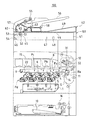
図1は、本発明の原稿読取り装置の第1実施形態を適用した画像形成装置を示す断面図である。この画像形成装置100は、原稿読取り装置101により読取られた原稿の画像又は外部から受信した画像をカラーもしくは単色で記録用紙に記録形成するものであり、レーザ露光装置1、現像装置2、感光体ドラム3、帯電器5、クリーナ装置4、中間転写ベルト装置8、定着装置12、用紙搬送経路S、給紙トレイ10、及び用紙排出トレイ15等により構成されている。
FIG. 1 is a cross-sectional view showing an image forming apparatus to which a first embodiment of a document reading apparatus according to the present invention is applied. The
画像形成装置100において扱われる画像データは、ブラック(K)、シアン(C)、マゼンタ(M)、イエロー(Y)の各色を用いたカラー画像に応じたもの、又は単色(例えばブラック)を用いたモノクロ画像に応じたものである。従って、現像装置2、感光体ドラム3、帯電器5、クリーナ装置4は各色に応じた4種類の潜像を形成するようにそれぞれ4個ずつ設けられ、それぞれがブラック、シアン、マゼンタ、及びイエローに対応付けられて、4つの画像ステーションPa、Pb、Pc、Pdが構成されている。
The image data handled in the
感光体ドラム3は、画像形成装置100のほぼ中央に配置されている。
The
帯電器5は、感光体ドラム3の表面を所定の電位に均一に帯電させるための帯電手段であり、接触型であるローラ型やブラシ型の帯電器のほか、チャージャー型の帯電器が用いられる。
The charger 5 is a charging means for uniformly charging the surface of the
レーザ露光装置1は、レーザダイオード及び反射ミラーを備えたレーザスキャニングユニット(LSU)であり、帯電された感光体ドラム3表面を画像データに応じて露光して、その表面に画像データに応じた静電潜像を形成する。
The laser exposure apparatus 1 is a laser scanning unit (LSU) provided with a laser diode and a reflection mirror, which exposes the surface of a charged
現像装置2は、感光体ドラム3上に形成された静電潜像を(K、C、M、Y)のトナーにより現像し、感光体ドラム3表面にトナー像を形成する。クリーナ装置4は、現像及び画像転写後に感光体ドラム3表面に残留したトナーを除去及び回収する。
The developing
感光体ドラム3の上方に配置されている中間転写ベルト装置8は、中間転写ベルト7、中間転写ベルト駆動ローラ21、従動ローラ22、中間転写ローラ6、及び中間転写ベルトクリーニング装置9を備えている。
The intermediate
中間転写ベルト駆動ローラ21、中間転写ローラ6、従動ローラ22等は、中間転写ベルト7を張架して支持し、中間転写ベルト7を矢印C方向に周回移動させる。
The intermediate transfer
中間転写ローラ6は、中間転写ベルト7近傍に回転可能に支持され、中間転写ベルト7を介して感光体ドラム3に圧接され、感光体ドラム3表面のトナー像を中間転写ベルト7に転写するための転写バイアスを印加されている。中間転写ローラ6は、直径8〜10mmの金属(例えばステンレス)軸をベースとし、その表面は、導電性の弾性材(例えばEPDM、発泡ウレタン等)により覆われているローラである。この導電性の弾性材により、記録用紙に対して均一に高電圧を印加することができる。
The
中間転写ベルト7は、各感光体ドラム3に接触するように設けられており、各感光体ドラム3表面のトナー像を中間転写ベルト7に順次重ねて転写することによって、カラーのトナー像(各色のトナー像)を形成する。この転写ベルトは、厚さ100μm〜150μm程度のフィルムを用いて無端ベルト状に形成されている。
The
上述の様に各感光体ドラム3表面のトナー像は、中間転写ベルト7で積層され、画像データによって示されるカラーのトナー像となる。このように積層された各色のトナー像は、中間転写ベルト7と共に搬送され、中間転写ベルト7と接触する2次転写装置11の転写ローラ11aによって記録用紙上に転写される。
As described above, the toner images on the surfaces of the respective
中間転写ベルト7と2次転写装置11の転写ローラ11aとは相互に圧接されて、ニップ域を形成する。また、2次転写装置11の転写ローラ11aには、中間転写ベルト7上の各色のトナー像を記録用紙に転写させるための電圧(トナーの帯電極性(−)とは逆極性(+)の高電圧)が印加される。さらに、そのニップ域を定常的に得るために、2次転写装置11の転写ローラ11aもしくは中間転写ベルト駆動ローラ21の何れか一方を硬質材料(金属等)とし、他方を弾性ローラ等の軟質材料(弾性ゴムローラ、または発泡性樹脂ローラ等)としている。
The
また、2次転写装置11によって中間転写ベルト7上のトナー像が記録用紙上に完全に転写されず、中間転写ベルト7上にトナーが残留することがあり、この残留トナーが次工程でトナーの混色を発生させる原因となる。このため、中間転写ベルトクリーニング装置9によって残留トナーを除去及び回収する。中間転写ベルトクリーニング装置9には、例えばクリーニング部材として、中間転写ベルト7に接触して残留トナーを除去するクリーニングブレードが設けられており、クリーニングブレードが接触する部位で、従動ローラ22により中間転写ベルト7裏側が支持されている。
In addition, the toner image on the
給紙トレイ10は、記録用紙を格納しておくためのトレイであり、画像形成装置100の下部に設けられて、トレイ内の記録用紙を供給する。
The
画像形成装置100には、給紙トレイ10から供給された記録用紙を2次転写装置11や定着装置12を経由させて用紙排出トレイ15に送るための、Sの字形状の用紙搬送経路Sが設けられている。この用紙搬送経路Sに沿って、用紙ピックアップローラ16、用紙レジストローラ14、定着装置12、及び記録用紙を搬送する搬送ローラ等が配置されている。
The
用紙ピックアップローラ16は、給紙トレイ10の端部に設けられ、給紙トレイ10から記録用紙を1枚ずつ用紙搬送経路Sに供給する呼び込みローラである。搬送ローラは、記録用紙の搬送を促進補助するための小型のローラであり、複数個設けられている。
The paper pick-up
用紙レジストローラ14は、搬送されて来た記録用紙を一旦停止させて、記録用紙の先端を揃え、中間転写ベルト7と2次転写装置11の転写ローラ11a間のニップ域で中間転写ベルト7上のカラーのトナー像が記録用紙に転写されるように、感光体ドラム3及び中間転写ベルト7の回転にあわせて、記録用紙をタイミングよく搬送する。
The
例えば、用紙レジストローラ14は、図示しないレジスト前検知スイッチの検出出力に基づき、中間転写ベルト7と2次転写装置11の転写ローラ11a間のニップ域で中間転写ベルト7上のカラーのトナー像の先端が記録用紙の画像形成領域の先端に合うように、記録用紙を搬送する。
For example, the
定着装置12は、加熱ローラ31及び加圧ローラ32等を備えている。加熱ローラ31及び加圧ローラ32は、中間転写ベルト7と2次転写装置11の転写ローラ11a間のニップ域を通過して来た記録用紙を挟み込んで搬送する。
The fixing
加熱ローラ31は、図示しない温度検出器の検出出力に基づき、制御部によって所定の定着温度となるように制御されており、加圧ローラ32とともに記録用紙を熱圧着することにより、記録用紙に転写されたトナー像を溶融、混合、圧接し、記録用紙に対して熱定着させる機能を有している。
The
各色のトナー像の定着後の記録用紙は、搬送ローラによって用紙排出トレイ15上にフェイスダウンで排出される。
The recording paper after the fixing of the toner images of the respective colors is discharged face down onto the
次に、図1の画像形成装置100上に搭載された第1実施形態の原稿読取り装置101を説明する。第1実施形態の原稿読取り装置101は、その上側に配置された原稿搬送部42により搬送されている原稿画像を読取ることができる。
Next, the
原稿搬送部42は、その奥の一辺をヒンジ(図示せず)により下側の原稿読取り装置101の一辺に枢支され、その手前部分を上下させることにより開閉される。原稿搬送部42を開いたときには、原稿読取り装置101のプラテンガラス44が開放され、このプラテンガラス44上に原稿が載置される。
The
原稿読取り装置101は、プラテンガラス44、第1走査ユニット45、第2走査ユニット46、結像レンズ47、及びCCD(Charge Coupled Device)48等を備えている。
The
第1走査ユニット45は、露光走査ユニットとも称され、光源51、及び第1反射ミラー52を備えており、副走査方向へと原稿サイズに応じた距離だけ一定速度Vで移動しながら、プラテンガラス44上の原稿を光源51によって露光し、その反射光を第1反射ミラー52により反射して第2走査ユニット46へと導き、これにより原稿の表面の画像を副走査方向に走査する。
The
第2走査ユニット46は、第2及び第3反射ミラー53、54を備えており、第1走査ユニット45に追従して速度V/2で移動しつつ、原稿の反射光を第2及び第3反射ミラー53、54により反射して結像レンズ47へと導く。
The
結像レンズ47は、原稿の反射光をCCD48に集光して、原稿の画像をCCD48上に結像させる。CCD48は、原稿画像を繰り返し主走査方向に走査し、1主走査の度に、1主走査ラインのアナログ画像信号を出力する。
The
第1及び第2走査ユニット45、46の端部には、それぞれのプーリー(図示せず)を設けており、これらのプーリーにワイヤー(図示せず)を架け渡し、このワイヤーをステッピングモータにより駆動して、第1及び第2走査ユニット45、46を同期移動させている。
Pulleys (not shown) are provided at the ends of the first and
また、原稿読取り装置101は、静止原稿だけではなく、原稿搬送部42により搬送されている原稿表面の画像を読取ることができる。この場合は、読取りガラス板65の下方に第1及び第2走査ユニット45、46を位置決めし、この状態で、原稿搬送部42による原稿の搬送を開始する。
The
原稿搬送部42では、ピックアップローラ55を原稿トレイ56上の原稿に押し当て回転させて、原稿を引き出し、原稿を原稿搬送路57に沿って搬送し、原稿の先端を原稿レジストローラ62に突き当てて揃え、原稿を原稿読取り装置101の読取りガラス板65上に通過させ、更に原稿を原稿搬送ローラ63及び排紙ローラ58により搬送して排紙トレイ49へと排出する。
In the
この原稿の搬送に際し、第1走査ユニット45の光源51により原稿表面を読取りガラス板65を介して照明し、原稿表面からの反射光を第1及び第2走行ユニット45、46の第1乃至第3反射ミラー52〜54により結像レンズ47へと導き、原稿表面からの反射光を結像レンズ47によりCCD48に集光させ、原稿の画像をCCD48上に結像させ、CCD48により原稿画像を読取る。
When the document is transported, the
このようにCCD48により原稿画像が読取られ、この原稿画像を示すアナログ画像信号がCCD48から出力される。そして、このアナログ画像信号がデジタルの画像データにA/D変換され、この画像データが種々の画像処理を経て画像形成装置100のレーザ露光装置1へと送受され、この画像データに応じて感光体ドラム3表面が露光され、感光体ドラム3表面の静電潜像の形成、静電潜像の現像、トナー像の転写等がなされて、画像形成装置100において画像が記録用紙に記録される。
In this way, the original image is read by the
次に、第1実施形態の原稿読取り装置101の構造を説明する。図2は、原稿読取り装置101を示す斜視図である。
Next, the structure of the
図2に示すように暗筐体70の上側の開口部には、プラテンガラス44及び読取りガラス板65が設けられている。プラテンガラス44の下方には、第1走査ユニット45、第2走査ユニット46(図示されず)、結像レンズ47、及びCCD48が配置されている。第1及び第2走査ユニット45、46の両端は、暗筐体70の両側壁70aで滑動自在に支持されており、先に述べたようにプーリー、ワイヤー、及びステッピングモータにより駆動されて、第1及び第2走査ユニット45、46が同期移動される。
As shown in FIG. 2, a
プラテンガラス44上の原稿が読取られるときには、プラテンガラス44下方で第1及び第2走査ユニット45、46が同期移動されつつ、光源51(図1に示す)によって原稿が露光され、その反射光が第1乃至第3反射ミラー52〜54(図1に示す)で反射され、結像レンズ47を通じてCCD48に集光され、CCD48により原稿画像が読取られる。
When the original on the
また、読取りガラス65上を通過する原稿が読取られるときには、読取りガラス板65の下方に第1及び第2走査ユニット45、46が位置決めされ、光源51によって原稿が露光され、その反射光が第1乃至第3反射ミラー52〜54で反射され、結像レンズ47を通じてCCD48に集光され、CCD48により原稿画像が読取られる。
When a document passing over the reading
ここで、第1走査ユニット45の第1反射ミラー52は、プラテンガラス44及び読取りガラス65上の原稿近くにあるため、この第1反射ミラー52に埃等が付着すると、これが読取られた原稿画像上でスジ等となって現れ、画像品質が劣化する。
Here, since the
このため、第1走査ユニット45の第1反射ミラー52が汚れたときには、プラテンガラス44を取り外して、第1反射ミラー52を清掃する必要がある。
For this reason, when the
ところが、第1走査ユニット45の第1反射ミラー52の上部には、上方の原稿からの反射光を選択的に通過させかつ外乱光や迷光を遮断する狭いスリットStが存在するため、第1反射ミラー52の清掃が容易ではない。
However, a narrow slit St that selectively allows the reflected light from the upper document to pass through and blocks disturbance light and stray light is present above the first reflecting
そこで、第1実施形態の原稿読取り装置101では、第1走査ユニット45を図3(a)、(b)及び図4(a)、(b)に示すような構造にして、第1走査ユニット45の第1反射ミラー52の清掃を容易にしている。
Therefore, in the
図3(a)、(b)は、第1走査ユニット45を示す斜視図及び分解斜視図である。また、図4(a)、(b)は、図3(a)、(b)に対応するそれぞれの断面図である。
3A and 3B are a perspective view and an exploded perspective view showing the
図3(a)、(b)及び図4(a)、(b)から明らかなように、第1走査ユニット45は、移動走査フレーム71と、移動走査フレーム71上に着脱自在に搭載される光源用フレーム72とを備えている。
As is clear from FIGS. 3A, 3B and FIGS. 4A, 4B, the
移動走査フレーム71は、副走査方向に移動走査されるものであって、その両端71aが暗筐体70の両側壁で滑動自在に支持され、先に述べたようにプーリー、ワイヤー、及びステッピングモータにより駆動される。また、移動走査フレーム71には、第1反射ミラー52が設けられており、この第1反射ミラー52が副走査方向と直交する主走査方向に沿ってかつ副走査方向に対して45°傾斜して配置されている。
The moving
移動走査フレーム71の前端部71bが上側に折れ曲がり、この前端部71bに開口スリット71cが形成されている。また、移動走査フレーム71の隔壁部79よりも後部には回路ユニット73が搭載されている。第1反射ミラー52は、移動走査フレーム71の前端部71bと隔壁部79間に配置されており、前端部71bと隔壁部79間の開口部74の幅が十分に広く設定されている。
A
光源用フレーム72は、原稿の照明等を行うものであって、主走査方向に延びるスリットStが形成されたスリット部75を有している。このスリット部75の長手方向両側には、相互に平行な細長い形状の各基板76が配置されている。これらの基板76には、図1の光源51となる複数のLED77が一列にそれぞれ配列されており、各LED77がそれぞれの基板76の配線パターンに接続され、各基板76の配線パターンがハーネス(図示せず)を通じて移動走査フレーム71の回路ユニット73に接続されている。移動走査フレーム71の回路ユニット73からハーネス及び各基板76の配線パターンを通じて各LED77へと電力が供給され、各LED77が点灯する。尚、各LED77は、発光素子の1つであるが、光源51として、他の種類の発光素子を適用してもよい。
The
光源用フレーム72には2個の孔72aが形成されており、光源用フレーム72を移動走査フレーム71上に載せ、2本のネジ78を光源用フレーム72の各孔72aを通じて移動走査フレーム71の各ネジ孔(図示せず)にねじ込んで、光源用フレーム72を移動走査フレーム71上に固定配置する。
Two
図3(a)及び図4(a)に示すように光源用フレーム72を移動走査フレーム71上に固定配置した状態では、光源用フレーム72のスリット部75のスリットStの直下に第1反射ミラー52が位置決めされる。各基板76の各LED77が発光すると、各LED77の光が上方に出射されてプラテンガラス44又は読取りガラス65を通じて原稿に照射され、原稿からの反射光がプラテンガラス44又は読取りガラス65を通じてスリットStに入射し、この反射光がスリットStを通じて第1反射ミラー52に入射して反射され、この反射光が移動走査フレーム71の前端部71bの開口スリット71cを通じて第2走査ユニット46の第2反射ミラー53へと出射される。
As shown in FIGS. 3A and 4A, in the state where the
ここで、第1走査ユニット45の第1反射ミラー52が汚れても、狭いスリットStを通じて第1反射ミラー52を清掃することが容易ではないのは明らかである。
Here, even if the
そこで、移動走査フレーム71上の第1反射ミラー52を清掃するときには、プラテンガラス44を取り外し、図3(b)及び図4(b)に示すように2本のネジ78を取り外して、光源用フレーム72を移動走査フレーム71から持ち上げて離間させる。
Therefore, when cleaning the first reflecting
この状態では、第1反射ミラー52の上方にスリットStが存在せず、また移動走査フレーム71上の前端部71bと隔壁部79間の開口部74の幅がスリットStの幅よりも十分に広いことから、この開口部74の内側に配置された第1反射ミラー52を容易に清掃することができる。
In this state, the slit St does not exist above the
更に、この清掃に際しては、第1走査ユニット45を取り外す必要がなく、第1走査ユニット45の位置ずれが生じないので、その位置調整を行う必要がない。
Further, in this cleaning, it is not necessary to remove the
図5(a)、(b)は、第2実施形態の原稿読取り装置101における第1走査ユニット(露光走査ユニットとも称す)を示す斜視図及び分解斜視図である。また、図6(a)、(b)は、図5(a)、(b)に対応するそれぞれの断面図である。尚、図5及び図6において、図3及び図4と同様の作用を果たす部位には同じ符号を付している。
5A and 5B are a perspective view and an exploded perspective view showing a first scanning unit (also referred to as an exposure scanning unit) in the
第2実施形態における第1走査ユニット45Aでは、図3及び図4における光源用フレーム72の代わりに、光源用フレーム72Aを適用している。
In the
この光源用フレーム72Aは、主走査方向に延びるスリットStが形成されたスリット部75を有しており、このスリットStの長手方向両側に、図1の光源51となる相互に平行な細長い形状の各導光体81が配置されている。
The
各導光体81は、図7に示すように長く延びる帯状の透光体であり、原稿と対向する上側面が光出射面81bとなっている。各導光体81の長手方向の一端面(先端面)が光入射面81aとなっており、各導光体81の光入射面81aにそれぞれのLED82が対向配置されている。これらLED82の光は、光入射面81aから導光体81に入射し、導光体81の光出射面81bから出射される。
As shown in FIG. 7, each
導光体81の裏面81cは、光出射面81bに対して傾斜しており、導光体81の後端に近づくに従って裏面81cが光出射面81bに近づき、導光体81がテーパー形状となっている。この導光体81の裏面81cは、光を光出射面81bに向けて反射する拡散反射面(プリズム面)となっている。このような形状及び構造により、導光体81の光出射面81b全体から均一な光が出射される。
The
このような光源用フレーム72Aも、図3及び図4の光源用フレーム72と同様に、移動走査フレーム71上に載せられる。そして、2本のネジ(図示せず)を光源用フレーム72Aの各孔(図示せず)を通じて移動走査フレーム71の各ネジ孔(図示せず)にねじ込んで、光源用フレーム72Aを移動走査フレーム71上に固定配置する。
Such a
図5(a)及び図6(a)に示すように光源用フレーム72Aを移動走査フレーム71上に固定配置した状態では、光源用フレーム72Aのスリット部75のスリットStの直下に第1反射ミラー52が位置決めされる。
As shown in FIGS. 5A and 6A, in a state where the
各導光体81の上側を向くそれぞれの光出射面81bから出射された光は、プラテンガラス44又は読取りガラス65を通じて原稿に照射され、原稿からの反射光がプラテンガラス44又は読取りガラス65を通じてスリットStに入射し、この反射光がスリットStを通じて第1反射ミラー52に入射する。
The light emitted from the respective
移動走査フレーム71上の第1反射ミラー52を清掃するときには、プラテンガラス44を取り外し、図5(b)及び図6(b)に示すように2本のネジを取り外して、光源用フレーム72Aを移動走査フレーム71から持ち上げて離間させる。このとき、第1反射ミラー52の上方にスリットStが存在せず、また移動走査フレーム71上の前端部71bと各壁部79間の開口部74の幅がスリットStの幅よりも十分に広いことから、この開口部74の内側に配置された第1反射ミラー52を容易に清掃することができる。
When cleaning the first reflecting
以上、添付図面を参照しながら本発明の好適な実施形態について説明したが、本発明は係る例に限定されないことは言うまでもない。当業者であれば、特許請求の範囲に記載された範疇内において、各種の変更例または修正例に想到し得ることは明らかであり、それらについても当然に本発明の技術的範囲に属するものと解される。 As mentioned above, although preferred embodiment of this invention was described referring an accompanying drawing, it cannot be overemphasized that this invention is not limited to the example which concerns. It will be apparent to those skilled in the art that various changes and modifications can be made within the scope of the claims, and these are naturally within the technical scope of the present invention. It is understood.
例えば、上記各実施形態では、光源として、複数のLEDの列及び帯状の導光体を例示しているが、キセノンランプ、ハロゲンランプ、蛍光灯等を適用してもよい。 For example, in each of the above embodiments, a plurality of LED rows and a strip-shaped light guide are illustrated as the light source, but a xenon lamp, a halogen lamp, a fluorescent lamp, or the like may be applied.
1 レーザ露光装置
2 現像装置
3 感光体ドラム
4 クリーナ装置
5 帯電器
8 中間転写ベルト装置
10 給紙トレイ
11 2次転写装置
12 定着装置
44 プラテンガラス
45、45A 第1走査ユニット
46 第2走査ユニット
47 結像レンズ
48 CCD(Charge Coupled Device)
51 光源
52 第1反射ミラー
53 第2反射ミラー
54 第3反射ミラー
65 読取りガラス板
71 移動走査フレーム
72、72A 光源用フレーム
73 回路ユニット
74 開口部
75 スリット部
76 基板
77、82 LED
81 導光体
100 画像形成装置
101 原稿読取り装置
DESCRIPTION OF SYMBOLS 1
51
81
Claims (6)
前記露光走査手段は、移動可能に支持された移動走査部と、この移動走査部上に着脱可能に支持された照明部とを備え、
前記照明部は、前記原稿を透明な原稿載置板を介して露光をする光源と、該原稿からの反射光を前記移動走査部へと通過させるスリットとを有し、
前記移動走査部は、前記スリットを通過して来た反射光を反射するミラーを有することを特徴とする原稿読取り装置。 In a document reading apparatus provided with an exposure scanning unit provided below a transparent document placing plate on which a document is placed and moved in the scanning direction while exposing the document through the transparent document placing plate.
The exposure scanning means includes a movable scanning unit supported movably, and an illumination unit supported detachably on the movable scanning unit,
The illumination unit includes a light source that exposes the document through a transparent document placing plate, and a slit that allows reflected light from the document to pass to the moving scanning unit,
The document reading apparatus, wherein the moving scanning unit includes a mirror that reflects the reflected light that has passed through the slit.
前記各導光体は、前記各発光素子から入射した光を導いて、該各導光体の側壁から前記原稿へと光を出射することを特徴とする請求項1に記載の原稿読取り装置。 The light source includes light guides disposed on both sides in the longitudinal direction of the slit and in parallel with each other, and light emitting elements that allow light to enter one end of the light guides,
2. The document reading apparatus according to claim 1, wherein each of the light guides guides light incident from each of the light emitting elements and emits light from a side wall of each of the light guides to the document.
Priority Applications (1)
| Application Number | Priority Date | Filing Date | Title |
|---|---|---|---|
| JP2008320038A JP2010147592A (en) | 2008-12-16 | 2008-12-16 | Original reader and image forming apparatus equipped with the same |
Applications Claiming Priority (1)
| Application Number | Priority Date | Filing Date | Title |
|---|---|---|---|
| JP2008320038A JP2010147592A (en) | 2008-12-16 | 2008-12-16 | Original reader and image forming apparatus equipped with the same |
Publications (1)
| Publication Number | Publication Date |
|---|---|
| JP2010147592A true JP2010147592A (en) | 2010-07-01 |
Family
ID=42567594
Family Applications (1)
| Application Number | Title | Priority Date | Filing Date |
|---|---|---|---|
| JP2008320038A Pending JP2010147592A (en) | 2008-12-16 | 2008-12-16 | Original reader and image forming apparatus equipped with the same |
Country Status (1)
| Country | Link |
|---|---|
| JP (1) | JP2010147592A (en) |
Cited By (3)
| Publication number | Priority date | Publication date | Assignee | Title |
|---|---|---|---|---|
| WO2013118414A1 (en) * | 2012-02-07 | 2013-08-15 | 三菱電機株式会社 | Light-source device and reflector-support structure |
| JP2014007464A (en) * | 2012-06-21 | 2014-01-16 | Mitsubishi Electric Corp | Light source device and reflector plate support structure |
| CN109040509A (en) * | 2017-06-09 | 2018-12-18 | 精工爱普生株式会社 | The generation method of scanner, scan data |
-
2008
- 2008-12-16 JP JP2008320038A patent/JP2010147592A/en active Pending
Cited By (5)
| Publication number | Priority date | Publication date | Assignee | Title |
|---|---|---|---|---|
| WO2013118414A1 (en) * | 2012-02-07 | 2013-08-15 | 三菱電機株式会社 | Light-source device and reflector-support structure |
| CN104094045A (en) * | 2012-02-07 | 2014-10-08 | 三菱电机株式会社 | Light-source device and reflector-support structure |
| US9151465B2 (en) | 2012-02-07 | 2015-10-06 | Mitsubishi Electric Corporation | Light-source device and reflector-support structure |
| JP2014007464A (en) * | 2012-06-21 | 2014-01-16 | Mitsubishi Electric Corp | Light source device and reflector plate support structure |
| CN109040509A (en) * | 2017-06-09 | 2018-12-18 | 精工爱普生株式会社 | The generation method of scanner, scan data |
Similar Documents
| Publication | Publication Date | Title |
|---|---|---|
| US10412254B2 (en) | Illuminating device, image reading apparatus and image forming apparatus | |
| JP4889766B2 (en) | Image reading apparatus and image forming apparatus having the same | |
| JP4757340B2 (en) | Illumination apparatus, image reading apparatus including the illumination apparatus, and image forming apparatus including the image reading apparatus | |
| JP2019032482A (en) | Lens mirror array and image forming apparatus | |
| JP2009204668A (en) | Image forming apparatus | |
| JP5860854B2 (en) | Image reading apparatus and image forming apparatus having the same | |
| JP2010147592A (en) | Original reader and image forming apparatus equipped with the same | |
| AU2010201057B2 (en) | Image reading device and image forming apparatus | |
| JP2012054834A (en) | Image reader and image formation apparatus with the same | |
| JP4920088B2 (en) | Illumination apparatus, image reading apparatus including the illumination apparatus, and image forming apparatus including the image reading apparatus | |
| US8599447B2 (en) | Illuminating apparatus, image reading apparatus, and image forming apparatus | |
| JP6140790B2 (en) | Image reading apparatus and image forming apparatus having the same | |
| JP2013164964A (en) | Neutralization apparatus, and image forming apparatus including the same | |
| JP2010210749A (en) | Image reader and image forming apparatus | |
| JP2009166247A (en) | Laser exposure system and image forming apparatus | |
| JP5408537B2 (en) | Image reading apparatus and image forming apparatus | |
| JP6140791B2 (en) | Image reading apparatus and image forming apparatus having the same | |
| JPH11327384A (en) | Image forming device and image forming method | |
| JP2010063005A (en) | Automatic document reading apparatus, and image forming apparatus including the same | |
| JP2003015390A (en) | Image forming device | |
| JP2007147892A (en) | Original document reader | |
| JP2019046556A (en) | Illumination device, drum unit, image forming device equipped with illumination device, and image reading device | |
| JP2006148281A (en) | Image reading apparatus | |
| JP2012156574A (en) | Image reading device and image forming device comprising the same |