JP2010146923A - Lighting system - Google Patents
Lighting system Download PDFInfo
- Publication number
- JP2010146923A JP2010146923A JP2008324633A JP2008324633A JP2010146923A JP 2010146923 A JP2010146923 A JP 2010146923A JP 2008324633 A JP2008324633 A JP 2008324633A JP 2008324633 A JP2008324633 A JP 2008324633A JP 2010146923 A JP2010146923 A JP 2010146923A
- Authority
- JP
- Japan
- Prior art keywords
- lighting
- task
- control
- human
- control unit
- Prior art date
- Legal status (The legal status is an assumption and is not a legal conclusion. Google has not performed a legal analysis and makes no representation as to the accuracy of the status listed.)
- Pending
Links
Images

Classifications
-
- Y—GENERAL TAGGING OF NEW TECHNOLOGICAL DEVELOPMENTS; GENERAL TAGGING OF CROSS-SECTIONAL TECHNOLOGIES SPANNING OVER SEVERAL SECTIONS OF THE IPC; TECHNICAL SUBJECTS COVERED BY FORMER USPC CROSS-REFERENCE ART COLLECTIONS [XRACs] AND DIGESTS
- Y02—TECHNOLOGIES OR APPLICATIONS FOR MITIGATION OR ADAPTATION AGAINST CLIMATE CHANGE
- Y02B—CLIMATE CHANGE MITIGATION TECHNOLOGIES RELATED TO BUILDINGS, e.g. HOUSING, HOUSE APPLIANCES OR RELATED END-USER APPLICATIONS
- Y02B20/00—Energy efficient lighting technologies, e.g. halogen lamps or gas discharge lamps
- Y02B20/40—Control techniques providing energy savings, e.g. smart controller or presence detection
Landscapes
- Circuit Arrangement For Electric Light Sources In General (AREA)
Abstract
Description
本発明は、人感センサの検出結果に基づいて、照明器具と、タスク灯との調光制御が可能な制御部を有する照明システムに関する。 The present invention relates to a lighting system having a control unit capable of dimming control between a lighting fixture and a task lamp based on a detection result of a human sensor.
従来より、各種作業を行う机の上面に対し所定の照射範囲内で照明光を照射するタスク灯を各机毎に設け、作業時に各作業者が必要に応じてそのタスク灯を点灯させることができる照明システムが広く普及している。 Conventionally, a task lamp that irradiates illumination light within a predetermined irradiation range on the upper surface of a desk that performs various tasks is provided for each desk, and each worker can turn on the task lamp as needed during work. Lighting systems that can be used are widespread.
このような照明システムには、タスク灯の消し忘れを防止して省エネを図るという観点から、人感センサをタスク灯近傍に設け、この人感センサで検知した場合にのみ点灯し、又は、タイマで設定した時間だけ点灯するようにしたものがある。 In such a lighting system, from the viewpoint of saving energy by preventing the task lamp from being turned off, a human sensor is provided in the vicinity of the task lamp and lights only when it is detected by the human sensor, or a timer is used. There is one that lights up only for the time set in.
ところが、このような照明システムは、机での作業を行わない人が机の近くを通り過ぎたり、机の近傍に人が集まった場合等に人感センサに検知されてタスク灯が点灯する場合があり、省エネという目的に反する場合もある。 However, in such a lighting system, when a person who does not work on the desk passes by the desk or when people gather near the desk, the task light may be detected by the human sensor. Yes, it may be contrary to the purpose of energy saving.
そこで、作業者が点灯させたい場合のみタスク灯を点灯させることができ、且つ、タスク灯の消し忘れを確実に防止できることを目的として、例えば特許文献1に記載の照明装置が提案されている。 Therefore, for example, a lighting device described in Patent Document 1 has been proposed in order to turn on the task lamp only when the operator wants to turn it on and to reliably prevent the task lamp from being forgotten to be turned off.
この特許文献1には、机の上面を照射するタスク灯と、各机毎に設けられ、作業者が携帯するIDカードを検知するカードリーダと、このカードリーダからのIDカードのセットの有無を示す検知信号に基づき、タスク灯を点灯又は消灯させる制御手段とを有する照明装置に関する技術が開示されている。
一般に、タスク灯が設けられた机は、建物内の室内に配置され、この室内の例えば天井には複数の照明器具が配設されている。これら複数の照明器具は、通常、センタ装置(中央処理装置ともいう)によって調光が制御されるようになっている。 Generally, a desk provided with a task lamp is arranged in a room in a building, and a plurality of lighting fixtures are arranged on the ceiling, for example, in the room. In the plurality of lighting fixtures, dimming is usually controlled by a center device (also referred to as a central processing unit).
このような複数の照明器具及びセンタ装置を有する照明システムは、前記特許文献1に記載の照明装置とは別々の構成で設けられている。このため、これらの照明装置は、夫々の調光が別々に制御されており、また、作業者による操作によって夫々の光量を必要に応じて個々に低くすることにより、全体の照明電力を低減するようにしていた。 Such a lighting system having a plurality of lighting fixtures and a center device is provided in a configuration different from that of the lighting device described in Patent Document 1. For this reason, each lighting control of these lighting devices is controlled separately, and the overall illumination power is reduced by individually reducing the respective light amounts as required by the operation of the operator. It was like that.
しかしながら、このような従来技術では、前記特許文献1に記載の照明装置を用いたとしても、この照明装置のタスク灯の調光制御に関連づけて、前記複数の照明器具の調光制御を行うことができないため、室内全体の照明による消費電力の省エネルギー化を図ることができないといった問題点があった。 However, in such a conventional technique, even if the lighting device described in Patent Document 1 is used, the dimming control of the plurality of lighting fixtures is performed in association with the dimming control of the task lamp of the lighting device. Therefore, there is a problem that it is not possible to save power consumption by lighting the entire room.
そこで、本発明は前記問題点に鑑みてなされたもので、室内全体の照明電力の省エネルギー化を図ることができる照明システムを提供することを目的とする。 Therefore, the present invention has been made in view of the above problems, and an object of the present invention is to provide an illumination system that can save energy in the illumination power of the entire room.
本発明の請求項1に係る照明システムは、天井面に配設される照明器具と; 机の上面の所定の照射範囲に照明光を照射するためのタスク灯と;前記照射範囲に対応する範囲内の人の有無を検出する人感センサと;前記照明器具及び前記タスク灯に、調光を制御するための制御信号の伝送が可能であり、前記人感センサの検出結果に基づいて、前記照明器具及び前記タスク灯の調光を制御する制御部と;を具備している。 A lighting system according to claim 1 of the present invention includes: a lighting fixture disposed on a ceiling surface; a task lamp for irradiating illumination light to a predetermined irradiation range on the upper surface of a desk; a range corresponding to the irradiation range A human sensor for detecting the presence or absence of a person in the vehicle; a control signal for controlling light control can be transmitted to the lighting fixture and the task lamp, and based on the detection result of the human sensor, A lighting unit and a control unit for controlling dimming of the task lamp.
請求項1において、タスク灯は、机、又はその机を包囲するパーテーションなどに設置され、照明光を照射する、例えばランプ又はLEDで構成された照明部を有している。このタスク灯は、各机毎に設けられて設置しても良い。 In claim 1, the task lamp is installed on a desk, a partition surrounding the desk, or the like, and has an illuminating unit configured to irradiate illumination light, such as a lamp or an LED. This task light may be provided for each desk.
また、タスク灯の調光制御は、通常、点灯又は消灯となるように制御されるが、照度の変更制御が可能であっても良い。 In addition, the dimming control of the task lamp is normally controlled so as to be turned on or off, but the illumination intensity may be changed.
人感センサは、前記照明範囲に対応する範囲内の人の有無を検出できる構成であれば、どのような構成であっても良い。例えば、赤外線を照射してその反射結果を用いて人の有無を検出する赤外線方式の人感センサであってもよいし、人体から発する赤外線の動きを検出する構成であってもよい。 The human sensor may have any configuration as long as it can detect the presence or absence of a person within the range corresponding to the illumination range. For example, it may be an infrared human sensor that irradiates infrared rays and detects the presence or absence of a person using the reflection result, or may be configured to detect the movement of infrared rays emitted from a human body.
制御部は、例えば中央処理装置としてのセンタ装置であり、照明器具及びタスク灯の調光制御を行うCPU等の制御部を有している。 The control unit is, for example, a center device as a central processing unit, and includes a control unit such as a CPU that performs dimming control of a lighting fixture and a task lamp.
また、室内の照明電力の省エネルギー化を図るための照明器具の調光制御は、例えば、人感センサの検出結果が人有りと判断した場合、全点灯状態から調光状態へ制御する。このとき、机上面照度は例えば700ルクスから350ルクスに落とすように制御してもよい。勿論、照明器具の明るさは規格内で設定されるが、700ルクス及び350ルクスに限定されることはなく、適宜変更設定が可能である。
人感センサの検出結果は例えば有線または無線等の伝送手段によって制御部に伝送してもよい。
In addition, the dimming control of the lighting fixture for energy saving of indoor lighting power is controlled from the fully lit state to the dimming state, for example, when the detection result of the human sensor is determined to be present. At this time, the illuminance on the desk surface may be controlled to drop from 700 lux to 350 lux, for example. Of course, the brightness of the luminaire is set within the standard, but is not limited to 700 lux and 350 lux, and can be appropriately changed.
The detection result of the human sensor may be transmitted to the control unit by transmission means such as wired or wireless.
本発明の請求項2に係る照明システムは、請求項1に記載の照明システムにおいて、前記人感センサの出力信号は、前記制御部に無線伝送されることを特徴とする。
The illumination system according to
無線伝送の伝送媒体としては、例えば赤外線、無線等の無線通信手段を用いることができる。 As a transmission medium for wireless transmission, for example, wireless communication means such as infrared or wireless can be used.
本発明の請求項3に係る照明システムは、請求項1または2に記載の照明システムにおいて、前記タスク灯は、床下配線によって前記制御部に接続されることを特徴とする。 The lighting system according to a third aspect of the present invention is the lighting system according to the first or second aspect, wherein the task lamp is connected to the control unit by underfloor wiring.
本発明の請求項4に係る照明システムは、請求項1から請求項3の何れか1項に記載の照明システムにおいて、前記照明器具は複数配設され、前記タスク灯及び前記人感センサは夫々対応させて複数設けられ、前記制御部は、予め設定されたグループの人感センサの内、人を検出した人感センサ数に応じて、この人を検出した人感センサに対応した前記タスク灯を照明する領域に対応する前記照明器具の明るさを変更するように調光制御することを特徴とする。 A lighting system according to a fourth aspect of the present invention is the lighting system according to any one of the first to third aspects, wherein a plurality of the lighting fixtures are provided, and the task lamp and the human sensor are respectively provided. The control unit is provided in correspondence with each other, and the control unit corresponds to the number of human sensors that have detected a person among the human sensors in a preset group, and the task lamp corresponding to the human sensor that has detected the person The dimming control is performed so as to change the brightness of the luminaire corresponding to the region where the light is illuminated.
タスク灯と人感センサは、例えば夫々1:1で対応させてもよいし、人感センサがタスク灯に取り付けられた構成でもよい。また、1つの人感センサを複数のタスク灯毎にグループ化してもよい。勿論、1つのタスク灯と複数の人感センサとをグループ化しても良い。 For example, the task light and the human sensor may correspond to each other in a 1: 1 ratio, or the human sensor may be attached to the task light. Further, one human sensor may be grouped for each of a plurality of task lights. Of course, one task light and a plurality of human sensors may be grouped.
請求項1の本発明によれば、室内全体の照明電力の省エネルギー化を図ることができる照明システムを提供することが可能となる。 According to the first aspect of the present invention, it is possible to provide an illumination system that can save energy in the illumination power of the entire room.
請求項2の発明によれば、請求項1の発明と同様の効果を得る他に、前記人感センサの出力信号は、前記制御部に無線伝送されるので、煩わしい配線を行わなくても、照明器具の調光制御が可能となる。
According to the invention of
請求項3の発明によれば、請求項1または2の発明と同様の効果を得る他に、前記タスク灯は、床下配線によって前記制御部に接続されることより、従来、机上でタスク灯の調光制御を行うのに必要な操作手段やカードリーダ及び制御手段等を机上に設置しなくても、制御部によってタスク灯の調光制御が行うことができ、また、室内のスペースを有効利用することも可能である。
According to the invention of claim 3, in addition to obtaining the same effect as that of the invention of
請求項4の本発明によれば、さらに、室内の照明電力の省エネルギー効果を向上できるといった効果を得る。 According to the fourth aspect of the present invention, the effect of improving the energy saving effect of indoor lighting power can be obtained.
以下、図面を参照して本発明の実施の形態を説明する。
(第1の実施の形態)
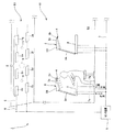
図1から図3は本発明の照明システムの第1の実施の形態に係り、図1は室内に配設された照明システム全体の概略構成を示す全体構成図、図2は図1に示す照明システムの電気的な構成を示すブロック図、図3は本実施の形態の照明システムの作用を説明するためのフローチャートである。
Embodiments of the present invention will be described below with reference to the drawings.
(First embodiment)
1 to 3 relate to a first embodiment of an illumination system according to the present invention. FIG. 1 is an overall configuration diagram showing a schematic configuration of the entire illumination system disposed in a room. FIG. 2 is an illumination shown in FIG. A block diagram showing the electrical configuration of the system, FIG. 3 is a flowchart for explaining the operation of the illumination system of the present embodiment.
図1に示すように、本実施の形態に係る照明システム1は、複数の照明器具2(2a、2b、2c…)と、複数のタスク灯3(3a、3b…)と、複数の人感センサ4(4a、4b…)と、制御部を構成するセンタ装置5とを有して構成されている。 As shown in FIG. 1, the lighting system 1 according to the present embodiment includes a plurality of lighting fixtures 2 (2a, 2b, 2c...), A plurality of task lights 3 (3a, 3b...), And a plurality of human feelings. The sensor 4 (4a, 4b ...) and the center apparatus 5 which comprises a control part are comprised.
照明器具2は、複数の照明器具2a、2b、2c…を有して構成される。そして、これら複数の照明器具2a、2b、2c…は、室内50の例えば天井面51に配設される。
The
また、これら複数の照明器具2a、2b、2c…は、図1及び図2に示すように、伝送線6を介してセンタ装置5に、調光用の制御信号を受信できるように接続されている。
尚、複数の照明器具2a、2b、2c…は、天井面51の他にも、壁等に配設しても良く、室内50全体を照明する照明器具として配設されたものであれば良い。
Further, as shown in FIGS. 1 and 2, the plurality of
In addition to the
また、これら複数の照明器具2a、2b、2c…は、図2に示すように、夫々交流電源10からの電力が供給されており、各照明器具2a、2b、2c…の調光は、センタ装置5から伝送される制御信号によって制御される。
Further, as shown in FIG. 2, the plurality of
室内50には、作業用の机8が複数配設されている。そして、これら複数の各机8には、それぞれタスク灯3(3a、3b…)が設置されている。
タスク灯3は、机8の上面に所定の照射範囲で照明光を照射するものである。尚、タスク灯3は、机8に設置するタイプである場合には、一端が机8に固定されたアーム3Aと、このアーム3Aの他端に取り付けられた照明部3Bとを有して構成され、この照明部3Bは、照明光を照射する図示しない光源を有して構成されている。
A plurality of work desks 8 are arranged in the
The task lamp 3 irradiates the upper surface of the desk 8 with illumination light within a predetermined irradiation range. When the task lamp 3 is a type installed on the desk 8, the task lamp 3 includes an
勿論、タスク灯3は、机8に設置するタイプに限定されるものではなく、例えば机8を囲む図示しないパーテーションに取り付けるタイプのものであっても良い。また、照明部3Bの光源は、通常のランプ、又はLED等を用いて構成されている。 Of course, the task lamp 3 is not limited to the type installed on the desk 8 but may be of a type attached to a partition (not shown) surrounding the desk 8, for example. Moreover, the light source of the illumination part 3B is comprised using the normal lamp | ramp or LED.
このような構成のタスク灯3が、配設された机8毎に設けられており、これら複数のタスク灯3a、3b…は、夫々専用の接続線7a及び伝送線7を介して、センタ装置5に調光用の制御信号を受信できるように接続されている。
A task light 3 having such a configuration is provided for each desk 8 provided, and the plurality of
また、これら複数のタスク灯3a、3b、3c…は、センタ装置5から伝送される制御信号によって点灯/消灯が制御される。尚、光源がLEDである場合には、タスク灯3はセンタ装置5からの制御信号によって調光が制御されることも可能である。
The plurality of
本実施の形態では、タスク灯3には、人感センサ4が取り付けられている。この人感センサ4は、タスク灯3の照射範囲に対応する範囲内の人の有無を検出し、検出結果を出力する。 In the present embodiment, a human sensor 4 is attached to the task lamp 3. The human sensor 4 detects the presence or absence of a person within a range corresponding to the irradiation range of the task lamp 3 and outputs a detection result.
また、複数の人感センサ4は、複数のタスク灯3a、3b…に夫々取り付けられている。これら複数の人感センサ4a、4b…は、夫々専用の接続線7b及び伝送7を介してセンタ装置5に接続されている。従って、各人感センサ4の検出結果の出力信号は、夫々の接続線7b及び伝送線7を介してセンタ装置5に供給される。
The plurality of human sensors 4 are respectively attached to the plurality of
尚、人感センサ4は、タスク灯3に取り付けなくても良く、例えばタスク灯3の照明範囲に対応する範囲内の人の有無を検出できれば、机8の周囲、又は図示しないパーテーション、又はタスク灯3の上部の天井面51(図1及び図2参照)に設けても良い。 The human sensor 4 does not need to be attached to the task lamp 3. For example, if the presence / absence of a person within the range corresponding to the illumination range of the task lamp 3 can be detected, the area around the desk 8, a partition (not shown), or a task You may provide in the ceiling surface 51 (refer FIG.1 and FIG.2) of the upper part of the lamp | ramp 3. As shown in FIG.
また、各人感センサ4a、4b…は、有線の伝送媒体である専用の接続線7b及び伝送線7を介してセンタ装置5に接続されているが、有線の伝送媒体に限定されることはなく、人感センサ4の出力信号(検出結果)をセンタ装置5に無線伝送しても良い。
Each of the
例えば、夫々の人感センサ4a、4b…から無線によって送信された検出結果を受信可能なセンサ受信部11(図1及び図2参照)を例えば天井面51に設け、このセンサ受信部11によって受信した検出結果を伝送線6又は無線の伝送媒体によってセンタ装置5に供給するように構成しても良い。
For example, a sensor receiver 11 (see FIGS. 1 and 2) capable of receiving detection results transmitted wirelessly from the respective
有線の伝送媒体を用いてタスク灯3及び人感センサ4と、センタ装置5とを接続した場合、本実施の形態では、有線である接続線7a、7bと、これら接続線7a、7bが接続される伝送線7は、図1に示すように、床52の下に配線されている。
即ち、本実施の形態の照明システム1では、各タスク灯3及び各人感センサ4は、伝送線7が床52の下に配線される床下配線によって、前記センタ装置5と接続されている。即ち、床下配線を実施することにより、従来、机上でタスク灯の調光制御を行うのに必要な操作手段やカードリーダ及び制御手段等を机上に設置しなくても、センタ装置5によってタスク灯3の調光制御が行うことができ、また、室内50のスペースを有効利用することも可能である。
When the task lamp 3 and the human sensor 4 and the center device 5 are connected using a wired transmission medium, in the present embodiment, the
In other words, in the lighting system 1 of the present embodiment, each task lamp 3 and each human sensor 4 are connected to the center device 5 by an underfloor wiring in which the
センタ装置5には、図1及び図2に示すように、伝送線6と伝送線7とが電気的に接続されている。
伝送線6は、例えば壁から天井にかけて配設されている。この伝送線6には、前記したように天井面51において複数の照明器具2a、2b、2c…が調光用の制御信号を受信できるように接続されている。
As shown in FIGS. 1 and 2, a transmission line 6 and a
The transmission line 6 is disposed from the wall to the ceiling, for example. As described above, the plurality of
そして、もう一方の伝送線7は、前記したように床下に配設されている。この伝送線7には、夫々の接続線7a、7bを介して複数のタスク灯3及び複数の人感センサ4が調光用の制御信号を受信できるように接続されている。
The
センタ装置5は、制御部を構成するもので、人感センサ4の検出結果に基づいて、複数の照明器具2及び複数のタスク灯3の調光を制御する。
また、センタ装置5は、図2に示すように、本システム全体を制御する制御部5Aと、本システムの調光制御を行うのに必要なテーブル等を記憶したメモリ5Bとを有している。
The center device 5 constitutes a control unit, and controls dimming of the plurality of
As shown in FIG. 2, the center device 5 includes a control unit 5A that controls the entire system and a memory 5B that stores a table and the like necessary to perform dimming control of the system. .
本実施の形態では、制御部5Aによる照明器具2及びタスク灯3の調光制御は、タスク灯3と人感センサ4とが1:1となる対応関係に基づいて行われている。
In the present embodiment, dimming control of the
そのため、メモリ5Bには、例えば、タスク灯3及び人感センサ4の固有のアドレスと、このタスク灯3及び人感センサ4に対応する所定領域の照明器具2のアドレスとの関係を示すテーブルが格納されている。
Therefore, for example, the memory 5B includes a table indicating the relationship between the unique addresses of the task lamp 3 and the human sensor 4 and the addresses of the
また、メモリ5Bには、人感センサ4の検出結果と、この人感センサ4が取り付けられタスク灯3を照明する所定領域に対応する照明器具2の照度との関係を示すテーブルが格納されている。
尚、所定領域とは、天井面51に配設された全ての照明器具2の内、タスク灯3の設置位置に応じて予め設定されたグループ毎に対応する照明器具2に対応する領域を示している。また、所定領域は、天井面51に配設された全ての照明器具2に対応する領域であっても良いが、省エネ効果を考慮すると、照明器具2のグループに対応する領域とすることが望ましい。
The memory 5B stores a table indicating the relationship between the detection result of the human sensor 4 and the illuminance of the
The predetermined area indicates an area corresponding to the
従って、制御部5Aは、人感センサ4の検出結果に基づいて、これらのテーブルを参照しながら、複数のタスク灯3a、3b、3c…及び複数の照明器具2a、2b、2c…の調光制御を行う。
Therefore, the control unit 5A refers to these tables based on the detection result of the human sensor 4, and controls the dimming of the plurality of
例えば、制御部5Aは、1つの人感センサ4からの検出結果が人有りであるものとすると、通常、全灯状態である例えば700ルクスの明るさで点灯している全ての照明器具2、或いは対応するグループの照明器具2の明るさを、例えば350ルクスに下げるように省エネ効果のある調光制御を行うと同時に、対応するタスク灯3を点灯するように制御する。
For example, if the detection result from one human sensor 4 is that there is a person, the control unit 5A normally has all the
一方、制御部5Aは、1つの人感センサ4からの検出結果が人有りの状態から人無しに変わったものであるとすると、例えば350ルクスの明るさで点灯している全ての照明器具2、或いは対応するグループの照明器具2を消灯するように調光制御を行うと同時に、対応するタスク灯3についても消灯するように制御する。
この場合、例えば、人が残っている場合には、制御部5Aは、全ての照明器具2、或いは対応するグループの照明器具2を消灯しないで、例えば350ルクスの明るさをそのまま継続したり、或いは、タイマ機能を用いて所定時時間経過後に消灯したり制御しても良い。
On the other hand, assuming that the detection result from one human sensor 4 has changed from the presence of a person to the absence of a person, the control unit 5A, for example, all the
In this case, for example, when a person remains, the control unit 5A does not turn off all the
尚、タスク灯3は、制御部5Aによって点灯又は消灯の調光制御を行うように説明したが、これに限定されるものではなく、例えば人感センサ4の検出結果に基づいて、照度を明るくしたり、又は暗くしたりするように照度を変更する調光制御を行っても良い。
このような制御を行うことによって、室内50全体の照明電力の省エネ効果を向上できる。
尚、照明器具2の照度については、通常の点灯時(全灯状態)の明るさが700ルクス、また、省エネ効果のある明るさが350ルクスとなるように調光制御したがこれらの照度に限定されるものではなく、適宜テーブル内の照明器具の照度を変更し設定することも可能である。
The task lamp 3 has been described as being controlled to be turned on or off by the control unit 5A. However, the present invention is not limited to this. For example, the illuminance is increased based on the detection result of the human sensor 4. Or dimming control to change the illuminance so as to make it darker.
By performing such control, the energy saving effect of the illumination power of the
The illuminance of the
また、本実施の形態では、人を検知した場合、省エネ効果のある明るさが例えば350ルクスとなるように照明器具2を調光制御するように説明したが、この350ルクスの明るさは、作業者が机8上で作業できる必要最低限の明るさを確保したものであり、決して暗くも無く、また、十分に室内50の雰囲気を良好にできるものとして望ましい明るさとなっている。
In the present embodiment, when a person is detected, the
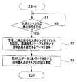
次に、本実施の形態の作用を、図3に示すフローチャートを用いて説明する。
いま、図1及び図2に示す照明システム1の電源を投入し、センタ装置5の制御部5Aを起動させたものとする。
Next, the effect | action of this Embodiment is demonstrated using the flowchart shown in FIG.
Now, it is assumed that the lighting system 1 shown in FIGS. 1 and 2 is turned on and the control unit 5A of the center device 5 is activated.
ここで、室内50の天井面51に配設された各照明器具2a、2b、2c…は、作業者の操作に基づきセンタ装置5の調光制御によって点灯しているものとする。
Here, it is assumed that the
制御部5Aは、電源が投入されると、図示しないメモリから図3に示すプログラムを読み出して実行する。 When the power is turned on, the control unit 5A reads and executes the program shown in FIG. 3 from a memory (not shown).
すると、制御部5Aは、ステップS1の判断処理によって、人感センサ4からの検出信号を受信したか否かの判断を行い、受信したと判断した場合には処理をステップS2に移行し、受信してないと判断した場合には再びステップS1の判断処理を行う。 Then, the control unit 5A determines whether or not the detection signal from the human sensor 4 has been received by the determination process in step S1, and when determining that the detection signal has been received, the control unit 5A shifts the process to step S2 and receives it. If it is determined that it is not, the determination process in step S1 is performed again.
ステップS2の処理では、制御部5Aは、受信した検出信号を判別(例えばHIGHレベルの信号であれば人有りと判別し、LOWレベルの信号であれば人無しと判別する)し、且つ受信した検出信号の人感センサ4のアドレスを認識すると同時に、認識したアドレスとメモリ5Bに格納しているテーブルとを用いて、対応するアドレスの照明器具2と、この照明器具2を調光制御するための照度(照度データ)とを取得する。
In the process of step S2, the control unit 5A determines the received detection signal (for example, determines that there is a person if it is a HIGH level signal and determines that there is no person if it is a LOW level signal), and receives it. At the same time as recognizing the address of the human sensor 4 in the detection signal, using the recognized address and the table stored in the memory 5B, to control the lighting of the
そして、制御部5Aは、認識した対応の照明器具2を、取得したデータ、即ち、照度となるように調光制御を行うとともに、認識したタスク灯3を点灯、又は消灯するように調光制御する。
具体的には、前記したように、制御部5Aは、1つの人感センサ4からの検出結果が人有りであるものとすると、通常、全灯状態である例えば700ルクスの明るさで点灯している全ての照明器具2、或いは対応するグループの照明器具2の明るさを、例えば350ルクスに下げるように省エネ効果のある調光制御を行うと同時に、対応するタスク灯3を点灯するように制御する。
Then, the control unit 5A performs dimming control on the recognized corresponding
Specifically, as described above, if the detection result from one human sensor 4 indicates that there is a person, the control unit 5A normally lights up with a brightness of, for example, 700 lux, which is a full lighting state. The dimming control with energy saving effect is performed so that the brightness of all the
一方、制御部5Aは、1つの人感センサ4からの検出結果が人有りの状態から人無しに変わったものであるとすると、例えば350ルクスの明るさで点灯している全ての照明器具2、或いは対応するグループの照明器具2を、上述したように消灯するように調光制御を行うと同時に、対応するタスク灯3についても消灯するように制御する。
On the other hand, assuming that the detection result from one human sensor 4 has changed from the presence of a person to the absence of a person, the control unit 5A, for example, all the
尚、照明器具2の調光制御については、天井面51全体の照明器具2a、2b、2c…を制御しても良いし、タスク灯3の設置位置に対応するグループ毎の照明器具2a、2b等を制御しても良い。
In addition, about the light control of the
また、照明器具2の調光制御については、メモリ5Bに格納されたテープルにより取得する照度データに基づき行われるが、照明器具2の近傍又はタスク灯3近傍に照度センサを設け、この照度センサにより得られる照度検出結果を用いて的確な照明器具2の明るさを確保するように調光制御を行っても良い。
The light control of the
従って、第1の実施の形態によれば、簡単な構成で、しかも、新たな構成を加えることもなく、室内全体の照明電力の省エネルギー化を図ることができる照明システム1を実現できる。 Therefore, according to the first embodiment, it is possible to realize the lighting system 1 that can save energy of the lighting power of the entire room with a simple configuration and without adding a new configuration.
尚、本実施の形態では、タスク灯3と人感センサとの対応は1:1である関係を満足する構成について説明したが、これに限定されるものではなく、例えば、複数のタスク灯3と、これらの複数のタスク灯3の近傍に設置された1つの人感センサ4とで構成しても良い。 In the present embodiment, the configuration satisfying the relationship in which the correspondence between the task lamp 3 and the human sensor is 1: 1 is not limited to this. For example, a plurality of task lamps 3 are provided. And a single human sensor 4 installed in the vicinity of the plurality of task lights 3.
また、タスク灯3は、複数の照明器具2a、2b、2c…に対して少なくとも1つ設置すれば、本実施の形態で説明したように同様の作用・効果が得られるが、タスク灯3の数については特に限定されるものではない。
In addition, if at least one task lamp 3 is installed for a plurality of
(第2の実施の形態)
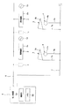
図4は本発明の照明システムの第2の実施の形態に係り、グループ化した人感センサとそれに対応して調光制御する照明器具との関係を示す説明図である。
尚、図4は第1の実施の形態の装置と同様の構成要素については同一の符号を付して説明を省略し、異なる部分のみを説明する。
(Second Embodiment)
FIG. 4 relates to the second embodiment of the lighting system of the present invention, and is an explanatory diagram showing the relationship between the grouped human sensors and the lighting fixtures that perform dimming control corresponding thereto.
In FIG. 4, the same components as those in the apparatus according to the first embodiment are denoted by the same reference numerals, description thereof is omitted, and only different portions are described.
本実施の形態の照明システム1は、複数の人感センサ4a、4b…を予めグルーブ化し、このグループの人感センサの内、検出結果(検出信号)を出力した人感センサ数を認識すると同時に、この認識した人感センサ数に応じて、対応する領域に対応する照明器具2の明るさを変更するように調光制御する。
具体的には、センタ装置5のメモリ5Bには、さらに、予め設定されたグループ毎の人感センサ4a、4b、4c…のアドレス、及びこのグループ内の、検出信号を出力した人感センサ数と、このグループの人感センサの設置位置に対応する照明器具のアドレス、及びこのグループ毎の人感センサ数に応じた照明器具の照度との関係を示すテーブルが格納されている。
The lighting system 1 according to the present embodiment groups a plurality of
Specifically, the memory 5B of the center device 5 further includes preset addresses of the
具体的には、図4に示すように、2つの人感センサ4a、4bをひとつのグループとして設定したとする。
この場合、制御部5Aは、例えば人感センサ4aのみ人有りといった検出信号を出力した場合、前記テーブルを用いて、このひとつの人感センサ数に対応する領域20の照明器具2a〜2fの照度を、例えば350ルクスとなるように調光制御する。同時に、制御部5Aは、人感センサ4aに対応するタスク灯3aを点灯するように制御する。
Specifically, as shown in FIG. 4, it is assumed that two
In this case, when the control unit 5A outputs a detection signal indicating that only the
また、制御部5Aは、例えば人感センサ4a、4bともに人有りといった検出信号を出力した場合、前記テーブルを用いて、これら2つの人感センサ数に対応する領域20の照明器具2a〜2fの照度を、例えば350ルクスより多少明るくなるように調光制御する。同時に、制御部5Aは、人感センサ4a、4bに対応するタスク灯3a、3bを点灯するように制御する。
For example, when the detection unit 5A outputs a detection signal indicating that there is a person in both of the
尚、人感センサ数が1つである場合は、人感センサ数が2つのである場合の照明器具2の照度よりも暗くするように制御することが望ましいが、例えば350ルクスとする制御例は一例であって、机8で作業する作業者が作業しやすい明るさに調光制御すれば良い。
勿論、制御部51は、人感センサ数に応じて、照明器具2の光量を可変する制御が可能である。
In addition, when the number of human sensors is one, it is desirable to control so that it is darker than the illumination intensity of the
Of course, the
また、制御部5Aは、例えば人感センサ4a、4bともに人無しといった検出信号を出力した場合、前記テーブルを用いて、これら2つの人感センサ数に対応する領域20の照明器具2a〜2fを、上述の如く消灯するように制御すると同時に、人感センサ4a、4bに対応するタスク灯3a、3bを消灯するように制御する。
Further, when the control unit 5A outputs, for example, a detection signal indicating that there is no person in both the
尚、明るさを変更制御する照明器具2は、例えば人感センサ4のグループに対応した領域20の照明器具2a〜2fについて説明したが、勿論、天井面51全体に配設された全ての照明器具2a、2b、2c…に対して調光制御を行っても良い。
Note that the
その他の構成、及び作用については、前記第1の実施の形態と同様である。 Other configurations and operations are the same as those in the first embodiment.
従って、第2の実施の形態によれば、グループ内の人感センサ数に応じて、対応する照明器具2の照度を変更するように制御するので、第1の実施の形態によりも室内50全体の照明電力の省エネ効果を向上できるといった効果を得る。
Therefore, according to the second embodiment, control is performed so as to change the illuminance of the
以上の実施の形態に記載した発明は、その実施の形態に限ることなく、その他、実施段階ではその要旨を逸脱しない範囲で種々の変形を実施し得ることが可能である。さらに、前記実施の形態には、種々の段階の発明が含まれており、開示される複数の構成要件における適宜な組合せにより種々の発明が抽出され得る。 The invention described in the above embodiment is not limited to the embodiment, and various modifications can be made without departing from the spirit of the invention in the implementation stage. Further, the embodiments include inventions at various stages, and various inventions can be extracted by appropriately combining a plurality of disclosed constituent elements.
例えば、実施の形態に示される全構成要件から幾つかの構成要件が削除されても、発明が解決しようとする課題の欄で述べた課題が解決でき、発明の効果で述べられている効果が得られる場合には、この構成要件が削除された構成が発明として抽出され得る。 For example, even if some constituent elements are deleted from all the constituent elements shown in the embodiment, the problems described in the column of problems to be solved by the invention can be solved, and the effects described in the effects of the invention can be achieved. In the case of being obtained, a configuration from which this configuration requirement is deleted can be extracted as an invention.
1…照明システム、
2…照明器具、
3…タスク灯、
3B…照明部、
4…人感センサ、
5…センタ装置、
5B…メモリ、
5A…制御部、
6、7…伝送線、
7a、7b…接続線、
8…机、
20… 領域、
50…室内、
51…天井面、
52…床。
1 ... Lighting system,
2 ... Lighting equipment,
3 ... Task light,
3B ... Illumination part,
4 ... Human sensor,
5 ... Center device,
5B ... Memory,
5A ... control unit,
6, 7 ... transmission line,
7a, 7b ... connecting line,
8 ... desk,
20 ... area,
50 ... indoors,
51 ... Ceiling surface
52 ... Floor.
Claims (4)
机の上面の所定の照射範囲に照明光を照射するためのタスク灯と;
前記照射範囲に対応する範囲内の人の有無を検出する人感センサと;
前記照明器具及び前記タスク灯に、夫々の調光を制御するための制御信号の伝送が可能であり、前記人感センサの検出結果に基づいて、前記照明器具及び前記タスク灯の調光を制御する制御部と;
を具備したことを特徴とする照明システム。 Lighting fixtures arranged on the ceiling surface;
A task lamp for irradiating illumination light to a predetermined irradiation range on the upper surface of the desk;
A human sensor for detecting the presence or absence of a person within a range corresponding to the irradiation range;
It is possible to transmit a control signal for controlling the dimming to the lighting fixture and the task lamp, and control the dimming of the lighting fixture and the task lamp based on the detection result of the human sensor. A control unit to perform;
An illumination system comprising:
前記タスク灯及び前記人感センサは、夫々対応させて複数設けられ、
前記制御部は、予め設定されたグループの人感センサの内、人を検出した人感センサ数に応じて、この人を検出した人感センサに対応した前記タスク灯を照明する領域に対応する前記照明器具の明るさを変更するように調光制御することを特徴とする請求項1から請求項3の何れか1項に記載の照明システム。 A plurality of the lighting fixtures are disposed,
A plurality of task lights and human sensors are provided in correspondence with each other,
The control unit corresponds to a region that illuminates the task lamp corresponding to the human sensor that has detected the person, according to the number of human sensors that have detected the person among the human sensors of the preset group. The lighting system according to any one of claims 1 to 3, wherein dimming control is performed so as to change a brightness of the lighting fixture.
Priority Applications (1)
| Application Number | Priority Date | Filing Date | Title |
|---|---|---|---|
| JP2008324633A JP2010146923A (en) | 2008-12-19 | 2008-12-19 | Lighting system |
Applications Claiming Priority (1)
| Application Number | Priority Date | Filing Date | Title |
|---|---|---|---|
| JP2008324633A JP2010146923A (en) | 2008-12-19 | 2008-12-19 | Lighting system |
Publications (1)
| Publication Number | Publication Date |
|---|---|
| JP2010146923A true JP2010146923A (en) | 2010-07-01 |
Family
ID=42567099
Family Applications (1)
| Application Number | Title | Priority Date | Filing Date |
|---|---|---|---|
| JP2008324633A Pending JP2010146923A (en) | 2008-12-19 | 2008-12-19 | Lighting system |
Country Status (1)
| Country | Link |
|---|---|
| JP (1) | JP2010146923A (en) |
Cited By (6)
| Publication number | Priority date | Publication date | Assignee | Title |
|---|---|---|---|---|
| JP2012209803A (en) * | 2011-03-30 | 2012-10-25 | Hitachi Appliances Inc | Interlocking control device |
| JP2014089918A (en) * | 2012-10-31 | 2014-05-15 | Panasonic Corp | Illumination control system |
| JP2016541089A (en) * | 2013-10-23 | 2016-12-28 | パワーキャスト コーポレイションPowercast Corporation | Automation system for lighting control |
| US10149370B2 (en) | 2015-05-04 | 2018-12-04 | Powercast Corporation | Automated system for lighting control |
| US10638399B2 (en) | 2012-03-21 | 2020-04-28 | Powercast Corporation | Wireless sensor system, method and apparatus with switch and outlet control |
| US10979961B2 (en) | 2016-10-07 | 2021-04-13 | Powercast Corporation | Automated system for lighting control |
-
2008
- 2008-12-19 JP JP2008324633A patent/JP2010146923A/en active Pending
Cited By (14)
| Publication number | Priority date | Publication date | Assignee | Title |
|---|---|---|---|---|
| JP2012209803A (en) * | 2011-03-30 | 2012-10-25 | Hitachi Appliances Inc | Interlocking control device |
| US10638399B2 (en) | 2012-03-21 | 2020-04-28 | Powercast Corporation | Wireless sensor system, method and apparatus with switch and outlet control |
| US12369095B2 (en) | 2012-03-21 | 2025-07-22 | Powercast Corporation | Wireless sensor system, method and apparatus with switch and outlet control |
| US11917519B2 (en) | 2012-03-21 | 2024-02-27 | Powercast Corporation | Wireless sensor system, method and apparatus with switch and outlet control |
| US11457395B2 (en) | 2012-03-21 | 2022-09-27 | Powercast Corporation | Wireless sensor system, method and apparatus with switch and outlet control |
| JP2014089918A (en) * | 2012-10-31 | 2014-05-15 | Panasonic Corp | Illumination control system |
| US11102869B2 (en) | 2013-10-23 | 2021-08-24 | Powercast Corporation | Automated system for lighting control |
| US10455663B2 (en) | 2013-10-23 | 2019-10-22 | Powercast Corporation | Automated system for lighting control |
| JP2016541089A (en) * | 2013-10-23 | 2016-12-28 | パワーキャスト コーポレイションPowercast Corporation | Automation system for lighting control |
| US11039524B2 (en) | 2015-05-04 | 2021-06-15 | Powercast Corporation | Automated system for lighting control |
| US10524337B2 (en) | 2015-05-04 | 2019-12-31 | Powercast Corporation | Automated system for lighting control |
| US10149370B2 (en) | 2015-05-04 | 2018-12-04 | Powercast Corporation | Automated system for lighting control |
| US10979961B2 (en) | 2016-10-07 | 2021-04-13 | Powercast Corporation | Automated system for lighting control |
| US11696211B2 (en) | 2016-10-07 | 2023-07-04 | Powercast Corporation | Automated system for lighting control |
Similar Documents
| Publication | Publication Date | Title |
|---|---|---|
| CN102162609B (en) | Lighting device and lighting system | |
| CN104285503B (en) | Apparatus and method for dynamic lighting control | |
| EP2696662A2 (en) | Lighting control system and lighting control method | |
| JP2012533844A (en) | Lighting fixture with touch pattern control interface | |
| JP2010146923A (en) | Lighting system | |
| JP2010080102A (en) | Lighting control system | |
| US20130241420A1 (en) | Dynamic lighting control | |
| KR101213936B1 (en) | Lighting Control System | |
| KR20180024597A (en) | Smart energy-saiving stand using automatic lighting control | |
| WO2010067654A1 (en) | Illuminating apparatus and illuminating system | |
| JP2015060826A (en) | Lighting control system | |
| JP2010153243A (en) | Lighting device and lighting method | |
| JP5907344B2 (en) | Lighting control system and lighting control method | |
| JP4406826B2 (en) | Lighting control system | |
| JP2010186635A (en) | Illumination apparatus, illumination system, and illumination method | |
| JP2009231071A (en) | Lighting control system | |
| JP2014130833A (en) | Dimming control system | |
| JP4915662B2 (en) | Lighting system | |
| JP2012064529A (en) | Lighting control system | |
| JP6600950B2 (en) | Lighting system | |
| JP2008235114A (en) | Lighting control method and lighting control system | |
| JP2011175782A (en) | Lighting fixture | |
| JP2006085934A (en) | Lighting control system | |
| KR20130091018A (en) | Led illuminating apparatus for a parking lot and method for illuminating a parking lot using a led illuminating lamp | |
| JP2020161276A (en) | Lighting control system for toilet space |