JP2010146818A - Lighting fixture for vehicle - Google Patents
Lighting fixture for vehicle Download PDFInfo
- Publication number
- JP2010146818A JP2010146818A JP2008321599A JP2008321599A JP2010146818A JP 2010146818 A JP2010146818 A JP 2010146818A JP 2008321599 A JP2008321599 A JP 2008321599A JP 2008321599 A JP2008321599 A JP 2008321599A JP 2010146818 A JP2010146818 A JP 2010146818A
- Authority
- JP
- Japan
- Prior art keywords
- light
- light guide
- lamp
- extending direction
- incident
- Prior art date
- Legal status (The legal status is an assumption and is not a legal conclusion. Google has not performed a legal analysis and makes no representation as to the accuracy of the status listed.)
- Granted
Links
Images

Classifications
-
- F—MECHANICAL ENGINEERING; LIGHTING; HEATING; WEAPONS; BLASTING
- F21—LIGHTING
- F21S—NON-PORTABLE LIGHTING DEVICES; SYSTEMS THEREOF; VEHICLE LIGHTING DEVICES SPECIALLY ADAPTED FOR VEHICLE EXTERIORS
- F21S43/00—Signalling devices specially adapted for vehicle exteriors, e.g. brake lamps, direction indicator lights or reversing lights
- F21S43/20—Signalling devices specially adapted for vehicle exteriors, e.g. brake lamps, direction indicator lights or reversing lights characterised by refractors, transparent cover plates, light guides or filters
- F21S43/235—Light guides
-
- F—MECHANICAL ENGINEERING; LIGHTING; HEATING; WEAPONS; BLASTING
- F21—LIGHTING
- F21V—FUNCTIONAL FEATURES OR DETAILS OF LIGHTING DEVICES OR SYSTEMS THEREOF; STRUCTURAL COMBINATIONS OF LIGHTING DEVICES WITH OTHER ARTICLES, NOT OTHERWISE PROVIDED FOR
- F21V7/00—Reflectors for light sources
- F21V7/005—Reflectors for light sources with an elongated shape to cooperate with linear light sources
-
- F—MECHANICAL ENGINEERING; LIGHTING; HEATING; WEAPONS; BLASTING
- F21—LIGHTING
- F21S—NON-PORTABLE LIGHTING DEVICES; SYSTEMS THEREOF; VEHICLE LIGHTING DEVICES SPECIALLY ADAPTED FOR VEHICLE EXTERIORS
- F21S43/00—Signalling devices specially adapted for vehicle exteriors, e.g. brake lamps, direction indicator lights or reversing lights
- F21S43/20—Signalling devices specially adapted for vehicle exteriors, e.g. brake lamps, direction indicator lights or reversing lights characterised by refractors, transparent cover plates, light guides or filters
- F21S43/235—Light guides
- F21S43/236—Light guides characterised by the shape of the light guide
- F21S43/237—Light guides characterised by the shape of the light guide rod-shaped
-
- F—MECHANICAL ENGINEERING; LIGHTING; HEATING; WEAPONS; BLASTING
- F21—LIGHTING
- F21S—NON-PORTABLE LIGHTING DEVICES; SYSTEMS THEREOF; VEHICLE LIGHTING DEVICES SPECIALLY ADAPTED FOR VEHICLE EXTERIORS
- F21S43/00—Signalling devices specially adapted for vehicle exteriors, e.g. brake lamps, direction indicator lights or reversing lights
- F21S43/20—Signalling devices specially adapted for vehicle exteriors, e.g. brake lamps, direction indicator lights or reversing lights characterised by refractors, transparent cover plates, light guides or filters
- F21S43/235—Light guides
- F21S43/242—Light guides characterised by the emission area
- F21S43/245—Light guides characterised by the emission area emitting light from one or more of its major surfaces
-
- F—MECHANICAL ENGINEERING; LIGHTING; HEATING; WEAPONS; BLASTING
- F21—LIGHTING
- F21S—NON-PORTABLE LIGHTING DEVICES; SYSTEMS THEREOF; VEHICLE LIGHTING DEVICES SPECIALLY ADAPTED FOR VEHICLE EXTERIORS
- F21S43/00—Signalling devices specially adapted for vehicle exteriors, e.g. brake lamps, direction indicator lights or reversing lights
- F21S43/20—Signalling devices specially adapted for vehicle exteriors, e.g. brake lamps, direction indicator lights or reversing lights characterised by refractors, transparent cover plates, light guides or filters
- F21S43/235—Light guides
- F21S43/247—Light guides with a single light source being coupled into the light guide
-
- F—MECHANICAL ENGINEERING; LIGHTING; HEATING; WEAPONS; BLASTING
- F21—LIGHTING
- F21S—NON-PORTABLE LIGHTING DEVICES; SYSTEMS THEREOF; VEHICLE LIGHTING DEVICES SPECIALLY ADAPTED FOR VEHICLE EXTERIORS
- F21S43/00—Signalling devices specially adapted for vehicle exteriors, e.g. brake lamps, direction indicator lights or reversing lights
- F21S43/30—Signalling devices specially adapted for vehicle exteriors, e.g. brake lamps, direction indicator lights or reversing lights characterised by reflectors
-
- F—MECHANICAL ENGINEERING; LIGHTING; HEATING; WEAPONS; BLASTING
- F21—LIGHTING
- F21S—NON-PORTABLE LIGHTING DEVICES; SYSTEMS THEREOF; VEHICLE LIGHTING DEVICES SPECIALLY ADAPTED FOR VEHICLE EXTERIORS
- F21S43/00—Signalling devices specially adapted for vehicle exteriors, e.g. brake lamps, direction indicator lights or reversing lights
- F21S43/30—Signalling devices specially adapted for vehicle exteriors, e.g. brake lamps, direction indicator lights or reversing lights characterised by reflectors
- F21S43/31—Optical layout thereof
-
- G—PHYSICS
- G02—OPTICS
- G02B—OPTICAL ELEMENTS, SYSTEMS OR APPARATUS
- G02B6/00—Light guides; Structural details of arrangements comprising light guides and other optical elements, e.g. couplings
- G02B6/0001—Light guides; Structural details of arrangements comprising light guides and other optical elements, e.g. couplings specially adapted for lighting devices or systems
- G02B6/0011—Light guides; Structural details of arrangements comprising light guides and other optical elements, e.g. couplings specially adapted for lighting devices or systems the light guides being planar or of plate-like form
- G02B6/0033—Means for improving the coupling-out of light from the light guide
- G02B6/0035—Means for improving the coupling-out of light from the light guide provided on the surface of the light guide or in the bulk of it
- G02B6/0038—Linear indentations or grooves, e.g. arc-shaped grooves or meandering grooves, extending over the full length or width of the light guide
-
- G—PHYSICS
- G02—OPTICS
- G02B—OPTICAL ELEMENTS, SYSTEMS OR APPARATUS
- G02B6/00—Light guides; Structural details of arrangements comprising light guides and other optical elements, e.g. couplings
- G02B6/0001—Light guides; Structural details of arrangements comprising light guides and other optical elements, e.g. couplings specially adapted for lighting devices or systems
- G02B6/0011—Light guides; Structural details of arrangements comprising light guides and other optical elements, e.g. couplings specially adapted for lighting devices or systems the light guides being planar or of plate-like form
- G02B6/0033—Means for improving the coupling-out of light from the light guide
- G02B6/0035—Means for improving the coupling-out of light from the light guide provided on the surface of the light guide or in the bulk of it
- G02B6/0045—Means for improving the coupling-out of light from the light guide provided on the surface of the light guide or in the bulk of it by shaping at least a portion of the light guide
-
- G—PHYSICS
- G02—OPTICS
- G02B—OPTICAL ELEMENTS, SYSTEMS OR APPARATUS
- G02B6/00—Light guides; Structural details of arrangements comprising light guides and other optical elements, e.g. couplings
- G02B6/0001—Light guides; Structural details of arrangements comprising light guides and other optical elements, e.g. couplings specially adapted for lighting devices or systems
- G02B6/0011—Light guides; Structural details of arrangements comprising light guides and other optical elements, e.g. couplings specially adapted for lighting devices or systems the light guides being planar or of plate-like form
- G02B6/0033—Means for improving the coupling-out of light from the light guide
- G02B6/005—Means for improving the coupling-out of light from the light guide provided by one optical element, or plurality thereof, placed on the light output side of the light guide
- G02B6/0055—Reflecting element, sheet or layer
-
- F—MECHANICAL ENGINEERING; LIGHTING; HEATING; WEAPONS; BLASTING
- F21—LIGHTING
- F21S—NON-PORTABLE LIGHTING DEVICES; SYSTEMS THEREOF; VEHICLE LIGHTING DEVICES SPECIALLY ADAPTED FOR VEHICLE EXTERIORS
- F21S43/00—Signalling devices specially adapted for vehicle exteriors, e.g. brake lamps, direction indicator lights or reversing lights
- F21S43/10—Signalling devices specially adapted for vehicle exteriors, e.g. brake lamps, direction indicator lights or reversing lights characterised by the light source
- F21S43/13—Signalling devices specially adapted for vehicle exteriors, e.g. brake lamps, direction indicator lights or reversing lights characterised by the light source characterised by the type of light source
- F21S43/14—Light emitting diodes [LED]
-
- F—MECHANICAL ENGINEERING; LIGHTING; HEATING; WEAPONS; BLASTING
- F21—LIGHTING
- F21W—INDEXING SCHEME ASSOCIATED WITH SUBCLASSES F21K, F21L, F21S and F21V, RELATING TO USES OR APPLICATIONS OF LIGHTING DEVICES OR SYSTEMS
- F21W2103/00—Exterior vehicle lighting devices for signalling purposes
-
- F—MECHANICAL ENGINEERING; LIGHTING; HEATING; WEAPONS; BLASTING
- F21—LIGHTING
- F21W—INDEXING SCHEME ASSOCIATED WITH SUBCLASSES F21K, F21L, F21S and F21V, RELATING TO USES OR APPLICATIONS OF LIGHTING DEVICES OR SYSTEMS
- F21W2107/00—Use or application of lighting devices on or in particular types of vehicles
- F21W2107/10—Use or application of lighting devices on or in particular types of vehicles for land vehicles
-
- F—MECHANICAL ENGINEERING; LIGHTING; HEATING; WEAPONS; BLASTING
- F21—LIGHTING
- F21Y—INDEXING SCHEME ASSOCIATED WITH SUBCLASSES F21K, F21L, F21S and F21V, RELATING TO THE FORM OR THE KIND OF THE LIGHT SOURCES OR OF THE COLOUR OF THE LIGHT EMITTED
- F21Y2115/00—Light-generating elements of semiconductor light sources
- F21Y2115/10—Light-emitting diodes [LED]
-
- G—PHYSICS
- G02—OPTICS
- G02B—OPTICAL ELEMENTS, SYSTEMS OR APPARATUS
- G02B6/00—Light guides; Structural details of arrangements comprising light guides and other optical elements, e.g. couplings
- G02B6/0001—Light guides; Structural details of arrangements comprising light guides and other optical elements, e.g. couplings specially adapted for lighting devices or systems
- G02B6/0011—Light guides; Structural details of arrangements comprising light guides and other optical elements, e.g. couplings specially adapted for lighting devices or systems the light guides being planar or of plate-like form
- G02B6/0033—Means for improving the coupling-out of light from the light guide
- G02B6/0035—Means for improving the coupling-out of light from the light guide provided on the surface of the light guide or in the bulk of it
- G02B6/0045—Means for improving the coupling-out of light from the light guide provided on the surface of the light guide or in the bulk of it by shaping at least a portion of the light guide
- G02B6/0046—Tapered light guide, e.g. wedge-shaped light guide
Landscapes
- Engineering & Computer Science (AREA)
- General Engineering & Computer Science (AREA)
- Physics & Mathematics (AREA)
- Optics & Photonics (AREA)
- General Physics & Mathematics (AREA)
- Microelectronics & Electronic Packaging (AREA)
- Non-Portable Lighting Devices Or Systems Thereof (AREA)
Abstract
【課題】導光体を用いた車両用灯具において、好適に発光面積を大きくする。
【解決手段】車両用灯具は、入射面22aから入射した光を内部で導光しながら延出方向に沿った側面から外部に出射する導光体22と、入射面22aに光が入射するよう配置されたLED32と、導光体22の延出方向に沿って配置され、側面から出射された光の一部を灯具前方へ反射するリフレクタ24とを備える。導光体22は、延出方向に直交する断面の面積が、入射面22aからの距離に応じて減少するように形成されている。
【選択図】図2In a vehicular lamp using a light guide, a light emitting area is preferably increased.
The vehicular lamp includes a light guide 22 that emits light incident from an incident surface 22a to the outside and guides the light to the incident surface 22a. The LED 32 is disposed, and the reflector 24 is disposed along the extending direction of the light guide 22 and reflects part of the light emitted from the side surface to the front of the lamp. The light guide 22 is formed so that the area of the cross section perpendicular to the extending direction decreases according to the distance from the incident surface 22a.
[Selection] Figure 2
Description
本発明は、車両用灯具に関し、特に導光体を用いた車両用灯具に関する。 The present invention relates to a vehicular lamp, and more particularly to a vehicular lamp using a light guide.
従来、テールランプやストップランプに用いられる車両用灯具として、棒状の導光体の端部にLEDを配置し、線状の発光が得られるように構成されたものが知られている(たとえば特許文献1参照)。
ところで、テールランプやストップランプにおいては、法規により所定値以上の発光面積を確保する必要がある。また、点灯時の見栄えの観点からも発光面積を大きくすることが求められる場合がある。上述のような導光体を用いた車両用灯具では、灯具全体としての発光面積を大きくしようとした場合、導光体を大型化することが考えられるが、この場合、光が分散されてしまうため輝度が低下してしまう。輝度の低下を補うために、LEDの数を増やしたり、LEDを高出力にすることも考えられるが、この場合、コストや消費電力が増大してしまう。 By the way, in a tail lamp and a stop lamp, it is necessary to ensure a light emission area of a predetermined value or more according to a law. In addition, it may be required to increase the light emitting area from the viewpoint of appearance when lighting. In the vehicular lamp using the light guide as described above, it is conceivable to increase the size of the light guide when attempting to increase the light emission area of the entire lamp, but in this case, the light is dispersed. Therefore, the brightness is lowered. In order to compensate for the decrease in luminance, it is conceivable to increase the number of LEDs or increase the output of the LEDs. However, in this case, cost and power consumption increase.
本発明はこうした状況に鑑みてなされたものであり、その目的は、導光体を用いた車両用灯具において、好適に発光面積を大きくすることのできる車両用灯具を提供することにある。 This invention is made | formed in view of such a condition, The objective is to provide the vehicle lamp which can enlarge a light emission area suitably in the vehicle lamp using a light guide.
上記課題を解決するために、本発明のある態様の車両用灯具は、端面から入射した光を内部で導光しながら延出方向に沿った側面から外部に出射する導光体と、端面に光が入射するよう配置された光源と、導光体の延出方向に沿って配置され、側面から出射された光の一部を灯具前方へ反射するリフレクタとを備える。 In order to solve the above-described problems, a vehicle lamp according to an aspect of the present invention includes a light guide that emits light incident from an end surface to the outside from a side surface along the extending direction while guiding light incident on the end surface, and an end surface. A light source arranged so that light enters and a reflector arranged along the extending direction of the light guide and reflecting a part of the light emitted from the side surface forward of the lamp.
この態様によると、導光体の側面から直接出射される光と、導光体の側面から出射された後リフレクタにより反射される光とが車両用灯具から出射されるので、リフレクタの反射面分だけ灯具全体としての発光面積を大きくすることができる。この態様では、導光体を大型化したり、LEDの数を増やしたり、LEDを高出力化したりする必要がないので、コストや消費電力の増大を抑制しつつ、好適に発光面積を大きくすることができる。 According to this aspect, the light that is directly emitted from the side surface of the light guide and the light that is emitted from the side surface of the light guide and then reflected by the reflector are emitted from the vehicle lamp. Only the light emitting area of the entire lamp can be increased. In this aspect, since it is not necessary to increase the size of the light guide, increase the number of LEDs, or increase the output of the LEDs, it is desirable to appropriately increase the light emitting area while suppressing an increase in cost and power consumption. Can do.
導光体は、延出方向に直交する断面の面積が、光が入射する端面からの距離に応じて減少するように形成されていてもよい。この場合、光が入射する端面から離れるにつれて導光体内を伝搬する光量は少なくなるが、断面積を減少させることにより光が集められるので、導光体の延出方向にわたって導光体を略均一に光らせることが可能となる。略均一に光らせるために最適な断面積の減少のさせ方は、導光体の形状や材質によって異なるが、実験やシミュレーションにより適宜設計すればよい。 The light guide may be formed such that an area of a cross section perpendicular to the extending direction decreases according to a distance from an end surface on which light enters. In this case, the amount of light propagating through the light guide decreases as it moves away from the incident end face, but the light is collected by reducing the cross-sectional area, so that the light guide is substantially uniform over the extending direction of the light guide. It becomes possible to make it shine. The optimum method for reducing the cross-sectional area for making the light shine substantially uniformly varies depending on the shape and material of the light guide, but may be appropriately designed by experiment or simulation.
導光体は、延出方向に直交する断面の面積が、光が入射する端面からの距離に応じて増加するように形成されていてもよい。このように断面積を増加させることにより、発光輝度が漸次減少するグラデーション発光が可能となり、意匠的に斬新性のある車両用灯具を実現できる。断面積の増加のさせ方は、所望の配光パターンに応じて実験やシミュレーションにより適宜設計すればよい。 The light guide may be formed such that an area of a cross section perpendicular to the extending direction increases in accordance with a distance from an end surface on which light enters. By increasing the cross-sectional area in this way, gradation light emission in which the light emission luminance gradually decreases can be realized, and a vehicle lamp having a novel design can be realized. The method of increasing the cross-sectional area may be appropriately designed by experiment or simulation according to the desired light distribution pattern.
リフレクタは、導光体の延出方向に沿って反射面の大きさが略一定となるように形成されていてもよい。この場合、上述のように導光体の断面積を光が入射する端面からの距離に応じて変化させたとしても、灯具全体としての発光面積を略一定に保つことができ、灯具として必要とされる所定の発光面積を確保することができる。 The reflector may be formed such that the size of the reflecting surface is substantially constant along the extending direction of the light guide. In this case, even if the cross-sectional area of the light guide is changed according to the distance from the end surface where the light is incident as described above, the light emitting area of the entire lamp can be kept substantially constant, which is necessary as a lamp. A predetermined light emitting area can be secured.
リフレクタは、導光体の延出方向に沿って反射面の大きさが変化するように形成されていてもよい。この場合、灯具全体としての発光面積を延出方向に沿って変化させることができるので、意匠的に斬新性のある車両用灯具を実現できる。 The reflector may be formed so that the size of the reflecting surface changes along the extending direction of the light guide. In this case, since the light emission area of the entire lamp can be changed along the extending direction, a vehicular lamp having a novel design can be realized.
本発明によれば、導光体を用いた車両用灯具において、好適に発光面積を大きくすることができる。 According to the present invention, in the vehicular lamp using the light guide, the light emission area can be suitably increased.
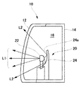
以下、図面を参照して本発明の実施の形態について詳細に説明する。図1は、本発明の実施の形態に係る車両用灯具10の断面図である。本実施の形態に係る車両用灯具10は、車両後部に設けられるテールランプまたはストップランプとして用いられる。
Hereinafter, embodiments of the present invention will be described in detail with reference to the drawings. FIG. 1 is a cross-sectional view of a
車両用灯具10は、ランプボディ14と、ランプボディ14の前面開口部を覆う透明なカバー12とを備える。ランプボディ14とカバー12は、灯室16を形成しており、該灯室16内には導光体22とリフレクタ24とを含んで構成される灯具ユニット20が設けられている。
The
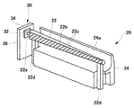
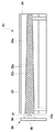
図2は、灯具ユニット20の斜視図である。また、図3は、灯具ユニット20の正面図である。図2および図3に示すように、灯具ユニット20は、導光体22と、リフレクタ24と、発光ユニット30とを備える。
FIG. 2 is a perspective view of the
導光体22は、アクリルなどの透明樹脂を押出成形することにより形成された棒状の導光体である。導光体22の延出方向(長手方向)に直交する断面形状は略円形状である。導光体22は、一方の端面が発光ユニット30から光を入射する入射面22aとされている。また、導光体22の側面のうち前面22bは平面状に形成されており、該前面22bには光を拡散させるためのステップ22cが形成されている。本実施の形態では、斜線状のステップ22cが形成されている。また本実施の形態では、導光体22は、延出方向に直交する断面の面積が、入射面22aからの距離に応じて減少するように形成されている。導光体22は、両端部に設けられた支持部22dによりランプボディ14上に支持されている。このように形成された導光体22は、入射面22aから入射した光を内部で導光しながら延出方向に沿った側面から外部に出射する。
The
発光ユニット30は、導光体22に光を供給する光源である。発光ユニット30は、導光体22の入射面22aに向けて光を照射するLED32と、LED32に電流を供給する基板34と、LED32から発生した熱を放熱するヒートシンク36とを備える。
The
リフレクタ24は、棒状のリフレクタであり、導光体22の延出方向に沿って配置され、導光体22の側面から出射された光の一部を灯具前方へ反射する。リフレクタ24の反射面24aは、延出方向(長手方向)に直交する断面において略円弧状に形成されており、導光体22の背面から下面までを覆うように形成されている。本実施の形態において、リフレクタ24は、導光体22の延出方向に沿って反射面24aの大きさが略一定となるように形成されている。導光体22の延出方向に沿って反射面24aの大きさが略一定とは、延出方向に直交する断面における反射面24aの外周が、延出方向にわたって略一定であるということである。
The
以上のように構成された車両用灯具10の動作について説明する。図1には、車両用灯具10から出射される光を矢印で示している。車両用灯具10において、LED32に電流が供給されると、LED32から出射された光は入射面22aより導光体22内に入射する。導光体22内に入射した光は、導光体22内を進行しながら、導光体22の側面より出射される。ここで、導光体22の前面22bより出射された光は、ステップ22cにより拡散された後、カバー12を介して灯具前方に出射される(符号L1で光線を示す)。一方、導光体22の背面から下面までの面から出射された光は、リフレクタ24の反射面24aにより反射された後、カバー12を介して灯具前方に出射される(符号L2で光線を示す)。
The operation of the
このように本実施の形態に係る車両用灯具10では、導光体22の前面22bから直接出射される光L1と、導光体22から出射された後、リフレクタ24の反射面24aで反射される光L2とが灯具前方に出射される。リフレクタ24の反射面24aの面積が灯具全体としての発光面積となるので、導光体22を単独で用いた場合よりも発光面積を大きくすることができる。発光面積を増やすために導光体22を大型化したり、LED32の数を増やしたり、LED32を高出力化したりする必要がないので、コストや消費電力の増大を抑制しつつ、好適に発光面積を大きくすることができる。
As described above, in the
また、本実施の形態に係る車両用灯具10では、導光体22は、延出方向に直交する断面の面積が、入射面22aからの距離に応じて減少するように形成されている。この場合、入射面22aから離れるにつれて導光体22内を伝搬する光量は少なくなるが、断面積を減少させることにより光が集められるので、延出方向にわたって導光体22を略均一に光らせることが可能となる。略均一に光らせるために最適な断面積の減少のさせ方は、導光体22の形状や材質によって異なるが、実験やシミュレーションにより適宜設計することができる。
In the
また、本実施の形態に係る車両用灯具10では、リフレクタ24は、導光体22の延出方向に沿って反射面24aの大きさが略一定となるように形成されている。この場合、導光体22の断面積を入射面22aからの距離に応じて減少させたとしても、灯具全体としての発光面積を略一定に保つことができ、灯具として必要とされる所定の発光面積を確保することができる。
In the
図4(a)〜(d)は、導光体の変形例を示す。図4(a)に示す導光体22は、ステップ22cの形状は上述の実施の形態と同じであるが、前面22bの面積をより大きく形成したものである。この場合、前面22bの面積が大きくなったことにより、輝度の高い発光領域を増やすことができる。
4A to 4D show a modification of the light guide. In the
図4(b)に示す導光体22は、導光体22の延出方向に直交する断面を長方形状としたものである。前面22bに形成したステップ22cの形状は、図4(a)と同様である。この場合、導光体22の形状に合わせてリフレクタの反射面を変形してもよい。
The
図4(c)に示す導光体22は、導光体22の断面は図4(b)と同様に長方形状であるが、前面22bに形成するステップ22cの形状を変形したものである。また、図4(d)に示す導光体22は、導光体22の断面は図2および図3と同様であるが、前面22bに形成するステップ22cの形状を変形したものである。図4(c)および図4(d)では、より細かいステップ22cを形成しているが、このようにステップ22cを様々な形状に変化させることにより、意匠的に斬新な配光パターンを作り出すことができる。
The
以上、実施の形態をもとに本発明を説明した。これらの実施形態は例示であり、各構成要素や各処理プロセスの組合せにいろいろな変形例が可能なこと、またそうした変形例も本発明の範囲にあることは当業者に理解されるところである。 The present invention has been described above based on the embodiment. It should be understood by those skilled in the art that these embodiments are exemplifications, and that various modifications can be made to the combination of each component and each processing process, and such modifications are also within the scope of the present invention.
たとえば、導光体は、延出方向に直交する断面の面積が、入射面からの距離に応じて増加するように形成されていてもよい。このように断面積を増加させることにより発光輝度が漸次減少するグラデーション発光が可能となり、意匠的に斬新性のある車両用灯具を実現できる。たとえば、車両用灯具をテールランプとして車両に設けた場合には、車両中央から左右方向に向かって徐々に発光輝度を減少させていくことにより、単に一様な輝度で発光させた場合よりも斬新な配光パターンを作り出すことができる。断面積の増加のさせ方は、所望の発光パターンに応じて実験やシミュレーションにより適宜設計すればよい。 For example, the light guide may be formed such that the cross-sectional area perpendicular to the extending direction increases in accordance with the distance from the incident surface. By increasing the cross-sectional area in this manner, gradation light emission in which the light emission luminance gradually decreases is possible, and a vehicle lamp having a novel design can be realized. For example, when a vehicular lamp is provided in a vehicle as a tail lamp, the emission luminance is gradually decreased from the center of the vehicle in the left-right direction, so that it is more innovative than simply emitting light with uniform luminance. A light distribution pattern can be created. The method of increasing the cross-sectional area may be appropriately designed by experiment or simulation according to the desired light emission pattern.
また、リフレクタは、導光体の延出方向に沿って反射面の大きさが変化するように形成されていてもよい。導光体の延出方向に沿って反射面の大きさが変化するとは、延出方向に直交する断面における反射面の外周が、延出方向に沿って変化するということである。たとえば、導光体の延出方向に沿って反射面の大きさを増加させたり、減少させたりしてもよい。この場合、灯具全体としての発光面積を延出方向に沿って変化させることができるので、意匠的に斬新性のある車両用灯具を実現できる。たとえば、車両用灯具をテールランプとして車両に設けた場合には、車両中央から左右方向に向かって徐々に発光面積を小さくしていくことにより、車両の端に向かって光が消えていくような斬新な配光パターンを作り出すことができる。 Further, the reflector may be formed so that the size of the reflecting surface changes along the extending direction of the light guide. The change of the size of the reflecting surface along the extending direction of the light guide means that the outer periphery of the reflecting surface in the cross section orthogonal to the extending direction changes along the extending direction. For example, the size of the reflecting surface may be increased or decreased along the extending direction of the light guide. In this case, since the light emission area of the entire lamp can be changed along the extending direction, a vehicular lamp having a novel design can be realized. For example, when a vehicular lamp is provided in a vehicle as a tail lamp, the light emission area gradually decreases from the center of the vehicle in the left-right direction, so that the light disappears toward the end of the vehicle. A simple light distribution pattern.
上述の実施の形態では、光源としてLEDを用いたが、もちろんバルブ等の他の光源を用いることも可能である。 In the above-described embodiment, the LED is used as the light source. However, other light sources such as a bulb may be used.
図2および図3では、直線状の車両用灯具を示したが、車両用灯具の形状は直線状のものに限られず、曲線状であってもよい。たとえば、車両用灯具をテールランプとして車両に設ける場合には、車両の後部ボディの形状に合わせて曲線状に形成されてもよい。 2 and 3 show a linear vehicle lamp, the shape of the vehicle lamp is not limited to a linear shape, and may be a curved shape. For example, when the vehicle lamp is provided in the vehicle as a tail lamp, it may be formed in a curved shape in accordance with the shape of the rear body of the vehicle.
10 車両用灯具、 12 カバー、 14 ランプボディ、 16 灯室、 20 灯具ユニット、 22 導光体、 24 リフレクタ、 30 発光ユニット、 32 LED、 34 基板、 36 ヒートシンク。
DESCRIPTION OF
Claims (5)
前記端面に光が入射するよう配置された光源と、
前記導光体の延出方向に沿って配置され、前記側面から出射された光の一部を灯具前方へ反射するリフレクタと、
を備えることを特徴とする車両用灯具。 A light guide that emits the light incident from the end face to the outside from the side surface along the extending direction while guiding the light inside;
A light source disposed so that light is incident on the end face;
A reflector that is arranged along the extending direction of the light guide and reflects a part of the light emitted from the side surface forward of the lamp;
A vehicular lamp characterized by comprising:
Priority Applications (5)
| Application Number | Priority Date | Filing Date | Title |
|---|---|---|---|
| JP2008321599A JP5275776B2 (en) | 2008-12-17 | 2008-12-17 | Vehicle lighting |
| KR1020090123911A KR20100070295A (en) | 2008-12-17 | 2009-12-14 | Car luminaires |
| US12/639,792 US8226282B2 (en) | 2008-12-17 | 2009-12-16 | Vehicle lamp |
| CN2009102525111A CN101749623B (en) | 2008-12-17 | 2009-12-17 | Vehicle lamp |
| KR1020120045712A KR101236022B1 (en) | 2008-12-17 | 2012-04-30 | Vehicle lamp |
Applications Claiming Priority (1)
| Application Number | Priority Date | Filing Date | Title |
|---|---|---|---|
| JP2008321599A JP5275776B2 (en) | 2008-12-17 | 2008-12-17 | Vehicle lighting |
Publications (2)
| Publication Number | Publication Date |
|---|---|
| JP2010146818A true JP2010146818A (en) | 2010-07-01 |
| JP5275776B2 JP5275776B2 (en) | 2013-08-28 |
Family
ID=42240299
Family Applications (1)
| Application Number | Title | Priority Date | Filing Date |
|---|---|---|---|
| JP2008321599A Expired - Fee Related JP5275776B2 (en) | 2008-12-17 | 2008-12-17 | Vehicle lighting |
Country Status (4)
| Country | Link |
|---|---|
| US (1) | US8226282B2 (en) |
| JP (1) | JP5275776B2 (en) |
| KR (2) | KR20100070295A (en) |
| CN (1) | CN101749623B (en) |
Cited By (11)
| Publication number | Priority date | Publication date | Assignee | Title |
|---|---|---|---|---|
| JP2013095216A (en) * | 2011-10-31 | 2013-05-20 | Sakae Riken Kogyo Co Ltd | Illumination grille |
| JP2013161728A (en) * | 2012-02-07 | 2013-08-19 | Koito Mfg Co Ltd | Vehicular lamp |
| JP2013232405A (en) * | 2012-04-02 | 2013-11-14 | Sharp Corp | Lighting device, vehicle lamp, vehicle brake lamp, vehicle turn indicator lamp, vehicle auxiliary lamp, and vehicle headlamp |
| WO2014103743A1 (en) * | 2012-12-26 | 2014-07-03 | 株式会社小糸製作所 | Vehicle light |
| JP2014127356A (en) * | 2012-12-26 | 2014-07-07 | Koito Mfg Co Ltd | Vehicle lighting appliance |
| JP2014127357A (en) * | 2012-12-26 | 2014-07-07 | Koito Mfg Co Ltd | Lighting fixture for vehicle |
| CN104235727A (en) * | 2014-08-28 | 2014-12-24 | 马瑞利汽车零部件(芜湖)有限公司 | Novel reverse light transmission light guide type box lamp position lamp and installing method of novel reverse light transmission light guide type box lamp position lamp |
| WO2016120973A1 (en) * | 2015-01-26 | 2016-08-04 | 日立マクセル株式会社 | Light source device, and lighting equipment and automotive lamp using same |
| JPWO2014141597A1 (en) * | 2013-03-14 | 2017-02-16 | 株式会社小糸製作所 | Vehicle lighting |
| JP2018092753A (en) * | 2016-12-01 | 2018-06-14 | 株式会社小糸製作所 | Lamp |
| JP2023075750A (en) * | 2021-11-19 | 2023-05-31 | トヨタ車体株式会社 | Vehicle exterior component |
Families Citing this family (20)
| Publication number | Priority date | Publication date | Assignee | Title |
|---|---|---|---|---|
| JP2013056603A (en) * | 2011-09-08 | 2013-03-28 | Yamaha Motor Co Ltd | Saddle-riding type vehicle and light guide used in the same |
| DE102011119231A1 (en) * | 2011-11-23 | 2013-05-23 | Audi Ag | Motor vehicle light, motor vehicle and method for operating a motor vehicle light |
| US9677721B2 (en) * | 2012-12-21 | 2017-06-13 | Flex-N-Gate Advanced Product Development, Llc | Optical light pipe with uniform lit intensity |
| CN104100908A (en) * | 2014-06-23 | 2014-10-15 | 江苏彤明高科汽车电器有限公司 | Automobile tail decoration lamp |
| WO2017042698A1 (en) | 2015-09-07 | 2017-03-16 | Sabic Global Technologies B.V. | Surfaces of plastic glazing of tailgates |
| EP3347219B1 (en) | 2015-09-07 | 2021-04-14 | SABIC Global Technologies B.V. | Aerodynamic features of plastic glazing of tailgates |
| US10690314B2 (en) | 2015-09-07 | 2020-06-23 | Sabic Global Technologies B.V. | Lighting systems of tailgates with plastic glazing |
| WO2017042699A1 (en) | 2015-09-07 | 2017-03-16 | Sabic Global Technologies B.V. | Molding of plastic glazing of tailgates |
| KR102215029B1 (en) | 2015-11-23 | 2021-02-15 | 사빅 글로벌 테크놀러지스 비.브이. | Lighting system for windows having plastic glazing |
| KR20170088019A (en) * | 2016-01-22 | 2017-08-01 | 현대모비스 주식회사 | Lighting apparatus for an automobile |
| US10732342B2 (en) * | 2016-08-10 | 2020-08-04 | Signify Holding B.V. | Indirect luminaire |
| JP6951342B2 (en) * | 2016-08-26 | 2021-10-20 | 株式会社小糸製作所 | Vehicle lighting |
| KR102693625B1 (en) * | 2016-12-08 | 2024-08-09 | 엘지이노텍 주식회사 | Light unit and Lamp unit for automobile of using the same |
| JP6902354B2 (en) * | 2017-01-24 | 2021-07-14 | 株式会社小糸製作所 | Lamp with light source socket and light guide |
| EP3671020A1 (en) * | 2018-12-18 | 2020-06-24 | Ningbo Geely Automobile Research & Development Co. Ltd. | A vehicle lighting system |
| CN109539159B (en) * | 2019-01-03 | 2024-01-26 | 华域视觉科技(上海)有限公司 | Optical module and car light |
| JPWO2020189185A1 (en) * | 2019-03-19 | 2020-09-24 | ||
| CN112197242A (en) * | 2019-07-08 | 2021-01-08 | 常州星宇车灯股份有限公司 | Thick-wall gradually-changed car light guide |
| CN113531478B (en) * | 2021-07-19 | 2022-12-23 | 东风汽车集团股份有限公司 | Hidden car light optical structure and car light thereof |
| EP4279803A1 (en) * | 2022-05-18 | 2023-11-22 | Yanfeng Plastic Omnium Automotive Exterior Systems Co., Ltd. | A light emitting device that achieves a light screen efect and an atmosphere light assembly equipped with such light emitting device |
Citations (6)
| Publication number | Priority date | Publication date | Assignee | Title |
|---|---|---|---|---|
| JPH10133026A (en) * | 1996-10-31 | 1998-05-22 | Canon Inc | Lighting device having light guide |
| JP2001060405A (en) * | 1999-08-23 | 2001-03-06 | Ichikoh Ind Ltd | Vehicle lamp using LED light source |
| JP2001105966A (en) * | 1999-10-08 | 2001-04-17 | Stanley Electric Co Ltd | Grill lamp |
| JP2003068113A (en) * | 2001-08-28 | 2003-03-07 | Ichikoh Ind Ltd | Vehicle lighting system |
| JP2003081009A (en) * | 2001-09-12 | 2003-03-19 | Ichikoh Ind Ltd | Vehicle lighting system |
| JP2005267928A (en) * | 2004-03-17 | 2005-09-29 | Chatani Sangyo Kk | Uniform light emission method and uniform light emission product of curved body, etc. |
Family Cites Families (9)
| Publication number | Priority date | Publication date | Assignee | Title |
|---|---|---|---|---|
| JPH06295002A (en) | 1993-04-09 | 1994-10-21 | Canon Inc | Linear light source |
| US6123442A (en) * | 1997-10-24 | 2000-09-26 | Minnesota Mining And Manufacturing Company | Articles with diffuse reflection of light from light fibers |
| EP1434277A4 (en) | 2001-09-11 | 2005-01-26 | Bridgestone Corp | CAPACITOR ELEMENT AND METHOD FOR PRODUCING THE SAME, LED LAMP COMPRISING A CAPACITOR ELEMENT, AND LINEAR LIGHT EMITTING DEVICE COMPRISING A LED LAMP AS A LIGHT SOURCE |
| JP4222036B2 (en) | 2003-01-23 | 2009-02-12 | 日亜化学工業株式会社 | Light guide plate for surface light emitting device and surface light emitting device |
| FR2850731B1 (en) * | 2003-01-30 | 2005-09-09 | Valeo Vision | LIGHT GUIDE EQUIPPED WITH REFLECTORS |
| US20040202003A1 (en) * | 2003-04-11 | 2004-10-14 | Guide Corporation | Selective output wave-guide |
| JP2005114894A (en) | 2003-10-06 | 2005-04-28 | Konica Minolta Business Technologies Inc | Linear lighting device |
| JP4798563B2 (en) * | 2006-12-05 | 2011-10-19 | コルコート株式会社 | Line lighting device |
| JP4780788B2 (en) * | 2007-01-31 | 2011-09-28 | スタンレー電気株式会社 | LED lamp unit |
-
2008
- 2008-12-17 JP JP2008321599A patent/JP5275776B2/en not_active Expired - Fee Related
-
2009
- 2009-12-14 KR KR1020090123911A patent/KR20100070295A/en not_active Ceased
- 2009-12-16 US US12/639,792 patent/US8226282B2/en not_active Expired - Fee Related
- 2009-12-17 CN CN2009102525111A patent/CN101749623B/en not_active Expired - Fee Related
-
2012
- 2012-04-30 KR KR1020120045712A patent/KR101236022B1/en not_active Expired - Fee Related
Patent Citations (6)
| Publication number | Priority date | Publication date | Assignee | Title |
|---|---|---|---|---|
| JPH10133026A (en) * | 1996-10-31 | 1998-05-22 | Canon Inc | Lighting device having light guide |
| JP2001060405A (en) * | 1999-08-23 | 2001-03-06 | Ichikoh Ind Ltd | Vehicle lamp using LED light source |
| JP2001105966A (en) * | 1999-10-08 | 2001-04-17 | Stanley Electric Co Ltd | Grill lamp |
| JP2003068113A (en) * | 2001-08-28 | 2003-03-07 | Ichikoh Ind Ltd | Vehicle lighting system |
| JP2003081009A (en) * | 2001-09-12 | 2003-03-19 | Ichikoh Ind Ltd | Vehicle lighting system |
| JP2005267928A (en) * | 2004-03-17 | 2005-09-29 | Chatani Sangyo Kk | Uniform light emission method and uniform light emission product of curved body, etc. |
Cited By (12)
| Publication number | Priority date | Publication date | Assignee | Title |
|---|---|---|---|---|
| JP2013095216A (en) * | 2011-10-31 | 2013-05-20 | Sakae Riken Kogyo Co Ltd | Illumination grille |
| JP2013161728A (en) * | 2012-02-07 | 2013-08-19 | Koito Mfg Co Ltd | Vehicular lamp |
| JP2013232405A (en) * | 2012-04-02 | 2013-11-14 | Sharp Corp | Lighting device, vehicle lamp, vehicle brake lamp, vehicle turn indicator lamp, vehicle auxiliary lamp, and vehicle headlamp |
| WO2014103743A1 (en) * | 2012-12-26 | 2014-07-03 | 株式会社小糸製作所 | Vehicle light |
| JP2014127356A (en) * | 2012-12-26 | 2014-07-07 | Koito Mfg Co Ltd | Vehicle lighting appliance |
| JP2014127357A (en) * | 2012-12-26 | 2014-07-07 | Koito Mfg Co Ltd | Lighting fixture for vehicle |
| JPWO2014141597A1 (en) * | 2013-03-14 | 2017-02-16 | 株式会社小糸製作所 | Vehicle lighting |
| CN104235727A (en) * | 2014-08-28 | 2014-12-24 | 马瑞利汽车零部件(芜湖)有限公司 | Novel reverse light transmission light guide type box lamp position lamp and installing method of novel reverse light transmission light guide type box lamp position lamp |
| WO2016120973A1 (en) * | 2015-01-26 | 2016-08-04 | 日立マクセル株式会社 | Light source device, and lighting equipment and automotive lamp using same |
| JP2018092753A (en) * | 2016-12-01 | 2018-06-14 | 株式会社小糸製作所 | Lamp |
| JP2023075750A (en) * | 2021-11-19 | 2023-05-31 | トヨタ車体株式会社 | Vehicle exterior component |
| JP7616028B2 (en) | 2021-11-19 | 2025-01-17 | トヨタ車体株式会社 | Vehicle exterior parts |
Also Published As
| Publication number | Publication date |
|---|---|
| CN101749623B (en) | 2012-12-05 |
| KR101236022B1 (en) | 2013-02-21 |
| JP5275776B2 (en) | 2013-08-28 |
| KR20100070295A (en) | 2010-06-25 |
| US8226282B2 (en) | 2012-07-24 |
| KR20120056805A (en) | 2012-06-04 |
| US20100149829A1 (en) | 2010-06-17 |
| CN101749623A (en) | 2010-06-23 |
Similar Documents
| Publication | Publication Date | Title |
|---|---|---|
| JP5275776B2 (en) | Vehicle lighting | |
| US8292480B2 (en) | Lamp including main reflector, sub-reflector and LED assembly | |
| CN101922667B (en) | Vehicle lamp | |
| JP6029298B2 (en) | Vehicle lighting | |
| US9328885B2 (en) | Vehicle lighting unit | |
| CN110274208B (en) | Vehicle lamp | |
| WO2014156668A1 (en) | Lighting device for vehicle | |
| CN110274207B (en) | Vehicle lamp | |
| JP2010040322A (en) | Lighting fixture for vehicle | |
| CN105202439B (en) | Lamps apparatus for vehicle | |
| JP2019021562A (en) | Lighting device for vehicle | |
| JP7205193B2 (en) | vehicle lamp | |
| JP4527555B2 (en) | Turn lamp and door mirror with turn lamp | |
| JP4198656B2 (en) | Vehicle sign light | |
| JP2012243679A (en) | Lighting system | |
| JP4837494B2 (en) | Lamp having a light guide | |
| JP6054093B2 (en) | Vehicle lighting | |
| JP7205194B2 (en) | vehicle lamp | |
| JP2008135315A (en) | lamp | |
| JP2016119219A (en) | Vehicular lighting fixture | |
| JP6408806B2 (en) | Lamp | |
| CN104813100A (en) | Light guide lighting device having a tapered profile at the rear surface and including a diffuser element defined on the focal line | |
| JP7606465B2 (en) | Lens components and light source modules | |
| JP2017130251A (en) | Vehicular lighting | |
| JP2026015849A (en) | Vehicle lighting fixtures |
Legal Events
| Date | Code | Title | Description |
|---|---|---|---|
| A621 | Written request for application examination |
Free format text: JAPANESE INTERMEDIATE CODE: A621 Effective date: 20111107 |
|
| A131 | Notification of reasons for refusal |
Free format text: JAPANESE INTERMEDIATE CODE: A131 Effective date: 20121225 |
|
| A521 | Request for written amendment filed |
Free format text: JAPANESE INTERMEDIATE CODE: A523 Effective date: 20130205 |
|
| A131 | Notification of reasons for refusal |
Free format text: JAPANESE INTERMEDIATE CODE: A131 Effective date: 20130226 |
|
| A521 | Request for written amendment filed |
Free format text: JAPANESE INTERMEDIATE CODE: A523 Effective date: 20130412 |
|
| A521 | Request for written amendment filed |
Free format text: JAPANESE INTERMEDIATE CODE: A523 Effective date: 20130415 |
|
| TRDD | Decision of grant or rejection written | ||
| A01 | Written decision to grant a patent or to grant a registration (utility model) |
Free format text: JAPANESE INTERMEDIATE CODE: A01 Effective date: 20130507 |
|
| A61 | First payment of annual fees (during grant procedure) |
Free format text: JAPANESE INTERMEDIATE CODE: A61 Effective date: 20130516 |
|
| R150 | Certificate of patent or registration of utility model |
Free format text: JAPANESE INTERMEDIATE CODE: R150 Ref document number: 5275776 Country of ref document: JP Free format text: JAPANESE INTERMEDIATE CODE: R150 |
|
| LAPS | Cancellation because of no payment of annual fees |