JP2010146630A - Disk drive and disk array system - Google Patents
Disk drive and disk array system Download PDFInfo
- Publication number
- JP2010146630A JP2010146630A JP2008322245A JP2008322245A JP2010146630A JP 2010146630 A JP2010146630 A JP 2010146630A JP 2008322245 A JP2008322245 A JP 2008322245A JP 2008322245 A JP2008322245 A JP 2008322245A JP 2010146630 A JP2010146630 A JP 2010146630A
- Authority
- JP
- Japan
- Prior art keywords
- spin
- mode
- power
- power save
- save mode
- Prior art date
- Legal status (The legal status is an assumption and is not a legal conclusion. Google has not performed a legal analysis and makes no representation as to the accuracy of the status listed.)
- Pending
Links
Images

Classifications
-
- G—PHYSICS
- G06—COMPUTING OR CALCULATING; COUNTING
- G06F—ELECTRIC DIGITAL DATA PROCESSING
- G06F1/00—Details not covered by groups G06F3/00 - G06F13/00 and G06F21/00
- G06F1/26—Power supply means, e.g. regulation thereof
- G06F1/32—Means for saving power
- G06F1/3203—Power management, i.e. event-based initiation of a power-saving mode
- G06F1/3234—Power saving characterised by the action undertaken
- G06F1/325—Power saving in peripheral device
- G06F1/3268—Power saving in hard disk drive
-
- G—PHYSICS
- G11—INFORMATION STORAGE
- G11B—INFORMATION STORAGE BASED ON RELATIVE MOVEMENT BETWEEN RECORD CARRIER AND TRANSDUCER
- G11B19/00—Driving, starting, stopping record carriers not specifically of filamentary or web form, or of supports therefor; Control thereof; Control of operating function ; Driving both disc and head
- G11B19/20—Driving; Starting; Stopping; Control thereof
- G11B19/209—Driving; Starting; Stopping; Control thereof in multiple disk arrays, e.g. spindle synchronisation in RAID systems
-
- Y—GENERAL TAGGING OF NEW TECHNOLOGICAL DEVELOPMENTS; GENERAL TAGGING OF CROSS-SECTIONAL TECHNOLOGIES SPANNING OVER SEVERAL SECTIONS OF THE IPC; TECHNICAL SUBJECTS COVERED BY FORMER USPC CROSS-REFERENCE ART COLLECTIONS [XRACs] AND DIGESTS
- Y02—TECHNOLOGIES OR APPLICATIONS FOR MITIGATION OR ADAPTATION AGAINST CLIMATE CHANGE
- Y02D—CLIMATE CHANGE MITIGATION TECHNOLOGIES IN INFORMATION AND COMMUNICATION TECHNOLOGIES [ICT], I.E. INFORMATION AND COMMUNICATION TECHNOLOGIES AIMING AT THE REDUCTION OF THEIR OWN ENERGY USE
- Y02D10/00—Energy efficient computing, e.g. low power processors, power management or thermal management
Landscapes
- Engineering & Computer Science (AREA)
- Theoretical Computer Science (AREA)
- Physics & Mathematics (AREA)
- General Engineering & Computer Science (AREA)
- General Physics & Mathematics (AREA)
- Rotational Drive Of Disk (AREA)
Abstract
【課題】ディスク・ドライブにおけるスピンドル・モータのスピン・アップを、ユーザ・ニーズや使用状況に対応してより適切に制御する。
【解決手段】本発明の一実施形態のHDD1は、スピンドル・モータのスピン・アップ制御に特徴を有している。HDDは、電源投入からのスピン・アップ・モードとパワー・セーブ・モードからのスピン・アップの双方のモードが設定可能である。具体的には、スピン・アップにおける最大電流を設定することができる。このようにスピン・アップ・モードを設定することができることで、システムの電源状況に応じた適切なHDDを実装することができる。本形態のHDDは、ディスク・アレイ・システムに特に好適である。
【選択図】図2Spin-up of a spindle motor in a disk drive is more appropriately controlled in accordance with user needs and usage conditions.
An HDD according to an embodiment of the present invention is characterized by spindle motor spin-up control. The HDD can set both a spin-up mode from power-on and a spin-up mode from the power save mode. Specifically, the maximum current in spin up can be set. Since the spin-up mode can be set in this way, it is possible to mount an appropriate HDD according to the power status of the system. The HDD of this embodiment is particularly suitable for a disk array system.
[Selection] Figure 2
Description
本発明はディスク・ドライブ及びディスク・アレイ・システムに関し、特に、ディスク・ドライブに実装されたスピンドル・モータのスピン・アップに関する。 The present invention relates to a disk drive and a disk array system, and more particularly to spin-up of a spindle motor mounted on the disk drive.
近年、データを記憶するストレージ装置は、その用途によって、ソリッド・ステート・ドライブ(SSD)とハードディスク・ドライブ(HDD)とに棲み分けがされつつある。SSDの最も大きな利点は、そのデータ転送速度が速いことである。一方、記憶容量あたりのコストが高く、書換え可能回数が限られていることから、HDDの方が優れている点も多い。そのため、頻繁なアクセスや大容量が必要なユーザは、HDDを選択してストレージ装置に使用することが予想される。 In recent years, storage devices that store data are being divided into solid state drives (SSD) and hard disk drives (HDD) depending on their applications. The biggest advantage of SSD is its high data transfer rate. On the other hand, since the cost per storage capacity is high and the number of rewritable times is limited, the HDD is superior in many cases. Therefore, a user who needs frequent access and large capacity is expected to select an HDD and use it for the storage device.
特に、大容量のHDDは、サーバとのしてのニーズが高い。このようなサーバにおいては、耐障害性を優先させて、複数のHDDがRAID化されていることがほとんどである。RAIDシステムに使用されるいくつかのインターフェースの一つに、SATAインターフェースがある。HDDは、SATAインターフェースにより、RAIDコントローラと通信を行う。このSATAインターフェースにおいて、スタッガード・スピン・アップと呼ばれる技術が存在する。 In particular, large capacity HDDs have high needs as servers. In such a server, a plurality of HDDs are mostly RAIDed with priority given to fault tolerance. One of several interfaces used for RAID systems is the SATA interface. The HDD communicates with the RAID controller through the SATA interface. In this SATA interface, there is a technique called staggered spin up.
スタッガード・スピン・アップは、電源投入からのスピンドル・モータのスピン・アップにおいて、システムの電源に負担をかけないための技術である。具体的には、接続されている複数HDDの電源投入において、RAIDコントローラが順次選択したHDDからスピンドル・モータのスピン・アップを開始する。スピン・アップ・タイミングをHDDの間でずらすことで、システムの起動は遅くなるが、電源投入におけるピーク電力を低減することができる。 Staggered spin-up is a technique that does not place a burden on the power supply of the system in the spin-up of the spindle motor after the power is turned on. Specifically, when a plurality of connected HDDs are powered on, the spindle motor starts to spin up from the HDDs sequentially selected by the RAID controller. By shifting the spin-up timing between HDDs, the startup of the system is delayed, but the peak power at power-on can be reduced.
また、光ディスク・ドライブにおいて、目的に応じてスピンドル・モータの起動方法を変えることが提案されている(特許文献1を参照)。この技術は、例えば、消費電力の削減を目的とする場合、起動時間短縮を目的とする場合、あるいはアクセスを速くすることを目的とする場合など、異なる目的に応じてスピンドル・モータの起動電流値を変化させる。
しかし、HDDがスピンドル・モータをスピン・アップする必要があるのは、HDDの電源投入時のみではない。電子機器への低消費電力への要求の高まりにより、HDDのパワー・セーブ・モードが活用されている。パワー・セーブ・モードは、スタンバイ・モードやスリープ・モードなどと呼ばれている。このようなパワー・セーブ・モードにおいては、消費電力を低減するために、HDDは、スピンドル・モータの回転を停止させる。 However, it is not only when the HDD is turned on that the HDD needs to spin up the spindle motor. Due to the increasing demand for low power consumption in electronic devices, the power save mode of HDDs has been utilized. The power save mode is called a standby mode or a sleep mode. In such a power save mode, the HDD stops the rotation of the spindle motor in order to reduce power consumption.
上記のスタッガード・スピン・アップは、HDDの電源投入におけるスピン・アップを制御するものであり、パワー・セーブ・モードからのスピン・アップを対象するものではない。従って、RAID内の全てあるは多くのHDDがパワー・セーブ・モードにある場合、そのパワー・セーブ・モードからの復帰におけるピーク電力が増大し、システムの電源に大きな負荷を与える。 The above-mentioned staggered spin-up controls spin-up when the HDD is turned on, and does not target spin-up from the power save mode. Therefore, when all or many HDDs in the RAID are in the power save mode, the peak power at the return from the power save mode increases, and places a heavy load on the power supply of the system.
また、高機能のRAIDコントローラであれば、個々のHDDのパワー・セーブ・モードからの復帰タイミングを調整することで、システム電源への負荷を低減することができる。しかし、エントリ・クラスのサーバのように機能を限定したシステムにおいて電源への負荷を低減する要求が存在しており、むしろ、そのようなシステムにおいてはシステム電源に許される能力も限定されたものとなりなすい。 Further, in the case of a high-function RAID controller, the load on the system power supply can be reduced by adjusting the return timing from the power save mode of each HDD. However, there is a demand to reduce the load on the power supply in a system with limited functions such as an entry class server. Rather, in such a system, the capacity allowed for the system power supply is also limited. Nasui.
一方、高性能のRAIDにおいては、ピーク電力によらず常に高速の起動を要求されることもある。このように、汎用品としてのHDDは、様々な異なる性格を有するシステムに実装されうる。より速い起動を要求するシステムもあれば、ピーク電力の低減をより強く要求するシステムも存在する。従って、HDDが、実装されるシステムに応じたスピン・アップ制御を行う機能を備えていることが望まれる。 On the other hand, a high-performance RAID may always require a high-speed startup regardless of the peak power. As described above, the HDD as a general-purpose product can be mounted on a system having various characteristics. Some systems require faster start-up, while other systems require more peak power reduction. Therefore, it is desirable that the HDD has a function of performing spin-up control according to the system to be mounted.
本発明の一態様のディスク・ドライブは、データを記憶するディスクを回転するスピンドル・モータと、電源投入からの前記スピンドル・モータのスピン・アップ・モードの設定データと、パワー・セーブ・モードからの前記スピンドル・モータのスピン・アップ・モードを設定データと、を格納している不揮発性メモリと、前記不揮発性メモリに格納されている設定データに従って、前記電源投入からの前記スピン・アップ及び前記パワー・セーブ・モードからの前記スピン・アップのそれぞれのモードを決定するコントローラと、前記電源投入からの前記スピン・アップ及び前記パワー・セーブ・モードからの前記スピン・アップのそれぞれにおいて、前記コントローラが決定したモードにおいて前記スピンドル・モータをスピン・アップするモータ・ドライバとを有する。これにより、ディスク・ドライブにおけるスピンドル・モータのスピン・アップを、ユーザ・ニーズや使用状況に対応してより適切に制御することができる。 A disk drive according to an aspect of the present invention includes a spindle motor that rotates a disk that stores data, spin-up mode setting data of the spindle motor from power-on, and power save mode. Non-volatile memory storing setting data for the spin-up mode of the spindle motor, and the spin-up and power from the power-on according to the setting data stored in the non-volatile memory A controller for determining each mode of the spin-up from the save mode, and the controller for each of the spin-up from the power-on and the spin-up from the power-save mode In this mode, the spindle motor is spun up. And a motor driver. Thereby, the spin-up of the spindle motor in the disk drive can be more appropriately controlled in accordance with the user needs and usage conditions.
前記パワー・セーブ・モードからのスピン・アップ・モードと前記パワー・セーブ・モードからのスピン・アップ・モードのそれぞれにおいて、スピン・アップ最大電流の設定が可能であることが好ましい。これにより、電源の最大電流と起動時間をユーザ・ニーズに応じて適切に設定することができる。
前記パワー・セーブ・モードからのスピン・アップ・モードのそれぞれにおいて、スピン・アップ開始遅延時間の設定が可能であることが好ましい。これにより、複数のディスク・ドライブが存在するシステムにおいて、スピン・アップにおける最大電流を抑制するための処理をドライブ側で行うことができる。
It is preferable that the spin-up maximum current can be set in each of the spin-up mode from the power save mode and the spin-up mode from the power save mode. Thereby, the maximum current and start-up time of the power supply can be appropriately set according to the user needs.
It is preferable that a spin-up start delay time can be set in each of the spin-up modes from the power save mode. As a result, in a system having a plurality of disk drives, processing for suppressing the maximum current in spin-up can be performed on the drive side.
前記コントローラは、前記決定された電源投入からのスピン・アップのモードと前記パワー・セーブからのスピン・アップをホストに通知することが好ましい。これにより、ホストが、複数ドライブをより適切に管理することができる。
好ましくは、前記コントローラは、ホストからのコマンドに応答して前記パワー・セーブ・モードから復帰する。これにより、システムの状況に応じてパワー・セーブ・モードを制御することができる。
Preferably, the controller notifies the host of the determined spin-up mode from power-on and the spin-up from the power save. Thereby, the host can manage a plurality of drives more appropriately.
Preferably, the controller returns from the power save mode in response to a command from the host. As a result, the power save mode can be controlled in accordance with the system status.
前記ディスク・ドライブは、前記スピンドル・モータが停止している第1パワー・セーブ・モードと前記スピンドル・モータの回転が減少されている第2パワー・セーブ・モードとを有し、前記コントーラは、前記第1パワー・セーブ・モードと前記第2パワー・セーブ・モードのそれぞれについて、設定データに従ってスピン・アップ・モードを決定する。これにより、システムに応じてより適切なパワー・セーブを行うことができる。
前記ディスク・ドライブは、前記スピンドル・モータが停止している第1パワー・セーブ・モードと前記スピンドル・モータの回転が減少されている第2パワー・セーブ・モードとを有し、前記コントローラが設定データに従って決定した一つのスピン・アップ・モードが前記第1パワー・セーブ・モードと前記第2パワー・セーブ・モードに対応づけられる。これにより、設定をよりシンプルなものとすることができる。
The disk drive has a first power save mode in which the spindle motor is stopped and a second power save mode in which the rotation of the spindle motor is reduced, and the controller includes: For each of the first power save mode and the second power save mode, a spin up mode is determined according to setting data. Thereby, more appropriate power saving can be performed according to the system.
The disk drive has a first power save mode in which the spindle motor is stopped and a second power save mode in which the rotation of the spindle motor is reduced, and is set by the controller One spin-up mode determined according to the data is associated with the first power save mode and the second power save mode. Thereby, the setting can be made simpler.
本発明の他の態様は、複数のディスク・ドライブと、ユーザ・データを分割し、分割したデータのそれぞれを前記複数のディスク・ドライブに格納することを指示するシステム・コントローラとを有するディスク・アレイ・システムである。前記複数のディスク・ドライブのそれぞれは、電源投入からの前記スピンドル・モータのスピン・アップ・モードの設定データと、パワー・セーブ・モードからの前記スピンドル・モータのスピン・アップ・モードを設定データと、を格納している不揮発性メモリと、前記不揮発性メモリに格納されている設定データに従って、前記電源投入からの前記スピン・アップ及び前記パワー・セーブ・モードからの前記スピン・アップのそれぞれのモードを決定するコントローラと、前記電源投入からの前記スピン・アップ及び前記パワー・セーブ・モードからの前記スピン・アップのそれぞれにおいて、前記コントローラが決定したモードにおいて前記スピンドル・モータをスピン・アップするモータ・ドライバとを有する。これにより、複数のドライブが存在するシステムにおいて、ディスク・ドライブにおけるスピンドル・モータのスピン・アップを、ユーザ・ニーズや使用状況に対応してより適切に制御することができる。 Another aspect of the present invention is a disk array having a plurality of disk drives and a system controller that divides user data and directs each of the divided data to be stored in the plurality of disk drives.・ It is a system. Each of the plurality of disk drives includes setting data for the spindle motor spin-up mode from power-on and setting data for the spindle motor spin-up mode from the power save mode. , And the spin-up mode from the power-on mode and the spin-up mode from the power-save mode according to the setting data stored in the non-volatile memory. And a motor that spins up the spindle motor in the mode determined by the controller in each of the spin up from the power-on and the spin up from the power save mode. And a driver. As a result, in a system having a plurality of drives, the spin-up of the spindle motor in the disk drive can be more appropriately controlled in accordance with user needs and usage conditions.
前記コントローラは、前記複数のディスク・ドライブの電源投入において、それぞれのスピン・アップ・タイミングをずらす。これにより、システム状況に応じて電源投入における電源への負荷を低減する。
前記システム・コントローラは、前記複数のディスク・ドライブを複数のグループに分割してデータの格納を制御し、同一グループのディスク・ドライブにおける前記パワー・セーブ・モードからのスピン・アップ・モードと前記パワー・セーブ・モードからのスピン・アップ・モードのそれぞれのスピン・アップ最大電流の設定が同一である。これにより、格納データをドライブのグループ単位で管理するシステムなどにおいて、適切なスピン・アップを行うことができる。
The controller shifts the respective spin-up timings when the plurality of disk drives are powered on. This reduces the load on the power supply when the power is turned on according to the system status.
The system controller divides the plurality of disk drives into a plurality of groups to control data storage, and the spin-up mode from the power save mode and the power in the disk drives of the same group • The maximum spin-up current setting for each of the spin-up modes from the save mode is the same. This makes it possible to perform appropriate spin-up in a system that manages stored data in units of drive groups.
前記複数のディスク・ドライブは、決定された電源投入からのスピン・アップのモードと前記パワー・セーブからのスピン・アップを前記システム・コントローラに通知し、前記システム・コントローラは、前記複数のディスク・ドライブのスピン・アップ・モードを管理し、前記複数のディスク・ドライブのスピン・アップ・モードに応じて、前記複数のディスク・ドライブのパワー・セーブ・モードからの復帰を制御する。これにより、コントローラが適切にドライブのスピン・アップを管理することができる。 The plurality of disk drives notify the system controller of the determined spin-up mode from power-on and the spin-up from the power save, and the system controller transmits the plurality of disk drives. The spin-up mode of the drive is managed, and the return of the plurality of disk drives from the power save mode is controlled according to the spin-up mode of the plurality of disk drives. As a result, the controller can appropriately manage the spin-up of the drive.
本発明によれは、ディスク・ドライブにおけるスピンドル・モータのスピン・アップを、ユーザ・ニーズや使用状況に対応してより適切に制御することができる。 According to the present invention, the spin-up of the spindle motor in the disk drive can be more appropriately controlled in accordance with the user needs and usage conditions.
以下に、本発明を適用可能な実施の形態を説明する。説明の明確化のため、以下の記載及び図面は、適宜、省略及び簡略化がなされている。又、各図面において、同一要素には同一の符号が付されており、説明の明確化のため、必要に応じて重複説明は省略されている。以下においては、ディスク・ドライブの一例であるハードディスク・ドライブ(HDD)について、本発明の実施形態を説明する。 Embodiments to which the present invention can be applied will be described below. For clarity of explanation, the following description and drawings are omitted and simplified as appropriate. Moreover, in each drawing, the same code | symbol is attached | subjected to the same element and the duplication description is abbreviate | omitted as needed for clarification of description. In the following, an embodiment of the present invention will be described for a hard disk drive (HDD) which is an example of a disk drive.
本形態のHDDは、スピンドル・モータのスピン・アップ制御に特徴を有している。HDDは、電源投入からのスピン・アップ・モードとパワー・セーブ・モードからのスピン・アップの双方のモードが設定可能である。このようにスピン・アップ・モードを設定することができることで、システムの電源状況に応じた適切なHDDを実装することができる。本形態のHDDは、ディスク・アレイ・システムに特に好適である。 The HDD according to this embodiment has a feature in the spin-up control of the spindle motor. The HDD can set both a spin-up mode from power-on and a spin-up mode from the power save mode. Since the spin-up mode can be set in this way, it is possible to mount an appropriate HDD according to the power status of the system. The HDD of this embodiment is particularly suitable for a disk array system.
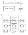
図1は、本形態におけるディスク・アレイ・システムの構成を模式的に示すブロック図である。図1の構成において、ホスト6は、ディスク・アレイ・システムに対してコマンドを発行することにより、データの書き込み/読み出しを行う。ディスク・アレイ・システムは、ホスト・インタフェース回路5、システム・コントローラ3、データ転送回路4、ドライブ・インタフェース回路2、そして複数のHDD1a〜1gを有している。
FIG. 1 is a block diagram schematically showing the configuration of a disk array system in this embodiment. In the configuration of FIG. 1, the host 6 writes / reads data by issuing a command to the disk array system. The disk array system has a host interface circuit 5, a
システム・コントローラ3は、ホスト・インタフェース回路5を介して、ホスト6からコマンドを受信し、ディスク・アレイ・システムの各要素を制御することで、HDD1a〜1gへのデータの書き込み及び読み出しを制御する。ライト処理において、ホスト6からデータは、転送回路4及びドライブ・インターフェース回路2を介して、HDD1a〜1gに書き込まれる。また、リード処理においては、HDD1a〜1gから読み出されたユーザ・データは、ドライブ・インターフェース回路2及び転送回路4を介してホスト6に転送される。
The
HDD1a〜1gは、RAID(Redundant Array Inexpensive Disks)構成となるように接続されている。図1の構成においては、HDD1a〜HDD1cが一つのRAIDグループを構成し、HDD1d〜HDD1fが他の一つのRAIDグループを構成し、さらに、HDD1g〜HDD1iが他の一つのRAIDグループを構成している。システム・コントローラ3は、ホスト6から転送されたユーザ・データを複数のデータ・ブロックに分割し(ストライピング)、一つのRAIDグループ内の各HDDに振り分けて格納する。
The
本形態において、各RAIDグループには、プライオリティ・レベルが付されている。具体的には、HDD1a〜HDD1cのRAIDグループはハイ・プライオリティが与えられ、HDD1d〜HDD1fのRAIDグループはミドル・プライオリティが与えられ、HDD1g〜HDD1iのRAIDグループはロー・プライオリティが与えられている。ホスト6から転送されるユーザ・データにプライオリティ・レベルが付され、そのプライオリティ・レベルと合致するRAIDグループに格納される。 In this embodiment, each RAID group is assigned a priority level. Specifically, the RAID groups of HDD1a to HDD1c are given high priority, the RAID groups of HDD1d to HDD1f are given middle priority, and the RAID groups of HDD1g to HDD1i are given low priority. The user data transferred from the host 6 is given a priority level and stored in a RAID group that matches the priority level.
ユーザ・データをいずれのプライオリティ・レベルのRAIDに格納するかを決定するのは、システム・コントローラ3であってもよいしホスト6であってもよい。図1の構成例においては、一つのRAIDグループに一つのプライオリティ・レベルが割り当てられているが、複数のRAIDグループに一つのプライオリティ・レベルを割り当ててもよい。ユーザ・データは、同一のプライオリティ・レベルのRAIDグループに格納する、あるいは、ユーザ・データのプライオリティ・レベル以上のレベルを有するRAIDグループに格納するようにしてもよい。
The
本形態のRAIDシステムにおいて、HDD1a〜1iは、そのプライオリティ・レベルに応じたスピン・アップ・モードが設定されている。スピン・アップは、HDDのスピンドル・モータ(磁気ディスク)の回転速度を、データ・アクセスのための回転速度まで上げるオペレーションである。好ましい態様において、HDD1a〜1iは、電源投入からのスピン・アップと、パワー・セーブ・モードからのスピン・アップのモードとを、個別に設定することができる。これにより、HDD1a〜1iが実装されているシステムに応じてより適切にスピンドル・モータのスピン・アップを制御することができる。
In the RAID system of the present embodiment, the
また、好ましい態様において、HDD1a〜1gにおけるスピン・アップにおける最大電流(スピン・アップ電流)が、スピンアップ・モードにおいて設定可能な可変数となっている。スピン・アップ電流が大きいほど、スピンドル・モータの回転速度をより早く所定の回転速度まで上げることができる。つまり、ディスク・アクセスまでの待ち時間をより短縮することができる。一方、スピン・アップ電流が大きいとピーク電力が増加し、システム電源への負担が大きくなる。
In a preferred embodiment, the maximum current (spin-up current) in the spin-up in the
このように、好ましい態様のHDD1a〜1iは、そのプライオリティ・レベルに応じて、電源投入からのスピン・アップに加え、パワー・セーブ・モードからのスピン・アップにおけるスピン・アップ電流を設定することができる。パワー・セーブ・モードにおいて、HDD1a〜1iの電源はONであるが、スピンドル・モータの回転が停止している、あるいは、スピンドル・モータがデータ・アクセスにおける回転速度よりも遅い速度で回転している。このように、電源投入からのスピン・アップとパワー・セーブ・モードからのスピン・アップのそれぞれのスピン・アップ電流を設定可能とすることで、HDD1a〜1gが実装されているシステムに応じてより適切にスピンドル・モータのスピン・アップを制御することができる。
As described above, the
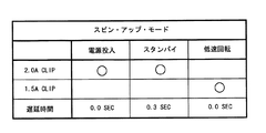
図2(a)は、HDD1a〜1iの好ましいスピン・アップ・モード設定の一例を示している。HDD1a〜1iは、二つのパワー・セーブ・モードを有している。第1のパワー・セーブ・モードはスタンバイ・モードであり、そのモードにおいて、HDD1a〜1iはスピンドル・モータの回転を停止する。第2のパワー・セーブ・モードは低速回転モードであり、スピンドル・モータは回転しているが、その回転速度はヘッドが磁気ディスクにアクセスするときの回転速度よりも遅い。第1のパワー・セーブ・モードがより大きな消費電力低減を行うことができるが、スピン・アップを開始してからレディになるまでより時間が必要である。
FIG. 2A shows an example of a preferable spin-up mode setting of the
図2(a)の例において、2.0Aと1.5Aの二つのスピン・アップ最大電流がHDD1a〜1gに設定されている。図2(b)に示すように、スピン・アップにおけるVCM電流の大きさは、0Aから急激に最大電流2.0Aあるいは1.5Aまで増加し、その後、所定期間最大電流値に維持される。スピンドル・モータの回転速度が特定の速度に達する、あるいはスピン・アップ開始から特定時間が経過すると、その後は、PID制御に移行しVCM電流の大きさは減少する。
In the example of FIG. 2A, two spin-up maximum currents of 2.0A and 1.5A are set in the
図2(a)の例では、ハイ・プライオリティのHDD1a〜HDD1cは、電源投入と第1及び第2のパワー・セーブ・モードからのスピン・アップの、全てのスピン・アップにおいて、2.0Aの最大スピンアップ電流をスピンドル・モータに与える。一方、ロー・プライオリティのHDD1g〜HDD1iは、全てのスピン・アップにおいて、1.5Aの最大スピンアップ電流をスピンドル・モータに与える。ミドル・プライオリティのHDD1d〜HDD1fは、低速回転からのスピン・アップにおいて1.5Aの最大スピンアップ電流をスピンドル・モータに与え、他のスピン・アップにおいて2.0Aの最大スピンアップ電流をスピンドル・モータに与える。
In the example of FIG. 2A, the high-
プライオリティが高いデータは、それだけ速いアクセスが要求される。そのため、高いプライオリティのデータを格納しているHDDのスピン・アップを早め、低いプライオリティのデータを格納するHDDのスピン・アップ最大電流を小さくすることで、システム全体としてのパフォーマンスと電源負荷の低減を図ることができる。また、低速回転のパワー・セーブ・モードからの復帰では、レディになるまでの時間は停止状態からのスピン・アップよりも短い。そのため、ミドル・プライオリティのHDD1d〜HDD1fは、低速回転からのスピン・アップにおいて1.5Aの最大スピンアップ電流をスピンドル・モータに与えて、パフォーマンスと電源負荷の低減を図る。
Higher priority data requires faster access. For this reason, the performance and power load of the entire system can be reduced by accelerating the spin-up of HDDs storing high priority data and reducing the maximum spin-up current of HDDs storing low priority data. Can be planned. Also, when returning from the low-speed rotation power save mode, the time until becoming ready is shorter than the spin-up from the stop state. Therefore, the
HDDが複数のパワー・セーブ・モードを有している場合、それぞれのパワー・セーブ・モードについて、個別にスピン・アップ最大電流を設定することで、システムへの適応性を高めることができる。一方、HDDの設定及び制御のシンプリシティの点から、スピン・アップ最大電流の設定を電源投入とパワー・セーブ・モードからの復帰の二つに分類し、複数のパワー・セーブ・モードに対して一つのスピン・アップ最大電流を設定可能とするようにしてもよい。 When the HDD has a plurality of power save modes, the adaptability to the system can be enhanced by setting the spin-up maximum current individually for each power save mode. On the other hand, from the viewpoint of HDD setting and control simplicity, the spin-up maximum current setting is classified into power-on and return from power-save mode. Two maximum spin-up currents may be settable.
好ましい態様において、スピン・アップ・モードは、設定可能な変数として、スピン・アップ開始の遅延時間を有している。HDD1a〜1iは、電源投入あるいはパワー・セーブ・モードからの復帰処理を開始してから、設定されている遅延時間が経過した後にスピンドル・モータのスピン・アップを開始する。このように、HDD毎にスピン・アップ開始遅延時間を設定可能とすることで、システム・コントローラ3が制御することなく、システム全体のピーク電流低減とパフォーマンス維持とを図ることができる。
In a preferred embodiment, the spin-up mode has a spin-up start delay time as a configurable variable. The
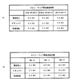
図3(a)、(b)は、HDD1a〜1iのスピン・アップ開始遅延時間の設定例を示している。図3(a)の設定例においては、同一プライオリティ・レベルの全てのHDDに対して同一の設定がなされている。また、電源投入からのスピン・アップにおいては、全てのHDD1a〜1iに同一遅延時間が設定される。具体的には、電源投入からのスピン・アップにおいては、全てのHDD1a〜1iに0.0秒の遅延時間が設定されている。スタンバイ・モードからのスピン・アップにおいては、プライオリティ・ハイ、ミドルそしてローのそれぞれのグループのHDDに対して、0.0秒、0.3秒そして0.6秒の遅延時間が設定されている。低速回転のパワー・セーブ・モードからのスピン・アップの設定は、スタンバイ・モードからのスピン・アップと同じである。
3A and 3B show setting examples of the spin-up start delay times of the
このように、プライオリティ・レベルに応じてHDD1a〜1iのスピン・アップ開始時間を調整することは、システムの全HDDのパワー・セーブ・モードの制御を同時に行うシステムにおいて特に有用である。システム全体のピーク電流を少なくしながら、プライオリティ・レベルの高いHDDは、より早くレディ状態にすることができる。図3(a)の設定例にも示すように、遅延時間は、スピン・アップを開始のモード(電源投入あるいはいずれかのパワー・セーブ・モード)及びプライオリティに応じて適切な値を選択し、異なるプライオリティ・グループが同一の遅延時間設定を有していてもよい。
As described above, adjusting the spin-up start time of the
図3(b)の設定例においては、同一プライオリティ・レベルのグループに属するHDDが、異なる遅延時間の設定を有している。図3(b)は、ミドル・プライオリティ・グループのHDD1d〜HDDfの設定例を示している。この設定例においては、全てのHDD1d〜HDDfに異なる遅延時間が設定されている。このように、同一プライオリティ・グループのHDDに対して異なる遅延時間を設定することで、同一プライオリティ・グループのHDDのパワー・セーブ・モードの制御を同時に行うシステムにおいてシステム全体のピーク電流を少なくすることができる。なお、同一グループの一部のHDDが同一の遅延時間設定を有していてもよい。 In the setting example of FIG. 3B, HDDs belonging to the group having the same priority level have different delay times. FIG. 3B shows a setting example of HDDs 1d to HDDf of the middle priority group. In this setting example, different delay times are set for all the HDDs 1d to HDDf. In this way, by setting different delay times for HDDs in the same priority group, the peak current of the entire system can be reduced in a system that simultaneously controls the power save mode of HDDs in the same priority group. Can do. Note that some HDDs in the same group may have the same delay time setting.
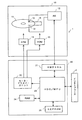
このように、本形態のHDDは、実装されるシステムに応じたスピン・アップ・モードの設定を行うことができる。以下においては、HDDのスピン・アップ・モードの設定方法及びその設定に従ったHDDのオペレーションについて、具体的に説明する。図4は、HDD1の全体構成を模式的に示すブロック図である。HDD1は、エンクロージャ10の外側に固定された回路基板20を有している。回路基板20上に、リード・ライト・チャネル(RWチャネル)21、モータ・ドライバ・ユニット22、ハードウェアであるハードディスク・コントローラ(HDC)とMPUの集積回路(HDC/MPU)23及びRAM24などの各回路が実装されている。
As described above, the HDD according to the present embodiment can set the spin-up mode according to the installed system. The HDD spin-up mode setting method and the HDD operation according to the setting will be specifically described below. FIG. 4 is a block diagram schematically showing the overall configuration of the
エンクロージャ10内において、スピンドル・モータ(SPM)14は所定の角速度で磁気ディスク11を回転する。磁気ディスク11は、データを記憶するメディアである。HDC/MPU23からの制御データに従って、モータ・ドライバ・ユニット22がSPM14を駆動する。各ヘッド・スライダ12は、磁気ディスク上を浮上するスライダと、スライダに固定され磁気信号と電気信号との間の変換(データの読み書き)を行うヘッド素子部とを備えている。各ヘッド・スライダ12はアクチュエータ16の先端部に固定されている。アクチュエータ16はボイス・コイル・モータ(VCM)15に連結され、回動軸を中心に回動することによって、ヘッド・スライダ12を回転する磁気ディスク11上においてその半径方向に移動する。
Within the
モータ・ドライバ・ユニット22は、HDC/MPU23からの制御データに従ってVCM15を駆動する。アーム電子回路(AE:Arm Electronics)13は、HDC/MPU23からの制御データに従って複数のヘッド・スライダ12の中から磁気ディスク11にアクセス(リードもしくはライト)するヘッド・スライダ12を選択し、リード/ライト信号の増幅を行う。
The
RWチャネル21は、リード処理において、AE13から供給されたリード信号を一定の振幅となるように増幅し、その後、取得したリード信号からデータを抽出し、デコード処理を行う。デコード処理されたデータは、HDC/MPU23に供給される。また、RWチャネル21は、ライト処理において、HDC/MPU23から供給されたライト・データをコード変調し、さらに、コード変調されたデータをライト信号に変換してAE13に供給する。
In the read process, the
コントローラの一例であるHDC/MPU23において、MPU23は、磁気ディスク11あるいはEEPROM25からRAM24あるいはHDC内のSRAMにロードされたファーム・ウェアに従って動作する。HDC/MPU23は、リード/ライト処理制御、コマンド実行順序の管理、サーボ信号を使用したヘッド・ポジショニング制御(サーボ制御)、ホスト51との間のインターフェース制御、ディフェクト管理、エラー対応処理など、データ処理に関する必要な処理及びHDD1の全体制御を実行する。
In the HDC /
本形態において、HDC/MPU23は、特に、設定データに従ったスピン・アップ制御を行う。適系的には、MPUがファームウェアと設定データに従ってスピン・アップ制御を行う。上述のように、モータ・ドライバ・ユニット22がSPM13に電流を供給して駆動する。モータ・ドライバ・ユニット22は、HDC/MPU23から得た制御データに従って、SPM13に電流を供給する。
In this embodiment, the HDC /
SPM13のスピン・アップ・オペレーションにおいても、それは同様である。HDC/MPU23は、モータ・ドライバ・ユニット22に対して、設定されているスピン・アップ・モードに対応するスピン・アップ・プロファイルを規定するデータを渡す。モータ・ドライバ・ユニット22は、そのプロファイルに従ってSPM13のスピン・アップを行う。
The same applies to the spin-up operation of SPM13. The HDC /
HDC/MPU23が渡すスピン・アップ・プロファイルは、スピン・アップにおける最大電流値のほか、SPM13のフィード・バック制御におけるパラメータ、さらに、フィード・バック制御に移行するまでの時間や回転速度などの情報を含む。モータ・ドライバ・ユニット22は、HDC/MPU23からの指示により、スピン・アップを開始する。従って、HDC/MPU23は、設置データの遅延時間に従ったタイミングで、モータ・ドライバ・ユニット22に対してスピン・アップの開始を指示する。
The spin-up profile handed over by the HDC /
図5は、HDD1内に保存されている設定データの一例を示している。電源投入後のスピン・アップ前に磁気ディスク11にアクセスすることはできないため、設定データは、不揮発性メモリであるEEPROM25内に格納されている。HDC/MPU23は、電源投入後にEEPROM25から設定データを取得し、DRAM24もしくはSRAMに格納する。図5に示す設定データ例は、スピン・アップ最大電流値とスピン・アップ開始遅延時間の双方を特定している。
FIG. 5 shows an example of setting data stored in the
HDC/MPU23は、電源投入後のスピン・アップのため、モータ・ドライバ・ユニット22に対して、2.0Aの電流値を含むスピン・アップ・プロファイルデータを渡し、さらに、スピン・アップの開始を指示する。低速回転もパワー・セーブ・モードからのスピン・アップにおいては、モータ・ドライバ・ユニット22に対して1.5Aの電流値を含むスピン・アップ・プロファイル・データを渡し、さらに、スピン・アップの開始を指示する。
The HDC /
スタンバイ・モードからのスピン・アップにおいて、HDC/MPU23は、遅延時間の設定データに従って、0.3秒の経過を待って、モータ・ドライバ・ユニット22に対して、2.0Aの電流値を含むスピン・アップ・プロファイル・データを渡し、さらに、スピン・アップの開始を指示する。あるいは、HDC/MPU23は、先にスピン・アップ・プロファイルを渡した後に、遅延時間が経過してからスピン・アップ開始を指示してもよい。
In the spin-up from the standby mode, the HDC /
HDC/MPU23は、電源が投入されると、HDD1の起動処理を開始する。その起動処理において、上記スピン・アップ処理も行われる。一方、スタンバイ・モードや低回転モードからレディ状態(通常状態)への復帰処理を、HDC/MPU23は、HDD1にとってのホスト装置であるシステム・コントローラ3からのコマンドに応じて開始する。HDC/MPU23は、システム・コントローラ3からコマンドを受信してから、設定されている遅延時間が経過した後に、スピン・アップ開始をモータ・ドライバ・ユニット22に指示する。HDC/MPU23は、レディ状態からパワー・セーブ・モードへの移行も、システム・コントローラ3からのコマンドにより行う。
The HDC /
あるいは、HDC/MPU23は、内部制御処理として、パワー・セーブ・モードへの移行及びパワー・セーブ・モードから復帰を行ってもよい。例えば、システム・コントローラ3からのアクセスが規定時間を越えて存在していない場合、HDC/MPU23は、パワー・セーブ・モードに移行する。HDC/MPU23は、システム・コントローラ3からリード/ライトのコマンドを受信すると、パワー・セーブ・モードから復帰する。あるいは、HDC/MPU23が現在のモードをシステム・コントローラ3に予め報告しておくことで、システム・コントローラ3がパワー・セーブ・モードからの復帰をコマンドにより指示してもよい。
Alternatively, the HDC /
好ましくは、HDC/MPU23は、システム・コントローラ3からの復帰コマンドによらず、内部処理でパワー・セーブ・モードから復帰する場合、遅延時間の設定にかかわりなく、遅延なくSPM13のスピン・アップを開始する。システム・コントローラ3の管理下にない処理において、システム電源のピーク電流低減のために他のHDDのスピン・アップ・タイミングと同期することが難しいため、通常のスピン・アップによりパフォーマンスの低下を避ける。
Preferably, the HDC /
このように、それぞれのHDDが異なるスピン・アップ・モードを設定されている場合、それらを制御するシステム・コントローラ3が、各HDDの設定を知っておくことが好ましい。そのため、好ましい態様において、HDC/MPU23は、システム・コントローラ3に対して、自己のスピン・アップ・モード設定を通知する。この通知は、システム・コントローラ3からのコマンドに応答して、あるいは、電源投入における起動処理において自発的に行うことができる。
In this way, when each HDD is set to a different spin-up mode, it is preferable that the
システム・コントローラ3は、システムに内に接続されているHDD1a〜1iの設定データを取得し、それを管理テーブルに登録する。システム・コントローラ3は、HDD1a〜1iの電力制御(電源投入及びパワー・セーブ・モードからの復帰における電力制御)において、この管理テーブルを参照して、HDD1a〜1iの電源投入及びパワー・セーブ・モードからの復帰指示を行う。
The
HDD1のスピン・アップ・モードの設定の変更は、HDD1をシステムに実装する前あるいはシステムに実装した後に行う。例えば、HDD1の製造工程において、予めスピン・アップ・モード設定を登録する。システム設計者は、適切なスピン・アップ・モード設定のHDDを選択した、システムに実装する。あるいは、システム・コントローラ3はHDD1に対してコマンドにより、スピン・アップ・モードの設定を指示する。これにより、システム状況に応じたスピン・アップ・モードを設定することができる。この場合、システム・コントローラ3は各HDDのスピン・アップ・モードを管理テーブルに登録して、その後の処理で使用する。
The setting of the spin-up mode of the
以上、本発明を好ましい実施形態を例として説明したが、本発明が上記の実施形態に限定されるものではない。当業者であれば、上記の実施形態の各要素を、本発明の範囲において容易に変更、追加、変換することが可能である。例えば、本発明を、磁気ディスクと異なる記憶ディスクを有するディスク・ドライブに適用することができる。本発明は、ディスク・アレイ・システム及びそれに使用するディスク・ドライブに特に好適であるが、外部ストレージとして単独のディスク・ドライブを有するシステム及びそれに使用するディスク・ドライブにも適用することができる。 As mentioned above, although this invention was demonstrated taking preferable embodiment as an example, this invention is not limited to said embodiment. A person skilled in the art can easily change, add, and convert each element of the above-described embodiment within the scope of the present invention. For example, the present invention can be applied to a disk drive having a storage disk different from a magnetic disk. The present invention is particularly suitable for a disk array system and a disk drive used therefor, but can also be applied to a system having a single disk drive as an external storage and a disk drive used therefor.
スピン・アップ・モード設定において、最大電流と遅延時間の双方を設定できることが好ましいが、その一方のみを設定できるようにしてもよい。また、遅延時間の設定は、パワー・セーブ・モードのみにおいて行うことがでいるようにしてもよい。そのような場合、例えば、電源投入におけるスピン・アップ開始タイミングを、システム・コントローラの制御により対応することができる。 In the spin-up mode setting, it is preferable that both the maximum current and the delay time can be set, but only one of them may be set. The delay time may be set only in the power save mode. In such a case, for example, the spin-up start timing when the power is turned on can be handled by the control of the system controller.
1 ハード・ディスク・ドライブ、2 ドライブ・インターフェース回路
3 システム・コントローラ、4 データ転送回路、5 ホスト・インターフェース回路
6 ホスト装置、1、1a〜1i ハードディスク・ドライブ、10 エンクロージャ
11 磁気ディスク、12 ヘッド・スライダ
13 アーム・エレクトロニクス(AE)、14 スピンドル・モータ
15 ボイス・コイル・モータ、16 アクチュエータ、20 回路基板
21 リード・ライト・チャネル、22 モータ・ドライバ・ユニット
23 HDC/MPU、24 RAM、25 EEPROM
DESCRIPTION OF
Claims (13)
電源投入からの前記スピンドル・モータのスピン・アップ・モードの設定データと、パワー・セーブ・モードからの前記スピンドル・モータのスピン・アップ・モードを設定データと、を格納している不揮発性メモリと、
前記不揮発性メモリに格納されている設定データに従って、前記電源投入からの前記スピン・アップ及び前記パワー・セーブ・モードからの前記スピン・アップのそれぞれのモードを決定するコントローラと、
前記電源投入からの前記スピン・アップ及び前記パワー・セーブ・モードからの前記スピン・アップのそれぞれにおいて、前記コントローラが決定したモードにおいて前記スピンドル・モータをスピン・アップするモータ・ドライバと、
を有する、ディスク・ドライブ。 A spindle motor that rotates a disk that stores data; and
Non-volatile memory storing setting data for the spindle motor spin-up mode from power-on and setting data for the spindle motor spin-up mode from the power save mode; ,
A controller for determining respective modes of the spin-up from the power-on and the spin-up from the power-save mode according to setting data stored in the nonvolatile memory;
A motor driver that spins up the spindle motor in a mode determined by the controller in each of the spin up from the power on and the spin up from the power save mode;
Having a disk drive.
請求項1に記載のディスク・ドライブ。 In each of the spin-up mode from the power save mode and the spin-up mode from the power save mode, a spin-up maximum current can be set.
The disk drive of claim 1.
請求項1に記載のディスク・ドライブ。 In each of the spin-up modes from the power save mode, a spin-up start delay time can be set.
The disk drive of claim 1.
請求項1に記載のディスク・ドライブ。 The controller notifies the host of the determined spin-up mode from power-on and spin-up from the power save;
The disk drive of claim 1.
請求項1に記載のディスク・ドライブ。 The controller returns from the power save mode in response to a command from the host.
The disk drive of claim 1.
前記コントーラは、前記第1パワー・セーブ・モードと前記第2パワー・セーブ・モードのそれぞれについて、設定データに従ってスピン・アップ・モードを決定する、
請求項1に記載のディスク・ドライブ。 The disk drive has a first power save mode in which the spindle motor is stopped and a second power save mode in which the rotation of the spindle motor is reduced;
The controller determines a spin-up mode according to setting data for each of the first power save mode and the second power save mode.
The disk drive of claim 1.
前記コントローラが設定データに従って決定した一つのスピン・アップ・モードが前記第1パワー・セーブ・モードと前記第2パワー・セーブ・モードに対応づけられる、
請求項1に記載のディスク・ドライブ。 The disk drive has a first power save mode in which the spindle motor is stopped and a second power save mode in which the rotation of the spindle motor is reduced,
One spin-up mode determined by the controller according to setting data is associated with the first power save mode and the second power save mode.
The disk drive of claim 1.
ユーザ・データを分割し、分割したデータのそれぞれを前記複数のディスク・ドライブに格納することを指示するシステム・コントローラと、を有し、
前記複数のディスク・ドライブのそれぞれは、
電源投入からの前記スピンドル・モータのスピン・アップ・モードの設定データと、パワー・セーブ・モードからの前記スピンドル・モータのスピン・アップ・モードを設定データと、を格納している不揮発性メモリと、
前記不揮発性メモリに格納されている設定データに従って、前記電源投入からの前記スピン・アップ及び前記パワー・セーブ・モードからの前記スピン・アップのそれぞれのモードを決定するコントローラと、
前記電源投入からの前記スピン・アップ及び前記パワー・セーブ・モードからの前記スピン・アップのそれぞれにおいて、前記コントローラが決定したモードにおいて前記スピンドル・モータをスピン・アップするモータ・ドライバと、
を有する、ディスク・アレイ・システム。 Multiple disk drives;
A system controller that divides user data and directs each of the divided data to be stored in the plurality of disk drives;
Each of the plurality of disk drives is
Non-volatile memory storing setting data for the spindle motor spin-up mode from power-on and setting data for the spindle motor spin-up mode from the power save mode; ,
A controller for determining respective modes of the spin-up from the power-on and the spin-up from the power-save mode according to setting data stored in the nonvolatile memory;
A motor driver that spins up the spindle motor in a mode determined by the controller in each of the spin up from the power on and the spin up from the power save mode;
A disk array system.
請求項8に記載のディスク・アレイ・システム。 The controller shifts the spin-up timing of each of the plurality of disk drives when the power is turned on.
The disk array system according to claim 8.
請求項8に記載のディスク・アレイ・システム。 In the plurality of disk drives, a maximum spin-up current can be set in each of the spin-up mode from the power save mode and the spin-up mode from the power save mode. ,
The disk array system according to claim 8.
同一グループのディスク・ドライブにおける前記パワー・セーブ・モードからのスピン・アップ・モードと前記パワー・セーブ・モードからのスピン・アップ・モードのそれぞれのスピン・アップ最大電流の設定が同一である、
請求項10に記載のディスク・アレイ・システム。 The system controller divides the plurality of disk drives into a plurality of groups to control data storage;
The spin-up maximum current setting of each of the spin-up mode from the power save mode and the spin-up mode from the power save mode in the same group of disk drives is the same.
The disk array system according to claim 10.
請求項8に記載のディスク・アレイ・システム。 In the plurality of disk drives, the spin-up start delay time can be set in the spin-up mode from the spin-up mode from the power save mode.
The disk array system according to claim 8.
前記システム・コントローラは、前記複数のディスク・ドライブのスピン・アップ・モードを管理し、
前記複数のディスク・ドライブのスピン・アップ・モードに応じて、前記複数のディスク・ドライブのパワー・セーブ・モードからの復帰を制御する、
請求項8に記載のディスク・アレイ・システム。 The plurality of disk drives notify the system controller of the determined spin-up mode from power-on and the spin-up from the power save,
The system controller manages a spin up mode of the plurality of disk drives;
Controlling return of the plurality of disk drives from a power save mode in accordance with a spin up mode of the plurality of disk drives;
The disk array system according to claim 8.
Priority Applications (2)
| Application Number | Priority Date | Filing Date | Title |
|---|---|---|---|
| JP2008322245A JP2010146630A (en) | 2008-12-18 | 2008-12-18 | Disk drive and disk array system |
| US12/642,734 US8111476B2 (en) | 2008-12-18 | 2009-12-18 | Disk drive spin control |
Applications Claiming Priority (1)
| Application Number | Priority Date | Filing Date | Title |
|---|---|---|---|
| JP2008322245A JP2010146630A (en) | 2008-12-18 | 2008-12-18 | Disk drive and disk array system |
Publications (2)
| Publication Number | Publication Date |
|---|---|
| JP2010146630A true JP2010146630A (en) | 2010-07-01 |
| JP2010146630A5 JP2010146630A5 (en) | 2013-01-31 |
Family
ID=42265682
Family Applications (1)
| Application Number | Title | Priority Date | Filing Date |
|---|---|---|---|
| JP2008322245A Pending JP2010146630A (en) | 2008-12-18 | 2008-12-18 | Disk drive and disk array system |
Country Status (2)
| Country | Link |
|---|---|
| US (1) | US8111476B2 (en) |
| JP (1) | JP2010146630A (en) |
Cited By (1)
| Publication number | Priority date | Publication date | Assignee | Title |
|---|---|---|---|---|
| WO2013076974A1 (en) * | 2011-11-24 | 2013-05-30 | パナソニック株式会社 | Drive device |
Families Citing this family (21)
| Publication number | Priority date | Publication date | Assignee | Title |
|---|---|---|---|---|
| JP5131243B2 (en) * | 2009-05-11 | 2013-01-30 | 富士通株式会社 | Transmission apparatus and transmission apparatus pause method |
| KR20110029312A (en) * | 2009-09-15 | 2011-03-23 | 삼성전자주식회사 | Spin-up Control System and Method of Storage Device |
| US8615622B2 (en) | 2010-06-23 | 2013-12-24 | International Business Machines Corporation | Non-standard I/O adapters in a standardized I/O architecture |
| US8645606B2 (en) | 2010-06-23 | 2014-02-04 | International Business Machines Corporation | Upbound input/output expansion request and response processing in a PCIe architecture |
| US8745292B2 (en) | 2010-06-23 | 2014-06-03 | International Business Machines Corporation | System and method for routing I/O expansion requests and responses in a PCIE architecture |
| US8417911B2 (en) | 2010-06-23 | 2013-04-09 | International Business Machines Corporation | Associating input/output device requests with memory associated with a logical partition |
| US8656228B2 (en) | 2010-06-23 | 2014-02-18 | International Business Machines Corporation | Memory error isolation and recovery in a multiprocessor computer system |
| US8645767B2 (en) | 2010-06-23 | 2014-02-04 | International Business Machines Corporation | Scalable I/O adapter function level error detection, isolation, and reporting |
| US8677180B2 (en) | 2010-06-23 | 2014-03-18 | International Business Machines Corporation | Switch failover control in a multiprocessor computer system |
| US8671287B2 (en) * | 2010-06-23 | 2014-03-11 | International Business Machines Corporation | Redundant power supply configuration for a data center |
| US8416834B2 (en) | 2010-06-23 | 2013-04-09 | International Business Machines Corporation | Spread spectrum wireless communication code for data center environments |
| US8615586B2 (en) | 2010-06-23 | 2013-12-24 | International Business Machines Corporation | Discovery of logical images at storage area network endpoints |
| US8918573B2 (en) | 2010-06-23 | 2014-12-23 | International Business Machines Corporation | Input/output (I/O) expansion response processing in a peripheral component interconnect express (PCIe) environment |
| US8694811B2 (en) * | 2010-10-29 | 2014-04-08 | Texas Instruments Incorporated | Power management for digital devices |
| US8743502B1 (en) | 2010-12-17 | 2014-06-03 | Western Digital Technologies, Inc. | Disk drive spinning down disk to a spin rate based on spin-up parameter |
| EP2674851B1 (en) * | 2011-02-10 | 2018-01-17 | Fujitsu Limited | Storage control device, storage device, storage system, storage control method, and program for same |
| US8630056B1 (en) | 2011-09-12 | 2014-01-14 | Western Digital Technologies, Inc. | Hybrid drive adjusting spin-up profile based on cache status of non-volatile semiconductor memory |
| US9047201B2 (en) * | 2011-12-25 | 2015-06-02 | Synology Incorporated | Method for waking up a plurality of hibernated mass storage devices |
| US9564186B1 (en) * | 2013-02-15 | 2017-02-07 | Marvell International Ltd. | Method and apparatus for memory access |
| US10229710B2 (en) | 2015-05-05 | 2019-03-12 | Seagate Technology Llc | Motor spin up with auxiliary power boost |
| US9653110B2 (en) * | 2015-06-15 | 2017-05-16 | Quanta Computer, Inc. | Speed control of data storage device using service controller |
Citations (14)
| Publication number | Priority date | Publication date | Assignee | Title |
|---|---|---|---|---|
| JPH0411353A (en) * | 1990-04-27 | 1992-01-16 | Matsushita Electric Ind Co Ltd | Magnetic disk device |
| JPH0492254A (en) * | 1990-08-08 | 1992-03-25 | Hitachi Ltd | hard disk storage device |
| JPH04139524A (en) * | 1990-10-01 | 1992-05-13 | Hitachi Ltd | Array disk device and its control method |
| JPH04205963A (en) * | 1990-11-30 | 1992-07-28 | Fujitsu Ltd | Disk device |
| JPH0644678A (en) * | 1992-07-28 | 1994-02-18 | Fujitsu Ltd | Start control method for motor of disk device |
| JPH06314464A (en) * | 1993-02-23 | 1994-11-08 | Toshiba Corp | Disk subsystem startup method |
| JPH07334950A (en) * | 1994-06-07 | 1995-12-22 | Hitachi Ltd | Disk device |
| JPH087450A (en) * | 1994-06-22 | 1996-01-12 | Toshiba Corp | Data recording / reproducing apparatus and motor control method thereof |
| JPH08102132A (en) * | 1994-09-30 | 1996-04-16 | Toshiba Corp | Information recording device |
| JPH08167225A (en) * | 1994-12-08 | 1996-06-25 | Hitachi Ltd | Information storage device |
| JPH08287583A (en) * | 1995-04-13 | 1996-11-01 | Internatl Business Mach Corp <Ibm> | System and method for electric power management of disk driving device |
| JPH1083614A (en) * | 1996-07-18 | 1998-03-31 | Hitachi Ltd | Method of controlling magnetic disk device, method of controlling disk array device, and disk array device |
| JP2000293314A (en) * | 1999-04-05 | 2000-10-20 | Hitachi Ltd | Disk array device |
| JP2007293479A (en) * | 2006-04-24 | 2007-11-08 | Hitachi Ltd | Computer system and method for reducing power consumption of storage system |
Family Cites Families (12)
| Publication number | Priority date | Publication date | Assignee | Title |
|---|---|---|---|---|
| JPH0793058A (en) * | 1993-09-28 | 1995-04-07 | Fujitsu Ltd | I / O device power control device |
| JP3263556B2 (en) | 1995-02-28 | 2002-03-04 | 三洋電機株式会社 | Drive circuit |
| US5682273A (en) * | 1995-06-30 | 1997-10-28 | International Business Machines Corporation | Disk drive for portable computer with adaptive demand-driven power management |
| JP2002032952A (en) | 2000-07-18 | 2002-01-31 | Matsushita Electric Ind Co Ltd | Motor start method |
| US7007141B2 (en) * | 2001-01-30 | 2006-02-28 | Data Domain, Inc. | Archival data storage system and method |
| JP3456208B2 (en) | 2001-07-18 | 2003-10-14 | 株式会社日立製作所 | Control method of magnetic disk drive and magnetic disk drive adaptive to power environment |
| US7332883B1 (en) * | 2005-06-17 | 2008-02-19 | Marvell International Ltd. | Method and apparatus for initializing operation of a disk drive |
| US7221531B2 (en) * | 2005-09-12 | 2007-05-22 | Intel Corporation | Staggered spin-up disable mechanism |
| JP4824374B2 (en) * | 2005-09-20 | 2011-11-30 | 株式会社日立製作所 | System that controls the rotation of the disc |
| JP2007156089A (en) | 2005-12-05 | 2007-06-21 | Fuji Xerox Co Ltd | Image forming apparatus and motor control apparatus |
| US7853809B2 (en) * | 2007-01-11 | 2010-12-14 | Seagate Technology Llc | System and method of power management |
| JP2009211510A (en) * | 2008-03-05 | 2009-09-17 | Hitachi Ltd | Disk array device |
-
2008
- 2008-12-18 JP JP2008322245A patent/JP2010146630A/en active Pending
-
2009
- 2009-12-18 US US12/642,734 patent/US8111476B2/en not_active Expired - Fee Related
Patent Citations (14)
| Publication number | Priority date | Publication date | Assignee | Title |
|---|---|---|---|---|
| JPH0411353A (en) * | 1990-04-27 | 1992-01-16 | Matsushita Electric Ind Co Ltd | Magnetic disk device |
| JPH0492254A (en) * | 1990-08-08 | 1992-03-25 | Hitachi Ltd | hard disk storage device |
| JPH04139524A (en) * | 1990-10-01 | 1992-05-13 | Hitachi Ltd | Array disk device and its control method |
| JPH04205963A (en) * | 1990-11-30 | 1992-07-28 | Fujitsu Ltd | Disk device |
| JPH0644678A (en) * | 1992-07-28 | 1994-02-18 | Fujitsu Ltd | Start control method for motor of disk device |
| JPH06314464A (en) * | 1993-02-23 | 1994-11-08 | Toshiba Corp | Disk subsystem startup method |
| JPH07334950A (en) * | 1994-06-07 | 1995-12-22 | Hitachi Ltd | Disk device |
| JPH087450A (en) * | 1994-06-22 | 1996-01-12 | Toshiba Corp | Data recording / reproducing apparatus and motor control method thereof |
| JPH08102132A (en) * | 1994-09-30 | 1996-04-16 | Toshiba Corp | Information recording device |
| JPH08167225A (en) * | 1994-12-08 | 1996-06-25 | Hitachi Ltd | Information storage device |
| JPH08287583A (en) * | 1995-04-13 | 1996-11-01 | Internatl Business Mach Corp <Ibm> | System and method for electric power management of disk driving device |
| JPH1083614A (en) * | 1996-07-18 | 1998-03-31 | Hitachi Ltd | Method of controlling magnetic disk device, method of controlling disk array device, and disk array device |
| JP2000293314A (en) * | 1999-04-05 | 2000-10-20 | Hitachi Ltd | Disk array device |
| JP2007293479A (en) * | 2006-04-24 | 2007-11-08 | Hitachi Ltd | Computer system and method for reducing power consumption of storage system |
Cited By (1)
| Publication number | Priority date | Publication date | Assignee | Title |
|---|---|---|---|---|
| WO2013076974A1 (en) * | 2011-11-24 | 2013-05-30 | パナソニック株式会社 | Drive device |
Also Published As
| Publication number | Publication date |
|---|---|
| US8111476B2 (en) | 2012-02-07 |
| US20100157463A1 (en) | 2010-06-24 |
Similar Documents
| Publication | Publication Date | Title |
|---|---|---|
| JP2010146630A (en) | Disk drive and disk array system | |
| KR101379493B1 (en) | Lowest power mode for a mobile drive in usb application | |
| US9117482B1 (en) | Hybrid drive changing power mode of disk channel when frequency of write data exceeds a threshold | |
| CN101114492B (en) | Disk drive with nonvolatile memory having multiple modes of operation | |
| US7853809B2 (en) | System and method of power management | |
| US20050174678A1 (en) | Stepping power consumption levels in a hard disk drive to maximize performance while minimizing power consumption | |
| JP2009020986A (en) | Disk drive device and method for storing table for managing data on non-volatile semiconductor memory area in disk drive device | |
| JP2007200537A (en) | Hybrid disk drive and data control method for hybrid disk drive | |
| US20050144491A1 (en) | Variable power consumption levels in a hard disk drive | |
| US7949795B2 (en) | Power conservation in data storage device by only starting the active state when the measured time indicates data is present on the interface | |
| JP2012234609A (en) | Data storage method and hybrid data storage device | |
| US10318173B2 (en) | Multi-speed data storage device with media cache for high speed writes | |
| JP2002298307A (en) | Data storage device, write current control circuit and write circuit control method | |
| JP2008204574A (en) | Storage device and control method thereof | |
| US7072138B2 (en) | Apparatus for optimizing processor clock frequency in a hard disk drive to minimize power consumption while maximizing performance | |
| WO2007103358A2 (en) | Lowest power mode for a mobile drive in usb application | |
| US8259407B1 (en) | Speed control systems and methods for decreasing power consumption in rotating storage devices | |
| US7095201B1 (en) | Method and apparatus for providing a user selectable start-up current in a disk drive | |
| JPH0492254A (en) | hard disk storage device | |
| US8082409B2 (en) | Data storage device and data management method in data storage device | |
| JPH08102132A (en) | Information recording device | |
| WO2008039235A1 (en) | Accessing a disk drive at multiple speeds | |
| US20100017633A1 (en) | Memory device, control device for memory device, and control method for memory device | |
| US20140068178A1 (en) | Write performance optimized format for a hybrid drive | |
| US20260086727A1 (en) | Methods for reducing time to resume data operations in spun down hard drives |
Legal Events
| Date | Code | Title | Description |
|---|---|---|---|
| RD04 | Notification of resignation of power of attorney |
Free format text: JAPANESE INTERMEDIATE CODE: A7424 Effective date: 20100510 |
|
| A521 | Request for written amendment filed |
Free format text: JAPANESE INTERMEDIATE CODE: A523 Effective date: 20111118 |
|
| A621 | Written request for application examination |
Free format text: JAPANESE INTERMEDIATE CODE: A621 Effective date: 20111118 |
|
| A521 | Request for written amendment filed |
Free format text: JAPANESE INTERMEDIATE CODE: A523 Effective date: 20121212 |
|
| A131 | Notification of reasons for refusal |
Free format text: JAPANESE INTERMEDIATE CODE: A131 Effective date: 20130115 |
|
| A601 | Written request for extension of time |
Free format text: JAPANESE INTERMEDIATE CODE: A601 Effective date: 20130411 |
|
| A602 | Written permission of extension of time |
Free format text: JAPANESE INTERMEDIATE CODE: A602 Effective date: 20130416 |
|
| A521 | Request for written amendment filed |
Free format text: JAPANESE INTERMEDIATE CODE: A523 Effective date: 20130514 |
|
| A02 | Decision of refusal |
Free format text: JAPANESE INTERMEDIATE CODE: A02 Effective date: 20131029 |