JP2010146032A - Mobile terminal device and display control method - Google Patents
Mobile terminal device and display control method Download PDFInfo
- Publication number
- JP2010146032A JP2010146032A JP2008009172A JP2008009172A JP2010146032A JP 2010146032 A JP2010146032 A JP 2010146032A JP 2008009172 A JP2008009172 A JP 2008009172A JP 2008009172 A JP2008009172 A JP 2008009172A JP 2010146032 A JP2010146032 A JP 2010146032A
- Authority
- JP
- Japan
- Prior art keywords
- display
- terminal device
- mobile terminal
- unit
- control unit
- Prior art date
- Legal status (The legal status is an assumption and is not a legal conclusion. Google has not performed a legal analysis and makes no representation as to the accuracy of the status listed.)
- Granted
Links
Images


Landscapes
- Position Input By Displaying (AREA)
- User Interface Of Digital Computer (AREA)
- Telephone Function (AREA)
Abstract
Description
本発明は、タッチパネルやタッチパッドを備えた携帯端末装置に関し、特に、装置利用者によるタッチパネルの操作性を向上させるための携帯端末装置に関する。 The present invention relates to a mobile terminal device including a touch panel and a touch pad, and more particularly to a mobile terminal device for improving the operability of a touch panel by a device user.
携帯電話、PDA(Personal Digital Assistant)に代表される携帯端末装置の中には、タッチパネルやタッチパッドを備えるものがある。ここでは、タッチパネルは、装置利用者が押下した位置を検出する各種方式(例えば、静電容量方式、抵抗膜方式、または赤外線遮光方式など)のセンサと当該センサの下面に配置されるディスプレイとを含んで構成されるデバイスを指すものとし、タッチパッドは、上記センサを含んで構成される、ディスプレイとの位置関係が制約されないポインティングデバイスを指すものとして、区別する。タッチパネルやタッチパッドを備えた携帯端末装置は、装置利用者に直感的な操作を提供することができる。 Some portable terminal devices represented by mobile phones and PDAs (Personal Digital Assistants) include a touch panel and a touch pad. Here, the touch panel includes a sensor of various methods (for example, a capacitance method, a resistance film method, or an infrared light shielding method) that detects a position pressed by the user of the device and a display disposed on the lower surface of the sensor. The touch pad is distinguished as a pointing device that includes the sensor and is not restricted in positional relationship with the display. A portable terminal device provided with a touch panel and a touch pad can provide an intuitive operation to the device user.
例えば、特許文献1には、携帯端末装置を片手で保持するとともに、その手でタッチパッドを操作することを実現する携帯端末装置が開示されている。
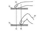
図8に、特許文献1の携帯端末装置の正面図(a)と背面図(b)を示す。特許文献1の携帯端末装置は、一つの面にディスプレイ81が、その面の背面にタッチパッド82が、それぞれ設けられている。ここでは、ディスプレイ81が設けられた面を正面、タッチパッド82が設けられた面を背面としている。図8では、装置利用者は、左手で携帯端末装置を保持しており、人差し指83の先端をタッチパッド82に接触させることによって操作を行っている。タッチパッド82のうち、人差し指83を完全に伸ばしても届かない領域に配置されたものは、片手操作性が非常に低い。
FIG. 8 shows a front view (a) and a rear view (b) of the portable terminal device of Patent Document 1. FIG. In the portable terminal device of Patent Document 1, a
また、図8のように携帯端末装置を片手で保持しつつ、その手の指の先端をタッチパッドに接触させる場合、図9の下段に示す場合にタッチパッドによる操作性が低下する場合がある。すなわち、図9の上段に示すように、タッチパッド82における、人差し指83の根元から離れた箇所(点線8aで示す箇所)に人差し指83の先端を接触させる場合には、装置利用者は人差し指83をそれほど折り曲げることなく楽な姿勢で操作することができるが、他方、図9の下段に示すように、タッチパッド82における、人差し指83の根元に近い箇所(点線8bで示す箇所)に人差し指83の先端を接触させる場合には、装置利用者は人差し指83を大きく折り曲げねばならず、窮屈な姿勢での操作を強いられる。点線8bで示す箇所を上記楽な姿勢で操作するためには、装置利用者は携帯端末装置を持ち直す必要があるが、タッチパッド82を操作する度に携帯端末装置を装置利用者に持ち直させることは好ましい操作性ではない。なお、操作性のよいタッチパネルやタッチパッドの形態は、タッチパネルやタッチパッドを備える携帯端末装置のサイズや形状などに依存する。
Further, when the portable terminal device is held with one hand as shown in FIG. 8 and the tip of the finger of the hand is brought into contact with the touchpad, the operability by the touchpad may be lowered in the case shown in the lower part of FIG. . That is, as shown in the upper part of FIG. 9, when the tip of the
本発明は、上記事情に鑑みてなされたもので、携帯端末装置を片手で保持するとともにその手でタッチパネルやタッチパッドを操作する場合に、その操作性を向上させることができる携帯端末装置、及び表示制御方法を提供することを目的とする。 The present invention has been made in view of the above circumstances. A portable terminal device that can improve the operability when holding the portable terminal device with one hand and operating a touch panel or a touchpad with the hand, and An object is to provide a display control method.
本発明の携帯端末装置は、各種情報を表示する表示部と、押下を検出する押下検出部と、前記押下検出部によって押下を検出した押下領域に基づいて、前記表示部上での表示位置が固定的に設定されている表示対象の表示位置を制御する制御部と、を備えるものである。 The mobile terminal device of the present invention includes a display unit that displays various information, a press detection unit that detects a press, and a display position on the display unit based on a press area that is detected by the press detection unit. And a control unit that controls the display position of the display target that is fixedly set.
本発明の表示制御方法は、押下された領域を検出し、押下を検出した押下領域に基づいて、前記表示部上での表示位置が固定的に設定されている表示対象の表示位置を制御し、表示位置が制御された前記表示対象を表示する、ものである。 The display control method of the present invention detects a pressed area, and controls a display position of a display target on which the display position on the display unit is fixedly set based on the pressed area where the press is detected. The display object whose display position is controlled is displayed.
この構成により、押下検出部(タッチパッド)により検出した押下領域に基づいて、表示部に表示する表示内容を制御することができるため、押下検出部による装置利用者の操作に応じた最適なインタフェースを提供することができる。 With this configuration, the display content displayed on the display unit can be controlled based on the pressed area detected by the press detection unit (touch pad), and thus an optimal interface according to the operation of the device user by the press detection unit Can be provided.
また、本発明の携帯端末装置は、前記制御部が、前記押下検出部によって押下を検出した押下領域の少なくとも一点を通り、当該押下領域の長手方向を傾きとする直線を算出する直線算出部と、前記直線算出部によって前記押下領域毎に算出される複数の直線が交差する交点が所定の範囲内に含まれる場合、前記交点を平均した平均位置を算出する位置算出部と、前記平均位置に基づいて、前記表示対象の表示位置を制御する表示制御手段と、を備えるものを含む。 Further, the mobile terminal device of the present invention includes a straight line calculation unit that calculates a straight line that passes through at least one point of the pressed region detected by the pressed detection unit and has an inclination in the longitudinal direction of the pressed region. A position calculating unit that calculates an average position obtained by averaging the intersections when the intersection where a plurality of straight lines calculated by the straight line calculating unit for each pressed area intersect is included in a predetermined range; and And a display control means for controlling the display position of the display object.
この構成により、押下検出部(タッチパッド)を操作している指の根元の位置を特定することができる。この結果、この根元の位置を反映させたユーザインタフェースにより、携帯端末装置を片手で保持するとともにその手でタッチパネルやタッチパッドを操作する場合の操作性を向上させることができる。 With this configuration, it is possible to specify the position of the base of the finger operating the pressing detection unit (touch pad). As a result, it is possible to improve the operability when the portable terminal device is held with one hand and the touch panel or touch pad is operated with the hand by the user interface reflecting the root position.
また、本発明の携帯端末装置は、前記直線算出部が、楕円として近似される前記押下領域の長軸を、前記直線として算出する、ものを含む。 Moreover, the portable terminal device of the present invention includes a device in which the straight line calculating unit calculates the long axis of the pressed area approximated as an ellipse as the straight line.
この構成により、精度良く、指の根元の位置を特定することができる。 With this configuration, the position of the base of the finger can be specified with high accuracy.
また、本発明の携帯端末装置は、前記表示制御部が、前記平均位置に基づいて、前記表示部に表示させる前記表示対象としての画像の表示位置を制御する、ものを含む。 Moreover, the portable terminal device of this invention contains what the said display control part controls the display position of the image as said display object displayed on the said display part based on the said average position.
この構成により、装置利用者は、タッチパッドを操作する指を大きく折り曲げて操作することがなくなるため、快適に操作することができる。 With this configuration, the device user can operate comfortably because the user who operates the touchpad is not greatly bent and operated.
また、本発明の携帯端末装置は、前記表示制御部が、前記平均位置に基づいて、前記表示部に表示されたポインタによって指し示す範囲を制御する、ものを含む。 Moreover, the portable terminal device of this invention contains what the said display control part controls the range pointed by the pointer displayed on the said display part based on the said average position.
この構成により、タッチパッドにおける指の根元に近い箇所に指の先端を接触させる場合にも、表示部に表示された対象を指定し易い操作環境を提供することができる。 With this configuration, it is possible to provide an operating environment in which it is easy to specify the target displayed on the display unit even when the tip of the finger is brought into contact with a location near the base of the finger on the touch pad.
本発明の携帯端末装置及び表示制御方法によれば、携帯端末装置を片手で保持するとともにその手でタッチパネルやタッチパッドを操作する場合に、その操作性を向上させることができる。 According to the portable terminal device and the display control method of the present invention, when the portable terminal device is held with one hand and the touch panel or the touch pad is operated with the hand, the operability can be improved.
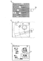
以下、本発明の実施の形態の携帯端末装置について説明する。まず、本発明の実施の形態の携帯端末装置の構成について、図1に示す、本発明の実施の形態の携帯端末装置の構成図を参照して説明する。本発明の実施の形態の携帯端末装置は、表示部11、タッチパッド12、操作キー13、実行プログラム記憶部14、演算情報記憶部15、及び制御部16を含んで構成される。表示部11は、液晶ディスプレイや有機ELディスプレイによって構成され、制御部16から出力される制御信号に基づいて各種情報を表示する。タッチパッド12は、装置利用者が押下した位置を検出する各種方式(例えば、静電容量方式、抵抗膜方式、または赤外線遮光方式など)のセンサによって構成され、そのセンサによって検出した信号を制御部16に出力する。操作キー13は、0〜9までの番号や特定の機能が割り当てられたキーによって構成され、装置利用者から受け付けた入力信号を制御部16に出力する。実行プログラム記憶部14は、制御部16が実行する各種プログラムを記憶する。演算情報記憶部15は、制御部16がプログラムを実行した結果出力されるデータを記憶する。
Hereinafter, a mobile terminal device according to an embodiment of the present invention will be described. First, the configuration of the mobile terminal device according to the embodiment of the present invention will be described with reference to the configuration diagram of the mobile terminal device according to the embodiment of the present invention shown in FIG. The portable terminal device according to the embodiment of the present invention includes a
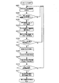
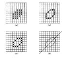
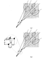
次に、本発明の実施の形態の携帯端末装置による処理の流れと各処理の内容を説明する。図2に、本発明の実施の形態の携帯端末装置が実施するフローチャートを、図3に、本発明の実施の形態の携帯端末装置が実施する長軸の算出処理を説明する図を、図4に、本発明の実施の形態の携帯端末装置が実施する根元位置の特定処理を説明する図を、それぞれ示す。 Next, the flow of processing by the mobile terminal device according to the embodiment of the present invention and the contents of each processing will be described. FIG. 2 is a flowchart executed by the mobile terminal device according to the embodiment of the present invention. FIG. 3 is a diagram explaining the major axis calculation process performed by the mobile terminal device according to the embodiment of the present invention. The figure explaining the specific process of the root position which the portable terminal device of embodiment of this invention implements is shown, respectively.
まず、装置利用者が指の先端をタッチパッド12に接触させてタッチパッド12による操作を行うと、タッチパッド12は、タッチパッド12における押下された位置を示す信号を制御部16に出力する(ステップS201)。例えば、タッチパッド12が静電容量方式である場合、格子状にコンデンサが配置されるタッチパッド12は、押下されていない箇所に配置されているコンデンサからよりも、押下された箇所に配置されているコンデンサからより低い電圧値の信号を出力する。このため、制御部16は、タッチパッド12から出力される信号の電圧値から、タッチパッド12における押下された位置座標(図3(a)では、押下された位置座標は、マトリックスのうちの黒塗りのセルに相当する。これらのセルの集合を以後、押下領域と称する。)を特定することができる。
First, when the user of the apparatus brings the tip of a finger into contact with the
続いて、制御部16は、実行プログラム記憶部14に記憶された接触面積認識プログラムを実行して、押下領域の面積、つまり、押下領域を構成するセルの総数が、所定値よりも大きいか否かを判定する(ステップS202)。制御部16は、押下領域の面積が所定値よりも大きければ(ステップS202、Y)、実行プログラム記憶部14に記憶された長軸算出プログラムを実行して、以降説明する処理を行う。一方、制御部16は、押下領域の面積が所定値よりも小さければ(ステップS202、N)、以降説明する処理を行わずに、タッチパッド12から出力される信号を待ち受ける。
Subsequently, the
制御部16は、押下領域の面積が所定値よりも大きければ、押下領域に対してエッジ抽出処理を実行する(ステップS203)。制御部16は、エッジ抽出処理が施された押下領域の輪郭の位置座標(図3(b)では、押下領域の輪郭の位置座標は、マトリックスのうちの黒塗りのセルに相当する。)を認識する。さらに、制御部16は、エッジ抽出処理により抽出した押下領域の輪郭の位置座標を用いて、楕円近似処理を実行する(ステップS204。図3(c)で示される楕円が、楕円近似処理により算出された楕円に相当する。)。楕円近似処理には、例えば最小二乗法を用いる。制御部16は、こうして算出した楕円方程式の長軸を一部に含む直線(図3(d)で示される直線が相当する。)を算出し、その直線の一次方程式を表すパラメータを演算情報記憶部15に記憶する(ステップS205)。この後、制御部16は、タッチパッド12から信号が入力される度に、上記の処理を行う。
If the area of the pressed area is larger than the predetermined value, the
装置利用者が複数回、指の先端をタッチパッド12に接触させてタッチパッド12による操作を行い、制御部16が所定数の上記パラメータを演算情報記憶部15に記憶させた場合(ステップS206、Y)、制御部16は、実行プログラム記憶部14に記憶された交点算出プログラムを実行して、各直線とその他の直線との交点の位置座標を算出する(ステップS207)。図4(a)は、5個の上記パラメータを記憶した時点で各直線とその他の直線との交点の位置座標を算出する場合であり、その交点を「●」(黒塗り)で示している。
When the apparatus user makes an operation with the
続いて、制御部16は、実行プログラム記憶部14に記憶された根元位置特定プログラムを実行して、算出した複数の交点の位置座標の平均値を算出する(ステップS208)。図4(b)では、交点の位置座標の平均値を「○」(黒抜き)で示している。そして、制御部16は、交点の位置座標それぞれ(図4(b)における「●」)と、交点の位置座標の平均値(図4(b)における「○」)と、の差分を基に、交点の位置座標の平均値に対する交点の位置座標ぞれぞれのばらつきを算出する(ステップS209)。ばらつきの算出手法の一例を図4(b)を参照して説明すると、交点の位置座標それぞれと交点の位置座標の平均値とのX軸方向の差分(図4(b)におけるxa、xb、xc、…)およびY軸方向の差分(図4(b)におけるya、yb、yc、…)から、ばらつきを数値化する2つの数式f(x)=xa2+xb2+xc2+…、g(y)=ya2+yb2+yc2+…を算出する。制御部16は、ばらつきを表す2つの数式f(x)、g(y)の数値それぞれが所定値よりも小さければ(ステップS210、Y)、上記交点の位置座標の平均値にタッチパッド12に接触する指の根元があるとして、上記交点の位置座標の平均値を根元位置として認識する(ステップS211)。
Subsequently, the
本発明の実施の形態の携帯端末装置では、上述した処理を実施してタッチパネル12を操作する指の根元位置を認識する。指の根元位置を算出するに当たって、上述した処理では次の点に着目している。すなわち、一つ目は、タッチパッド操作時における指の接触面が楕円形状である点、二つ目は、タッチパッド操作時に指の根元から離れた箇所に指の先端を接触させる場合、上記楕円形状の長軸の延長線上にその根元が位置する点、三つ目は、タッチパッドにおける上記楕円が位置する箇所が異なっても、携帯端末装置を持ち直さない限り、それらの楕円の長軸が指の根元の位置に集中する点、である。図5に、タッチパネル操作時における指の接触面の特徴を示す。
In the mobile terminal device according to the embodiment of the present invention, the above-described processing is performed to recognize the base position of the finger operating the
図5(a)、図5(b)に示すように、タッチパッド操作時に指の根元から離れた箇所に指の先端を接触させる場合であろうと、指の根元に近い箇所に指の先端を接触させる場合であろうと、タッチパッド12に対する指の接触面51、52は、楕円形状に近いものになる。ところが、指の根元から離れた箇所に指の先端を接触させる場合は、指の根元に近い箇所に指の先端を接触させる場合と比べて、指の接触面51の面積が大きくなる。この特徴を利用して、上述した処理のステップS202では、押下領域の大小によって、押下された箇所が指の根元から離れた箇所であるのか、指の根元に近い箇所であるのかを区別している。なお、押下領域の大小を判別する閾値を、例えば、それまでに算出した押下領域の平均値として設定することができる。
As shown in FIGS. 5A and 5B, when the tip of the finger is brought into contact with a location away from the base of the finger during touch pad operation, the tip of the finger is placed near the base of the finger. Even in the case of contact, the contact surfaces 51 and 52 of the finger with respect to the
また、指の根元から離れた箇所に指の先端を接触させる場合には、楕円形状の長軸の延長線上にその根元が位置することを利用して、比較的面積の大きい押下領域を近似する楕円の長軸から指の根元の方向を特定し、さらに、その長軸と、別の押下領域を近似する楕円の長軸と、の交点から指の根元の位置53を特定する。なお、装置利用者が携帯端末装置を持ち直すことによって指の根元の位置が変わることを考慮して、上述した処理のステップS207では、記憶しておいたパラメータのうちの新しいもの複数個から、交点を算出するようにしてもよい。これにより、装置利用者による携帯端末装置の持ち直しによって指の根元の位置が変わっても、その変化に追従して当該位置を特定することができる。
In addition, when the tip of the finger is brought into contact with a location away from the base of the finger, a pressing area having a relatively large area is approximated by utilizing the fact that the base is located on the extended line of the elliptical long axis. The direction of the base of the finger is specified from the long axis of the ellipse, and further, the
このようにして算出した指の根元の位置を利用して後述する実施例のようなユーザインタフェースを実現することにより、携帯端末装置を片手で保持するとともにその手でタッチパネルやタッチパッドを操作する場合に、その操作性を向上させることができる。以下、タッチパッドを操作する指の根元の位置を利用したユーザインタフェースの一例を説明する。 When the mobile terminal device is held with one hand and the touch panel or touch pad is operated with the hand by realizing the user interface as described in the embodiments described later by using the calculated finger base position in this way Furthermore, the operability can be improved. Hereinafter, an example of a user interface using the base position of the finger operating the touch pad will be described.
実施例1では、本発明の実施の形態の携帯端末装置は、特定した指の根元の位置に応じて、表示部11に表示する表示内容を変化させる。近年の携帯端末装置に搭載されるユーザインタフェースには、機能を視覚的に認識させるとともに、当該機能の実行指示を簡易な操作で受け付けるアイコンやランチャーメニューを利用したものがある。図6に、本発明の実施例1の携帯端末装置による表示例と表示時における根元位置の関係を示す。
In Example 1, the mobile terminal device according to the embodiment of the present invention changes the display content displayed on the
図6に示すように、電話帳、カメラ、メニュー、音楽、メールなどのアイコンやランチャーメニューを、特定した指の根元の位置53から所定の距離離れた位置に表示させる。これにより、装置利用者は、タッチパッド12を操作する指を大きく折り曲げて操作することがなくなるため、快適に操作することができる。
As shown in FIG. 6, icons such as a phone book, camera, menu, music, mail, and launcher menu are displayed at a position that is a predetermined distance away from the
具体的には、まず、本実施例1の携帯端末装置における実行プログラム記憶部14は、各種機能(電話帳、カメラ、音楽、メールなど)のプログラムと、各種機能の実行を指示するアイコンとを対応付けて記憶している。
Specifically, first, the execution
また、各種機能に対応するアイコンは、メニュー表示においてタッチパッドが操作されていないときに表示部11に表示する初期配置情報(例えば、表示部11の左上隅を基点としてX軸方向20ピクセル、Y軸方向100ピクセルなど)と、画像サイズをそれぞれ記憶している。
In addition, icons corresponding to various functions are initial arrangement information to be displayed on the
ここで、制御部16は、表示部11が各種機能に対応する複数のアイコンを初期配置情報に従ってメニュー表示しているときに、タッチパッド12が操作された場合、上述の算出方法を用いて装置利用者の指の根元位置を認識する。
Here, when the
そして、制御部16は、根元位置を中心とした一定の距離範囲と、複数のアイコンの初期配置情報とから前記距離範囲内に含まれるアイコンがあるか否かを判断する。
前記距離範囲内に含まれるアイコンが無い場合、制御部16は初期配置情報に従って複数のアイコンを表示部11に表示する。
Then, the
When there is no icon included in the distance range, the
一方、前記距離範囲内に含まれるアイコンがある場合、制御部16は、根元位置を中心とした一定の距離範囲内にアイコンが含まれないよう表示させる。例えば、初期配置情報から所定の距離離れた位置に全て又は特定のアイコンを移動させて表示させたり、アイコンの画像サイズを縮小する等がある。これにより、タッチパッド12を操作する指を大きく折り曲げて操作することがなくなるため、快適に操作することができる。
On the other hand, when there is an icon included in the distance range, the
また、特定した指の根元の位置53の近辺に、操作する必要のない画面(例えば、テレビ放送を受信可能な携帯端末装置であればテレビ放送画面、または、オーディオデータを再生可能な携帯端末装置であれば再生中のオーディオデータの楽曲情報、など)を表示するようにしてもよい。 Further, a screen that does not need to be operated in the vicinity of the specified finger base position 53 (for example, a mobile terminal device that can receive a television broadcast, a television broadcast screen or a mobile terminal device that can reproduce audio data). If so, the music information of the audio data being reproduced may be displayed.
具体的には、まず、本実施例1の携帯端末装置における実行プログラム記憶部14は、操作する必要の無い画面(以下、操作不要画面)を含む各種機能(テレビ放送、オーディオなど)のプログラムを記憶している。そして各種機能の操作不要画面表示において、タッチパッドが操作されていないときに表示部11に表示する初期配置情報(例えば、表示部11の左上隅を基点としてX軸方向20ピクセル、Y軸方向100ピクセルなど)と、画像サイズをそれぞれ記憶している。
Specifically, first, the execution
ここで、制御部16は、表示部11が各種機能を表示しているときにタッチパッド12が操作された場合、上述の算出方法を用いて装置利用者の指の根元位置を認識する。
Here, when the
そして、制御部16は、根元位置を中心とした一定の距離範囲と、操作不要画面の初期配置情報とから前記距離範囲外に表示される操作不要画面があるか否かを判断する。
Then, the
前記距離範囲外の操作不要画面がない場合、制御部16は初期配置情報に従って操作不要画面を表示部11に表示する。
When there is no operation unnecessary screen outside the distance range, the
一方、前記距離範囲外に操作不要画面がある場合、制御部16は、根元位置を中心とした一定の距離範囲内に操作不要画面が含まれるよう表示させる。例えば、指の根元位置に、最も近い表示部端部に沿うようにテレビ放送画面を表示する等がある。これにより、タッチパッド12を操作する指を大きく折り曲げて操作することがなくなるため、快適に操作することができる。
On the other hand, when there is an operation unnecessary screen outside the distance range, the
また、装置利用者が操作ミスした場合に同利用者に不利益になる操作(例えば、データを削除する操作、個人情報の入力決定操作、実行中の処理を中止する操作)のために表示する表示対象を指の根元の位置53付近に表示させることにより、敢えて窮屈な姿勢での操作を装置利用者に強いることで操作ミスの発生を抑えることもできる。
In addition, it is displayed for an operation (for example, an operation for deleting data, an operation for determining input of personal information, or an operation for canceling a process being executed) that is disadvantageous to the user when the user makes an operation mistake. By displaying the display target in the vicinity of the
具体的には、まず、本実施例1の携帯端末装置における実行プログラム記憶部14は、各種機能(電話帳、カメラ、音楽、メールなど)のプログラムを記憶している。
また、各種機能におけるデータ削除操作、実行中止操作などの操作ミスを避けたい操作(以下、ミス防止対象)は、各種機能実行時においてタッチパッドが操作されていないときに表示部11に表示する初期配置情報(例えば、表示部11の左上隅を基点としてX軸方向20ピクセル、Y軸方向100ピクセルなど)と、画像サイズをそれぞれ記憶している。
Specifically, first, the execution
In addition, operations that are desired to avoid operation mistakes such as data deletion operations and execution stop operations in various functions (hereinafter, error prevention targets) are initially displayed on the
ここで、制御部16は、表示部11が各種機能を表示しているときにタッチパッド12が操作された場合、上述の算出方法を用いて装置利用者の指の根元位置を認識する。
そして、制御部16は、根元位置を中心とした一定の距離範囲と、ミス防止対象の初期配置情報とから前記距離範囲外に表示されるミス防止対象があるか否かを判断する。
Here, when the
Then, the
前記距離範囲外のミス防止対象がない場合、制御部16は初期配置情報に従って操作不要画面を表示部11に表示する。
一方、前記距離範囲外にミス防止対象がある場合、制御部16は、根元位置を中心とした一定の距離範囲内にミス防止対象が含まれるよう表示させる。例えば、指の根元位置に、最も近い表示部端部に沿うように中止アイコンを表示する等がある。これにより、タッチパッド12を操作する指を大きく折り曲げ意識的にタッチしなければ操作しにくくなり、操作ミスを低減することができる。
When there is no mistake prevention target outside the distance range, the
On the other hand, when there is a mistake prevention target outside the distance range, the
実施例1では、特定した指の根元の位置53に対応する表示部の表示箇所には、操作対象を表示させないことにより、タッチパッドによる操作性を向上させるものであった。実施例2では、特定した指の根元の位置53に対応する表示部の表示箇所に操作対象を表示させつつ、タッチパッドによる操作性を向上させる構成について説明する。図7に、本発明の実施例2の携帯端末装置による表示例と表示時における根元位置の関係を示す。
In the first embodiment, the operability by the touch pad is improved by not displaying the operation target at the display portion of the display unit corresponding to the specified
ディスプレイ上に表示された対象を指定するポインタには、ある位置座標(点)を含む対象を指定するもの(位置指定ポインタと称する)と、ある位置座標の集合(範囲)を一部に含む対象を指定するもの(範囲指定ポインタと称する)がある。実施例2では、図7の中段に示すように、特定した指の根元の位置53からの距離に応じて、位置指定ポインタ71(矢印の先端の位置座標含む対象を指定する。)と範囲指定ポインタ72(丸で囲まれる位置座標の一部を含む対象を指定する。)との切り替え表示、及び範囲指定ポインタの範囲の切り替え表示、を行うものである。具体的には、制御部16は、実行プログラム記憶部14に記憶されたポインタ表示プログラムを実行して、タッチパッド12から入力する位置座標と、特定した指の根元の位置53と、の距離を比較し、その距離がある閾値よりも長ければ、タッチパッド12から入力する位置座標を矢印の先端とする位置指定ポインタ71を表示部11に表示させ、その距離がある閾値よりも短ければ、タッチパッド12から入力する位置座標を中心とし、その距離が短いほど長くなる半径の範囲指定ポインタ72を表示部11に表示させる。
Pointers that specify the target displayed on the display include those that specify a target including a certain position coordinate (point) (referred to as a position specification pointer), and targets that partially include a set (range) of a certain position coordinate. Is designated (referred to as a range designation pointer). In the second embodiment, as shown in the middle part of FIG. 7, a position designation pointer 71 (designates an object including the position coordinates of the tip of the arrow) and range designation according to the distance from the identified
図7の下段は、上記範囲指定ポインタ72によって複数の対象(「・居酒屋」と「・レストラン」)を指定した場合の表示例である。制御部16は、範囲指定ポインタ72によって複数の対象が指定された後、対象(「・居酒屋」と「・レストラン」)を別のウィンドウ73に表示させ、操作キー13によるキー入力を受け付けてそのキー入力に応じた対象を選択する。操作キー13によるキー入力を受け付けない場合には、再度、範囲指定ポインタ72によって対象が指定された後、その対象を別のウィンドウ73に表示させる。
The lower part of FIG. 7 is a display example when a plurality of objects (“Izakaya” and “• Restaurant”) are designated by the
以上のように、タッチパッド12から入力する位置座標と、特定した指の根元の位置53との距離に応じて、位置指定ポインタ71と範囲指定ポインタ72との切り替え表示、及び範囲指定ポインタの範囲の切り替え表示を行うことにより、指の根元に近い箇所に指の先端を接触させる場合には、ポインタが指定する範囲を拡大させ、表示部に表示された対象を指定し易い操作環境を提供することができる。
As described above, according to the distance between the position coordinates input from the
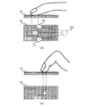
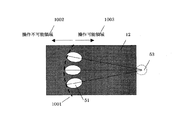
タッチパッドを備える携帯端末装置のサイズや形状などによっては、指を完全に伸ばしても届かない領域以外に操作を要するアイコンを配置すれば、十分操作性の高い携帯端末装置を提供することができる場合がある。例えば、親指による操作が想定された、表示面と透過型のタッチパッドとが同一面上に重なって配置されている携帯端末装置が挙げられる。本実施例では、指を完全に伸ばしても届かない領域に操作を要するアイコンを配置せず、指を伸縮すれば届く領域にのみ操作を要するアイコンを配置させる携帯端末装置を例示する。以下、図10および図11を参照しながら本実施例を説明する。 Depending on the size and shape of the mobile terminal device including the touch pad, a mobile terminal device with sufficiently high operability can be provided by placing an icon that requires an operation other than an area that cannot be reached even when the finger is fully extended. There is a case. For example, there is a portable terminal device in which a display surface and a transmissive touch pad are arranged on the same surface and assumed to be operated with a thumb. In the present embodiment, a mobile terminal device in which an icon that requires an operation is not arranged in an area that cannot be reached even when the finger is completely extended, and an icon that requires an operation is arranged only in an area that can be reached when the finger is extended or contracted. Hereinafter, this embodiment will be described with reference to FIGS. 10 and 11.
図10に示すように、ユーザは、親指の根元を位置53に配置しながら、親指の先を連続的に移動させて、タッチパッドを押下して複数の接触面51を形成する。タッチパッド12は、複数の接触面51のそれぞれの位置を検出する。検出する接触面51のそれぞれの位置は、接触面51の先端、中央、または末端など、適宜決定すればよい。制御部16(図1参照)は、連続的に移動した複数の接触面51のそれぞれを、最短距離で結ぶ曲線又は直線を、操作可能領域の限界1001として決定する。さらに制御部16は、操作可能領域の限界1001に対して親指の根元の位置53に近い領域を操作可能領域1003と決定し、逆側、すなわち、操作可能領域の限界1001に対して親指の根元の位置53に遠い領域を操作不可能領域1002と決定する。
As shown in FIG. 10, the user moves the tip of the thumb continuously while placing the base of the thumb at the
上記の説明では、ユーザが複数の接触面51を形成する場合を説明したが、複数の接触面51を形成する必要は無く、少なくとも1つの接触面51があれば、上記と同様に、操作可能領域の限界1001、操作可能領域1003、および操作不可能領域1002を決定することができる。具体的には、タッチパッド12は、1つの接触面51の位置を検出する。制御部16は、1つの接触面51の位置に基づいて、親指の根元位置53を中心とした円弧状の操作可能領域の限界1001を決定する。さらに制御部16は、上記と同様に、操作可能領域の限界1001に対して親指の根元の位置53に近い領域を操作可能領域1003と決定し、逆側、すなわち、操作可能領域の限界1001に対して親指の根元の位置53に遠い領域を操作不可能領域1002と決定する。
In the above description, the case where the user forms a plurality of contact surfaces 51 has been described. However, it is not necessary to form the plurality of contact surfaces 51. If there is at least one
表示部11は、例えば、当初図11(a)に示すように表示部11(タッチパッド12)全面にマトリクス状に配置された複数のアイコン1004を表示させていたとする。制御部16は、操作可能領域1003の中にのみアイコン1004が配置されるよう、アイコン1004を移動させる。表示部11は、制御部16からの指示にしたがって、図11(b)に示すように操作可能領域1003にのみアイコン1004が配置されるように表示する。すなわち、表示部12は、操作可能領域の限界1001を表示限界として、この表示限界の内側のみにアイコン1004が配置されるように表示する。制御部16からの指示にしたがって表示部11がアイコン1004の表示を行うタイミングは、ユーザからの指示によるものでもよいし、制御部16からの指示によるものでもよい。本実施例では、操作可能なアイコン1004の数は減少するが、指で操作可能な領域にのみにアイコンを表示するので、十分操作性の高い携帯端末装置を提供することができる。
For example, the
なお、本発明の実施の形態では、タッチパッドを備える携帯端末装置について説明したが、タッチパネルを備える携帯端末装置であっても、同様の効果を得ることができる。 In the embodiment of the present invention, the portable terminal device including the touch pad has been described. However, even if the portable terminal device includes the touch panel, the same effect can be obtained.
本発明の携帯端末装置及び表示制御方法によれば、携帯端末装置を片手で保持するとともにその手でタッチパネルやタッチパッドを操作する場合に、その操作性を向上させることができるという効果を奏し、タッチパネルやタッチパッドを備えた携帯端末装置に関する分野において有用である。 According to the portable terminal device and the display control method of the present invention, when the portable terminal device is held with one hand and the touch panel or touch pad is operated with the hand, the operability can be improved. This is useful in the field related to a mobile terminal device having a touch panel and a touch pad.
11 表示部
12 タッチパッド
13 操作キー
14 実行プログラム記憶部
15 演算情報記憶部
16 制御部
51、52 接触面
53 指の根元の位置
71 位置指定ポインタ
72 範囲指定ポインタ
73 ウィンドウ
81 表示部
82 タッチパッド
83 人差し指
1001 操作可能領域の限界
1002 操作不可能領域
1003 操作可能領域
1004 アイコン
DESCRIPTION OF
Claims (8)
押下を検出する押下検出部と、
前記押下検出部によって押下を検出した押下領域に基づいて、前記表示部上での表示位置が固定的に設定されている表示対象の表示位置を制御する制御部と、
を備える携帯端末装置。 A display unit for displaying various information;
A pressing detection unit for detecting pressing;
A control unit that controls a display position of a display target in which a display position on the display unit is fixedly set based on a pressing area in which pressing is detected by the pressing detection unit;
A mobile terminal device comprising:
前記制御部は、
前記押下検出部によって押下を検出した押下領域の少なくとも一点を通り、当該押下領域の長手方向を傾きとする直線を算出する直線算出部と、
前記直線算出部によって前記押下領域毎に算出される複数の直線が交差する交点が所定の範囲内に含まれる場合、前記交点を平均した平均位置を算出する位置算出部と、
前記平均位置に基づいて、前記表示対象の表示位置を制御する表示制御手段と、
を備える携帯端末装置。 The mobile terminal device according to claim 1,
The controller is
A straight line calculating unit that calculates a straight line that passes through at least one point of the pressed area where the pressed detection is detected by the pressed detection unit and has an inclination in the longitudinal direction of the pressed area;
A position calculation unit that calculates an average position obtained by averaging the intersections when an intersection at which a plurality of straight lines calculated for each pressed area by the straight line calculation unit intersect is included in a predetermined range;
Display control means for controlling the display position of the display object based on the average position;
A mobile terminal device comprising:
前記直線算出部は、楕円として近似される前記押下領域の長軸を、前記直線として算出する、
携帯端末装置。 The mobile terminal device according to claim 2,
The straight line calculation unit calculates the long axis of the pressed area approximated as an ellipse as the straight line;
Mobile terminal device.
前記表示制御部は、前記平均位置に基づいて、前記表示部に表示させる前記表示対象としての画像の表示位置を制御する、
携帯端末装置。 The mobile terminal device according to claim 3,
The display control unit controls a display position of an image as the display target to be displayed on the display unit based on the average position.
Mobile terminal device.
前記表示制御部は、前記平均位置に基づいて、前記表示部に表示されたポインタによって指し示す範囲を制御する、
携帯端末装置。 The mobile terminal device according to claim 3,
The display control unit controls a range indicated by a pointer displayed on the display unit based on the average position;
Mobile terminal device.
前記制御部は、前記連続的に移動する押下点のそれぞれの位置を結ぶ直線または曲線を表示限界とする表示限界決定部と、前記表示限界の内側のみに前記表示対象が表示されるように前記表示対象を移動させる表示制御部と、を有し、
前記表示部は、前記表示限界の内側のみに前記表示対象を表示する、
請求項1に記載の携帯端末装置。 The pressing detection unit detects the position of each pressing point that moves continuously,
The control unit includes a display limit determining unit that displays a straight line or a curve connecting the positions of the continuously moving pressing points, and the display target is displayed only inside the display limit. A display control unit for moving a display target,
The display unit displays the display object only inside the display limit.
The mobile terminal device according to claim 1.
前記制御部は、前記押下検出部によって検出された少なくとも1つの押下点の位置に基づいて円弧状の表示限界を決定する表示限界決定部と、前記表示限界の内側のみに前記表示対象が表示されるように前記表示対象を移動させる表示制御部と、を有し、
前記表示部は、前記表示限界の内側のみに前記表示対象を表示する請求項1に記載の携帯端末装置。 The pressing detection unit detects a position of at least one pressing point,
The control unit displays a display limit determining unit that determines an arc-shaped display limit based on a position of at least one pressing point detected by the pressing detection unit, and the display target is displayed only inside the display limit. A display control unit that moves the display object so that,
The portable terminal device according to claim 1, wherein the display unit displays the display target only inside the display limit.
押下を検出した押下領域に基づいて、表示位置が固定的に設定されている表示対象の表示位置を制御し、
表示位置が制御された前記表示対象を表示する、
表示制御方法。 Detect the pressed area,
Based on the pressed area where the press is detected, the display position of the display object whose display position is fixedly set is controlled,
Displaying the display object whose display position is controlled,
Display control method.
Priority Applications (1)
| Application Number | Priority Date | Filing Date | Title |
|---|---|---|---|
| JP2008009172A JP4979600B2 (en) | 2007-09-05 | 2008-01-18 | Portable terminal device and display control method |
Applications Claiming Priority (3)
| Application Number | Priority Date | Filing Date | Title |
|---|---|---|---|
| JP2009531052 | 2007-09-05 | ||
| JP2009531052A JPWO2009031214A1 (en) | 2007-09-05 | 2007-09-05 | Portable terminal device and display control method |
| JP2008009172A JP4979600B2 (en) | 2007-09-05 | 2008-01-18 | Portable terminal device and display control method |
Related Child Applications (1)
| Application Number | Title | Priority Date | Filing Date |
|---|---|---|---|
| JP2012046623A Division JP2012113745A (en) | 2007-09-05 | 2012-03-02 | Mobile terminal device and display control method |
Publications (2)
| Publication Number | Publication Date |
|---|---|
| JP2010146032A true JP2010146032A (en) | 2010-07-01 |
| JP4979600B2 JP4979600B2 (en) | 2012-07-18 |
Family
ID=42566460
Family Applications (2)
| Application Number | Title | Priority Date | Filing Date |
|---|---|---|---|
| JP2008009172A Expired - Fee Related JP4979600B2 (en) | 2007-09-05 | 2008-01-18 | Portable terminal device and display control method |
| JP2012046623A Withdrawn JP2012113745A (en) | 2007-09-05 | 2012-03-02 | Mobile terminal device and display control method |
Family Applications After (1)
| Application Number | Title | Priority Date | Filing Date |
|---|---|---|---|
| JP2012046623A Withdrawn JP2012113745A (en) | 2007-09-05 | 2012-03-02 | Mobile terminal device and display control method |
Country Status (1)
| Country | Link |
|---|---|
| JP (2) | JP4979600B2 (en) |
Cited By (10)
| Publication number | Priority date | Publication date | Assignee | Title |
|---|---|---|---|---|
| WO2013031661A1 (en) * | 2011-08-29 | 2013-03-07 | シャープ株式会社 | Detection apparatus, detection method, and detection program |
| WO2013150998A1 (en) | 2012-04-05 | 2013-10-10 | シャープ株式会社 | Mobile electronic device |
| JP2013229002A (en) * | 2012-03-30 | 2013-11-07 | Ntt Docomo Inc | Information terminal, input object display method, and input object display program |
| JP2013229004A (en) * | 2012-03-27 | 2013-11-07 | Ntt Docomo Inc | Portable terminal, terminal display method and terminal display program |
| JP2014021827A (en) * | 2012-07-20 | 2014-02-03 | Nec Casio Mobile Communications Ltd | Information appliance, method and program for display control |
| JP2014238755A (en) * | 2013-06-10 | 2014-12-18 | レノボ・シンガポール・プライベート・リミテッド | Input system, input method, and smartphone |
| JP2015099436A (en) * | 2013-11-18 | 2015-05-28 | 三菱電機株式会社 | Interface device |
| JP2016106307A (en) * | 2016-01-20 | 2016-06-16 | コニカミノルタ株式会社 | Image forming apparatus, control method for image forming apparatus, and control program for image forming apparatus |
| US9846537B2 (en) | 2014-06-20 | 2017-12-19 | International Business Machines Corporation | Touch panel input item correction in accordance with angle of deviation |
| US9983700B2 (en) | 2011-07-14 | 2018-05-29 | Nec Corporation | Input device, image display method, and program for reliable designation of icons |
Families Citing this family (10)
| Publication number | Priority date | Publication date | Assignee | Title |
|---|---|---|---|---|
| KR101341737B1 (en) * | 2012-06-21 | 2013-12-16 | 주식회사 팬택 | Apparatus and method for controlling terminal using touch the back of the terminal |
| JP6137453B2 (en) | 2013-02-08 | 2017-05-31 | インターナショナル・ビジネス・マシーンズ・コーポレーションInternational Business Machines Corporation | Control device and control program |
| JP6218415B2 (en) | 2013-04-02 | 2017-10-25 | キヤノン株式会社 | Information processing apparatus, control method, and computer program |
| JP6331022B2 (en) * | 2013-09-27 | 2018-05-30 | パナソニックIpマネジメント株式会社 | Display device, display control method, and display control program |
| JP2015133021A (en) * | 2014-01-14 | 2015-07-23 | シャープ株式会社 | Terminal, and terminal control method |
| CN103885632B (en) * | 2014-02-22 | 2018-07-06 | 小米科技有限责任公司 | Input method and device |
| JP6344355B2 (en) * | 2015-09-28 | 2018-06-20 | キヤノンマーケティングジャパン株式会社 | Electronic terminal, and control method and program thereof |
| JP7222663B2 (en) * | 2018-11-05 | 2023-02-15 | 株式会社コーエーテクモゲームス | Program, information processing method, and information processing apparatus |
| JP7129352B2 (en) * | 2019-01-30 | 2022-09-01 | シャープ株式会社 | Operation range setting device, game device, operation range setting method, and program |
| JP7272832B2 (en) * | 2019-03-14 | 2023-05-12 | Fcnt株式会社 | Information processing device and program |
Citations (8)
| Publication number | Priority date | Publication date | Assignee | Title |
|---|---|---|---|---|
| JPH10232735A (en) * | 1997-02-18 | 1998-09-02 | Sharp Corp | Input device for information equipment |
| JP2002164980A (en) * | 2000-11-29 | 2002-06-07 | Kyocera Corp | Mobile terminal |
| JP2005234993A (en) * | 2004-02-20 | 2005-09-02 | Toshiba Corp | Image display device and image display method |
| JP2007052795A (en) * | 2006-08-21 | 2007-03-01 | Fujifilm Holdings Corp | Operation device of apparatus provided with screen display part, and digital camera |
| JP2007179502A (en) * | 2005-12-28 | 2007-07-12 | Sharp Corp | Information processing device |
| JP2008003671A (en) * | 2006-06-20 | 2008-01-10 | Sharp Corp | Electronic device and method of operating electronic device |
| JP2009158989A (en) * | 2006-04-06 | 2009-07-16 | Nikon Corp | camera |
| JP2009163278A (en) * | 2007-12-21 | 2009-07-23 | Toshiba Corp | Portable equipment |
-
2008
- 2008-01-18 JP JP2008009172A patent/JP4979600B2/en not_active Expired - Fee Related
-
2012
- 2012-03-02 JP JP2012046623A patent/JP2012113745A/en not_active Withdrawn
Patent Citations (8)
| Publication number | Priority date | Publication date | Assignee | Title |
|---|---|---|---|---|
| JPH10232735A (en) * | 1997-02-18 | 1998-09-02 | Sharp Corp | Input device for information equipment |
| JP2002164980A (en) * | 2000-11-29 | 2002-06-07 | Kyocera Corp | Mobile terminal |
| JP2005234993A (en) * | 2004-02-20 | 2005-09-02 | Toshiba Corp | Image display device and image display method |
| JP2007179502A (en) * | 2005-12-28 | 2007-07-12 | Sharp Corp | Information processing device |
| JP2009158989A (en) * | 2006-04-06 | 2009-07-16 | Nikon Corp | camera |
| JP2008003671A (en) * | 2006-06-20 | 2008-01-10 | Sharp Corp | Electronic device and method of operating electronic device |
| JP2007052795A (en) * | 2006-08-21 | 2007-03-01 | Fujifilm Holdings Corp | Operation device of apparatus provided with screen display part, and digital camera |
| JP2009163278A (en) * | 2007-12-21 | 2009-07-23 | Toshiba Corp | Portable equipment |
Cited By (15)
| Publication number | Priority date | Publication date | Assignee | Title |
|---|---|---|---|---|
| US9983700B2 (en) | 2011-07-14 | 2018-05-29 | Nec Corporation | Input device, image display method, and program for reliable designation of icons |
| WO2013031661A1 (en) * | 2011-08-29 | 2013-03-07 | シャープ株式会社 | Detection apparatus, detection method, and detection program |
| JP2013229004A (en) * | 2012-03-27 | 2013-11-07 | Ntt Docomo Inc | Portable terminal, terminal display method and terminal display program |
| JP2013229002A (en) * | 2012-03-30 | 2013-11-07 | Ntt Docomo Inc | Information terminal, input object display method, and input object display program |
| WO2013150998A1 (en) | 2012-04-05 | 2013-10-10 | シャープ株式会社 | Mobile electronic device |
| JP2014021827A (en) * | 2012-07-20 | 2014-02-03 | Nec Casio Mobile Communications Ltd | Information appliance, method and program for display control |
| JP2014238755A (en) * | 2013-06-10 | 2014-12-18 | レノボ・シンガポール・プライベート・リミテッド | Input system, input method, and smartphone |
| US10387033B2 (en) | 2013-06-10 | 2019-08-20 | Lenovo (Singapore) Pte. Ltd. | Size reduction and utilization of software keyboards |
| JP2015099436A (en) * | 2013-11-18 | 2015-05-28 | 三菱電機株式会社 | Interface device |
| US9851847B2 (en) | 2014-06-20 | 2017-12-26 | International Business Machines Corporation | Touch panel input item correction in accordance with angle of deviation |
| US9846537B2 (en) | 2014-06-20 | 2017-12-19 | International Business Machines Corporation | Touch panel input item correction in accordance with angle of deviation |
| US10216334B2 (en) | 2014-06-20 | 2019-02-26 | International Business Machines Corporation | Touch panel input item correction in accordance with angle of deviation |
| US10394382B2 (en) | 2014-06-20 | 2019-08-27 | International Business Machines Corporation | Touch panel input item correction in accordance with angle of deviaton |
| US11023076B2 (en) | 2014-06-20 | 2021-06-01 | International Business Machines Corporation | Touch panel input item correction in accordance with angle of deviation |
| JP2016106307A (en) * | 2016-01-20 | 2016-06-16 | コニカミノルタ株式会社 | Image forming apparatus, control method for image forming apparatus, and control program for image forming apparatus |
Also Published As
| Publication number | Publication date |
|---|---|
| JP2012113745A (en) | 2012-06-14 |
| JP4979600B2 (en) | 2012-07-18 |
Similar Documents
| Publication | Publication Date | Title |
|---|---|---|
| JP4979600B2 (en) | Portable terminal device and display control method | |
| JPWO2009031214A1 (en) | Portable terminal device and display control method | |
| US9060068B2 (en) | Apparatus and method for controlling mobile terminal user interface execution | |
| JP5507494B2 (en) | Portable electronic device with touch screen and control method | |
| KR101597844B1 (en) | Interpreting ambiguous inputs on a touch-screen | |
| US9626104B2 (en) | Thumb access area for one-handed touchscreen use | |
| US8466934B2 (en) | Touchscreen interface | |
| US9524097B2 (en) | Touchscreen gestures for selecting a graphical object | |
| JP5422724B1 (en) | Electronic apparatus and drawing method | |
| US20110060986A1 (en) | Method for Controlling the Display of a Touch Screen, User Interface of the Touch Screen, and an Electronic Device using The Same | |
| US9459704B2 (en) | Method and apparatus for providing one-handed user interface in mobile device having touch screen | |
| US8456433B2 (en) | Signal processing apparatus, signal processing method and selection method of user interface icon for multi-touch panel | |
| US20130063385A1 (en) | Portable information terminal and method for controlling same | |
| US20130100061A1 (en) | Mobile terminal and controlling method thereof | |
| US9864514B2 (en) | Method and electronic device for displaying virtual keypad | |
| JP6183820B2 (en) | Terminal and terminal control method | |
| JP2011134273A (en) | Information processor, information processing method, and program | |
| WO2016183912A1 (en) | Menu layout arrangement method and apparatus | |
| JP2014016743A (en) | Information processing device, information processing device control method and information processing device control program | |
| JP2014197164A (en) | Display device, display method and display program | |
| JP5820414B2 (en) | Information processing apparatus and information processing method | |
| JP6584876B2 (en) | Information processing apparatus, information processing program, and information processing method | |
| CN103729104A (en) | Electronic apparatus provided with resistive film type touch panel | |
| WO2013080425A1 (en) | Input device, information terminal, input control method and input control program | |
| US11893229B2 (en) | Portable electronic device and one-hand touch operation method thereof |
Legal Events
| Date | Code | Title | Description |
|---|---|---|---|
| A621 | Written request for application examination |
Free format text: JAPANESE INTERMEDIATE CODE: A621 Effective date: 20101111 |
|
| A977 | Report on retrieval |
Free format text: JAPANESE INTERMEDIATE CODE: A971007 Effective date: 20111109 |
|
| A131 | Notification of reasons for refusal |
Free format text: JAPANESE INTERMEDIATE CODE: A131 Effective date: 20120104 |
|
| A521 | Request for written amendment filed |
Free format text: JAPANESE INTERMEDIATE CODE: A523 Effective date: 20120302 |
|
| TRDD | Decision of grant or rejection written | ||
| A01 | Written decision to grant a patent or to grant a registration (utility model) |
Free format text: JAPANESE INTERMEDIATE CODE: A01 Effective date: 20120321 |
|
| A01 | Written decision to grant a patent or to grant a registration (utility model) |
Free format text: JAPANESE INTERMEDIATE CODE: A01 |
|
| A61 | First payment of annual fees (during grant procedure) |
Free format text: JAPANESE INTERMEDIATE CODE: A61 Effective date: 20120417 |
|
| FPAY | Renewal fee payment (event date is renewal date of database) |
Free format text: PAYMENT UNTIL: 20150427 Year of fee payment: 3 |
|
| R150 | Certificate of patent or registration of utility model |
Free format text: JAPANESE INTERMEDIATE CODE: R150 |
|
| LAPS | Cancellation because of no payment of annual fees |