JP2010144549A - Evaporated fuel treatment device - Google Patents
Evaporated fuel treatment device Download PDFInfo
- Publication number
- JP2010144549A JP2010144549A JP2008320537A JP2008320537A JP2010144549A JP 2010144549 A JP2010144549 A JP 2010144549A JP 2008320537 A JP2008320537 A JP 2008320537A JP 2008320537 A JP2008320537 A JP 2008320537A JP 2010144549 A JP2010144549 A JP 2010144549A
- Authority
- JP
- Japan
- Prior art keywords
- casing
- evaporative fuel
- adsorbent
- cylindrical body
- inner casing
- Prior art date
- Legal status (The legal status is an assumption and is not a legal conclusion. Google has not performed a legal analysis and makes no representation as to the accuracy of the status listed.)
- Pending
Links
- 239000000446 fuel Substances 0.000 title claims abstract description 66
- 239000003463 adsorbent Substances 0.000 claims abstract description 99
- 238000002955 isolation Methods 0.000 claims description 20
- 238000012545 processing Methods 0.000 claims description 19
- 238000011144 upstream manufacturing Methods 0.000 claims description 6
- 230000002093 peripheral effect Effects 0.000 claims description 3
- 238000001704 evaporation Methods 0.000 claims 2
- 238000010926 purge Methods 0.000 abstract description 39
- OKTJSMMVPCPJKN-UHFFFAOYSA-N Carbon Chemical compound [C] OKTJSMMVPCPJKN-UHFFFAOYSA-N 0.000 description 12
- JOYRKODLDBILNP-UHFFFAOYSA-N Ethyl urethane Chemical compound CCOC(N)=O JOYRKODLDBILNP-UHFFFAOYSA-N 0.000 description 7
- 238000004891 communication Methods 0.000 description 6
- 239000000463 material Substances 0.000 description 6
- 239000002828 fuel tank Substances 0.000 description 5
- 239000011347 resin Substances 0.000 description 5
- 229920005989 resin Polymers 0.000 description 5
- 230000006835 compression Effects 0.000 description 3
- 238000007906 compression Methods 0.000 description 3
- 238000009792 diffusion process Methods 0.000 description 3
- 230000000694 effects Effects 0.000 description 3
- 230000006872 improvement Effects 0.000 description 3
- 230000004048 modification Effects 0.000 description 3
- 238000012986 modification Methods 0.000 description 3
- 239000004745 nonwoven fabric Substances 0.000 description 3
- 230000035699 permeability Effects 0.000 description 3
- 238000003795 desorption Methods 0.000 description 2
- 238000005187 foaming Methods 0.000 description 2
- 239000013013 elastic material Substances 0.000 description 1
- 239000003502 gasoline Substances 0.000 description 1
- 238000000034 method Methods 0.000 description 1
- 230000005012 migration Effects 0.000 description 1
- 238000013508 migration Methods 0.000 description 1
- 238000005192 partition Methods 0.000 description 1
- 229920006122 polyamide resin Polymers 0.000 description 1
- 238000001179 sorption measurement Methods 0.000 description 1
- 238000009423 ventilation Methods 0.000 description 1
- 238000003466 welding Methods 0.000 description 1
Images

Landscapes
- Supplying Secondary Fuel Or The Like To Fuel, Air Or Fuel-Air Mixtures (AREA)
Abstract
Description
本発明は、自動車の燃料タンクから蒸発した燃料を吸着して、その燃料をエンジン稼働時に燃焼させる蒸発燃料処理装置に関するものである。 The present invention relates to an evaporated fuel processing apparatus that adsorbs fuel evaporated from a fuel tank of an automobile and burns the fuel when the engine is operating.
周知のように、ガソリンを燃料とする自動車では、燃料タンク内の蒸発燃料が大気に放出されることを抑制するために蒸発燃料処理装置(キャニスタ)が用いられている。この蒸発燃料処理装置は、停車時等に燃料タンクから発生する蒸発燃料を吸着材である活性炭に吸着(チャージまたは担持)させ、エンジン稼働時に蒸発燃料処理装置を通して吸気を行うことにより、大気ポートから導入した大気によって同装置内をパージし、吸着した蒸発燃料を脱離させてエンジン内で燃焼させる仕組みとなっている。このパージによる蒸発燃料の脱離によって活性炭の性能が復活して蒸発燃料を良好に且つ繰り返し吸着することが可能となる。 As is well known, an evaporative fuel processing device (canister) is used in an automobile using gasoline as fuel in order to suppress the evaporative fuel in the fuel tank from being released into the atmosphere. This evaporative fuel treatment device adsorbs (charges or carries) the evaporative fuel generated from the fuel tank when the vehicle is stopped, etc., to the activated carbon as an adsorbent, and performs intake air through the evaporative fuel treatment device when the engine is operating, thereby The inside of the apparatus is purged by the introduced atmosphere, and the adsorbed evaporated fuel is desorbed and burned in the engine. The performance of the activated carbon is restored by the desorption of the evaporated fuel by the purge, and the evaporated fuel can be favorably and repeatedly adsorbed.
そして、蒸発燃料処理装置のケーシング内での通流長さを可及的に大きく確保する技術として、特許文献1に記載のように、上記ケーシング内において流路の通流方向に延在する吸着材カートリッジを有底筒状の案内部材で隔離し、その案内部材の内面と吸着材カートリッジの間の空間をガスの流通路として機能させるようにしたものが本出願人により提案されている。
例えばハイブリッドエンジン搭載車に適用される蒸発燃料処理装置にあっては、その特性としてパージ流量が減少する傾向にある一方、特許文献1の図7〜図10に記載されているように、少なくとも吸着材カートリッジとともに案内部材が延在する区間において、角筒状のケーシングと円筒状の案内部材との組み合わせとした場合には、デッドスペースの発生が不可避であり、パージ効率が一段と低下することが判明した。 For example, in an evaporative fuel processing apparatus applied to a hybrid engine-equipped vehicle, the purge flow rate tends to decrease as a characteristic thereof, but as described in FIGS. In the section where the guide member extends along with the material cartridge, when a combination of a square cylindrical casing and a cylindrical guide member is used, it is inevitable that dead space is generated, and the purge efficiency is further reduced. did.
これは、吸着材カートリッジを隔離している案内部材が円筒状のものであるのに対して、その外側のケーシングが角筒状のものであると、両者が同心状ではあっても、案内部材とケーシングとのなす空間のうちケーシングの内隅部(角隅部)に相当する部分ではどうしてもガスが通流しにくいデッドスペースとなり、パージ時においてケーシング周方向でのガスの流通が不均一となることで、パージ流量が少なくなるものと推測される。 This is because the guide member that separates the adsorbent cartridge is cylindrical, whereas the outer casing is a rectangular tube, even if both are concentric, the guide member In the space between the casing and the casing, the portion corresponding to the inner corner (corner corner) of the casing is inevitably a dead space through which gas does not flow, and the gas flow in the casing circumferential direction becomes non-uniform during purging. Therefore, it is estimated that the purge flow rate is reduced.
本発明はこのような課題に着目してなされたものであり、特にパージ効率の向上を図った蒸発燃料処理装置を提供することを目的とする。 The present invention has been made paying attention to such a problem, and an object of the present invention is to provide an evaporative fuel processing apparatus in which purging efficiency is improved.
請求項1に記載の発明は、内部に流路を形成するケーシングの一端に、蒸発燃料が導入される蒸発燃料導入部および蒸発燃料が排出される蒸発燃料排出部がそれぞれ設けられ、上記ケーシングの他端に、大気が導入される大気導入部が設けられた蒸発燃料処理装置である。そして、上記ケーシング内において流路の通流方向に延在していて、一端が上記大気導入部に連通するとともに他端が開口している筒状体と、上記筒状体の外周側に二重筒構造のかたちで外挿されて、その筒状体をケーシングの内部空間から隔離している有底筒状のインナケーシングと、上記筒状体とインナケーシングとの間の中間隔離層を除いてその筒状体の内部およびケーシングの内部にそれぞれ充填された吸着材と、を備えている。 According to the first aspect of the present invention, an evaporative fuel introduction part into which the evaporative fuel is introduced and an evaporative fuel discharge part from which the evaporative fuel is discharged are respectively provided at one end of the casing that forms the flow path inside. In the other end, an evaporative fuel processing apparatus is provided with an air introduction part into which air is introduced. A cylindrical body that extends in the flow direction of the flow path in the casing, has one end communicating with the atmosphere introduction portion and the other end opened, and two on the outer peripheral side of the cylindrical body. Excluding the bottomed cylindrical inner casing that is extrapolated in the form of a heavy cylinder structure to isolate the cylindrical body from the internal space of the casing, and the intermediate isolation layer between the cylindrical body and the inner casing And an adsorbent filled in each of the cylindrical body and the casing.
その上で、上記中間隔離層がケーシングの大気導入部側の端部において当該ケーシングの内部空間と連通していることより、その中間隔離層がケーシングの内部での流路の一部として機能するようになっているとともに、上記ケーシングおよびインナケーシングのうち少なくとも大気導入部側の端部が共に断面円形状のものとして形成されていることを特徴とする。 In addition, since the intermediate isolation layer communicates with the internal space of the casing at the end of the casing on the atmosphere introduction portion side, the intermediate isolation layer functions as a part of the flow path inside the casing. In addition, at least the end portion on the atmosphere introduction portion side of the casing and the inner casing is formed to have a circular cross section.
ここに言う断面円形状とは、真円形状のほか楕円形状をも含むものである。 The cross-sectional circular shape mentioned here includes not only a perfect circular shape but also an elliptical shape.
より具体的には、請求項2に記載のように、上記ケーシング内において流路の通流方向に延在しているインナケーシングの少なくとも延在区間においてケーシングおよびインナケーシングが共に円筒状のものとして形成されているものとする。
More specifically, as described in
この場合において、請求項3に記載のように、上記インナケーシングの延在区間でのケーシングの内径をD2、同区間でのインナケーシングの外径をD1として、D2とD1の関係を1.1<D2/D1<2.5に設定してあるものとする。
In this case, as described in
請求項4に記載の発明は、請求項1に記載のように、上記ケーシングおよびインナケーシングのうち少なくとも大気導入部側の端部が共に断面円形状のものとして形成されているのに代えて、上記ケーシングのうち少なくとも大気導入部側の端部が断面矩形状のものであるのに対して、上記インナケーシングのうち少なくとも大気導入部側の端部が断面円形状のものとして形成されていて、さらに上記中間隔離層からケーシング内への大気流入口部近傍に、空気の流れ方向で密度勾配を持たせた気流抵抗手段を設けたことを特徴とする。
The invention described in claim 4 is that, as described in
ここに言う断面矩形状とは、正方形のほか長方形をも含むものであり、同様に断面円形状とは、真円形状のほか楕円形状をも含むものである。 The cross-sectional rectangular shape mentioned here includes not only a square but also a rectangle. Similarly, the circular cross-sectional shape includes an elliptical shape as well as a perfect circular shape.
ここで、上記気流抵抗手段は、ケーシングの周方向における空気の流れを均一化する機能を有するものであるが、請求項5に記載のように、大気導入部に近い上流側が疎で大気導入部から遠い下流側が密であるものを用いることがより望ましい。
Here, the airflow resistance means has a function of equalizing the air flow in the circumferential direction of the casing, but the upstream side near the air introduction part is sparse and the air introduction part as described in
したがって、少なくとも請求項1に記載の発明では、ケーシングおよびインナケーシングのうち少なくとも大気導入部側の端部が共に断面円形状のものとして相似形に形成されていることで、従来では不可避とされたデッドスペースの発生を解消することが可能となる。 Therefore, in the invention according to at least the first aspect, at least the end portion on the atmosphere introduction portion side of the casing and the inner casing is formed in a similar shape so as to have a circular cross section, which is conventionally unavoidable. It becomes possible to eliminate the occurrence of dead space.
請求項1に記載の発明によれば、ケーシング内でのデッドスペースが解消されることで、パージ効率が向上する。 According to the first aspect of the present invention, purge efficiency is improved by eliminating dead space in the casing.
また、請求項4に記載の発明によれば、気流抵抗手段がケーシングの周方向における空気の流れを均一化する機能を有することから、ケーシング内でのデッドスペースは解消されないまでも、ケーシング周方向でのガスの流通が均一となることでパージ効率が向上する。 Further, according to the invention described in claim 4, since the airflow resistance means has a function of uniformizing the air flow in the circumferential direction of the casing, the dead space in the casing is not eliminated but the circumferential direction of the casing is not eliminated. Purging efficiency is improved by making the gas flow uniform in the chamber.
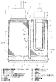
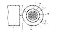
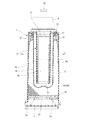
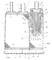
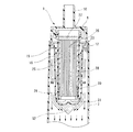
図1〜4は本発明に係る蒸発燃料処理装置としてのキャニスタのより具体的な第1の実施の形態を示す図で、特に図1はいわゆる双胴タイプのキャニスタの縦断面図を、図2は図1のA−A線に沿う断面図をそれぞれ示している。 1 to 4 are views showing a more specific first embodiment of a canister as an evaporative fuel processing apparatus according to the present invention. In particular, FIG. 1 is a longitudinal sectional view of a so-called twin-bottle type canister, and FIG. These respectively show sectional views along the line AA of FIG.
図1に示すキャニスタ1は、それぞれに例えばポリアミド樹脂等の樹脂材料にて筒状に形成された大小二つのケーシング、すなわち断面矩形状をなす角筒状の第1ケーシング2と断面円形状をなす円筒状の第2ケーシング3を並べて隔壁状のリブ4を介して相互に一体化したものである。これら二つのケーシング2,3はそれぞれのケーシング2,3の底部として機能するカバープレート5を共有していて、このカバープレート5が事後的に溶着等の手段にて接合・一体化されることで第1,第2ケーシング2,3が密閉される。これにより、第1,第2ケーシング2,3の内部空間は相互に隔離されている。
A
そして、後述するように、蒸発燃料および脱離(パージ)空気の通流方向において両者が直列関係となるようにそれらの第1ケーシング2と第2ケーシング3とが底部側の狭隘な連通路5aを介して相互に連通していて、それぞれのケーシング2,3の断面積に相当する所定の流路を形成している。
As will be described later, the
第1ケーシング2の一端の膨出部6は所定容積のチャンバ部を形成していて、この膨出部6には図示外の燃料タンクからの蒸発燃料を導入するための蒸発燃料導入部としてチャージポート7が開口形成されているとともに、後述する大気導入によって吸着材層14,20から離脱した燃料をエンジンの吸気系側に戻すための蒸発燃料排出部としてパージポート8が開口形成されている。他方、第2ケーシング3の一端の膨出部9も所定容積のチャンバ部を形成していて、この膨出部9には大気を導入するための大気導入部として大気ポート10が開口形成されている。
The bulging
第1ケーシング2には不織布あるいはウレタン等の所定厚みの通気性部材からなるシート状の複数のスクリーン11,12を介して活性炭等の粒状の吸着材13がフルに且つ満遍なく充填されていて、これをもって両端面にスクリーン11,12が介在した吸着材層14を形成している。
The
他方、第2ケーシング3では、大気ポート10に連通する円筒状の吸着材カートリッジ15を膨出部9に対して圧入固定してあるとともに、その吸着材カートリッジ15の外周に二重筒構造のかたちで有底円筒状のインナケーシング16をかぶせてある。これにより、第2ケーシング3内にはその内部流路の通流方向にインナケーシング16にて隔離された吸着材カートリッジ15が延在している。
On the other hand, in the
また、第2ケーシング3内にはインナケーシング16で隔離された部分を除いて不織布あるいはウレタン等の所定厚みの通気性部材からなる複数のスクリーン17,18を介して同じく活性炭等の粒状の吸着材19がフルに且つ満遍なく充填されていて、それによって両端面にスクリーン17,18が介在した吸着材層20を形成している。
In addition, a granular adsorbent such as activated carbon is also provided in the
第1ケーシング2側では、通気性を有しながらも剛性のある例えば樹脂製の多孔板状のグリッド21を下側のスクリーン12と重ねて配置してあり、そのスクリーン12がグリッド21にてバックアップされているとともに、グリッド21とそれに対向するカバープレート5側の内側底壁面との間には圧縮コイルスプリング22を介装してある。これによって吸着材層14を形成している吸着材13全体を適度な弾性力で弾性付勢して当該吸着材13全体を圧締保持している。
On the
このような構造は、第2ケーシング3側についても全く同様であって、通気性を有しながらも剛性のある樹脂製の多孔板状のグリッドを符号23で、グリッド23とそれに対向するカバープレート5側の内側底壁面との間に介装された圧縮コイルスプリングを符号24でそれぞれ示している。
Such a structure is exactly the same on the
このように、第1ケーシング2側および第2ケーシング3側共に吸着材層14,20の両側にスクリーン11,12または17,18とグリッド21または23とがあることによって、チャージポート7やパージポート8側さらには大気ポート10側、あるいは連通路5a側への吸着材13,19の漏れ出しが未然に防止されている。同時に、吸着材層14,20を形成している吸着材13,19に圧縮コイルスプリング22または24の力が加わることで第1,第2ケーシング2,3内での吸着材13,19の無用な移動あるいはいわゆる踊り現象が阻止されている。
Thus, the
そして、図1のキャニスタ1は、吸着材層14として機能する第1ケーシング2と同じく吸着材層20として機能する第2ケーシング3とを、それぞれのケーシング長が長手方向でオーバーラップするように並べて配置し、双方のケーシング2,3の他端部同士を連通路5aをもって連通させたものと理解することができる。
The
その結果として、後述するように、上記連通路5aを通して第1ケーシング2側と第2ケーシング3側の吸着材層14,20同士の間で行われる蒸発燃料および大気の流動が略U字状のものとなるように形成してある。
As a result, as will be described later, the flow of the evaporated fuel and the atmosphere performed between the
ただし、第1ケーシング2内の吸着材層14と第2ケーシング3内の吸着材層20とが直列の関係にさえなれば、双方のケーシング2,3の他端同士を突き合わせるようにして、その双方のケーシング2,3を同一軸線上に配置するようにしても良い。
However, as long as the
ここで、吸着材カートリッジ15は、筒状体としての例えば樹脂製の円筒状のカートリッジケース25内に、例えば活性炭を主成分としていわゆるハニカム構造に一体成形された円柱状の吸着材層26を装填したものであり、その上部および外周には不織布あるいはウレタン等の所定厚みの通気性部材からなる複数のスクリーン27または28を介装してあるとともに、カートリッジケース25の開放端25a側にはシール部材29を介装してある。吸着材層26はハニカム構造の多数の空隙を有している故に、長手方向において適度な通気性を有していることになる。
Here, the
なお、上記のハニカム構造に一体成形された円柱状の吸着材層26に代えて、第1,第2ケーシング2,3と同様にカートリッジケース25内に活性炭等の粒状の吸着材を充填しても良いことは言うまでもない。
Instead of the
また、吸着材カートリッジ15を隔離している有底円筒状のインナケーシング16は同じく樹脂製のもので、吸着材カートリッジ15との間に所定の中間隔離層30が形成されるようにその吸着材カートリッジ15よりも大径のものとしてある。そして、後述するように大気ポート10側から大気が導入された場合、上記中間隔離層30は吸着材カートリッジ15側から第2ケーシング3側への大気の通路として機能することから、インナケーシング16の底部には、吸着材カートリッジ15の開放端15a側からの大気の流れを左右にスムーズに案内するために整流膨出部31を形成してある。
The bottomed cylindrical
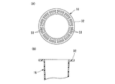
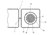
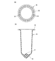
インナケーシング16の上端部には、図3にも示すように、円筒状の第2ケーシング3の内周に内接するフランジ部32を形成してあるとともに、このフランジ部32はスクリーン17と重合している。そして、このフランジ部32は後述するように中間隔離層30側から第2ケーシング3側への大気(パージ空気)の流入口として機能することから、図3に示すように多孔状のグリッド形状に形成して通気路33としての機能を具備させてある。
As shown in FIG. 3, a
したがって、このように構成されたキャニスタ1によれば、車両の停車時においては図示外の燃料タンクから発生する蒸発燃料がチャージポート7から第1ケーシング2内に導入されて、第1ケーシング2側の吸着材層14を形成している吸着材13のほか、第2ケーシング3側の吸着材層20を形成している吸着材19に吸着(チャージ)される。
Therefore, according to the
より具体的には、第1ケーシング2側の吸着材層14で吸着しきれなかった蒸発燃料はその吸着材層14の下方のグリッド21を通過し、さらに連通路5aを通過した上で第2ケーシング3側のグリッド23および吸着材層20を通過し、実質的に連通路5aにてU字状に流れの向きを変えることで第2ケーシング3側の吸着材層20に流入して、その吸着材層20を形成している吸着材19に吸着される。
More specifically, the evaporated fuel that could not be adsorbed by the
さらに、第2ケーシング3側の吸着材層20でも吸着しきれなかった蒸発燃料は、インナケーシング16の上端の通気路33から吸着材カートリッジ15とインナケーシング16との間の中間隔離層30に流入して、この中間隔離層30を通路として流通した上で吸着材カートリッジ15内に流入し、その吸着材カートリッジ15の吸着材層26によっても吸着される。そして、最終的には蒸発燃料が吸着された後の大気(空気)のみが大気ポート10から放出されることになる。
Further, the evaporated fuel that could not be adsorbed by the
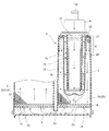
その一方、図4に示すように、エンジン稼働時には当該キャニスタ1を通して吸気を行うことにより大気ポート10から空気(大気)が導入され、その導入された空気は吸着材カートリッジ15内を通過するとともに、吸着材カートリッジ15から中間隔離層30を通路として流通した上で通気路33から第2ケーシング3内に流入する。その流入した空気は第2ケーシング3および第1ケーシング2内を通過してパージポート8からエンジン側に吸入される。
On the other hand, as shown in FIG. 4, when the engine is operating, air (atmosphere) is introduced from the
この導入空気の流れにより、吸着材カートリッジ15の吸着材層26や第2ケーシング3側の吸着材層20を形成している吸着材19のほか、第1ケーシング2側の吸着材層14を形成している吸着材13がいわゆるパージされ、吸着材層26や吸着材19,13に吸着されている蒸発燃料が脱離して導入空気とともにエンジン側に吸気されて燃焼処理される。そして、このパージによる蒸発燃料の脱離によって吸着材層26や吸着材19,13の性能が復活して再生されることになる。
In addition to the
この場合において、大気ポート10から導入されたパージのための空気は、吸着材カートリッジ15を通過した上でインナケーシング16の内底部に衝突して折り返され、さらに中間隔離層30を通路として通流した後に、再び通気路33において折り返されて第2ケーシング3内に流入することになる。そして、第2ケーシング3の上端部において流入口部として機能する通気路33近傍の空間、例えば図4の区間Bの空間は、図2から明らかなように円筒状の第2ケーシング3と同じく円筒状のインナケーシング16との組み合わせにより円環状のものとして形成されているため、円周方向においてデッドスペースが発生する余地がないだけでなく、その円周方向においてパージのための空気の流れが均一なものとなる。そのために、パージのための空気が減少することがなく、パージ効率が向上することになる。
In this case, the purge air introduced from the
ここで、実用上有効なパージ効率の向上効果を得るためには、第2ケーシング3のうち大気ポート10に近い一端部側、すなわち図4のB区間相当部でのインナケーシング16の外径をD1、同相当部での第2ケーシング3の内径をD2としたとき、そのD1とD2の関係を1.1<D2/D1<2.5に設定する必要があることが本発明者の実験等により判明した。その理由は、1.1未満であると第2ケーシング3の隅々まで吸着材19を充填できなくなるだけでなく、圧力損失が大きくなってキャニスタ1本来の要求性能を満たすことができなくなり、2.5を超えると、有効なパージ効率の向上が期待できなくなるからである。
Here, in order to obtain a practically effective purge efficiency improvement effect, the outer diameter of the
したがって、上記のようなパージ効率の向上効果が期待できる例えば図4のB区間相当部においてインナケーシング16および第2ケーシング3が共に円筒状のものであれば、それ以外に部位においては例えば第2ケーシング3が角筒状のものであってもよい。
Therefore, if the
なお、比較のために、円筒状のインナケーシング16と角筒状の第2ケーシング3との組み合わせとした場合の例を図5,6に示す。同図から明らかなように、第2ケーシング3が角筒状のものであると、特に第2ケーシング3の内隅部に相当する部分がデッドスペースS1となって、周方向でのパージのための空気の流れが均一にならず、パージ効率が低下することになる。
For comparison, FIGS. 5 and 6 show an example of a combination of the cylindrical
また、上記のようなパージを行ったとしても、先のチャージの際に相対的に上流側となる領域、すなわち第1ケーシング2側の吸着材層14を形成している吸着材13や、第2ケーシング3側の吸着材層20を形成している吸着材19の一部では、多かれ少なかれパージしきれなかった蒸発燃料が残存する。こうして残存した蒸発燃料は時間の経過とともに第1,第2ケーシング2,3の内部全体のほか吸着材カートリッジ15側にまで拡散・移動し(いわゆるマイグレーション現象)、そのままでは大気ポート10から蒸発燃料が大気中に放散または放出される可能性がある。
Further, even if purging as described above is performed, the adsorbent 13 forming the
その対策として本実施の形態では、第2ケーシング3と吸着材カートリッジ15とをつないでいる通路としての中間隔離層30の距離を可及的に大きく確保し、しかも幾重にも蛇行するようなかたちとしてあるため、上記のようにパージしきれずに第1,第2ケーシング2,3内に残存した蒸発燃料が吸着材カートリッジ15側に拡散しにくくその拡散が緩慢なものとなり、蒸発燃料が大気ポート10から放出されるのを抑制することができる。
As a countermeasure, in the present embodiment, the distance between the
しかも、吸着材カートリッジ15の吸着材層26は、その直径および体積が第1,第2ケーシング2,3側の吸着材層14,20よりも大幅に小さく、パージ時に大気ポート10から導入される空気の量と吸着材層26の容積との比(パージボリューム)が大きくなっている。そのために、パージ空気によって吸着材カートリッジ15の吸着材層26を充分にパージして、その吸着材層26から蒸発燃料を確実に脱離させることができる。それによって、吸着材カートリッジ15の吸着材層26の性能復活性または再生性が一段と向上することになる。
In addition, the
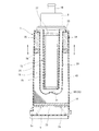
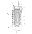
図7,8は本発明に係るキャニスタの第2の実施の形態を示す図で、図1,2と共通する部分には同一符号を付してある。 7 and 8 are views showing a second embodiment of a canister according to the present invention, and the same reference numerals are given to the parts common to FIGS.
この第2の実施の形態では、第2ケーシング43が断面矩形状の角筒状のものである点で第1の実施の形態と異なっている。そして、第2ケーシング43のうち大気ポート10に近い一端部側、すなわち図4のB区間相当部において、第2ケーシング43とインナケーシング16との間に、図1のスクリーン17に代えて、気流抵抗手段としての通気性のある気流抵抗体34を第2ケーシング43内の流路の通流方向に沿って設けてある。
The second embodiment is different from the first embodiment in that the
この気流抵抗体34は通流方向において二段の抵抗体35,36を組み合わせたもので、パージ空気の流れに着目した場合、例えば大気ポート10に近い上流側の抵抗体35として高発泡で密度の小さな疎の状態のウレタンを配置し、他方、大気ポート10から遠い下流側の抵抗体36として低発泡で密度の大きな密の状態のウレタンを配置してある。これにより、通気性のある気流抵抗体34全体としては、大気ポート10に近い上流側が密度の小さな疎の状態で通気抵抗が小さく、大気ポート10から遠い下流側が密度の大きな密の状態で通気抵抗が大きくなっていて、結果として気流抵抗体34に通流方向での密度勾配を持たせてある。
This
なお、上流側の抵抗体35としてウレタンを採用した場合、下流側の抵抗体36としては、ウレタンに代えて、例えば上流側の抵抗体35よりも密度の大きな例えば不織布の積層体等を採用することももちろん可能である。
When urethane is employed as the
この第2の実施の形態によれば、第2ケーシング43が角筒状のものであるために、図5,6に示したように第2ケーシング43の内隅部に相当する部分にデッドスペースS1が発生するかのような印象を受けるものの、大気ポート10から導入されたパージ空気が気流抵抗体34を通過することで、パージ空気の流れが適度に乱されて、第2ケーシング43の周方向でのパージ空気の流れが均一化される。これにより、図5,6に示したようなデッドスペースS1の発生がなくなり、パージ効率が向上することになる。
According to the second embodiment, since the
図10は本発明に係るキャニスタ1の第3の実施の形態を示し、図1に示した第1,第2ケーシング2,3の壁面の拡大断面図を示している。
10 shows a third embodiment of the
先にも述べたように、第1ケーシング2側の吸着材層14を形成している吸着材13や、第2ケーシング3側の吸着材層20を形成している吸着材19の一部では、多かれ少なかれパージしきれなかった蒸発燃料が残存し、こうして残存した蒸発燃料は時間の経過とともに第1,第2ケーシング2,3の内部全体あるは吸着材カートリッジ15側にまで拡散・移動することから、そのままでは大気ポート10から大気中に蒸発燃料が放散または放出される可能性があることは先に述べた。
As described above, in the adsorbent 13 forming the
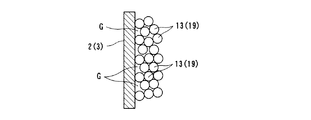
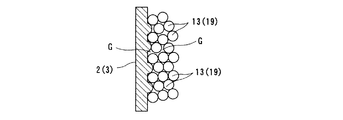
このような内部に残存した蒸発燃料の拡散・移動は、各吸着材層14,20を形成している粒状の吸着材13,13同士または19,19同士の間の空隙が多いほど顕著となり、例えば図9に示すように、第1,第2ケーシング2,3の内壁面が平滑面であれば粒状の吸着材13または19との間に比較的大きな空隙Gの発生が不可避である。
The diffusion and movement of the evaporated fuel remaining in the interior becomes more noticeable as there are more voids between the
そこで、第3の実施の形態では、図10に示すように、第1,第2ケーシング2,3の内壁面を凹凸形状にして、粒状の吸着材13または19との間にできる空隙Gを解消またはその大きさを可及的に小さくするようにしたものである。その結果として、第1,第2ケーシング2,3の内部に残存した蒸発燃料の拡散・移動を抑制する上で有利となる。
Therefore, in the third embodiment, as shown in FIG. 10, the inner wall surfaces of the first and
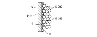
ここで、図11に示すように、第1,第2ケーシング2,3の内壁面を凹凸形状にするのに代えて、第1,第2ケーシング2,3の内壁面にゴム等の弾性のあるシート37を貼着し、充填された粒状の吸着材13または19によってそのシート37を積極的に弾性変形させるようにしても上記と同様の効果が発揮される。
Here, instead of making the inner wall surfaces of the first and
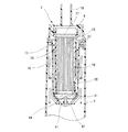
図12,13は本発明に係るキャニスタ1の第4の実施の形態を示し、図1と共通する部分には同一符号を付してある。
12 and 13 show a fourth embodiment of a
この第4の実施の形態では、インナケーシング16の底部に円錐状の突起部38を一体に形成して、そのインナケーシング16の底部側でのパージ空気の整流効果を得るようしたものである。
In the fourth embodiment, a
この突起部38がない場合、図14に示すように、インナケーシング16の底部に整流膨出部31を形成したことによって、インナケーシング16の底部外側にはパージ空気が届きにくい略三角形状のデッドスペースS2が発生する可能性がある。
When this
その対策として、図12,13に示すように、インナケーシング16の底部に円錐状の突起部38を一体に形成してあると、上記デッドスペースS2の発生を解消することができ、パージ効率の向上に一段と寄与することができるようになる。
As a countermeasure against this, as shown in FIGS. 12 and 13, if the
ここで、インナケーシング16の底部に図12,13のような円錐状の突起部38を一体に形成するのに代えて、図15に示すように、整流膨出部31が形成されたインナケーシング16の底部外側に嵌合ボス部39を形成する一方、上記突起部38に相当する断面パラソル状のエンドキャップ40を別に形成し、このエンドキャップ40を嵌合ボス部39に嵌合保持させるようにしても良い。
Here, instead of integrally forming the
また、図16に示すように、インナケーシング16の底部外側に円錐状の突起部41を一体に形成するとともに、底部内側に嵌合ボス部42を形成する一方、上記整流膨出部31に相当するボトムピース44を別に形成しておき、このボトムピース44を上記嵌合ボス部42に嵌合保持させるようにしても良い。
As shown in FIG. 16, a
1…蒸発燃料処理装置としてのキャニスタ
2…第1ケーシング
3…第2ケーシング
7…チャージポート(蒸発燃料導入部)
8…パージポート(蒸発燃料排出部)
10…大気ポート(大気導入部)
13…吸着材
14…吸着材層
15…吸着材カートリッジ
16…インナケーシング
19…吸着材
20…吸着材層
25…カートリッジケース(筒状体)
26…吸着材層
30…中間隔離層
33…通気路
34…気流抵抗体(気流抵抗手段)
35…抵抗体
36…抵抗体
43…第2ケーシング
DESCRIPTION OF
8. Purge port (evaporated fuel discharge part)
10 ... Air port (atmosphere introduction part)
DESCRIPTION OF
26 ...
35 ...
Claims (5)
上記ケーシング内において流路の通流方向に延在していて、一端が上記大気導入部に連通するとともに他端が開口している筒状体と、
上記筒状体の外周側に二重筒構造のかたちで外挿されて、その筒状体をケーシングの内部空間から隔離している有底筒状のインナケーシングと、
上記筒状体とインナケーシングとの間の中間隔離層を除いてその筒状体の内部およびケーシングの内部にそれぞれ充填された吸着材と、
を備えていて、
上記中間隔離層がケーシングの大気導入部側の端部において当該ケーシングの内部空間と連通していることより、その中間隔離層がケーシングの内部での流路の一部として機能するようになっているとともに、
上記ケーシングおよびインナケーシングのうち少なくとも大気導入部側の端部が共に断面円形状のものとして形成されていることを特徴とする蒸発燃料処理装置。 An evaporative fuel introduction part for introducing evaporative fuel and an evaporative fuel discharge part for evaporating the evaporative fuel are respectively provided at one end of a casing forming a flow path therein, and the atmosphere is introduced into the other end of the casing An evaporative fuel processing apparatus provided with an air introduction part,
A cylindrical body that extends in the flow direction of the flow path in the casing, has one end communicating with the atmosphere introduction portion and the other end being open;
A bottomed cylindrical inner casing that is extrapolated in the form of a double cylinder structure on the outer peripheral side of the cylindrical body and isolates the cylindrical body from the internal space of the casing;
The adsorbent filled in the inside of the cylindrical body and the inside of the casing except for the intermediate isolation layer between the cylindrical body and the inner casing,
With
Since the intermediate isolation layer communicates with the internal space of the casing at the end of the casing on the atmosphere introduction side, the intermediate isolation layer functions as a part of the flow path inside the casing. And
An evaporative fuel processing apparatus, wherein at least an end portion on the atmosphere introduction portion side of the casing and the inner casing is formed to have a circular cross section.
上記ケーシング内において流路の通流方向に延在していて、一端が上記大気導入部に連通するとともに他端が開口している筒状体と、
上記筒状体の外周側に二重筒構造のかたちで外挿されて、その筒状体をケーシングの内部空間から隔離している有底筒状のインナケーシングと、
上記筒状体とインナケーシングとの間の中間隔離層を除いてその筒状体の内部およびケーシングの内部にそれぞれ充填された吸着材と、
を備えていて、
上記中間隔離層がケーシングの大気導入部側の端部において当該ケーシングの内部空間と連通していることより、その中間隔離層がケーシングの内部での流路の一部として機能するようになっているとともに、
上記ケーシングのうち少なくとも大気導入部側の端部が断面矩形状のものであるのに対して、上記インナケーシングのうち少なくとも大気導入部側の端部が断面円形状のものとして形成されていて、
さらに上記中間隔離層からケーシング内への大気流入口部近傍に、空気の流れ方向で密度勾配を持たせた気流抵抗手段を設けたことを特徴とする蒸発燃料処理装置。 An evaporative fuel introduction part for introducing evaporative fuel and an evaporative fuel discharge part for evaporating the evaporative fuel are respectively provided at one end of a casing forming a flow path therein, and the atmosphere is introduced into the other end of the casing. An evaporative fuel processing apparatus provided with an air introduction part,
A cylindrical body that extends in the flow direction of the flow path in the casing, has one end communicating with the atmosphere introduction portion and the other end being open;
A bottomed cylindrical inner casing that is extrapolated in the form of a double cylinder structure on the outer peripheral side of the cylindrical body and isolates the cylindrical body from the internal space of the casing;
The adsorbent filled in the inside of the cylindrical body and the inside of the casing except for the intermediate isolation layer between the cylindrical body and the inner casing,
With
Since the intermediate isolation layer communicates with the internal space of the casing at the end of the casing on the atmosphere introduction side, the intermediate isolation layer functions as a part of the flow path inside the casing. And
At least the end on the atmosphere introduction part side of the casing is rectangular in cross section, whereas at least the end on the atmosphere introduction part side of the inner casing is formed as a circular cross section,
Furthermore, an evaporative fuel processing apparatus is provided with airflow resistance means having a density gradient in the air flow direction in the vicinity of the air inlet from the intermediate isolation layer into the casing.
Priority Applications (1)
| Application Number | Priority Date | Filing Date | Title |
|---|---|---|---|
| JP2008320537A JP2010144549A (en) | 2008-12-17 | 2008-12-17 | Evaporated fuel treatment device |
Applications Claiming Priority (1)
| Application Number | Priority Date | Filing Date | Title |
|---|---|---|---|
| JP2008320537A JP2010144549A (en) | 2008-12-17 | 2008-12-17 | Evaporated fuel treatment device |
Publications (1)
| Publication Number | Publication Date |
|---|---|
| JP2010144549A true JP2010144549A (en) | 2010-07-01 |
Family
ID=42565241
Family Applications (1)
| Application Number | Title | Priority Date | Filing Date |
|---|---|---|---|
| JP2008320537A Pending JP2010144549A (en) | 2008-12-17 | 2008-12-17 | Evaporated fuel treatment device |
Country Status (1)
| Country | Link |
|---|---|
| JP (1) | JP2010144549A (en) |
Cited By (5)
| Publication number | Priority date | Publication date | Assignee | Title |
|---|---|---|---|---|
| JP2012193662A (en) * | 2011-03-16 | 2012-10-11 | Aisan Industry Co Ltd | Evaporated fuel treating device |
| JP2012225167A (en) * | 2011-04-15 | 2012-11-15 | Aisan Industry Co Ltd | Fuel vapor processing devices |
| JP2013011208A (en) * | 2011-06-29 | 2013-01-17 | Mahle Filter Systems Japan Corp | Evaporation fuel treating apparatus |
| JP2015137610A (en) * | 2014-01-23 | 2015-07-30 | フタバ産業株式会社 | Canister |
| US12247530B2 (en) * | 2023-04-20 | 2025-03-11 | Futaba Industrial Co., Ltd. | Canister |
Citations (8)
| Publication number | Priority date | Publication date | Assignee | Title |
|---|---|---|---|---|
| JPH0324867Y2 (en) * | 1984-03-31 | 1991-05-30 | ||
| JPH05280435A (en) * | 1991-07-12 | 1993-10-26 | Toyoda Gosei Co Ltd | Evaporated fuel treating device |
| JPH0627818Y2 (en) * | 1988-08-29 | 1994-07-27 | 株式会社土屋製作所 | Carbon canister |
| JPH10227260A (en) * | 1997-02-13 | 1998-08-25 | Aisan Ind Co Ltd | Canister |
| JP2000186635A (en) * | 1998-12-22 | 2000-07-04 | Aisan Ind Co Ltd | Canister |
| JP2002030998A (en) * | 2000-07-18 | 2002-01-31 | Aisan Ind Co Ltd | Vehicle canister |
| JP2008106610A (en) * | 2006-10-23 | 2008-05-08 | Mahle Filter Systems Japan Corp | Evaporative fuel processing equipment |
| JP4173065B2 (en) * | 2002-07-16 | 2008-10-29 | 株式会社マーレ フィルターシステムズ | Evaporative fuel processing equipment |
-
2008
- 2008-12-17 JP JP2008320537A patent/JP2010144549A/en active Pending
Patent Citations (8)
| Publication number | Priority date | Publication date | Assignee | Title |
|---|---|---|---|---|
| JPH0324867Y2 (en) * | 1984-03-31 | 1991-05-30 | ||
| JPH0627818Y2 (en) * | 1988-08-29 | 1994-07-27 | 株式会社土屋製作所 | Carbon canister |
| JPH05280435A (en) * | 1991-07-12 | 1993-10-26 | Toyoda Gosei Co Ltd | Evaporated fuel treating device |
| JPH10227260A (en) * | 1997-02-13 | 1998-08-25 | Aisan Ind Co Ltd | Canister |
| JP2000186635A (en) * | 1998-12-22 | 2000-07-04 | Aisan Ind Co Ltd | Canister |
| JP2002030998A (en) * | 2000-07-18 | 2002-01-31 | Aisan Ind Co Ltd | Vehicle canister |
| JP4173065B2 (en) * | 2002-07-16 | 2008-10-29 | 株式会社マーレ フィルターシステムズ | Evaporative fuel processing equipment |
| JP2008106610A (en) * | 2006-10-23 | 2008-05-08 | Mahle Filter Systems Japan Corp | Evaporative fuel processing equipment |
Cited By (8)
| Publication number | Priority date | Publication date | Assignee | Title |
|---|---|---|---|---|
| JP2012193662A (en) * | 2011-03-16 | 2012-10-11 | Aisan Industry Co Ltd | Evaporated fuel treating device |
| US8733325B2 (en) | 2011-03-16 | 2014-05-27 | Aisan Kogyo Kabushiki Kaisha | Evaporated fuel treating device |
| JP2012225167A (en) * | 2011-04-15 | 2012-11-15 | Aisan Industry Co Ltd | Fuel vapor processing devices |
| JP2013011208A (en) * | 2011-06-29 | 2013-01-17 | Mahle Filter Systems Japan Corp | Evaporation fuel treating apparatus |
| JP2015137610A (en) * | 2014-01-23 | 2015-07-30 | フタバ産業株式会社 | Canister |
| WO2015111575A1 (en) * | 2014-01-23 | 2015-07-30 | フタバ産業株式会社 | Canister |
| US10138848B2 (en) | 2014-01-23 | 2018-11-27 | Futaba Industrial Co., Ltd. | Canister |
| US12247530B2 (en) * | 2023-04-20 | 2025-03-11 | Futaba Industrial Co., Ltd. | Canister |
Similar Documents
| Publication | Publication Date | Title |
|---|---|---|
| JP2012007501A (en) | Canister | |
| JP5220631B2 (en) | Evaporative fuel processing equipment | |
| JP5976381B2 (en) | Evaporative fuel processing equipment | |
| JP5940932B2 (en) | Canister | |
| JP2003193917A (en) | Evaporated fuel adsorbent and air cleaner | |
| JP2010144549A (en) | Evaporated fuel treatment device | |
| CA2781227C (en) | Fuel vapor processing apparatus | |
| JP2008202604A (en) | Evaporative fuel handling device | |
| AU2005216914A1 (en) | X-spring volume compensator for automotive carbon canister | |
| US10590889B2 (en) | Canister | |
| JP2009127603A (en) | Canister | |
| JP7181254B2 (en) | Evaporative fuel processing device | |
| JP2019105255A (en) | Canister | |
| CN107407232B (en) | Filtering tank | |
| JP2010031711A (en) | Canister | |
| JP2012007503A (en) | Canister | |
| JP2015048841A (en) | Canister | |
| JP2013130084A (en) | Canister | |
| CN112282979A (en) | Evaporated fuel treatment device | |
| JP2009250152A (en) | Canister | |
| JP2021025440A (en) | Evaporated fuel treatment device | |
| JP2008038675A (en) | Canister | |
| JP2012002112A (en) | Canister | |
| JP5841360B2 (en) | Evaporative fuel processing equipment | |
| JP2019019739A (en) | Evaporative fuel processing equipment |
Legal Events
| Date | Code | Title | Description |
|---|---|---|---|
| A621 | Written request for application examination |
Free format text: JAPANESE INTERMEDIATE CODE: A621 Effective date: 20111214 |
|
| A977 | Report on retrieval |
Free format text: JAPANESE INTERMEDIATE CODE: A971007 Effective date: 20130131 |
|
| A131 | Notification of reasons for refusal |
Free format text: JAPANESE INTERMEDIATE CODE: A131 Effective date: 20130205 |
|
| A02 | Decision of refusal |
Free format text: JAPANESE INTERMEDIATE CODE: A02 Effective date: 20130604 |