JP2010144516A - Precombustor of gas engine - Google Patents
Precombustor of gas engine Download PDFInfo
- Publication number
- JP2010144516A JP2010144516A JP2008319104A JP2008319104A JP2010144516A JP 2010144516 A JP2010144516 A JP 2010144516A JP 2008319104 A JP2008319104 A JP 2008319104A JP 2008319104 A JP2008319104 A JP 2008319104A JP 2010144516 A JP2010144516 A JP 2010144516A
- Authority
- JP
- Japan
- Prior art keywords
- combustion chamber
- gas engine
- main combustion
- chamber
- fuel mixture
- Prior art date
- Legal status (The legal status is an assumption and is not a legal conclusion. Google has not performed a legal analysis and makes no representation as to the accuracy of the status listed.)
- Pending
Links
- 238000002485 combustion reaction Methods 0.000 claims abstract description 91
- 239000000446 fuel Substances 0.000 claims abstract description 75
- 239000000203 mixture Substances 0.000 claims abstract description 47
- 239000007788 liquid Substances 0.000 claims abstract description 35
- 238000002347 injection Methods 0.000 claims description 16
- 239000007924 injection Substances 0.000 claims description 16
- 230000002708 enhancing effect Effects 0.000 abstract 1
- 239000007789 gas Substances 0.000 description 34
- 230000006835 compression Effects 0.000 description 5
- 238000007906 compression Methods 0.000 description 5
- 239000002737 fuel gas Substances 0.000 description 2
- 230000000694 effects Effects 0.000 description 1
- 238000004880 explosion Methods 0.000 description 1
- 230000000630 rising effect Effects 0.000 description 1
Images
Classifications
-
- Y—GENERAL TAGGING OF NEW TECHNOLOGICAL DEVELOPMENTS; GENERAL TAGGING OF CROSS-SECTIONAL TECHNOLOGIES SPANNING OVER SEVERAL SECTIONS OF THE IPC; TECHNICAL SUBJECTS COVERED BY FORMER USPC CROSS-REFERENCE ART COLLECTIONS [XRACs] AND DIGESTS
- Y02—TECHNOLOGIES OR APPLICATIONS FOR MITIGATION OR ADAPTATION AGAINST CLIMATE CHANGE
- Y02T—CLIMATE CHANGE MITIGATION TECHNOLOGIES RELATED TO TRANSPORTATION
- Y02T10/00—Road transport of goods or passengers
- Y02T10/10—Internal combustion engine [ICE] based vehicles
- Y02T10/12—Improving ICE efficiencies
-
- Y—GENERAL TAGGING OF NEW TECHNOLOGICAL DEVELOPMENTS; GENERAL TAGGING OF CROSS-SECTIONAL TECHNOLOGIES SPANNING OVER SEVERAL SECTIONS OF THE IPC; TECHNICAL SUBJECTS COVERED BY FORMER USPC CROSS-REFERENCE ART COLLECTIONS [XRACs] AND DIGESTS
- Y02—TECHNOLOGIES OR APPLICATIONS FOR MITIGATION OR ADAPTATION AGAINST CLIMATE CHANGE
- Y02T—CLIMATE CHANGE MITIGATION TECHNOLOGIES RELATED TO TRANSPORTATION
- Y02T10/00—Road transport of goods or passengers
- Y02T10/10—Internal combustion engine [ICE] based vehicles
- Y02T10/30—Use of alternative fuels, e.g. biofuels
Landscapes
- Combustion Methods Of Internal-Combustion Engines (AREA)
- Output Control And Ontrol Of Special Type Engine (AREA)
Abstract
Description
本発明は、主燃焼室から予燃焼室内に導入される加圧混合気に旋回流を与えて導入することにより、予燃焼室内の加圧混合気を均一な状態に保持するようにしたガスエンジンの予燃焼器に関する。 The present invention relates to a gas engine in which a pressurized air-fuel mixture introduced from a main combustion chamber into a pre-combustion chamber is introduced with a swirling flow to keep the pressurized air-fuel mixture in the pre-combustion chamber in a uniform state. Relates to a pre-combustor.
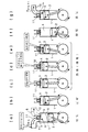
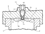
図4はガスエンジンの構成の一例と作動を示す説明図、図5は予燃焼器の構成の一例を示す断面図であり、ガスエンジンは、図4に示すように、シリンダ1に収容されるピストン2とシリンダヘッド3との間に主燃焼室4を形成しており、前記シリンダヘッド3には、主燃焼室4に燃料ガスと空気が混合した吸気5を吸気弁6により供給する吸気ポート7と、主燃焼室4の排気ガス8を排気弁9により排出する排気ポート10が備えられている。
FIG. 4 is an explanatory view showing an example of the configuration and operation of the gas engine, FIG. 5 is a cross-sectional view showing an example of the configuration of the precombustor, and the gas engine is accommodated in the
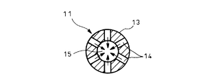
更に、シリンダヘッド3には予燃焼器11が設置されている。予燃焼器11は、図5に示すように、ガスエンジンの圧縮行程で主燃焼室4内の希薄混合気が加圧された加圧混合気12を口金13に設けた連通口14を介して導入するようにした予燃焼室15を有している。予燃焼室15の上部(連通口14に対して反対側)には液体燃料噴射弁16が設けてあり、該液体燃料噴射弁16により予燃焼室15内の加圧混合気12中に軽油等の液体燃料17を噴射することで該液体燃料17を着火燃焼せしめ、この着火火炎18を連通口14から主燃焼室4内の希薄混合気中に噴出して希薄混合気を燃焼させるようにしている。前記予燃焼器11に設けられる連通口14は、図6に示すように、口金13の軸中心に対して放射方向に複数個形成している。
Further, a
次に、図4を参照してガスエンジンの作動を説明する。 Next, the operation of the gas engine will be described with reference to FIG.
図4(a)は吸気行程を示し、ピストン2の下降時に吸気ポート7の吸気弁6を開けて、燃料ガスと空気が混合された吸気5を主燃焼室4に吸入している。
FIG. 4A shows the intake stroke, and when the
図4(b)は、圧縮行程を示し、ピストン2の上昇により主燃焼室4の希薄混合気を圧縮している。この時、図5に示すように主燃焼室4の加圧された加圧混合気12が予燃焼器11の口金に設けた連通口14を通して予燃焼室15に導入される。
FIG. 4B shows the compression stroke, and the lean air-fuel mixture in the
図4(c)は、液体燃料の噴射状態を示し、ピストン2の上死点の直前において、図5の液体燃料噴射弁16から予燃焼室15内に導入される加圧混合気12中に軽油等の液体燃料17を噴射し、該液体燃料17を着火燃焼させる。
FIG. 4C shows the injection state of the liquid fuel. Just before the top dead center of the
図4(d)は、着火火炎の噴出状態を示し、ピストン2の上死点の直後において、図5の予燃焼室15内で着火燃焼された着火火炎18が連通口14を通して主燃焼室4に噴出されることにより主燃焼室4内の希薄混合気に着火される。
FIG. 4D shows a state in which an ignition flame is ejected. Immediately after the top dead center of the
図4(e)は、主燃焼室4内での燃焼状態を示し、主燃焼室4の着火された希薄混合気が一気に燃焼される。上記図4(c)、(d)、(e)は燃焼(爆発)行程を表わす。
FIG. 4E shows a combustion state in the
図4(f)は、膨張行程を示し、主燃焼室4内での燃焼によってピストン2が押し下げられて仕事が行われる。
FIG. 4F shows the expansion stroke, and the
図4(g)は、排気行程を示し、ピストン2の上昇時に排気ポート10の排気弁9を開けて、主燃焼室4内の排気ガス8を排気している。
FIG. 4G shows the exhaust stroke. When the
前記したガスエンジンの予燃焼器の一般的技術水準を示すものとしては、特許文献1、特許文献2がある。
しかし、前記のようなガスエンジンの予燃焼器11においては、主燃焼室4から予燃焼室15に導入される加圧混合気12に、液体燃料噴射弁16から液体燃料17を噴射して着火燃焼させる際に、予燃焼室15内での液体燃料17の着火燃焼にバラツキが生じて予燃焼室15内に均一温度の着火火炎を形成できないという問題を有していた。
However, in the
特許文献1及び2に示されるように、従来の予燃焼器11に設けられている連通口14は、図6に示すように、口金13の軸中心に対して放射方向に形成されているため、圧縮行程において主燃焼室4で加圧された加圧混合気12は、図7に示すように連通口14により予燃焼室15の軸中心に向かって導入された後、予燃焼室15の軸中心を上昇して天井部に当たり、続いて外方に向かった後下方に向かうという上下方向の流れを形成する。しかし、このような加圧混合気12の上下方向の流れでは液体燃料噴射弁16から噴射される液体燃料17と加圧混合気12とが十分に混合されない。このため、液体燃料噴射弁16から噴射された液体燃料17は予燃焼室15内の上部位置において着火され、且つ上部位置の液体燃料17の濃度は高いために予燃焼室15内の上部位置の温度は高く、これに対して下部位置の温度は低いという温度差が生じる。
As shown in
一方、前記液体燃料噴射弁16から予燃焼室15内に噴射した液体燃料17が着火燃焼し、その着火火炎18が連通口14を通って主燃焼室4に噴出されるまでの時間は瞬時であるため、前記したように予燃焼室15内に温度差があると、例えば先ず温度が低い着火火炎18が連通口14から噴出された後、温度が高い着火火炎18が連通口14から噴出されるようになり、このために、主燃焼室4の希薄混合気を瞬時に均一に燃焼させることができず、良好な燃焼が達成できないという問題が生じていた。
又、前記液体燃料噴射弁16を備えることに代えて、予燃焼室15に火花点火器を備える場合があり、この場合には、主燃焼室4で加圧された加圧混合気12が予燃焼室15に導入されて予燃焼室内の残留ガス(前サイクルの既燃ガス)と混合され、その混合ガスに火花点火器によって点火するようにしているが、前記したように、予燃焼室15に導入される加圧混合気12の上下方向の流れでは加圧混合気12と残留ガスとの十分な混合が行われず、予燃焼室15内に温度の不均一及び加圧混合気12の濃度の不均一が生じ、そのために、火花点火器による点火が不安定になるという問題がある。
On the other hand, the
Further, instead of providing the liquid
本発明は、かかる従来技術の課題に鑑みてなしたもので、主燃焼室から予燃焼室内に導入される加圧混合気に旋回流を与えて導入することにより、予燃焼室内の加圧混合気を均一な状態に保持するようにしたガスエンジンの予燃焼器を提供することを目的とする。 The present invention has been made in view of the problems of the prior art, and by introducing a swirl flow into a pressurized mixture introduced from the main combustion chamber into the precombustion chamber, the pressurized mixing in the precombustion chamber is performed. It is an object of the present invention to provide a pre-combustor for a gas engine that keeps the air in a uniform state.
本発明は、シリンダヘッドの主燃焼室と連通口により連通した予燃焼室を有するガスエンジンの予燃焼器であって、予燃焼室と主燃焼室を連通する連通口が、予燃焼室の軸中心に対してオフセット配置したオフセット口により形成され、主燃焼室内の加圧混合気がオフセット口により予燃焼室内に旋回流を形成して導入されるようにしたことを特徴とするガスエンジンの予燃焼器、に係るものである。
上記ガスエンジンの予燃焼器において、前記オフセット口が予燃焼室の内部から外方へ向かって下り勾配に形成されていることは好ましい。
The present invention relates to a pre-combustor for a gas engine having a pre-combustion chamber that communicates with a main combustion chamber of a cylinder head through a communication port, and the communication port that communicates the pre-combustion chamber and the main combustion chamber has a shaft of the pre-combustion chamber. The gas engine is preliminarily formed by an offset port arranged offset from the center, and the pressurized air-fuel mixture in the main combustion chamber is introduced into the precombustion chamber by forming a swirl flow through the offset port. Combustor.
In the pre-combustor of the gas engine, it is preferable that the offset port is formed in a downward gradient from the inside of the pre-combustion chamber to the outside.
又、上記ガスエンジンの予燃焼器において、前記予燃焼室は液体燃料を噴射するための液体燃料噴射弁を有していてもよい。 In the precombustor of the gas engine, the precombustion chamber may have a liquid fuel injection valve for injecting liquid fuel.
又、上記ガスエンジンの予燃焼器において、前記予燃焼室は火花点火器を有していてもよい。 In the precombustor of the gas engine, the precombustion chamber may have a spark igniter.
本発明のガスエンジンの予燃焼器によれば、ガスエンジンの圧縮行程において主燃焼室で加圧された加圧混合気が、予燃焼室の軸中心に対してオフセット配置されたオフセット口を通して予燃焼室内に導入されるため、予燃焼室内に旋回流が形成され、よって、予燃焼室内の加圧混合気の濃度が均一に保持され且つ均一な温度に保持される効果がある。 According to the gas engine precombustor of the present invention, the pressurized air-fuel mixture pressurized in the main combustion chamber in the compression stroke of the gas engine is preliminarily passed through the offset port that is offset with respect to the axial center of the precombustion chamber. Since it is introduced into the combustion chamber, a swirl flow is formed in the pre-combustion chamber, so that the concentration of the pressurized air-fuel mixture in the pre-combustion chamber is maintained uniformly and at a uniform temperature.
従って、前記予燃焼室に液体燃料を噴射するための液体燃料噴射弁を備えている場合には、先ず、主燃焼室で加圧された加圧混合気が予燃焼室に旋回導入されることにより、予燃焼室内の残留ガス(前サイクルの既燃ガス)との混合が促進されて均一温度に保持された状態のところへ液体燃料噴射弁から液体燃料が噴射されて旋回する加圧混合気と効果的に混合されるため、予燃焼室内での着火燃焼が瞬時に均一に行われるようになり、よって予燃焼室内の温度が均一に保持される。従って、予燃焼室内の均一温度の着火火炎がオフセット口から主燃焼室内に噴出されるようになるため、主燃焼室の希薄混合気を良好に燃焼させられるという優れた効果を奏し得る。 Therefore, when a liquid fuel injection valve for injecting liquid fuel into the precombustion chamber is provided, first, the pressurized air-fuel mixture pressurized in the main combustion chamber is swirled into the precombustion chamber. By this, the mixture with the residual gas in the pre-combustion chamber (the burned gas of the previous cycle) is promoted, and the pressurized fuel-air mixture that is swung by injecting the liquid fuel from the liquid fuel injection valve to the state where it is maintained at a uniform temperature Therefore, the ignition combustion in the pre-combustion chamber is instantaneously and uniformly performed, so that the temperature in the pre-combustion chamber is kept uniform. Accordingly, since the ignition flame having a uniform temperature in the pre-combustion chamber is ejected from the offset port into the main combustion chamber, it is possible to achieve an excellent effect that the lean air-fuel mixture in the main combustion chamber can be burned well.
一方、前記予燃焼室に火花点火器を備えている場合には、主燃焼室で加圧された加圧混合気が予燃焼室に旋回導入され、予燃焼室内の残留ガス(前サイクルの既燃ガス)と効果的に混合されて予燃焼室15内の加圧混合気12の濃度が均一になり且つ温度が均一に保持されるため、火花点火器による確実な点火が可能になる効果がある。
On the other hand, when the pre-combustion chamber is provided with a spark igniter, the pressurized air-fuel mixture pressurized in the main combustion chamber is swirled and introduced into the pre-combustion chamber, and the residual gas in the pre-combustion chamber (existing in the previous cycle). And the temperature of the pressurized air-
以下、本発明の実施の形態を添付図面を参照して説明する。 Embodiments of the present invention will be described below with reference to the accompanying drawings.
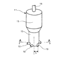
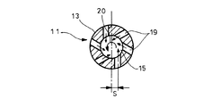
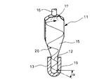
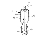
図1は本発明におけるガスエンジンの予燃焼器の斜視図、図2は図1の連通口部をA−A方向から見た切断平面図、図3aは図1の予燃焼室を透視した斜視図であり、予燃焼室15には液体燃料17を噴射する液体燃料噴射弁16を備えた場合を示しており、図5の構成も参照して説明する。
1 is a perspective view of a pre-combustor of a gas engine according to the present invention, FIG. 2 is a cut-away plan view of the communication port portion of FIG. 1 viewed from the direction AA, and FIG. 3A is a perspective view of the pre-combustion chamber of FIG. It is a figure and the case where the
本発明では、予燃焼器11の予燃焼室15を主燃焼室4に連通するための口金13に設けられる連通口を、予燃焼室15の軸中心に対してオフセット配置S(口金13に対して接線の方向に配置)した複数のオフセット口19により形成しており、該オフセット口19によって主燃焼室4内の加圧混合気が、旋回流20を形成して予燃焼室15内に導入されるようにしている。
In the present invention, the communication port provided in the
又、オフセット口19は、図3に示すように、予燃焼室15の内部から外方へ向かって所要角度αの下り勾配になるように形成している。
Further, as shown in FIG. 3, the offset
次に、上記図示例の作動を説明する。 Next, the operation of the illustrated example will be described.
ガスエンジンの圧縮行程においては主燃焼室4で加圧された加圧混合気12は、図1〜図3に示すように口金13に設けたオフセット口19を通して予燃焼室15に導入される。この時、オフセット口19は予燃焼室15の軸中心に対してオフセット配置S(口金13に対して接線方向に配置)されているため、加圧混合気12は旋回流20を形成して予燃焼室15内に導入されるようになる。この時、前記オフセット口19を図3に示すように、予燃焼室15の内部から外方へ向かって所要角度αの下り勾配になるように形成しているので、予燃焼室15に導入される加圧混合気12は予燃焼室15内を上昇しながら旋回する安定した旋回流20を形成するようになる。
In the compression stroke of the gas engine, the pressurized air-
従って、予燃焼室15内における均一温度の着火火炎18がオフセット口19から主燃焼室4内に噴出されることになるため、主燃焼室4では希薄混合気が瞬時に均一に燃焼するようになって、良好な燃焼が達成される。
Therefore, since the
又、着火火炎18がオフセット口19から主燃焼室4に噴出される際にもオフセット口19によって旋回流が形成されることになるため、主燃焼室4内の隅々まで着火火炎18が供給されることにより主燃焼室4内の希薄混合気の燃焼が更に向上されるようになる。
Also, when the
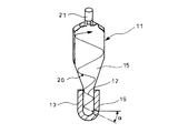
図3bは、図3aのように、前記予燃焼室15に液体燃料噴射弁16を備えた構成に代えて、前記予燃焼室15にスパークプラグ等の火花点火器21を備えた場合を示している。
FIG. 3b shows a case where a
図3bの形態では、主燃焼室で加圧された加圧混合気12が予燃焼室15に導入されて予燃焼室15内の残留ガス(前サイクルの既燃ガス)と混合される際に、加圧混合気12が旋回していることにより残留ガスとの混合が促進され、よって予燃焼室15内の加圧混合気12の濃度が均一で且つ温度が均一に保持されるため、火花点火器21による点火が確実に行われるようになる。
In the form of FIG. 3 b, when the pressurized air-
なお、本発明のガスエンジンの予燃焼器は、上記形態にのみ限定されることなく、本発明の要旨を逸脱しない範囲内において種々変更を加え得ることは勿論である。 The pre-combustor of the gas engine of the present invention is not limited to the above-described form, and can be variously modified without departing from the gist of the present invention.
3 シリンダヘッド
4 主燃焼室
11 予燃焼器
12 加圧混合気
15 予燃焼室
16 液体燃料噴射弁
17 液体燃料
18 着火火炎
19 オフセット口
20 旋回流
21 火花点火器
S オフセット配置
α 下り勾配角度
DESCRIPTION OF
Claims (4)
Priority Applications (1)
| Application Number | Priority Date | Filing Date | Title |
|---|---|---|---|
| JP2008319104A JP2010144516A (en) | 2008-12-16 | 2008-12-16 | Precombustor of gas engine |
Applications Claiming Priority (1)
| Application Number | Priority Date | Filing Date | Title |
|---|---|---|---|
| JP2008319104A JP2010144516A (en) | 2008-12-16 | 2008-12-16 | Precombustor of gas engine |
Publications (1)
| Publication Number | Publication Date |
|---|---|
| JP2010144516A true JP2010144516A (en) | 2010-07-01 |
Family
ID=42565211
Family Applications (1)
| Application Number | Title | Priority Date | Filing Date |
|---|---|---|---|
| JP2008319104A Pending JP2010144516A (en) | 2008-12-16 | 2008-12-16 | Precombustor of gas engine |
Country Status (1)
| Country | Link |
|---|---|
| JP (1) | JP2010144516A (en) |
Cited By (6)
| Publication number | Priority date | Publication date | Assignee | Title |
|---|---|---|---|---|
| CN103452704A (en) * | 2013-08-09 | 2013-12-18 | 蔡肃民 | Miniature turbojet midair windmill ignition device |
| WO2015060236A1 (en) * | 2013-10-21 | 2015-04-30 | 三菱重工業株式会社 | Prechamber type gas engine |
| EP3009641A1 (en) * | 2014-10-17 | 2016-04-20 | Man Diesel & Turbo, Filial Af Man Diesel & Turbo Se, Tyskland | A fuel valve for injecting gaseous fuel into a combustion chamber of a self-igniting internal combustion engine and method |
| EP3073099B1 (en) * | 2015-03-23 | 2018-05-02 | Caterpillar Motoren GmbH & Co. KG | Adapting flow dynamics for internal combustion engines |
| CN113775406A (en) * | 2021-07-23 | 2021-12-10 | 广西大学 | Double-row jet hole type precombustion chamber |
| CN116838466A (en) * | 2023-06-30 | 2023-10-03 | 潍柴动力股份有限公司 | Pre-combustion chamber and engine |
Citations (2)
| Publication number | Priority date | Publication date | Assignee | Title |
|---|---|---|---|---|
| JP2006132478A (en) * | 2004-11-08 | 2006-05-25 | Mitsubishi Heavy Ind Ltd | Pilot ignition gas engine with sub-chamber scavenger |
| JP2006177249A (en) * | 2004-12-22 | 2006-07-06 | Nissan Motor Co Ltd | Sub-chamber internal combustion engine |
-
2008
- 2008-12-16 JP JP2008319104A patent/JP2010144516A/en active Pending
Patent Citations (2)
| Publication number | Priority date | Publication date | Assignee | Title |
|---|---|---|---|---|
| JP2006132478A (en) * | 2004-11-08 | 2006-05-25 | Mitsubishi Heavy Ind Ltd | Pilot ignition gas engine with sub-chamber scavenger |
| JP2006177249A (en) * | 2004-12-22 | 2006-07-06 | Nissan Motor Co Ltd | Sub-chamber internal combustion engine |
Cited By (13)
| Publication number | Priority date | Publication date | Assignee | Title |
|---|---|---|---|---|
| CN103452704A (en) * | 2013-08-09 | 2013-12-18 | 蔡肃民 | Miniature turbojet midair windmill ignition device |
| CN105658928B (en) * | 2013-10-21 | 2018-06-26 | 三菱重工业株式会社 | Divided chamber gas engine |
| CN105658928A (en) * | 2013-10-21 | 2016-06-08 | 三菱重工业株式会社 | Secondary chamber gas engine |
| JP6072284B2 (en) * | 2013-10-21 | 2017-02-01 | 三菱重工業株式会社 | Sub-chamber gas engine |
| EP3061939A4 (en) * | 2013-10-21 | 2017-07-05 | Mitsubishi Heavy Industries, Ltd. | Prechamber type gas engine |
| US9816430B2 (en) | 2013-10-21 | 2017-11-14 | Mitsubishi Heavy Industries, Ltd. | Pre-combustion-chamber type gas engine |
| WO2015060236A1 (en) * | 2013-10-21 | 2015-04-30 | 三菱重工業株式会社 | Prechamber type gas engine |
| EP3009641A1 (en) * | 2014-10-17 | 2016-04-20 | Man Diesel & Turbo, Filial Af Man Diesel & Turbo Se, Tyskland | A fuel valve for injecting gaseous fuel into a combustion chamber of a self-igniting internal combustion engine and method |
| JP2016079974A (en) * | 2014-10-17 | 2016-05-16 | エムエーエヌ・ディーゼル・アンド・ターボ・フィリアル・アフ・エムエーエヌ・ディーゼル・アンド・ターボ・エスイー・ティスクランド | Fuel valve and method for injecting gaseous fuel into the fuel chamber of a self-igniting internal combustion engine |
| US10036334B2 (en) | 2014-10-17 | 2018-07-31 | Man Diesel & Turbo, Filial Af Man Diesel & Turbo Se, Tyskland | Fuel valve for injecting gaseous fuel into a combustion chamber of a self-igniting internal combustion engine and method |
| EP3073099B1 (en) * | 2015-03-23 | 2018-05-02 | Caterpillar Motoren GmbH & Co. KG | Adapting flow dynamics for internal combustion engines |
| CN113775406A (en) * | 2021-07-23 | 2021-12-10 | 广西大学 | Double-row jet hole type precombustion chamber |
| CN116838466A (en) * | 2023-06-30 | 2023-10-03 | 潍柴动力股份有限公司 | Pre-combustion chamber and engine |
Similar Documents
| Publication | Publication Date | Title |
|---|---|---|
| KR101664640B1 (en) | 2-cycle gas engine | |
| JP5765819B2 (en) | 2-cycle gas engine | |
| US20200240321A1 (en) | Internal Combustion Engine for a Motor Vehicle | |
| JP2009270540A (en) | Engine and ignition plug for engine | |
| US6595181B2 (en) | Dual mode engine combustion process | |
| JP2008133759A (en) | Sub-chamber internal combustion engine | |
| JP2010144516A (en) | Precombustor of gas engine | |
| JP2009191734A (en) | Combustion control device and control method for internal combustion engine | |
| JP5122367B2 (en) | Engine and spark plug for engine | |
| JP4657187B2 (en) | Internal combustion engine | |
| JP2005232988A (en) | Subsidiary chamber type engine | |
| JP2005232987A (en) | Subsidiary chamber type engine | |
| JP2007255313A (en) | Indirect injection engine | |
| JP5085419B2 (en) | Engine and spark plug for engine | |
| KR20140052146A (en) | A pre-chamber arrangement for piston engine | |
| JP5995748B2 (en) | Sub-chamber type gas engine and operation control method thereof | |
| JP5608723B2 (en) | Gas engine combustion method and apparatus | |
| JP7527440B1 (en) | Internal combustion engine | |
| WO2020196683A1 (en) | Auxiliary chamber-type internal combustion engine | |
| JP2004285928A (en) | Engine and its operation method | |
| JP2012036904A (en) | Engine and ignition plug for engine | |
| JP3581540B2 (en) | Diesel engine | |
| JP2010242699A (en) | Combustion method and device for gas engine | |
| JP2007064175A (en) | Cylinder injection type spark ignition internal combustion engine | |
| JP2009191683A (en) | Spark assist diesel engine |
Legal Events
| Date | Code | Title | Description |
|---|---|---|---|
| A621 | Written request for application examination |
Free format text: JAPANESE INTERMEDIATE CODE: A621 Effective date: 20110819 |
|
| A977 | Report on retrieval |
Free format text: JAPANESE INTERMEDIATE CODE: A971007 Effective date: 20120712 |
|
| A131 | Notification of reasons for refusal |
Free format text: JAPANESE INTERMEDIATE CODE: A131 Effective date: 20120717 |
|
| A521 | Written amendment |
Free format text: JAPANESE INTERMEDIATE CODE: A523 Effective date: 20120903 |
|
| A02 | Decision of refusal |
Free format text: JAPANESE INTERMEDIATE CODE: A02 Effective date: 20120925 |
|
| A521 | Written amendment |
Free format text: JAPANESE INTERMEDIATE CODE: A523 Effective date: 20121221 |
|
| A911 | Transfer of reconsideration by examiner before appeal (zenchi) |
Free format text: JAPANESE INTERMEDIATE CODE: A911 Effective date: 20130206 |
|
| A912 | Removal of reconsideration by examiner before appeal (zenchi) |
Free format text: JAPANESE INTERMEDIATE CODE: A912 Effective date: 20130412 |