JP2010143714A - Image forming device - Google Patents
Image forming device Download PDFInfo
- Publication number
- JP2010143714A JP2010143714A JP2008322636A JP2008322636A JP2010143714A JP 2010143714 A JP2010143714 A JP 2010143714A JP 2008322636 A JP2008322636 A JP 2008322636A JP 2008322636 A JP2008322636 A JP 2008322636A JP 2010143714 A JP2010143714 A JP 2010143714A
- Authority
- JP
- Japan
- Prior art keywords
- unit
- paper
- medium
- image forming
- replenishment
- Prior art date
- Legal status (The legal status is an assumption and is not a legal conclusion. Google has not performed a legal analysis and makes no representation as to the accuracy of the status listed.)
- Pending
Links
Images


Landscapes
- Sheets, Magazines, And Separation Thereof (AREA)
Abstract
Description
本発明は、媒体に画像を形成する画像形成装置に関し、特に給紙トレイ内の用紙の補充構造に関する。 The present invention relates to an image forming apparatus that forms an image on a medium, and more particularly to a paper replenishment structure in a paper feed tray.
従来技術における画像形成装置は、用紙が積載される台の昇降時間、または、その昇降距離を検知することによって、給紙トレイ内の総用紙数を算出する技術が開示されており、特に、下記特許文献によれば、その算出された給紙トレイ内の総用紙数が、操作者が入力した複写枚数よりも少ない場合には、用紙が足りないことを警告して、複写動作の禁止する技術が開示されている。
しかしながら、前記特許文献1に記載の技術によれば、用紙が足りないことを警告、または,複写動作の禁止をしたとしても、給紙トレイ内の用紙数が不足している状態であるため、用紙を補給する必要があった。
従って、操作者が用紙を補給し、複写がすべて完了するまで時間がかかってしまうという問題があった。また、操作者に用紙の補充を強要するものであり、用紙補給という労力がかかるという問題があった。
However, according to the technique described in Patent Document 1, even if a warning is given that there is not enough paper or the copying operation is prohibited, the number of sheets in the paper feed tray is insufficient. It was necessary to replenish paper.
Therefore, there is a problem that it takes time for the operator to replenish paper and complete all copying. In addition, the operator is forced to replenish paper, and there is a problem that it takes labor to replenish paper.
そこで、本発明は、前記問題に鑑み、用紙補給を回避による複写完了の時間の短縮化、および、操作者が用紙を補充するという労力を省くことができる画像形成装置を提供することを課題とする。 SUMMARY OF THE INVENTION In view of the above problems, an object of the present invention is to provide an image forming apparatus that can shorten the time for completion of copying by avoiding paper replenishment, and can save labor for an operator to replenish paper. To do.
前記課題を解決するために、本発明に係る画像形成装置は、媒体を積載板に積載して収容する媒体トレイと、前記媒体に画像を形成する画像形成部と、前記積載板に積載された媒体を画像形成部に搬送する搬送部と、前記積載板に積載された媒体の総枚数を算出する媒体枚数算出部と、前記媒体トレイ内に位置し、前記積載板上に補充媒体を積載可能な媒体補充部と、前記媒体枚数算出部が算出した積載板に積載される媒体の枚数が所定の枚数以下の場合に、前記媒体補充部が補充媒体を前記積載板上に積載させる動作を制御する媒体補充部制御部とを備えることを特徴とする。 In order to solve the above problems, an image forming apparatus according to the present invention is configured to load a medium tray on which a medium is stacked and accommodated, an image forming unit that forms an image on the medium, and a stack stacked on the stacking board. A transport unit that transports media to the image forming unit, a media number calculation unit that calculates the total number of media stacked on the stacking plate, and a replenishment medium that can be stacked on the stacking plate, located in the media tray The medium replenishment unit and the medium replenishment unit controls the operation of loading the replenishment medium on the stacking plate when the number of media loaded on the loading plate calculated by the medium number calculating unit is equal to or less than a predetermined number. And a medium replenishment unit control unit.
これによれば、媒体を積載する積載板に補充媒体を積載可能な媒体補充部を備えており、媒体枚数算出部が算出した積載板に積載される媒体の枚数が所定の枚数以下の場合に、制御部が媒体補充部を移動させて、積載板上に媒体を積載する。
よって、積載板上には、所定の枚数以上の媒体が積載されており、媒体を補充する必要がないため、時間の短縮化、および、媒体補充という労力を省くことが可能となる。
According to this, when the medium replenishment unit capable of loading the replenishment medium on the loading plate for loading the medium is provided, and the number of media loaded on the loading plate calculated by the medium number calculation unit is equal to or less than the predetermined number Then, the control unit moves the medium replenishing unit to load the medium on the stacking plate.
Therefore, since a predetermined number or more of media are loaded on the loading plate and it is not necessary to replenish the medium, it is possible to shorten the time and save labor for replenishing the medium.
また、請求項2に係る画像形成装置は、操作者が所望する画像形成の枚数を入力する入力部を備え、前記所定の枚数は、前記入力部に入力された枚数に応じた画像形成枚数であることを特徴とする。 An image forming apparatus according to a second aspect includes an input unit for inputting an image forming number desired by an operator, and the predetermined number is an image forming number corresponding to the number input to the input unit. It is characterized by being.
これによれば、媒体枚数算出部が算出した積載板に積載される媒体の枚数が、操作者が入力した画像形成の枚数以下の場合に、制御部が媒体補充部を移動させて、積載板上に媒体を積載する。
よって、積載板上には、操作者が入力した画像形成の枚数以上の媒体が積載されており、媒体を補充する必要がないため、時間の短縮化、および、媒体補充という労力を省くことが可能となる。
According to this, when the number of media loaded on the loading plate calculated by the number-of-medium calculation unit is equal to or less than the number of image formations input by the operator, the control unit moves the medium replenishing unit to move the loading plate. Load media on top.
Therefore, since more media than the number of image formations input by the operator are loaded on the stacking plate and there is no need to replenish the media, it is possible to shorten the time and save the labor of media replenishment. It becomes possible.
また、請求項3に係る画像形成装置は、前記媒体補充部が補充媒体を前記積載板上に積載させる動作が完了したことを報知する報知部を備えたことを特徴とする。 According to a third aspect of the present invention, the image forming apparatus includes a notifying unit that notifies the completion of the operation of the medium replenishing unit stacking the replenishing medium on the stacking plate.
これによれば、画像形成装置が利用できる状態であることを操作者に報知することが可能となる。 According to this, it is possible to notify the operator that the image forming apparatus is available.
また、請求項4に係る画像形成装置は、前記媒体枚数算出部が算出した積載板に積載される媒体の枚数が所定の枚数以下の場合に、媒体補充部に媒体補充を促す報知部を備えたことを特徴とする。 According to a fourth aspect of the present invention, the image forming apparatus includes a notifying unit that prompts the medium replenishing unit to replenish a medium when the number of media loaded on the stacking plate calculated by the medium number calculating unit is equal to or less than a predetermined number. It is characterized by that.
これによれば、所定の枚数以下になり媒体補充部が媒体を補充することによって、媒体補充部の媒体に不足分が生じているため、媒体補充部に媒体補充を促す報知部を備えることにより、この媒体補充部の媒体に不足分が生じていることを操作者に知らせ、媒体の補充を促すことが可能となる。 According to this, since the shortage has occurred in the medium of the medium replenishment unit when the medium replenishment unit replenishes the medium when the number is less than the predetermined number, the medium replenishment unit is provided with a notification unit that prompts the medium replenishment. It is possible to notify the operator that there is a shortage in the medium of the medium replenishing section and to prompt the medium to be replenished.
また、請求項5に係る画像形成装置は、媒体枚数算出部によって算出された積載板に積載される媒体の枚数を報知する報知部を備えたことを特徴とする。 According to a fifth aspect of the present invention, there is provided an image forming apparatus including a notification unit that notifies the number of media stacked on the stacking plate calculated by the medium number calculation unit.
これによれば、画像形成装置の操作者に印刷可能な枚数を報知することが可能となる。 According to this, it is possible to notify the operator of the image forming apparatus of the number of printable sheets.
本発明によれば、用紙補給を回避による複写完了の時間の短縮化、および、操作者が用紙を補給するという労力を省くことができる画像形成装置を提供することができる。 According to the present invention, it is possible to provide an image forming apparatus that can shorten the time for completion of copying by avoiding paper replenishment, and can save labor for an operator to replenish paper.
次に、本発明の実施形態における画像形成装置につき、図面を参照して詳細に説明する。尚、図1は、実施形態における画像形成装置の全体の構成を示す全体図であり、図2は、実施形態における用紙トレイを示す斜視図であり、図3(a)は、用紙給紙部と用紙補充部を側面側から視認した側面図、図3(b)は、補充用積載板と補充用積載板駆動部を側面側から視認した側面図、図3(c)は、補充用ガイド板と補充用ガイド板駆動部を側面側から視認した側面図であり、図4は、実施形態における制御部を示す構成図であり、図5は、実施形態における画像形成装置の印刷過程を示す図であり、図6は、実施形態における積載板上に積載される総用紙数を算出する過程を示す図であり、図7は、実施形態における用紙補充部の制御過程を示す図であり、図8は、実施形態における用紙補充部の補充過程を示す図である。 Next, an image forming apparatus according to an embodiment of the present invention will be described in detail with reference to the drawings. FIG. 1 is an overall view showing the overall configuration of the image forming apparatus in the embodiment, FIG. 2 is a perspective view showing a paper tray in the embodiment, and FIG. FIG. 3B is a side view of the replenishment stacking plate and the replenishment stacking plate driving unit viewed from the side, and FIG. 3C is a replenishment guide. FIG. 4 is a side view of the plate and the supplementary guide plate driving unit viewed from the side, FIG. 4 is a configuration diagram showing a control unit in the embodiment, and FIG. 5 shows a printing process of the image forming apparatus in the embodiment. FIG. 6 is a diagram illustrating a process of calculating the total number of sheets stacked on the stacking plate in the embodiment, and FIG. 7 is a diagram illustrating a control process of the sheet supplementing unit in the embodiment. FIG. 8 is a diagram illustrating a replenishment process of the paper replenishing unit in the embodiment.
(画像形成装置1)
画像形成装置1は、用紙等の媒体に画像を形成する装置であって、本実施形態における画像形成装置1は、用紙に画像を形成する画像形成部100と、画像形成部100に用紙を搬送する搬送部200と、用紙を収納する用紙収納部300と、各機構の作動状況を判断するセンサ部400と、前記する画像形成部100等の動作を制御する制御部500(図4参照)とからなる。なお、本実施形態において、画像が形成される媒体を用紙として、以下説明する。
(Image forming apparatus 1)
The image forming apparatus 1 is an apparatus that forms an image on a medium such as paper. The image forming apparatus 1 according to the present embodiment conveys a sheet to the image forming unit 100 that forms an image on the sheet and the image forming unit 100. A
(画像形成部100)
画像形成部100は、図1に示すように、画像形成ユニット110a〜110dと定着ユニット120とを備える。
また、画像形成ユニット110a〜110dは、図示しないが、感光ドラムと、感光ドラムを帯電させる帯電体と、情報に基づくレーザを照射し感光ドラム上に静電潜像を形成する露光手段と、静電潜像にトナーを付着させてトナー像として顕像化する現像手段と、感光ドラム上のトナー像を用紙に転写させる転写部材とを備えている。尚、画像形成ユニット110a〜110dは、それぞれブラック、シアン、マゼンタ、イエローと色が異なっている。
また、定着ユニット120は、用紙上に転写されたトナー像を定着させるために、用紙に所定の熱と圧力を加える部材である。
尚、画像形成部100を構成する画像形成ユニット110a〜110dと定着ユニット120は、後記する画像形成制御部560によって、その動作が制御される。
(Image forming unit 100)
As shown in FIG. 1, the image forming unit 100 includes image forming units 110 a to 110 d and a
Although not shown, the image forming units 110a to 110d include a photosensitive drum, a charging body that charges the photosensitive drum, an exposure unit that irradiates a laser based on information to form an electrostatic latent image on the photosensitive drum, The image forming apparatus includes a developing unit that causes toner to adhere to the electrostatic latent image to be visualized as a toner image, and a transfer member that transfers the toner image on the photosensitive drum onto a sheet. The image forming units 110a to 110d are different in color from black, cyan, magenta, and yellow, respectively.
The
The operations of the image forming units 110a to 110d and the
(搬送部200)
搬送部200は、図1に示すように、ピックアップローラ210と、分離ローラ220と、レジストローラ230と、搬送ベルト240と、排出ローラ250とからなる。
また、前記したピックアップローラ210と、分離ローラ220と、レジストローラ230と、搬送ベルト240と、排出ローラ250は、図示しない駆動部により、図1に示す矢印方向に、用紙を搬送するように回動する。また、その図示しない駆動部の動作は後記する搬送制御部570によって制御される。
(Conveying unit 200)
As shown in FIG. 1, the
Further, the
(用紙収納部300)
用紙収納部300は、図1に示すように、複数の用紙トレイ310a〜310dからなり、その複数の用紙トレイ310a〜310dはそれぞれ異なるサイズの用紙を収納する。また、用紙トレイ310a〜310dは、図2に示すように、矢印A方向に、引き出すことによって、画像形成装置1から離脱可能となる。また、用紙トレイ310a〜310dは、ケース部材315と給紙部320とを備え、さらに、用紙トレイ310aと310bは用紙補充部330を備えてなる。
(Paper storage unit 300)
As shown in FIG. 1, the sheet storage unit 300 includes a plurality of
(給紙部320)
給紙部320は、図2と図3(a)に示すように、給紙する用紙を積載する積載板321と、その積載板321に立設するガイド板322と、その積載板321の一端側を昇降させるリフトアッププレート323(図3(a)参照)と、そのリフトアッププレート323を駆動させる昇降モータ324(図3(a)参照)とを備える。
(Paper Feeder 320)
As shown in FIGS. 2 and 3A, the
積載板321は、図2に示すように、板状部材からなり、その上面側に用紙が積載される。また、積載板321は、ケース部材315の内周底面側に回動自在に軸支されている。
リフトアッププレート323は、図3(a)に示すように、側面視略L字状の部材であって、一端側が昇降モータ324の回動軸に固定されている。また、リフトアッププレート323の他端側は、積載板321の下面と当接し、昇降モータ324の回動によって、下側に下降した場合は、下降センサ411と当接する。
昇降モータ324は、図3(a)に示すように、ケース部材315内に格納されているサーボモータであって、回動軸を回動させることによって、リフトアッププレート323の他端側を昇降させる。また、昇降モータ324からは回動軸の回動に対応するパルスが検出され、そのパルス数は、後記する総用紙数算出部525に送信される。
As shown in FIG. 2, the stacking
As shown in FIG. 3A, the lift-up
As shown in FIG. 3A, the elevating
(用紙補充部330)
用紙補充部330は、図2と図3(a)に示すように、補充用紙が積載される補充用積載板331と、その補充用積載板331を移動させる補充用積載板駆動部332と、補充用積載板331に積載される用紙の側面側に位置する補充用ガイド板333と、その補充用ガイド板333を移動させる補充用ガイド板駆動部334とかなる。尚、図3(b)は、図2におけるB−B線で破断した補充用積載板331と補充用積載板駆動部332を側面側から視認した側面図であって、図3(c)は、図2におけるB−B線で破断した補充用ガイド板333と補充用ガイド板駆動部334を側面側から視認した側面図である。
(Paper replenisher 330)
As shown in FIGS. 2 and 3A, the
補充用積載板331は、図2と図3(b)に示すように、積載板321側に切り欠き341が形成された板部材であり、その上面側に補充用紙を積載して積載する。また、図3(a)に示すように、補充用積載板331は、積載板321に比べ上側に位置する。
補充用積載板駆動部332は、図3(b)に示すように、図示しない駆動モータによって回動する第1回動軸335と、その第1回動軸335の外周に密着する第1ベルト336と、その第1ベルト336上に固着するコ字部材337と、からなる。
当該構成により、第1回動軸335が回動すれば、第1ベルト336も回動する。そして、第1ベルト336上のコ字部材337の移動とともに、補充用積載板331も移動することが可能となる。尚、補充用積載板331が、積載板321の方に移動する方向を正方向ということとする。
As shown in FIGS. 2 and 3B, the
As shown in FIG. 3B, the replenishment
With this configuration, when the
補充用ガイド板333は、略板状部材であって、後記するL字部材338に固着されている。
また、補充用ガイド板駆動部334は、図示しない駆動モータによって回動する第2回動軸339と、その第2回動軸339によって移動する第2ベルト340と、そのベルトに固着するL字部材338と、からなる。また、L字部材338は、補充用積載板331に形成された切り欠き341内を通過して
当該構成により、第2回動軸339が回動すれば、第2ベルト340も回動する。そして、第2ベルト340上のL字部材338の移動とともに、補充用ガイド板333も移動することが可能となる。尚、補充用ガイド板333が、積載板321の方に移動する方向を正方向ということとする。
尚、第1回動軸335と第2回動軸339の動作は、補充用紙制御部590が制御している。
The
The supplementary guide
The operations of the
(センサ部400)
センサ部400は、図1に示す上限センサ410と紙厚センサ420と搬送センサ430と、図示しないトレイ挿入センサと用紙センサと補充用紙センサとからなる。
上限センサ410は、図1に示すように、積載板321上の用紙がピックアップローラ210に当接したか否かを判断するためのセンサである。
紙厚センサ420は、図1に示すように、搬送された用紙一枚あたりの厚さを検出するためのセンサである。
搬送センサ430は、図1に示すように、用紙トレイ310a〜310dから用紙が搬送されたか否かを検出するためのセンサである。
トレイ挿入センサは、用紙トレイ310a〜310dがそれぞれ画像形成装置1内に、挿入されているか否かを判断するためのセンサである。図示しない補充用紙センサは、補充用積載板331上に補充用紙が積載されているか否かを判断するためのセンサである。
到達位置センサは、移動する補充用積載板331が積載板321上の位置まで、到達したか否かを判断するためのセンサである。
補充用紙復帰センサは、移動する補充用積載板331が所定の位置に復帰したか否かを判断するためのセンサである。
(Sensor unit 400)
The sensor unit 400 includes an
The
As shown in FIG. 1, the
As shown in FIG. 1, the
The tray insertion sensor is a sensor for determining whether or not each of the
The arrival position sensor is a sensor for determining whether or not the replenishing
The replenishment sheet return sensor is a sensor for determining whether or not the moving
(制御部500)
制御部500は、この装置全体の制御を司る部位であり、主制御部と従制御部とから構成される。
主制御部は、画像形成装置1における駆動機器の回動等の管理・制御を行うコントローラ部510と、積載板321上の総用紙厚を測定する総用紙厚算出部520と、総用紙数が所定の枚数以下か否かを判定する判定部530と、入力された印刷数を判断する入力枚数判断部540と、から構成される。尚、主制御部を構成するコントローラ部510等は、CPU、ROM、RAM等からなる。
(Control unit 500)
The control unit 500 is a part that controls the entire apparatus, and includes a main control unit and a sub control unit.
The main control unit includes a
コントローラ部510は、前記各センサと接続して、前記各センサからの信号を受けて、後記する画像形成制御部560等に制御信号の送信を行う。
総用紙厚算出部520は、積載板321に積載された用紙の総数の算出を行う。具体的には、記憶部550に記録された用紙がない場合の最大パルス数と、昇降モータ324から送信されるパルス数との差を求め、その差分パルス数に基づいた厚さ(総用紙厚)を算出する。
総用紙数算出部525は、前記した総用紙厚算出部520が算出した総用紙厚と、紙厚センサ420の信号を受けて、積載板321上に積載された総用紙数を算出する。具体的には、総用紙数は、総用紙厚を紙厚センサ420が検出した一枚あたりの厚さで割ることによって算出する。
判定部530は、総用紙厚算出部520によって、算出された総用紙数が所定の枚数以下か否かの判定を行う。本実施形態によれば、所定の枚数とは、後記する入力枚数判断部540から送信された枚数、つまり、操作者が印刷を要求する枚数である。
入力枚数判断部540は、後記する入力部620により、入力された印刷を要求する枚数の判断を行う。
積載判断部545は、補充用紙を積載板321上に積載したとしても、積載板321に積載できる限度以下であるか否かの判断を行う。
記憶部550は、算出した総用紙数や、用紙の厚さ等が記憶されている。
The
The total sheet
The total paper
The
The input
The stacking
The
また、従制御部は、前記する主制御部からの信号を受けて、各機構の動作の制御を行い、画像形成制御部560と搬送制御部570とトレイ制御部580と補充用紙制御部590とを備える。
画像形成制御部560は、コントローラ部510からの信号を受けて、画像形成部100の制御を行い、搬送制御部570は、コントローラ部510の信号を受けて、搬送部200を構成するピックアップローラ210等の動作を制御し、トレイ制御部580は、昇降モータ324の回動を制御し、補充用紙制御部590は、補充用積載板駆動部332と補充用ガイド板駆動部334の制御を行う。
The slave control unit receives the signal from the main control unit and controls the operation of each mechanism. The image forming
The image
その他、画像形成装置1は、図4に示すように表示部610と入力部620を備えている。
表示部610は、コントローラ部510の信号に基づいて、『用紙あり』と『用紙なし』と『補充用紙なし』を表示する。入力部620は、操作者の印刷数の入力を受けて、その信号を入力枚数判断部540に転送する。
In addition, the image forming apparatus 1 includes a
The
(使用方法)
次に本発明の画像形成装置1についての使用方法について説明する。
まず、画像形成装置1における図示しない電源を“ON”とすると、トレイ挿入センサからの信号を受け、コントローラ部510は用紙トレイ310a〜310dが挿入されているか否か判断する(S101)。
次に、用紙トレイ310a〜310dが挿入されていると判断した場合(Yes)、コントローラ部510は、トレイ制御部580に信号を送り、昇降モータ324を駆動させて積載板321の片側を上昇させる(S103)。
(how to use)
Next, a method of using the image forming apparatus 1 of the present invention will be described.
First, when the power supply (not shown) in the image forming apparatus 1 is turned “ON”, the
Next, when it is determined that the
S103における積載板321の上昇過程の詳細は後記するが、S103の過程において、総用紙厚算出部520は、積載板321上に積載されている総用紙の厚さを測定することによって、積載板321上に用紙があるか否かを判定する(S105)。そして、もし用紙がある場合の総用紙の厚さを測定し、総用紙厚算出部520は、その情報をコントローラ部510に送信する。
前記する信号をうけたコントローラ部510は、用紙ありとの情報を受信した場合(Yes)、表示部610に『用紙あり』と表示させるように指示する(S107)。一方で、用紙なしとの情報を受信した場合(No)、表示部610に『用紙なし』と表示するように指示する(S108)。
Although the details of the process of raising the stacking
When the
一方で、用紙トレイ310a〜310dのいずれかが挿入されていないと判断した場合(Yes)、コントローラ部510は、記憶部550に記憶された挿入されていないトレイに対応する総用紙数のデータを消去するように指示するとともに(S104)、表示部610に『用紙なし』と表示するように指示して(S108)、用紙トレイ310a〜310dの挿入状態の確認のS101になる。
On the other hand, when it is determined that any of the
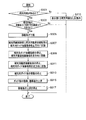
S107の後、操作者が入力部620を操作することによって印刷要求があったとコントローラ部510が判断した場合(S109)、コントローラ部510は、入力枚数判断部540に総用紙数を算出するように指示する。
次に、コントローラ部510は、積載板321上にある用紙一枚あたりの厚さを測定したデータが記憶部550にあるか否かを検索する(S111)。
After S107, when the
Next, the
ここで、データなしと判断された場合には、コントローラ部510は、搬送部200が用紙を一枚給紙するよう搬送制御部570に指示する。これを受けて、搬送制御部570は、ピックアップローラ210等を駆動させる。そして、紙厚センサ420が搬送された用紙の厚さを測定して(S113)、総用紙数算出部525にその厚さの情報を送信する。また、紙厚センサ420は、記憶部550にも用紙の厚さの情報を送信し、記憶部550はその厚さを記憶する。
次に、総用紙数算出部525は、S103の過程において、総用紙数算出部525が算出した総用紙厚と、紙厚センサ420が検出した一枚あたりの厚さで割ることによって、総用紙数を算出する(S115)。
If it is determined that there is no data, the
Next, the total sheet
次に、判定部530は、入力枚数判断部540から送信された印刷が要求された要求数が、総用紙数算出部525が算出した総用紙数よりも多いか否かを判定する(S117)。
ここで、要求数よりも総用紙数のほうが多いと判定された場合(No)、判定部530は、その情報をコントローラ部510に送信し、コントローラ部510は、画像形成制御部560と搬送制御部570とトレイ制御部580に所定の動作を行うよう指示し、画像形成部100は印刷を開始する(S121)。
一方で、要求数よりも総用紙数のほうが少ないと判定された場合(Yes)、判定部530は、その情報をコントローラ部510に送信し、コントローラ部510は、補充用紙制御部590に用紙を補充するように指示する(S119)。尚、用紙を補充する過程についての詳細は、後記する。
また、コントローラ部510は、搬送センサ430から、用紙が搬送されたことを示す信号を受け、記憶部550に記憶された総用紙数から信号分を引いて、総用紙数を更新し(S123)、終了する。
Next, the
If it is determined that the total number of sheets is larger than the requested number (No), the
On the other hand, when it is determined that the total number of sheets is smaller than the requested number (Yes), the
The
(総用紙の厚さを検出方法)
次にS103の積載板321を上昇させる過程について図6を用いて説明する。
コントローラ部510は、トレイ制御部580に、昇降モータ324を駆動させて積載板321を上昇させるように指示する(S201)。
ここで、上限センサ410からの信号がコントローラ部510に送信されると、コントローラ部510はトレイ制御部580に昇降モータ324の回転停止を指示する。また、昇降モータ324における回転数に対応したパルス数を測定し(S203)、総用紙厚算出部520に送信させるようトレイ制御部580に指示する。
(Detection method of total paper thickness)
Next, the process of raising the stacking
The
Here, when the signal from the
次に、総用紙厚算出部520は、上昇した積載板321に用紙が積載されているか否かを判断する。具体的には、予め記憶部550に記憶された用紙がない場合に昇降モータ324から測定されるパルス数と、現在の上昇によって昇降モータ324から測定されたパルス数とに差分があれば、用紙ありと判断される(S205)。
用紙ありと判断した場合(Yes)、総用紙厚算出部520は、その差分に基づいて総用紙厚を求め(S207)、その総用紙厚と用紙ありとする情報をコントローラ部510に送信し(S209)、終了する。
Next, the total sheet
If it is determined that there is a sheet (Yes), the total sheet
一方で、S205の段階で、用紙なしと判断した場合(No)、総用紙厚算出部520は、コントローラ部510を介して補充用紙制御部590に用紙補充するように指示する。
そして、S210の段階においては、前記したS201とS203とS205の段階を経て、積載板321上に用紙があるか否かを判断する(S210)。
ただし、用紙補充部330に用紙がない場合など、依然として、積載板321上に用紙がないと判断した場合(No)、用紙厚算出部がコントローラ部510に用紙なしとする情報を送信する(S212)。
On the other hand, if it is determined in step S205 that there is no paper (No), the total paper
In step S210, it is determined whether there is a sheet on the stacking
However, when it is determined that there is still no paper on the stacking
(補充方法)
次に用紙を補充する過程について、図7と図8を用いて説明する。
まず、用紙を補充するとの指示をうけたコントローラ部510は、図示しない補充用紙センサからの信号を受け、補充用積載板331上に補充用紙があるか否かについて確認をする(S301)。もし、補充用積載板331上に補充用紙がない場合には、コントローラ部510は、表示部610に『補充用紙なし』と表示するよう指示後(S310)、用紙補充を終了する。
コントローラ部510は、補充用積載板331上に補充用紙があると確認できた場合(Yes)、補充用積載板331上にある所定枚数の補充用紙が、積載板321上に補充できる限度以下であるか否かを、積載判断部545によって判断する(S303)。もし、積載板321上に補充できる限度を超えてしまう場合には、用紙補充を終了する。
(Replenishment method)
Next, the process of replenishing paper will be described with reference to FIGS.
First, the
When the
ここで、給紙部320と用紙補充部330は、図8(a)で示すように、積載板321が323によって上昇している状態であるが、積載判断部545が積載可能と判断した場合、コントローラ部510は、トレイ制御部580に積載板321が下降する動作を行うように指示する(S305)。次に、ガイド板322を倒すよう指示し(S305)、図8(b)で示す状態となる。
Here, as shown in FIG. 8A, the
次に、コントローラ部510は、補充用紙制御部590に補充用積載板駆動部332と補充用ガイド板駆動部334を正方向に回動するように指示し(S307)、補充用積載板331と補充用ガイド板333を320側に移動させる。これによって、図8(c)に示すように、補充用積載板331は、積載板321上に位置することとなる。
Next, the
コントローラ部510は、補充用紙板を移動、到達位置センサからの信号を受けて、補充用紙制御部590に補充用ガイド板駆動部334の停止を指示し、補充用積載板駆動部332を逆方向に回動するように指示する(S309)。
これによって、図8(d)に示すように、補充用紙板に積載された補充用紙は、補充用ガイド板333に当接し、補充用積載板331上から積載板321上に落下することとなり、積載板321上に用紙が補充される。
The
As a result, as shown in FIG. 8D, the replenishment paper stacked on the replenishment paper plate comes into contact with the
補充用紙到達板が、補充用紙復帰センサからを所定の位置に戻ったことの信号を受けて、コントローラ部510は、補充用積載板駆動部332を停止と、補充用ガイド板駆動部334を元の位置に復帰するように指示する(S311)。
In response to the signal that the replenishment paper arrival plate has returned to the predetermined position from the replenishment paper return sensor, the
次に、コントローラ部510は、立て板復帰センサにより、所定の位置に復帰したことの信号を受けて、図8(e)に示すように、補充用ガイド板333の移動の停止を指示し(S313)、また、トレイ制御部580には、ガイド板322を回動(復帰)させ、積載板321の上昇するように指示する(S315)。
Next, the
そして、積載板321上に積載されている用紙がピックアッピローラに当接したことを上昇センサからの信号を、コントローラ部510が受けて、トレイ制御部580に積載板321の上昇を停止するように指示し(S317)、終了する。
Then, the
以上、実施形態における画像形成装置1について説明したが、本発明の画像形成装置1によれば、画像形成部100に給紙する用紙が積載される積載板321には、所定枚数以上の用紙が積載されており、用紙を補充する必要がない。また、操作者が用紙を補給するという労力を削減することが可能となる。
The image forming apparatus 1 according to the embodiment has been described above. However, according to the image forming apparatus 1 of the present invention, the stacking
その他、本発明は、実施形態にかかる画像形成装置1に限らず、前記した画像形成装置1に、積載板321上に積載させる動作が完了したことを報知する報知部を加えても良い。
または、総用紙数算出部525が算出した積載板321に積載される用紙の枚数が所定の枚数以下の場合に、用紙補充部330に用紙補充を促す報知部や、総用紙数算出部525によって算出された積載板321に積載される用紙の枚数を報知する報知部を備えても良い。
In addition, the present invention is not limited to the image forming apparatus 1 according to the embodiment, and may include a notification unit that notifies the above-described image forming apparatus 1 that the operation of stacking on the stacking
Alternatively, when the number of sheets stacked on the stacking
1 画像形成装置
100 画像形成部
110a〜110d 画像形成ユニット
120 定着ユニット
200 搬送部
210 ピックアップローラ
220 分離ローラ
230 レジストローラ
240 搬送ベルト
250 排出ローラ
300 用紙収納部
310a 用紙トレイ
315 ケース部材
320 給紙部
321 積載板
322 ガイド板
323 リフトアッププレート
324 昇降モータ
330 用紙補充部
331 補充用積載板
332 補充用積載板駆動部
333 補充用ガイド板
334 補充用ガイド板駆動部
335 第1回動軸
336 第1ベルト
337 コ字部材
338 L字部材
339 第2回動軸
340 第2ベルト
400 センサ部
410 上限センサ
411 下降センサ
420 紙厚センサ
430 搬送センサ
500 制御部
510 コントローラ部
520 総用紙厚算出部
525 総用紙数算出部
530 判定部
540 入力枚数判断部
545 積載判断部
550 記憶部
560 画像形成制御部
570 搬送制御部
580 トレイ制御部
590 補充用紙制御部
610 表示部
620 入力部
DESCRIPTION OF SYMBOLS 1 Image forming apparatus 100 Image forming part 110a-110d
Claims (5)
前記媒体に画像を形成する画像形成部と、
前記積載板に積載された媒体を画像形成部に搬送する搬送部と、
前記積載板に積載された媒体の総枚数を算出する媒体枚数算出部と、
前記媒体トレイ内に位置し、前記積載板上に補充媒体を積載可能な媒体補充部と、
前記媒体枚数算出部が算出した積載板に積載される媒体の枚数が所定の枚数以下の場合に、前記媒体補充部が補充媒体を前記積載板上に積載させる動作を制御する媒体補充部制御部とを備えることを特徴とする画像形成装置。 A media tray for loading and storing media on a loading plate;
An image forming unit that forms an image on the medium;
A transport unit that transports the medium stacked on the stacking plate to an image forming unit;
A medium number calculation unit for calculating the total number of media loaded on the loading plate;
A medium replenishment unit located in the medium tray and capable of loading a replenishment medium on the stacking plate;
A medium replenishment unit control unit that controls the operation of the medium replenishment unit loading a replenishment medium on the stacking plate when the number of media loaded on the loading plate calculated by the medium number calculation unit is equal to or less than a predetermined number An image forming apparatus comprising:
前記所定の枚数は、前記入力部に入力された枚数に応じた画像形成枚数であることを特徴とする請求項1に記載の画像形成装置。 An input unit for inputting the number of image formations desired by the operator is provided.
The image forming apparatus according to claim 1, wherein the predetermined number is an image forming number corresponding to the number input to the input unit.
Priority Applications (1)
| Application Number | Priority Date | Filing Date | Title |
|---|---|---|---|
| JP2008322636A JP2010143714A (en) | 2008-12-18 | 2008-12-18 | Image forming device |
Applications Claiming Priority (1)
| Application Number | Priority Date | Filing Date | Title |
|---|---|---|---|
| JP2008322636A JP2010143714A (en) | 2008-12-18 | 2008-12-18 | Image forming device |
Publications (1)
| Publication Number | Publication Date |
|---|---|
| JP2010143714A true JP2010143714A (en) | 2010-07-01 |
Family
ID=42564540
Family Applications (1)
| Application Number | Title | Priority Date | Filing Date |
|---|---|---|---|
| JP2008322636A Pending JP2010143714A (en) | 2008-12-18 | 2008-12-18 | Image forming device |
Country Status (1)
| Country | Link |
|---|---|
| JP (1) | JP2010143714A (en) |
Cited By (2)
| Publication number | Priority date | Publication date | Assignee | Title |
|---|---|---|---|---|
| JP2012012183A (en) * | 2010-07-01 | 2012-01-19 | Duplo Seiko Corp | Paper feeding system |
| JP2022093580A (en) * | 2017-05-19 | 2022-06-23 | キヤノン株式会社 | Paper feeding device and image formation device |
Citations (7)
| Publication number | Priority date | Publication date | Assignee | Title |
|---|---|---|---|---|
| JPH04292351A (en) * | 1990-10-10 | 1992-10-16 | Fuji Xerox Co Ltd | Printer control device |
| JPH06135640A (en) * | 1992-10-29 | 1994-05-17 | Ricoh Co Ltd | Paper feeding device |
| JPH08227252A (en) * | 1995-02-22 | 1996-09-03 | Canon Inc | Image forming device |
| JPH09202463A (en) * | 1996-01-24 | 1997-08-05 | Ricoh Co Ltd | Paper feed device |
| JP2005179056A (en) * | 2003-11-27 | 2005-07-07 | Duplo Seiko Corp | Paper feeder and its method |
| JP2006076691A (en) * | 2004-09-08 | 2006-03-23 | Canon Inc | Printing device |
| JP2006290606A (en) * | 2005-04-14 | 2006-10-26 | Maruishi Seisakusho:Kk | Paper feeding method and paper feeding device |
-
2008
- 2008-12-18 JP JP2008322636A patent/JP2010143714A/en active Pending
Patent Citations (7)
| Publication number | Priority date | Publication date | Assignee | Title |
|---|---|---|---|---|
| JPH04292351A (en) * | 1990-10-10 | 1992-10-16 | Fuji Xerox Co Ltd | Printer control device |
| JPH06135640A (en) * | 1992-10-29 | 1994-05-17 | Ricoh Co Ltd | Paper feeding device |
| JPH08227252A (en) * | 1995-02-22 | 1996-09-03 | Canon Inc | Image forming device |
| JPH09202463A (en) * | 1996-01-24 | 1997-08-05 | Ricoh Co Ltd | Paper feed device |
| JP2005179056A (en) * | 2003-11-27 | 2005-07-07 | Duplo Seiko Corp | Paper feeder and its method |
| JP2006076691A (en) * | 2004-09-08 | 2006-03-23 | Canon Inc | Printing device |
| JP2006290606A (en) * | 2005-04-14 | 2006-10-26 | Maruishi Seisakusho:Kk | Paper feeding method and paper feeding device |
Cited By (2)
| Publication number | Priority date | Publication date | Assignee | Title |
|---|---|---|---|---|
| JP2012012183A (en) * | 2010-07-01 | 2012-01-19 | Duplo Seiko Corp | Paper feeding system |
| JP2022093580A (en) * | 2017-05-19 | 2022-06-23 | キヤノン株式会社 | Paper feeding device and image formation device |
Similar Documents
| Publication | Publication Date | Title |
|---|---|---|
| US8152159B2 (en) | Sheet feeding device and image forming apparatus including a controlled elevator mechanism | |
| JP5720646B2 (en) | Paper feeding device and image forming apparatus | |
| JP4297912B2 (en) | Paper feeder | |
| JP2009062158A (en) | Sheet feeder and image forming apparatus having the same | |
| KR101749568B1 (en) | Paper supply unit and control method thereof and image forming apparatus for the same | |
| US20080001342A1 (en) | Sheet feeder and image forming apparatus having said sheet feeder | |
| US20060291874A1 (en) | Image forming apparatus having duplex printing capability and paper discharging method thereof | |
| JP4764803B2 (en) | Sheet material stacking amount calculation method, replenishment amount calculation method, and sheet feeding device in sheet feeding device | |
| JP2010143714A (en) | Image forming device | |
| JP2010120709A (en) | Paper feeder and image forming device | |
| JP5322848B2 (en) | Image forming apparatus | |
| JP2009265134A (en) | Image forming apparatus | |
| JP2007091442A (en) | Image forming device | |
| JP2006232531A (en) | Paper sheet feeder, and image forming apparatus | |
| JP2009227374A (en) | Paper feeder and image forming device | |
| JP5058927B2 (en) | Paper feeding device and image forming apparatus having the same | |
| JP2010037034A (en) | Paper feeding device and image forming device with the same | |
| JP2007057649A (en) | Image forming apparatus | |
| JP2007314302A (en) | Image forming device | |
| JP2006232516A (en) | Sheet material carrying device and image forming apparatus | |
| JP7538634B2 (en) | Image forming device | |
| JP2009086489A (en) | Image forming apparatus | |
| JP2009288503A (en) | Image forming apparatus | |
| JP2011046459A (en) | Paper feeder and image forming device | |
| JP2009274826A (en) | Image forming device |
Legal Events
| Date | Code | Title | Description |
|---|---|---|---|
| A711 | Notification of change in applicant |
Free format text: JAPANESE INTERMEDIATE CODE: A712 Effective date: 20110131 |
|
| A621 | Written request for application examination |
Free format text: JAPANESE INTERMEDIATE CODE: A621 Effective date: 20110608 |
|
| A977 | Report on retrieval |
Free format text: JAPANESE INTERMEDIATE CODE: A971007 Effective date: 20120824 |
|
| A131 | Notification of reasons for refusal |
Effective date: 20120828 Free format text: JAPANESE INTERMEDIATE CODE: A131 |
|
| A521 | Written amendment |
Free format text: JAPANESE INTERMEDIATE CODE: A523 Effective date: 20121025 |
|
| A02 | Decision of refusal |
Free format text: JAPANESE INTERMEDIATE CODE: A02 Effective date: 20130528 |