JP2010143699A - Slackened shishiodoshi - Google Patents
Slackened shishiodoshi Download PDFInfo
- Publication number
- JP2010143699A JP2010143699A JP2008321711A JP2008321711A JP2010143699A JP 2010143699 A JP2010143699 A JP 2010143699A JP 2008321711 A JP2008321711 A JP 2008321711A JP 2008321711 A JP2008321711 A JP 2008321711A JP 2010143699 A JP2010143699 A JP 2010143699A
- Authority
- JP
- Japan
- Prior art keywords
- chute
- seesaw
- processing product
- product
- stopper
- Prior art date
- Legal status (The legal status is an assumption and is not a legal conclusion. Google has not performed a legal analysis and makes no representation as to the accuracy of the status listed.)
- Pending
Links
Images


Abstract
Description
本発明は、比較的小さな金属加工製品を、通函やプラスチックケース等に貯める為の、シュートに関するものである。 The present invention relates to a chute for storing a relatively small metal processed product in a box or a plastic case.
工作機械で加工された金属製品は、ロボット等で排出し特定のケースに整列させることもあるが、比較的小さな金属加工製品は1個ずつシュートに落とし、工作機械の外まで転がして、通函やプラスチックケース等に落下させることも多い。この場合は、通函の中に金属加工製品が無造作に貯まっていく。 Metal products processed by machine tools may be ejected by robots and aligned in specific cases, but relatively small metal processed products are dropped one by one on a chute and rolled out of the machine tool. Often dropped into a plastic case. In this case, metal processed products are stored randomly in the box.
シュートの出口の高さは、通函のふちの高さよりも上にあるのが普通で、シュートの出口を通函の中に入れ込むと、金属加工製品が貯まってきた場合、シュートの出口で製品が詰まってしまうからである。
シュートの出口から落下した金属加工製品は通函に少し貯まると製品どうしが衝突する。少しの高さでも落下させているのでその衝撃は激しく、金属加工製品に傷をつける。 When metal processed products dropped from the exit of the chute are stored a little in the box, the products collide with each other. Since it is dropped even at a slight height, the impact is intense and damages the metal processed product.
本発明は、製品の落下による衝撃を緩和させ、且つ、製品が通函の中に貯まってきても詰まらないシーソー式シュートに関するものである。 The present invention relates to a seesaw-type chute that mitigates impact caused by falling of a product and does not clog even if the product is stored in a box.
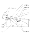
金属製又は樹脂製で半円筒形、又は、コの字形の断面形状を有するシュートにおいて、シーソーの様な動きをする為に支点軸3を設け、支点よりシュート出口側にワークストッパ2を設け、支点よりシュート出口側と反対側にバランスをとる為のバランサー4とシュート角度調整の為のシーソーストッパ5を設ける。このシーソー式シュートを通函9やプラスチックケース等の上に設置する。
In a chute made of metal or resin and having a semi-cylindrical or U-shaped cross section, a
他の機械よりシュートにて排出されてきた金属加工製品8をワークストッパ2とシュート出口の間に落とす。よく落ちる場所にはゴムやスポンジ等のクッション材を貼ると良い。 The metal processed product 8 discharged from the chute from another machine is dropped between the work stopper 2 and the chute outlet. Cushioning material such as rubber or sponge should be put on the place where it falls often.
支点よりシュート出口側の総モーメントをMa、反対側の総モーメントをMb、金属加工製品の重量によるモーメントをMxとすると、数1(A)式及び(B)式を満たす様にバランサー4の重量と位置、及び金属加工製品8の落下位置を調整する。 If the total moment on the chute exit side from the fulcrum is Ma, the total moment on the opposite side is Mb, and the moment due to the weight of the metal processed product is Mx, the weight of the balancer 4 to satisfy the formulas (A) and (B) And the position where the metal processed product 8 is dropped.
すなわち金属加工製品8が、シーソー式シュート1上に無い場合は、水平面に対し、シュートが下に10度程度のゆるやかな傾斜にし、有る場合は水平面に対しシュートが下に40度程度の急な傾斜になる様に設定する。 That is, when the metal processed product 8 is not on the seesaw type chute 1, the chute has a gentle inclination of about 10 degrees below the horizontal plane, and if it exists, the chute is about 40 degrees below the horizontal plane. Set to be inclined.
工作機械より、シュートにて排出されてきた金属加工製品8をシーソー式シュート1上に落とすと、その製品の重力により、ゆっくりと傾斜角度が大きくなりシュート出口側に向かって製品を転がり落とす。 When the metal processed product 8 discharged by the chute from the machine tool is dropped onto the seesaw chute 1, the inclination angle gradually increases due to the gravity of the product, and the product rolls down toward the chute outlet side.
この時、シーソー式シュート1が無い場合のシュートから落下させた金属加工製品8の衝撃に比べ、計り知れないほど衝撃が緩和され金属加工製品に傷を付け難くする。 At this time, compared with the impact of the metal processed product 8 dropped from the chute when the seesaw type chute 1 is not provided, the impact is relieved so much that the metal processed product is hardly damaged.
既に、通函9やプラスチックケース等に、ある程度の量の金属加工製品8が入っている場合でもシーソー式シュート1の出口側先端に設けた傾斜ストッパ6によって貯まった製品に接触し、それ以上、急な傾斜にならない様にした自動可変傾斜機能が特徴であり、シュートの出口で製品が詰まらない。 Even if a certain amount of the metal processed product 8 is already contained in the box 9 or the plastic case, it comes into contact with the product stored by the inclined stopper 6 provided at the front end of the seesaw chute 1 and beyond, It features an automatic variable tilt function that prevents steep tilting, so that products are not clogged at the exit of the chute.
又、本発明のスラックンシオドは、駆動部品(モータ・エアーシリンダ等)が不要な為、非常に容易に設置できる。 In addition, the slack squeeze of the present invention can be installed very easily because no driving parts (motor, air cylinder, etc.) are required.
本発明の実施例を添付図面に基づいて詳細に説明する。 Embodiments of the present invention will be described in detail with reference to the accompanying drawings.
金属製又は、樹脂製で断面形状が、図2の何れかの様なシュートにおいて図1の様に、支点軸3を設け、ここを中心にシーソーの様な天秤運動ができる構造とする。支点軸3よりシュート出口側にワークストッパ2を設け、これよりシュート出口と反対側に金属加工製品8が行かない様にしておく。又、支点軸3は蝶番を利用しても良い。
As shown in FIG. 1, a
支点軸3よりシュート出口と反対側にバランサー4を設け、金属加工製品8が無い時は、シーソー式シュート1がバランサー4側に傾斜する様にする。バランサー4は重量と位置を調整できる様にし、シーソー式シュート1がわずかな力で動作する様にする。
The balancer 4 is provided on the opposite side of the chute outlet from the
すなわち、支点よりシュート出口側の総モーメントをMa、反対のバランサー4側の総モーメントをMb、金属加工製品8の重量によるモーメントをMxとすると、数1(A)式及び(B)式を満たす様に調整する。 That is, when the total moment on the chute outlet side from the fulcrum is Ma, the total moment on the opposite balancer 4 side is Mb, and the moment due to the weight of the metal processed product 8 is Mx, Equations (A) and (B) are satisfied. Adjust as follows.
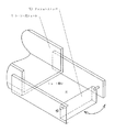
バランサー4の下側にシーソーストッパ5を設け、図3の様に金属加工製品8がシーソー式シュート1の上に無い時でも、シーソー出口側が下方にわずかに傾斜する様に調整する。金属加工製品8の形状にもよるが、この傾斜角は、0度〜15度が望ましい。 A seesaw stopper 5 is provided below the balancer 4 and adjusted so that the seesaw outlet side is slightly inclined downward even when the metal processed product 8 is not on the seesaw chute 1 as shown in FIG. Although depending on the shape of the metal processed product 8, the inclination angle is preferably 0 to 15 degrees.
図3の様に、これを、ベース7を用いて通函9やプラスチックケースの上に設置する。ベース7は通函9の上に固定しても、又は、別のところから固定しても良い。 As shown in FIG. 3, this is installed on the box 9 or the plastic case using the base 7. The base 7 may be fixed on the box 9 or may be fixed from another place.
シーソー式シュート1上で、ワークストッパ2よりシュート出口側に、工作機械等で加工されシュートにて排出されてきた金属加工製品8を落とすと、その重力によりモーメントMxが発生する。そして、シーソー式シュート1上をシュート出口側に転がるので、支点軸3からの距離が長くなる為、Mxは徐々に大きくなる。この作用によりシーソー式シュート1は、どんどん傾斜角を大きくするので、金属加工製品8は、通函9内へ転がり落ちる。この時の衝撃は、通函9の上部から落下させるのより随分緩和されるので、金属加工製品8どうしが衝突して傷を付けることが無くなる。シーソー式シュート1上に、金属加工製品8が無くなると、シーソー式シュート1は自重で元の位置に戻る。
On the seesaw type chute 1, when the metal processed product 8 processed by a machine tool or the like and discharged by the chute is dropped from the work stopper 2 to the chute outlet side, a moment Mx is generated by the gravity. And since it rolls on the seesaw type chute 1 to the chute outlet side, since the distance from the
又、実際に、本発明のスラックンシオドを実験してみると、特に軽い金属加工製品8ではシーソー式シュート1上で縦向きとなり止まってしまう場合もあるが、落下位置から移動して止まるので次の金属加工製品8が来ても衝突すること無くMxは2倍となり、シーソー式シュート1の傾斜が大きくなる為、2個とも転がり、又は滑り落ちる。 Moreover, in actuality, when the slack siood of the present invention is tested, the light metal processed product 8 sometimes stops vertically on the seesaw chute 1 but stops after moving from the dropping position. Even if the metal processed product 8 comes, Mx is doubled without colliding and the inclination of the seesaw chute 1 is increased, so that both of them roll or slide down.
シーソー式シュート1のシュート出口下部にゴム製等の傾斜ストッパ6を設ける。図4の様に通函9内に金属加工製品8が沢山貯まってきた時に接触させて、それ以上、シーソー式シュート1を傾斜させない為の自動可変傾斜機能で、これによってシュート出口で金属加工製品8が詰まるのを防ぐことができる。この傾斜ストッパ6は、シーソー式シュート1の材質が金属加工製品8の材質より軟らかい物であれば、シーソー式シュート1のシュート出口先端が同様の機能を果たすので無くても良い。 An inclined stopper 6 made of rubber or the like is provided at the lower portion of the chute outlet of the seesaw chute 1. As shown in FIG. 4, this is an automatic variable tilting function to prevent the seesaw chute 1 from tilting when a large amount of the metalworked product 8 is stored in the box 9, and the metalworked product at the exit of the chute. 8 can be prevented from clogging. If the material of the seesaw chute 1 is softer than the material of the metal processed product 8, the inclined stopper 6 may be omitted because the tip of the chute outlet of the seesaw chute 1 performs the same function.
本発明のスラックンシオドは、公知である鹿威しや、計測・計量用のシーソー式ホッパーと構造が良く似ているが、第1に鹿威しやシーソー式ホッパーは、液体又は、粉体等の流動性のある物を対象にしているのに対し、本発明のスラックンシオドは、金属加工製品を対象にしている。第2に、基準となる傾斜が、鹿威しやシーソー式ホッパーは、出口と反対側に傾斜させている(反対側に傾斜させないと機能を果たさない)のに対し、本発明のスラックンシオドは、出口と同じ側に緩やかな傾斜をさせている。第3にスラックンシオドのシーソー式シュート1に金属加工製品8が載ると徐々に角度を急に傾斜させる為、転がり又は滑り落ちる速度を減速させることができる。鹿威しやシーソー式ホッパーにはその役目は無い。第4に、図4の様にスラックンシオドのシーソー式シュート1のシュート出口先端は自動可変傾斜できるので、通函9の中に徐々に貯まっていく金属加工製品8の高さに合わせて、シュート出口の高さを変えることができるのを特徴とする。この自動可変傾斜機能があることによってシーソー式シュート1のシュート出口で金属加工製品8が詰まるのを防いでいる。 The slack siood of the present invention is similar in structure to a well-known deer or measurement / weighing seesaw hopper, but first, the deer or seesaw hopper is a liquid or powder or the like. The slack siood of the present invention is intended for metal processed products, while it is intended for fluid objects. Secondly, the standard inclination is that the deer and seesaw type hopper is inclined to the opposite side of the exit (it does not function unless it is inclined to the opposite side), while It has a gentle slope on the same side as the exit. Thirdly, when the metal processed product 8 is placed on the seesaw type chute 1 of the slack-nio-sodo, the angle gradually inclines, so that the rolling or sliding speed can be reduced. Rashiwei and seesaw type hoppers have no role. Fourth, as shown in FIG. 4, the tip of the slat outlet of the slack slashed sword 1 can automatically be tilted so that the chute outlet can be adjusted according to the height of the metal product 8 gradually stored in the box 9. It is characterized in that the height of the can be changed. The automatic variable tilt function prevents the metal processed product 8 from clogging at the chute outlet of the seesaw chute 1.
本発明のスラックンシオドのシーソー式シュートのシュート出口部に、図5の様に金属加工製品8が充分に落とせる穴をあけ、その先端にゴム製やスポンジ製のクッションストッパ10を設ける。 As shown in FIG. 5, a hole through which the metal processed product 8 can be sufficiently dropped is formed at the chute outlet portion of the slack-sienod seesaw chute of the present invention, and a cushion stopper 10 made of rubber or sponge is provided at the tip.
シーソー式シュート1の傾斜角度が急な場合、金属加工製品8は、その慣性力によって穴を飛び越し、クッションストッパ10に当たって跳ね返って、穴から落ちる。このクッションストッパ10によって金属加工製品8の速度は極端に減速される為、金属加工製品8どうしが衝突して傷を付けることが無くなる。 When the inclination angle of the seesaw chute 1 is steep, the metal processed product 8 jumps over the hole due to its inertial force, hits the cushion stopper 10 and bounces down and falls from the hole. Since the speed of the metal processed product 8 is extremely reduced by the cushion stopper 10, the metal processed products 8 do not collide with each other to be damaged.
尚、これを実際に実験してみると、クッションストッパ10が有ると通函9の中で金属加工製品8が不均一に広がる長所がある。無いと1カ所で山形になりやすい。これは、クッションストッパ10によって、金属加工製品8の速度を減速し、力の方向(ベクトル)が不均一になったからである。 When this is actually tested, there is an advantage that the metal processed product 8 spreads unevenly in the box 9 when the cushion stopper 10 is provided. Without it, it tends to be Yamagata in one place. This is because the cushion stopper 10 reduces the speed of the metal processed product 8 and the force direction (vector) becomes uneven.
クッションストッパ10を図6の様に回転式とすると、尚一層、ベクトルを不均一にすることができ、又、傾斜ストッパ6の代わりともなる。 If the cushion stopper 10 is a rotary type as shown in FIG. 6, the vector can be made more uneven, and it can be used in place of the tilt stopper 6.
実施例1でも記した様に、公知である鹿威しや、計測・計量用のシーソー式ホッパーでは、本発明のスラックンシオドとは機能が異なる為、このクッションストッパ10は、役に立たない。

産業界では、工作機械で加工された金属加工製品を排出するのにシュートを用い、通函やプラスチックケースの中に落下させて貯めていくことが多く、金属加工製品どうしが衝突して傷が付き、不良品となってしまう。 In industry, chutes are often used to discharge metal processed products processed by machine tools and dropped into boxes or in plastic cases for storage, and metal processed products collide with each other to cause scratches. It becomes a defective product.
本発明のスラックンシオドは、この衝突エネルギーを緩和でき、傷による不良品を無くすことができる。又、装置が簡単でコンパクト、且つ、無動力な為、設置が非常に容易である。 The slack-niood of the present invention can alleviate this collision energy and eliminate defective products due to scratches. Moreover, since the apparatus is simple, compact, and powerless, installation is very easy.
1 シーソー式シュート
2 ワークストッパ
3 支点軸
4 バランサー
5 シーソーストッパ
6 傾斜ストッパ
7 ベース
8 金属加工製品
9 通函
10 クッションストッパ
DESCRIPTION OF SYMBOLS 1 Seesaw type chute 2
Claims (2)
Priority Applications (1)
| Application Number | Priority Date | Filing Date | Title |
|---|---|---|---|
| JP2008321711A JP2010143699A (en) | 2008-12-18 | 2008-12-18 | Slackened shishiodoshi |
Applications Claiming Priority (1)
| Application Number | Priority Date | Filing Date | Title |
|---|---|---|---|
| JP2008321711A JP2010143699A (en) | 2008-12-18 | 2008-12-18 | Slackened shishiodoshi |
Publications (1)
| Publication Number | Publication Date |
|---|---|
| JP2010143699A true JP2010143699A (en) | 2010-07-01 |
Family
ID=42564528
Family Applications (1)
| Application Number | Title | Priority Date | Filing Date |
|---|---|---|---|
| JP2008321711A Pending JP2010143699A (en) | 2008-12-18 | 2008-12-18 | Slackened shishiodoshi |
Country Status (1)
| Country | Link |
|---|---|
| JP (1) | JP2010143699A (en) |
Cited By (4)
| Publication number | Priority date | Publication date | Assignee | Title |
|---|---|---|---|---|
| JP2013212846A (en) * | 2012-03-30 | 2013-10-17 | Canon Marketing Japan Inc | Single-dose packing system, relay unit |
| CN104773470A (en) * | 2015-03-30 | 2015-07-15 | 宁夏众信机械设备制造有限公司 | Contusion-proof buffer device |
| CN106422304A (en) * | 2015-08-11 | 2017-02-22 | 保利集团澳门有限公司 | Water bucket games, systems, and methods |
| KR102475630B1 (en) * | 2022-08-22 | 2022-12-07 | 김성왕 | Gravity chain conveyor system |
-
2008
- 2008-12-18 JP JP2008321711A patent/JP2010143699A/en active Pending
Cited By (4)
| Publication number | Priority date | Publication date | Assignee | Title |
|---|---|---|---|---|
| JP2013212846A (en) * | 2012-03-30 | 2013-10-17 | Canon Marketing Japan Inc | Single-dose packing system, relay unit |
| CN104773470A (en) * | 2015-03-30 | 2015-07-15 | 宁夏众信机械设备制造有限公司 | Contusion-proof buffer device |
| CN106422304A (en) * | 2015-08-11 | 2017-02-22 | 保利集团澳门有限公司 | Water bucket games, systems, and methods |
| KR102475630B1 (en) * | 2022-08-22 | 2022-12-07 | 김성왕 | Gravity chain conveyor system |
Similar Documents
| Publication | Publication Date | Title |
|---|---|---|
| JP2010143699A (en) | Slackened shishiodoshi | |
| CN204689171U (en) | Article drop buffering mechanism | |
| US7040489B2 (en) | Object orienting and sorting apparatus | |
| JP6218215B2 (en) | Fruit and vegetable supply device | |
| EP2493766B1 (en) | Method and apparatus for the controlled emptying of a transport container filled with articles | |
| CN117509204A (en) | System and method for controlling the discharge of objects in a container by vibration | |
| US20130256090A1 (en) | Gravity chute | |
| WO2006096154A1 (en) | Streamlined pallet handling apparatus and method | |
| CN106076871B (en) | Sphere apparatus for automatically sorting | |
| CN210311061U (en) | Stretching mechanism of PE protection film | |
| JP2006306532A5 (en) | ||
| KR200331979Y1 (en) | Prevention device for inclined accumulation and dropping ore of stacker | |
| RU2007107613A (en) | LOADING DEVICE FOR TAPE AGLOMERATION MACHINE | |
| JP5452094B2 (en) | Dispenser chute damper device | |
| JP2006142221A (en) | Wind separation device | |
| JPH072326A (en) | Buffer chute for powdery and granular material | |
| NL2024205B1 (en) | TRANSMISSION DEVICE AND PROCEDURE | |
| CN220299780U (en) | Ore feeding device | |
| US4674623A (en) | Bucket elevator including means for modifying bucket speed in the loading zone | |
| EP0239175A1 (en) | Device for storing and discharging bulk goods | |
| JP3240046B2 (en) | Stacking device for flat articles | |
| KR101661959B1 (en) | Works delivering system | |
| CN206375318U (en) | A kind of oscillatory type bin | |
| KR101377518B1 (en) | Chute for removing accumulated mineral | |
| NL1035120C2 (en) | DEVICE FOR AGING RELATIVELY LARGE STONES. |