JP2010143612A - Cap member - Google Patents
Cap member Download PDFInfo
- Publication number
- JP2010143612A JP2010143612A JP2008322558A JP2008322558A JP2010143612A JP 2010143612 A JP2010143612 A JP 2010143612A JP 2008322558 A JP2008322558 A JP 2008322558A JP 2008322558 A JP2008322558 A JP 2008322558A JP 2010143612 A JP2010143612 A JP 2010143612A
- Authority
- JP
- Japan
- Prior art keywords
- casing
- ring
- annular
- cap
- cap member
- Prior art date
- Legal status (The legal status is an assumption and is not a legal conclusion. Google has not performed a legal analysis and makes no representation as to the accuracy of the status listed.)
- Pending
Links
Images


Abstract
Description
本発明は、キャップ部材に関し、特に、外周面にOリングが装着されることにより、キャップ部材およびケーシングの内部をOリングによって液密的に保持することができるキャップ部材に関する。 The present invention relates to a cap member, and in particular, to a cap member that can hold the cap member and the inside of a casing in a liquid-tight manner by the O-ring by mounting an O-ring on an outer peripheral surface.
一般に、Oリングを介してケーシングに液密的に装着されるキャップ部材として、例えば、内燃機関を潤滑するオイルに混入した不純物等を濾過するエレメントを交換可能とするエレメント交換型フィルタを備えたキャップ部材が知られている。 In general, as a cap member that is liquid-tightly attached to a casing via an O-ring, for example, a cap having an element exchange type filter that can replace an element that filters impurities mixed in oil that lubricates an internal combustion engine. Members are known.
従来のキャップ部材を備えたエレメント交換型フィルタとしては、図9に示すようなものが知られている(例えば、特許文献1参照)。図9において、筒状のケーシング1は、図示しないエレメントを収納するとともに、図示しない内燃機関のシリンダブロックに固定されており、ケーシング1の内周面には螺旋状に延在する雌ネジ2が形成されている。
As an element exchange type filter provided with the conventional cap member, what is shown in FIG. 9 is known (for example, refer patent document 1). In FIG. 9, a
このケーシング1にはキャップ部材3が装着されるようになっており、このキャップ部材3は、ケーシング1に対して着脱自在となっている。キャップ部材3は、有底筒状に形成されており、外周面に螺旋状の雄ネジ4が形成され、この雄ネジ4が雌ネジ2に螺合されることにより、キャップ部材3がケーシング1に締結される。
A
図10に示すように、キャップ部材3の外周面にはOリング5が嵌合されるようになっており、このOリング5は、キャップ部材3の底部側に設けられた環状凸部6と雄ネジ4の終端側(キャップ部材3の底部側)の環状ネジ部4aによって挟まれる環状溝7に嵌合されている。
As shown in FIG. 10, an O-
また、ケーシング1にはドレン溝8が形成されており、このドレン溝8は、雌ネジ2の軸線方向と平行に延在している。また、キャップ部材3にはドレン溝9が形成されており、このドレン溝9は、雄ネジ4の回転軸に対して軸対称となる周方向に等間隔で設けられ、雄ネジ4の回転軸方向に平行な所定回転位置でドレン溝8と合致してドレン連通を構成するようになっている。
Further, a
このような構成を有するエレメント交換型フィルタにあっては、エレメントを交換する場合に、ケーシング1に対してキャップ部材3を緩めてOリング5によるケーシング1とキャップ部材3の液密状態を解除した際に、所定回転位置でドレン溝8と一方のドレン溝9とを互いに合致させて連通させることによって、ケーシング1とキャップ部材3の内部に貯留されているオイルを外部に排出するようにしている。
In the element exchange type filter having such a configuration, when replacing the element, the
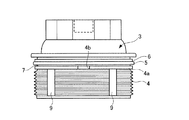
ところで、Oリング5の交換時に、環状溝7にOリング5を容易に着脱することができるようにするために、環状ネジ部4aに作業者の指が入る程度の大きさの切欠き部4bを形成し、環状溝7に挿入されるOリング5が切欠き部4bを通して指で摘めることができるようにすることが考えられる。
しかしながら、このような従来のエレメント交換型フィルタのキャップ部材3にあっては、環状ネジ部4aに作業者の指が入る程度の大きさの切欠き部4bが形成されているため、作業効率を向上させる観点からインパクトレンチ等の回転締結工具によってキャップ部材3をケーシング1に締結する際に、図11に示すように、Oリング5がケーシング1の内周面とキャップ部材3の外周面に挟圧されて環状溝7内で撓んでしまい、Oリング5の一部が切欠き部4bに挟み込まれてしまうことがあった。
However, in the
このため、Oリング5が損傷したり、最悪の場合には切断されてしまい、ケーシング1およびキャップ部材3の内部のシール性能が低下してしまうおそれがあった。
For this reason, the O-
本発明は、上述のような従来の問題を解決するためになされたもので、Oリングが切欠き部に挟み込まれてしまうのを防止することができ、Oリングの損傷や切断を防止して、キャップ本体およびケーシングの内部のシール性能が低下するのを防止することができるキャップ部材を提供することを目的とする。 The present invention has been made to solve the above-described conventional problems, and can prevent the O-ring from being caught in the notch, and can prevent the O-ring from being damaged or cut. An object of the present invention is to provide a cap member that can prevent the sealing performance inside the cap body and the casing from deteriorating.
本発明に係るキャップ部材は、上記目的を達成するため、(1)有底筒状のキャップ本体を有するとともに、前記キャップ本体の外周面の開口側から前記底部側に向かって螺旋状に延在する第1のネジ部がケーシングの内周面に形成された螺旋状の第2のネジ部に螺合することにより、前記キャップ本体が前記ケーシングに着脱自在に設けられ、前記キャップ本体の底部側の前記第1のネジ部の端部に位置する環状ネジ部および前記環状ネジ部から底部側に位置する環状凸部の間に挟み込まれるように、前記キャップ本体の外周面にOリングを嵌合自在なキャップ部材において、前記環状ネジ部の周方向の所定箇所に形成された切欠き部と、前記切欠き部を挟んで前記環状ネジ部に形成され、前記環状ネジ部から前記環状凸部に向かって突出する一対の突起部とを設け、前記キャップ本体が前記ケーシングに装着されたときに、前記キャップ本体および前記ケーシングの内部を前記Oリングによって液密状態に保持するものから構成されている。 In order to achieve the above object, the cap member according to the present invention has (1) a bottomed cylindrical cap body, and spirally extends from the opening side of the outer peripheral surface of the cap body toward the bottom side. The cap main body is detachably provided on the casing by the first screw portion that engages with the spiral second screw portion formed on the inner peripheral surface of the casing, and the bottom side of the cap main body An O-ring is fitted to the outer peripheral surface of the cap body so as to be sandwiched between an annular screw portion located at an end of the first screw portion and an annular convex portion located on the bottom side from the annular screw portion. In the free cap member, a notch portion formed at a predetermined position in the circumferential direction of the annular screw portion, and the annular screw portion sandwiched between the notch portions, and the annular screw portion to the annular convex portion. Protruding toward That provided a pair of projections, when the cap body is mounted on the casing, and a thing that holds the inside of the cap body and the casing in a liquid-tight state by the O-ring.
この構成により、環状ネジ部の周方向の所定箇所に形成された切欠き部と、切欠き部を挟んで環状ネジ部に形成され、環状ネジ部から環状凸部に向かって突出する一対の突起部とを有するので、作業効率を向上させるために、インパクトレンチ等の回転締結工具によってキャップ本体をケーシングに締結する際に、Oリングがケーシングの内周面とキャップ本体の外周面に挟圧されて環状ネジと環状凸部との間で撓んでしまった場合に、Oリングが切欠き部に挟み込まれるようにするには、Oリングを突起部の厚み分だけさらに変形させる必要がある。 With this configuration, a notch portion formed at a predetermined position in the circumferential direction of the annular screw portion, and a pair of protrusions that are formed on the annular screw portion with the notch portion interposed therebetween and project from the annular screw portion toward the annular convex portion When the cap body is fastened to the casing with a rotary fastening tool such as an impact wrench, the O-ring is sandwiched between the inner peripheral surface of the casing and the outer peripheral surface of the cap main body. When the O-ring is bent between the annular screw and the annular convex portion, the O-ring needs to be further deformed by the thickness of the protrusion in order to be sandwiched between the notches.
換言すれば、Oリングを突起部の厚み分だけさらに変形させなければ、Oリングが切欠き部に挟み込まれないようにすることができるので、キャップ本体をケーシングに締結する際にOリングが撓んだ場合であっても、Oリングが切欠き部に挟み込まれるのを防止することができる。 In other words, unless the O-ring is further deformed by the thickness of the protrusion, it is possible to prevent the O-ring from being caught in the notch, so that the O-ring is bent when the cap body is fastened to the casing. Even in such a case, the O-ring can be prevented from being caught in the notch.
この結果、Oリングが損傷したり、切断されてしまうのを防止することができ、ケーシングおよびキャップ本体の内部のシール性能が低下してしまうのを防止することができる。 As a result, the O-ring can be prevented from being damaged or cut, and the sealing performance inside the casing and the cap body can be prevented from being deteriorated.
本発明によれば、Oリングが切欠き部に挟み込まれてしまうのを防止することができ、Oリングの損傷や切断を防止して、キャップ本体およびケーシングの内部のシール性能が低下するのを防止することができるキャップ部材を提供することができる。 According to the present invention, the O-ring can be prevented from being caught in the notch, the O-ring can be prevented from being damaged or cut, and the sealing performance inside the cap body and the casing can be reduced. A cap member that can be prevented can be provided.
以下、本発明に係るキャップ部材の実施の形態について、図面を用いて説明する。
図1〜図8は、本発明に係るキャップ部材の一実施の形態を示す図であり、キャップ部材をエレメント交換型フィルタのキャップ部材に適用した例を示している。
Hereinafter, embodiments of a cap member according to the present invention will be described with reference to the drawings.
FIGS. 1-8 is a figure which shows one Embodiment of the cap member based on this invention, and has shown the example which applied the cap member to the cap member of an element exchange type filter.
まず、構成を説明する。
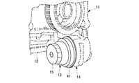
図1において、内燃機関11のシリンダブロック12の下端部にはエレメント交換型フィルタ13が設けられており、このエレメント交換型フィルタ13は、シリンダブロック12の下端部に一体的に固定されたケーシング14と、このケーシング14に対して着脱可能に装着されるキャップ部材15とを備えている。
First, the configuration will be described.
In FIG. 1, an element
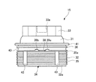
図2は、エレメント交換型フィルタ13の断面図である。エレメント交換型フィルタ13は、ケーシング14およびキャップ部材15に加えて、押え板16、ナット部材17およびフィルタエレメント18を含んで構成されている。
FIG. 2 is a cross-sectional view of the element
内燃機関11から送られてくるオイルは、入口部19からエレメント交換型フィルタ13の内部に流入する。オイルはケーシング14および押え板16に設けられた貫通孔20、21を通過した後に、フィルタエレメント18により濾過された後、中央空間22から接続管23を通って、再び内燃機関11に送り出されるようになっている。
The oil sent from the
内燃機関11のシリンダブロック12には、エレメント交換型フィルタ13を固定するためのブラケット24が設けられており、このブラケット24の上部端面24aは、エレメント交換型フィルタ13を設置するための取付け座となっている。
The
また、ブラケット24は、オイルをシリンダブロック12から導入するための入口部19と、フィルタエレメント18によって濾過されたオイルをシリンダブロック12に送出するための出口部25とを備えている。ブラケット24のオイルの出口部25には雌ネジが加工されており、この雌ネジに接続管23の一端の雄ネジが螺合されることにより、接続管23がブラケット24に締め付け固定されている。
The
また、ケーシング14の下部端面14aは、ブラケット24の上部端面24aに当接しており、ケーシング14は、ブラケット24の所定位置に配置されている。
The
ケーシング14は、筒状に形成されており、ブラケット24の上部端面24aの近傍が円筒形状であるため、ケーシング14がブラケット24に配置されると、ケーシング14とブラケット24の円筒形状が中心軸を共通にして接続された構造となる。
The
押え板16の中央には穴部16aが形成されており、この穴部16aの内周面には雌ネジが形成され、この雄ネジに接続管23の上端に形成された雄ネジに螺合されるようになっている。これにより、円盤形状の押え板16の周縁である押圧部16bがケーシング14の底面14bをブラケット24方向に押え付けることで、ケーシング14がブラケット24に固定される。
A hole 16a is formed in the center of the
また、ナット部材17は、筒状に形成されており、ナット部材17の穴部17aに形成された雌ネジが、接続管23の上端の雄ネジに締め付けられることにより、ナット部材17の下面17bが押え板16の上面16cを下方に押え付けることで、押え板16のネジ締結の緩みが防止されるようになっている。
Further, the nut member 17 is formed in a cylindrical shape, and the
フィルタエレメント18は、濾紙を折曲げて円筒状に形成されたものから構成されており、フィルタエレメント18はケーシング14内に取付けられるようになっている。
The
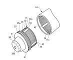
キャップ部材15は、底部31、底部31と一体的に設けられた筒状部32、底部31から上方に突出し、作業者によって把持される把持部33とを備えた有底筒状のキャップ本体34を備えている。
The
また、キャップ本体34の底部31の背面には下方に突出する突出部31aが形成されており、ケーシング14内に取付けられたフィルタエレメント18の上下開放端から突出部31aおよびナット部材17が挿通されることで、フィルタエレメント18がケーシング14内に固定される。
Further, a projecting
図2、図3に示すように、ケーシング14の内周面の開口端側には第2のネジ部としての雌ネジ26が形成されており、この雌ネジ26は、ケーシング14の周方向に螺旋状に延在している。
As shown in FIGS. 2 and 3, a
また、キャップ本体34の筒状部32の外周面には第1のネジ部としての雄ネジ35が形成されており、この雄ネジ35は、筒状部32の周方向に螺旋状に延在している。
A
キャップ本体34は、ケーシング14に着脱自在になっており、雌ネジ26と雄ネジ35が螺合されることにより、キャップ本体34がケーシング14に締結される。また、キャップ本体34の把持部33には嵌合穴33aが形成されており、この嵌合穴33aにはインパクトレンチ等の回転締結工具の回転部の先端が嵌合されるようになっている。
The cap
また、図4に示すように、雄ネジ35は、筒状部32の開口32a側から底部31側に向かって螺旋状に形成されており、雌ネジ26に雄ネジ35が螺合して筒状部32の開口32aがケーシング14に最大限押し込まれたときに、雄ネジ35の端部は、筒状部32の底部31側の雄ネジ35の端部に位置する環状ネジ部35aに位置するようになっている。
As shown in FIG. 4, the
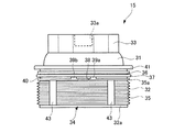
また、環状ネジ部35aに対して底部31側には環状凸部36が設けられており、図5に示すように、環状ネジ部35aおよび環状凸部36の間に挟み込まれるように筒状部32の外周面にOリング37が嵌合されるようになっている。
本実施の形態では、環状ネジ部35a、環状凸部36および筒状部32によって囲まれる環状溝40にOリング37が着脱自在となっている。
Further, an annular
In the present embodiment, an O-
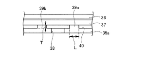
また、図4〜図6に示すように、環状ネジ部35aの周方向の所定箇所に切欠き部38が形成されており、この切欠き部38は、作業者が環状溝40に対してOリング37を着脱する際に、Oリング37を指で摘めるように環状溝40に指が入る程度の大きさに形成されている。
As shown in FIGS. 4 to 6, a
また、環状ネジ部35aには、一対の突起部39a、39bが形成されており、この突起部39a、39bは、切欠き部38を挟んで対向し、環状ネジ部35aから環状凸部36に向かって突出している。
The
図6に示すように、この突起部39a、39bの板厚Tは、環状ネジ部35aの板厚と同等若しくは、それ以下に設定されており、突起部39a、39bの長さは、5mm〜10mmの範囲に設定されている。
As shown in FIG. 6, the plate thickness T of the
また、環状凸部36に対して筒状部32の底部31側にはフランジ部41が形成されており、このフランジ部41は、ケーシング14にキャップ本体34を装着したときに、ケーシング14の開口端14cに当接して、ケーシング14内に取付けられたフィルタエレメント18の上部開放端から突出部31aが適正な位置で挿通されるようにキャップ本体34をケーシング14に対して位置決めするようになっている。
Further, a
また、ケーシング14に対してキャップ本体34を装着したときに、Oリング37がケーシング14とキャップ本体34の間に介装されることにより、キャップ本体34およびケーシング14の内部が液密状態に保持される。
Further, when the cap
また、図3に示すように、ケーシング14の内周面にはドレン溝部42が形成されており、このドレン溝部42は、ケーシング14の軸線方向(キャップ本体34の回転軸線)と同方向に延在している。
Further, as shown in FIG. 3, a
また、図3〜図5に示すように、キャップ本体34の筒状部32の外周面にはドレン溝43が形成されており、このドレン溝43は、キャップ本体34の回転軸線と平行に延在している。このドレン溝43は、例えば、筒状部32の円周方向に等間隔で4個形成されており、ケーシング14に対してキャップ本体34を緩めることにより、Oリング37によってケーシング14およびキャップ本体34の液密状態を解除した際に、ドレン溝43が所定回転位置でドレン溝42と合致するようになっている。
As shown in FIGS. 3 to 5, a
そして、キャップ本体34の所定回転位置でドレン溝42とドレン溝43とが合致したときに、ケーシング14およびキャップ本体34の間のオイルがドレン溝42、43によって画成されるドレン通路から外部に排出されるようになっている。
When the
このような構成を有するエレメント交換型フィルタ13にあっては、Oリング37の交換時に、環状溝40からOリング37を取り外す必要がある。このとき、作業者は、切欠き部38を通してOリング37を摘むことにより、環状溝40からOリング37を容易に取り外すことができる。
In the element
次いで、環状溝40にOリング37を装着した後にキャップ本体34をケーシング14に装着する。このとき、嵌合穴33aにインパクトレンチ等の回転締結工具の回転部の先端を嵌合し、回転部を高速回転させることにより、キャップ本体34を高速回転させることにより、キャップ本体34をケーシング14に取付けることができ、キャップ本体34の取付け作業の作業性を向上させることができる。
Next, after the O-
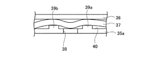
このとき、雌ネジ26に雄ネジ35が螺合することにより、キャップ本体34の筒状部32にケーシング14に高速回転で押し込まれていくため、Oリング37がケーシング14の内周面と筒状部32の外周面に挟圧されて環状溝40内で撓んでしまい、Oリング37の切欠き部38に挟み込まれてしまうおそれがある。
At this time, since the
本実施の形態では、環状ネジ部35aの周方向の所定箇所に形成された切欠き部38を挟んで環状ネジ部35aに形成され、環状ネジ部35aから環状凸部36に向かって突出する一対の突起部39a、39bを設けたので、上述したように作業効率を向上させるために、インパクトレンチ等の回転締結工具によってキャップ本体34をケーシング14に締結する際に、Oリング37がケーシング14の内周面と筒状部32の外周面に挟圧されて環状ネジ部35aと環状凸部36との間で撓んでしまった場合に、Oリング37が切欠き部38に挟み込まれるようにするには、Oリング37を突起部39a、39bの厚み分だけさらに変形させる必要がある。
In the present embodiment, a pair of
換言すれば、Oリング37を突起部39a、39bの厚み分だけさらに変形させなければ、Oリング37が切欠き部38に挟み込まれないようにすることができるので、図7に示すように、キャップ本体34をケーシング14に締結する際にOリング37が撓んだ場合であっても、Oリング37が切欠き部38に挟み込まれるのを防止することができる。
In other words, if the O-
この結果、Oリング37が損傷したり、切断されてしまうのを防止することができ、ケーシング14およびキャップ本体34の内部のシール性能が低下してしまうのを防止することができる。
As a result, the O-
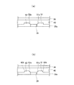
なお、本実施の形態では、図6に示すように、突起部39a、39bの突出端を平面状にしているが、図8(a)に示すように、切欠き部38に位置する突起部51、52にテーパ部51a、52aを設けてもよい。
In the present embodiment, as shown in FIG. 6, the projecting ends of the projecting
このようにすれば、キャップ本体34の装着時に、突起部51、52の切欠き部38側の角部を無くすことができ、Oリング37が切欠き部38側に撓んだ場合に、Oリング37がテーパ部51a、52aに当接させて、Oリング37が損傷するのを防止することができる。
In this way, when the cap
また、図8(b)に示すように、突起部61、62の長さ方向(Oリング37の延在方向)の両端部にテーパ部61a、61b、62a、62bを設けてもよい。
このようにすれば、突起部61、62に角部を無くすことができるため、キャップ本体34の装着時にOリング37が切欠き部38側に撓んだ場合に、Oリング37をテーパ部61a、61b、62a、62bに当接させて、Oリング37が損傷するのを防止することができる。
Moreover, as shown in FIG.8 (b), you may provide
In this way, since the corner portions of the
なお、図8(a)、(b)においては、テーパ部51a、52aを除いた突起部51、52の突出端の長さと、テーパ部61a、61b、62a、62bを除いた突起部61、62の突出端の長さとが、それぞれ5mm〜10mmの範囲に設定されている。
8A and 8B, the lengths of the protruding ends of the protruding
また、本実施の形態では、環状凸部を、フランジ部41と環状ネジ部35aの間に設けられた環状凸部36から構成しているが、フランジ部41から構成してもよい。この場合には、環状凸部36を廃止して環状ネジ部35aをフランジ部41に近接させることにより、環状ネジ部35aおよびフランジ部41の間に挟み込まれるように筒状部32の外周面にOリング37を嵌合すればよい。
また、本実施の形態では、キャップ部材15をエレメント交換型フィルタ13に適用しているが、これに限らず、ケーシングとしてのリザーバタンクに着脱されるキャップ部材等に適用してもよい。要は、キャップ部材およびケーシングの内部をOリングによって液密状態に保持できるものであれば、どのようなキャップ部材にも適用することができる。
Moreover, in this Embodiment, although the cyclic | annular convex part is comprised from the annular
Further, in the present embodiment, the
また、今回開示された実施の形態は、全ての点で例示であってこの実施の形態に制限されるものではない。本発明の範囲は、上記した実施の形態のみの説明ではなくて特許請求の範囲によって示され、特許請求の範囲と均等の意味および範囲内での全ての変更が含まれることが意図される。 The embodiment disclosed this time is illustrative in all respects and is not limited to this embodiment. The scope of the present invention is shown not by the above description of the embodiments but by the scope of claims for patent, and is intended to include all modifications within the meaning and scope equivalent to the scope of claims for patent.
以上のように、本発明に係るキャップ部材は、Oリングが切欠き部に挟み込まれてしまうのを防止することができ、Oリングの損傷や切断を防止して、キャップ本体およびケーシングの内部のシール性能が低下するのを防止することができるという効果を有し、外周面にOリングが装着されることにより、キャップ部材およびケーシングの内部をOリングによって液密的に保持することができるキャップ部材等として有用である。 As described above, the cap member according to the present invention can prevent the O-ring from being caught in the notch, and can prevent the O-ring from being damaged or cut, so that the inside of the cap main body and the casing can be prevented. Cap that has an effect of preventing the sealing performance from being lowered, and the O-ring is attached to the outer peripheral surface, whereby the cap member and the inside of the casing can be liquid-tightly held by the O-ring. It is useful as a member.
14 ケーシング
15 キャップ部材
26 雌ネジ(第2のネジ部)
34 キャップ本体
35 雄ネジ(第1のネジ部)
35a 環状ネジ部
36 環状凸部
37 Oリング
38 切欠き部
39a、39b 突起部
51、52 突起部
61、62 突起部
14
34
35a
Claims (1)
前記キャップ本体の底部側の前記第1のネジ部の端部に位置する環状ネジ部および前記環状ネジ部から前記底部側に位置する環状凸部の間に挟み込まれるように、前記キャップ本体の外周面にOリングを嵌合自在なキャップ部材において、
前記環状ネジ部の周方向の所定箇所に形成された切欠き部と、前記切欠き部を挟んで前記環状ネジ部に形成され、前記環状ネジ部から前記環状凸部に向かって突出する一対の突起部とを設け、
前記キャップ本体が前記ケーシングに装着されたときに、前記キャップ本体および前記ケーシングの内部を前記Oリングによって液密状態に保持することを特徴とするキャップ部材。 A cap body having a bottomed cylindrical shape in which a first screw portion extending spirally from the opening side of the outer peripheral surface toward the bottom side is formed, and the first screw portion is formed on the inner peripheral surface of the casing; The cap main body is detachably provided on the casing by being screwed into the formed spiral second screw portion,
The outer periphery of the cap body so as to be sandwiched between an annular screw part located at an end of the first screw part on the bottom side of the cap body and an annular convex part located on the bottom side from the annular screw part In the cap member that can fit the O-ring on the surface,
A pair of notches formed at predetermined locations in the circumferential direction of the annular threaded portion and a pair of protrusions formed on the annular threaded portion with the notched portion sandwiched therebetween and projecting from the annular threaded portion toward the annular convex portion With a protrusion,
A cap member, wherein the cap body and the inside of the casing are held in a liquid-tight state by the O-ring when the cap body is mounted on the casing.
Priority Applications (1)
| Application Number | Priority Date | Filing Date | Title |
|---|---|---|---|
| JP2008322558A JP2010143612A (en) | 2008-12-18 | 2008-12-18 | Cap member |
Applications Claiming Priority (1)
| Application Number | Priority Date | Filing Date | Title |
|---|---|---|---|
| JP2008322558A JP2010143612A (en) | 2008-12-18 | 2008-12-18 | Cap member |
Publications (1)
| Publication Number | Publication Date |
|---|---|
| JP2010143612A true JP2010143612A (en) | 2010-07-01 |
Family
ID=42564454
Family Applications (1)
| Application Number | Title | Priority Date | Filing Date |
|---|---|---|---|
| JP2008322558A Pending JP2010143612A (en) | 2008-12-18 | 2008-12-18 | Cap member |
Country Status (1)
| Country | Link |
|---|---|
| JP (1) | JP2010143612A (en) |
Cited By (2)
| Publication number | Priority date | Publication date | Assignee | Title |
|---|---|---|---|---|
| JP2013060824A (en) * | 2011-09-12 | 2013-04-04 | Toyota Motor Corp | Oil filter |
| JP2018145900A (en) * | 2017-03-07 | 2018-09-20 | 本田技研工業株式会社 | Oil filter structure of internal combustion engine |
-
2008
- 2008-12-18 JP JP2008322558A patent/JP2010143612A/en active Pending
Cited By (2)
| Publication number | Priority date | Publication date | Assignee | Title |
|---|---|---|---|---|
| JP2013060824A (en) * | 2011-09-12 | 2013-04-04 | Toyota Motor Corp | Oil filter |
| JP2018145900A (en) * | 2017-03-07 | 2018-09-20 | 本田技研工業株式会社 | Oil filter structure of internal combustion engine |
Similar Documents
| Publication | Publication Date | Title |
|---|---|---|
| US9849413B2 (en) | Upper end cap for filter | |
| US7695618B2 (en) | Filter cartridge and mounting system therefor having foolproofing means | |
| RU2615740C2 (en) | Cutting tool with internal fluid supply system | |
| US9248393B2 (en) | Cup-shaped housing, device for separating liquid from air, and method for mounting the cup-shaped housing on a nipple | |
| JP6495960B2 (en) | Filter device | |
| JP2008255917A (en) | Suction filter, fuel pump device, and fuel supply device | |
| US11351484B2 (en) | Spin-on filter for suction-side and pressure-side applications in filtration systems | |
| JP2010143612A (en) | Cap member | |
| JP4831055B2 (en) | Drain mechanism of fluid filter | |
| KR20130002819U (en) | Tubing conjunction structuer for water purifying filter | |
| KR102521405B1 (en) | A spin-on fluid treatment device and method | |
| US20150273371A1 (en) | Filter assembly | |
| JP2006082010A (en) | Fluid filter | |
| JP7357352B2 (en) | Fitting with built-in filter | |
| CN212491894U (en) | Filter cartridge with cartridge insert | |
| CN211734018U (en) | Stack filter core structure | |
| KR101180928B1 (en) | A Fuel Tank of Air Filter For Vehicles | |
| CN211116351U (en) | Filter and engine assembly | |
| CN220609344U (en) | Filter element assembly and egg liquid filter | |
| JP5668652B2 (en) | Oil filter | |
| CN214838574U (en) | Water inlet valve for washing machine | |
| US11331602B2 (en) | Fuel filter with rotatable sleeve | |
| CN210977734U (en) | Detachable fuel filter | |
| JPH074810U (en) | Filter | |
| KR200307504Y1 (en) | a protection cap-tipped filter for a water purifier |