JP2010143584A - Refueling nozzle, refueling nozzle hook, and refueling apparatus - Google Patents
Refueling nozzle, refueling nozzle hook, and refueling apparatus Download PDFInfo
- Publication number
- JP2010143584A JP2010143584A JP2008319120A JP2008319120A JP2010143584A JP 2010143584 A JP2010143584 A JP 2010143584A JP 2008319120 A JP2008319120 A JP 2008319120A JP 2008319120 A JP2008319120 A JP 2008319120A JP 2010143584 A JP2010143584 A JP 2010143584A
- Authority
- JP
- Japan
- Prior art keywords
- nozzle
- oil supply
- supply nozzle
- hook
- locking portion
- Prior art date
- Legal status (The legal status is an assumption and is not a legal conclusion. Google has not performed a legal analysis and makes no representation as to the accuracy of the status listed.)
- Granted
Links
Images

Landscapes
- Loading And Unloading Of Fuel Tanks Or Ships (AREA)
Abstract
【課題】給油ノズルの落下を効果的に防止し得る給油ノズル、給油ノズル掛け及び給油装置を提供する。
【解決手段】本体部2と、本体部2の一端に設けられたノズル部3と、本体部2から突出した弁開レバー5を操作するため、本体部2の他端に設けられた握り部4と、弁開レバー5を囲繞するレバーガード6とを備え、給油ノズル掛け10に収納される給油ノズル1であって、レバーガード6に、弁開レバー5の反対側に突出し、給油ノズル掛け10に突設された突出部(係止部)12に係止されるローラ(係止部)7を備える給油ノズル1。ローラ7に代えて、ピン又は突出部を用いることもできる。ローラ7等は、突出部12に不安定な状態で載置された状態となり難く、給油ノズル1を給油ノズル掛け10に収納する際に、給油ノズル1のローラ7等を給油ノズル掛け10の突出部12に接触させ易く、給油ノズル1を正規の位置に収納したことを容易に認識することができる。
【選択図】図1An oil supply nozzle, an oil supply nozzle hook, and an oil supply device capable of effectively preventing the oil supply nozzle from falling are provided.
A grip portion provided at the other end of the main body portion 2 for operating a main body portion 2, a nozzle portion 3 provided at one end of the main body portion 2, and a valve opening lever 5 protruding from the main body portion 2. 4 and a lever guard 6 that surrounds the valve opening lever 5, and is an oil supply nozzle 1 that is accommodated in the oil supply nozzle hook 10, and projects to the lever guard 6 on the opposite side of the valve opening lever 5. An oil supply nozzle 1 including a roller (locking portion) 7 locked to a protruding portion (locking portion) 12 protruding from 10. Instead of the roller 7, a pin or a protrusion can be used. The roller 7 or the like is unlikely to be placed in an unstable state on the protruding portion 12, and the roller 7 or the like of the oil supply nozzle 1 protrudes from the oil supply nozzle hook 10 when the oil supply nozzle 1 is stored in the oil supply nozzle hook 10. It is easy to make it contact with the part 12, and it can recognize easily that the oil supply nozzle 1 was accommodated in the regular position.
[Selection] Figure 1
Description
本発明は、自動車等の車両へガソリン等の燃料油を給油するために用いられる給油ノズル、該給油ノズルを収納するための給油ノズル掛け及び給油装置に関する。 The present invention relates to an oil supply nozzle used for supplying fuel oil such as gasoline to a vehicle such as an automobile, an oil supply nozzle hook for storing the fuel supply nozzle, and an oil supply device.
近年、人件費削減等のため、給油作業、窓拭き等のサービス作業、及び給油料金の精算作業を顧客自身が行うセルフサービス方式の給油所が急増している。このようなセルフサービス方式の給油所で用いられている給油装置は、顧客自身が給油ノズルを給油ノズル掛けから取り外し、車両の給油口へ給油ノズルの先端部を挿入して給油し、給油後、給油ノズルを給油ノズル掛けに戻す。 In recent years, in order to reduce labor costs, the number of self-service type gas stations where service work such as refueling work, window cleaning, etc., and reimbursement of refueling charges is increasing. The refueling device used in such a self-service fueling station, the customer himself removes the refueling nozzle from the refueling nozzle hook, inserts the front end of the refueling nozzle into the refueling port of the vehicle, and refuels. Return the oil nozzle to the oil nozzle hook.
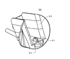
従来用いられている給油ノズルは、例えば図7に示すように、本体部52と、ノズル部53と、弁開レバー55を操作するための握り部54と、弁開レバー55を囲繞するレバーガード56等で構成される。
For example, as shown in FIG. 7, a conventionally used oil supply nozzle includes a
一方、従来用いられている給油ノズル掛けは、例えば図8に示すように、給油装置(不図示)の本体に装着され、上記給油ノズル51が載置される受け部61と、受け部61の入口近傍に突設された突出部(係止部)62と、給油ノズル51全体を収納する収納箱63とで構成される。
On the other hand, as shown in FIG. 8, for example, a conventionally used oil supply nozzle hook is mounted on a main body of an oil supply device (not shown), and a receiving
上記構成を有する給油ノズル51を給油ノズル掛け60に収納する際には、給油ノズル51による給油完了後、人差し指を弁開レバー55から離し、給油ノズル51を把持した状態でノズル部53を給油ノズル掛け60に向けながら、ノズル部53を給油ノズル掛け60の収納部63の奥まで収納する。その後、図7(b)に示すように、給油ノズル51のレバーガード56を給油ノズル掛け60の受け部61に載置する。この際、レバーガード56のピン57を給油ノズル掛け60の突出部62の奥側に位置させることにより、給油ノズル51の給油ノズル掛け60への収納が終了する。
When the refueling
しかし、上記従来の給油ノズル51及び給油ノズル掛け60では、給油ノズル51を給油ノズル掛け60に収納した際に、給油ノズル51のピン57と、給油ノズル掛け60の受け部61に突設した突出部62との係合が不十分であると、給油ノズル51が次に給油しようとする顧客の足下に落下して怪我をさせたり、付近の車両を損傷したり、給油ノズル51の破損に繋がる虞があった。
However, in the conventional
そこで、本発明は、上記従来の給油ノズル等における問題点に鑑みてなされたものであって、給油ノズルを給油ノズル掛けに収納する際に、両者の係合を容易に行うことができ、給油ノズルの落下を効果的に防止し得る給油ノズル、給油ノズル掛け及び給油装置を提供することを目的とする。 Therefore, the present invention has been made in view of the problems in the conventional oiling nozzles and the like, and when the oiling nozzle is housed in the oiling nozzle hook, both can be easily engaged, An object of the present invention is to provide an oil supply nozzle, an oil supply nozzle hook, and an oil supply device that can effectively prevent the nozzle from falling.
上記目的を達成するため、本発明は、本体部と、該本体部の一端に設けられたノズル部と、前記本体部から突出した弁開レバーを操作するため、前記本体部の他端に設けられた握り部と、前記弁開レバーを囲繞するレバーガードとを備え、給油ノズル掛けに収納される給油ノズルであって、前記レバーガードに、前記弁開レバーの反対側に突出し、前記給油ノズル掛けに突設された係止部に係止される係止部を備えることを特徴とする。 In order to achieve the above object, the present invention provides a main body, a nozzle provided at one end of the main body, and a valve opening lever protruding from the main body to provide the other end of the main body. An oil supply nozzle that is housed in an oil supply nozzle hook, and protrudes to the lever guard on the opposite side of the valve open lever, wherein the oil supply nozzle is provided with a grip portion and a lever guard that surrounds the valve opening lever. It is provided with the latching | locking part latched by the latching | locking part protrudingly provided by the hook.
そして、本発明によれば、レバーガードから弁開レバーの反対側に突出する係止部を備えるため、該係止部が給油ノズル掛けの係止部に不安定な状態で載置された状態となり難い上、顧客が給油ノズルを給油ノズル掛けに収納する際に、給油ノズルの係止部を給油ノズル掛けの係止部に接触させ易く、顧客が給油ノズルを正規の位置に収納したことを容易に認識することができるため、給油ノズルの落下を効果的に防止することができる。 And according to this invention, since it has the latching | locking part which protrudes on the opposite side of a valve opening lever from a lever guard, this latching part is mounted in the latching | locking part of an oil supply nozzle hook in the unstable state In addition, it is easy for the customer to contact the locking part of the fueling nozzle hook with the locking part of the fueling nozzle hook when the customer stores the fueling nozzle in the fueling nozzle hook, and the customer has stored the fueling nozzle in the proper position. Since it can be easily recognized, the oil supply nozzle can be effectively prevented from falling.
上記給油ノズルにおいて、前記係止部を、該給油ノズルの収納方向に対して垂直な軸線回りに回転可能なローラとすることができ、給油ノズルの係止部が給油ノズル掛けの係止部に不安定な状態で載置されても、ローラが回転することで、係止部同士の係合が促進され、より効果的に給油ノズルの落下を防止することができる。これに加え、ローラの回転により、給油ノズルの給油ノズル掛けからの取り外しを容易に行うこともできる In the fueling nozzle, the locking portion can be a roller that can rotate about an axis perpendicular to the storage direction of the fueling nozzle, and the locking portion of the fueling nozzle serves as a locking portion for hooking the fueling nozzle. Even if the roller is placed in an unstable state, the rotation of the roller facilitates the engagement between the locking portions, and the oil supply nozzle can be more effectively prevented from falling. In addition to this, it is also possible to easily remove the oil supply nozzle from the oil supply nozzle hook by rotating the roller.
上記給油ノズルにおいて、前記係止部を、該給油ノズルの収納方向に対して垂直な軸線を有し、前記レバーガードに固着されたピンとすることができ、また、前記係止部を、前記レバーガードに固着され、該給油ノズルの収納方向に対して垂直な方向から見て円弧状に形成された突出部とすることもできる。 In the fueling nozzle, the locking portion may be a pin having an axis perpendicular to the storage direction of the fueling nozzle and fixed to the lever guard, and the locking portion may be the lever. It can also be a protrusion that is fixed to the guard and formed in an arc shape when viewed from the direction perpendicular to the storage direction of the fueling nozzle.
また、本発明は、給油ノズル掛けであって、給油ノズルを収納する収納部と、該給油ノズルを載置する受け部に該給油ノズルの係止部と係合可能に突設された係止部とを備え、該係止部は、前記給油ノズルの収納方向に対して垂直な方向から見て、頂部が鋭角の三角形状に形成されることを特徴とする。 Further, the present invention is an oiling nozzle hook, and a locking part that protrudes so as to be able to engage with the locking part of the oiling nozzle at a receiving part for storing the oiling nozzle and a receiving part for mounting the oiling nozzle. The locking portion is formed in a triangular shape having an acute angle when viewed from a direction perpendicular to the storage direction of the fueling nozzle.
本発明によれば、係止部を、給油ノズルの収納方向に対して垂直な方向から見て、頂部が鋭角の三角形状に形成したため、給油ノズルの係止部が不安定な状態で載置された状態となり難いため、給油ノズルの落下を効果的に防止することができる。これに加え、給油ノズルの係止部が給油ノズル掛けの受け部の収納側斜面に沿って滑り落ちることにより、給油ノズルと給油ノズル掛けの係止部同士が係止されるため、給油ノズルの落下を効果的に防止することができる。 According to the present invention, since the locking portion is formed in a triangular shape with an acute angle as viewed from the direction perpendicular to the storage direction of the fueling nozzle, the locking portion of the fueling nozzle is placed in an unstable state. Since it is hard to be in the state where it was made, the fall of a fueling nozzle can be prevented effectively. In addition to this, since the locking portion of the oil supply nozzle slides along the storage side slope of the receiving portion of the oil supply nozzle hook, the lock portions of the oil supply nozzle and the oil supply nozzle hook are locked together, so that the oil supply nozzle falls. Can be effectively prevented.
上記給油ノズル掛けにおいて、前記係止部を、前記給油ノズルの収納方向側の傾斜面が他方の傾斜面より緩勾配に形成することができる。これにより、給油ノズルの係止部を収納方向側の傾斜面に載置し易くなり、給油ノズルの落下をより効果的に防止することができる。 In the fueling nozzle hook, the locking portion can be formed such that the inclined surface on the storage direction side of the fueling nozzle has a gentler slope than the other inclined surface. Thereby, it becomes easy to mount the latching | locking part of a fueling nozzle on the inclined surface by the side of a storage, and can prevent the fueling nozzle from falling more effectively.
また、本発明は、給油ノズル掛けであって、給油ノズルを収納する収納部と、該給油ノズルを載置する受け部に該給油ノズルの係止部と係合可能に突設された係止部とを備え、該係止部は、該給油ノズルの収納方向側に開口する切欠部を有することを特徴とする。 Further, the present invention is an oiling nozzle hook, and a locking part that protrudes so as to be able to engage with the locking part of the oiling nozzle at a receiving part for storing the oiling nozzle and a receiving part for mounting the oiling nozzle. The locking portion has a notch that opens to the storage direction side of the fueling nozzle.
本発明によれば、給油ノズルの係止部が不安定な状態で載置された状態となり難いことに加え、給油ノズルの係止部が給油ノズル掛けの係止部の切欠部に係止されることで、給油ノズルの落下を効果的に防止することができる。 According to the present invention, the locking portion of the fueling nozzle is unlikely to be placed in an unstable state, and the locking portion of the fueling nozzle is locked to the notch portion of the locking portion of the fueling nozzle hook. By doing so, it is possible to effectively prevent the oil supply nozzle from falling.
また、本発明は、給油装置であって、上記いずれかの給油ノズルと、上記いずれかの給油ノズル掛けとを備えることを特徴とし、給油ノズルと、給油ノズル掛けの両方に給油ノズルの落下防止装置を施すことで、給油ノズルが落下し難い給油装置を提供することができる。 Further, the present invention is a fueling device comprising any one of the above oiling nozzles and any one of the above oiling nozzles, and preventing the oiling nozzles from falling on both the fueling nozzles and the fueling nozzles By applying the device, it is possible to provide an oil supply device in which the oil supply nozzle hardly falls.
以上のように、本発明によれば、給油ノズルの落下を効果的に防止し得る給油ノズル、給油ノズル掛け及び給油装置を提供することができる。 As described above, according to the present invention, it is possible to provide an oil supply nozzle, an oil supply nozzle hook, and an oil supply device that can effectively prevent the oil supply nozzle from falling.
次に、本発明の実施の形態について図面を参照しながら詳細に説明する。 Next, embodiments of the present invention will be described in detail with reference to the drawings.
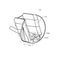
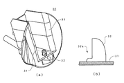
図1は、本発明にかかる給油ノズルの一実施の形態を示し、図1(a)は給油ノズル1の斜視図、図1(b)は、給油ノズル1のローラ7及びその近傍を下側から見た拡大図を示す。
FIG. 1 shows an embodiment of a fueling nozzle according to the present invention, FIG. 1 (a) is a perspective view of the
この給油ノズル1は、大別して、本体部2と、ノズル部3と、弁開レバー5を操作するための握り部4と、弁開レバー5を囲繞するレバーガード6とで構成される。
The
本体部2は、アルミニウム製で導電性を有し、その内部には主弁及び自動閉弁機構(不図示)が設けられる。本体部2の一端にはノズル部3が接続され、他端には、ガソリン等を給油ノズル1の本体部2に導入するためのホース(不図示)が接続される。
The
弁開レバー5は、握り部4から指で操作できるように本体部2から突設され、弁開レバー5を引くとガソリン等がノズル部3より吐出するように構成される。
The
握り部4及びレバーガード6は、ポリウレタン等の樹脂からなり、レバーガード6の下端部に、ノズル部3の延設方向に対して垂直な軸線回りに回転可能なローラ7が備えられ、このローラ7が後述する給油ノズル掛けの係止部に係止される。ローラ7は、給油ノズル1の側面(ノズル部3の延設方向、すなわち後述する給油ノズル1の収納方向に対して垂直な方向)から見たときに、レバーガード6の弁開レバー5とは反対側に突出するように備えられる。また、給油ノズル1の下側から見ると、図1(b)に示すように、ローラ7は、レバーガード6の間に配置される。
The grip portion 4 and the
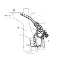
図2は、本発明にかかる給油ノズル掛けの一実施の形態を示し、上記給油ノズル1を載置する受け部及びその近傍のみを示す。この給油ノズル掛け10は、給油装置(不図示)の本体に装着され、給油ノズル1が載置される受け部11と、受け部11の入口近傍に突設された突出部(係止部)12と、給油ノズル1のレバーガード6を収納する収納箱13とで構成される。
FIG. 2 shows an embodiment of the oiling nozzle hook according to the present invention, and shows only the receiving portion on which the
受け部11上に位置する突出部12は、給油ノズル1の収納方向に対して垂直な方向から見て、頂部が鋭角の三角形状の突出部として形成され、奥側の面12aが手前側の面12bより緩勾配に形成される。
The
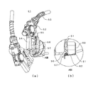
次に、上記構成を有する給油ノズル1を給油ノズル掛け10に収納する方法について、図3を参照しながら説明する。
Next, a method of housing the
給油ノズル1による給油が完了すると、人差し指を弁開レバー5から離し、給油ノズル1を把持した状態でノズル部3を給油ノズル掛け10に向けながら、レバーガード6を給油ノズル掛け10の収納箱13内に移動させ、レバーガード6を給油ノズル掛け10の受け部11に載置する。この際、レバーガード6のローラ7を給油ノズル掛け10の突出部12の奥側の面12aに載置する。すると、ローラ7は、回転しながら奥側の面12aを滑り落ちて停止し、最後に、給油ノズル1のノズル部3の先端が給油ノズル掛け10の収納空間14の天井面14aと当接し、給油ノズル1の給油ノズル掛け10への収納が終了する。
When the refueling by the refueling
以上のように、本実施の形態によれば、給油ノズル1においてレバーガード6から弁開レバー5の反対側に突出するローラ7を備えるとともに、突出部12を頂部が鋭角の三角形状に形成したため、ローラ7が給油ノズル掛け10の突出部12に不安定な状態で載置された状態となり難い上、顧客が給油ノズル1を給油ノズル掛け10に収納する際に、給油ノズル1のローラ7を給油ノズル掛け10の突出部12に接触させ易く、給油ノズル1の落下を効果的に防止することができる。
As described above, according to the present embodiment, the
また、給油ノズル掛け10の突出部12の奥側の面12aを緩勾配としているため、給油ノズル1のローラ7を奥側の面12aに載置し易くなり、給油ノズル1の落下を効果的に防止することができる。
Moreover, since the back surface 12a of the
さらに、給油ノズル1を給油ノズル掛け10に収納した後は、ローラ7が突出部12の頂部を乗り越えた位置にあるため、給油ノズル1が給油ノズル掛け10から外れて落下し難くなる。また、給油時に、給油ノズル掛け10に収納された給油ノズル1を引き出す際にも、ローラ7が回転することで給油ノズル1の引き出しを容易に行うこともできる。
Further, after the
尚、上記実施の形態においては、図1に示すように、レバーガード6の下端部に、ノズル部3の延設方向に対して垂直な軸線回りに回転可能なローラ7を設けたが、ローラ7に代えて、図4に示すように、レバーガード6に一体に固着され、給油ノズル1の収納方向に対して垂直な方向から見て円弧状に形成された突出部17とすることもできる。
In the above embodiment, as shown in FIG. 1, the
この突出部17は、ローラ7のように回転することはないが、レバーガード6から下方に突出しているため、突出部17が図2に示した給油ノズル掛け10の突出部12に不安定な状態で載置された状態となり難いとともに、顧客が給油ノズル1を給油ノズル掛け10に収納する際に、突出部17を給油ノズル掛け10の突出部12に接触させ易く、顧客が給油ノズル1を正規の位置に収納したことを容易に認識することができるため、給油ノズル1の落下を効果的に防止することができる。
Although this
次に、本発明にかかる給油ノズル掛けの他の実施の形態について、図面を参照しながら説明する。 Next, another embodiment of the oiling nozzle hook according to the present invention will be described with reference to the drawings.
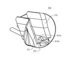
図5は、本発明にかかる給油ノズル掛けの第2の実施形態を示し、給油ノズルを載置する受け部及びその近傍のみを示す。この給油ノズル掛け20は、給油装置(不図示)の本体に装着され、例えば図1に示した給油ノズル1が載置される受け部21と、受け部21の入口近傍に突設された突出部(係止部)22と、給油ノズル1全体を収納する収納箱23とで構成される。
FIG. 5 shows a second embodiment of the fueling nozzle hook according to the present invention, and shows only the receiving portion on which the fueling nozzle is placed and the vicinity thereof. The oil
本実施の形態では、受け部21上に位置する突出部22は、給油ノズル1の収納方向に対して垂直な方向から見て、頂部が鋭角の三角形状の突出部として形成されているが、奥側の面22a及び手前側の面22bは略々同じ勾配を有する傾斜面となっている。このように突出部22を形成した場合でも、図2に示した給油ノズル掛け10のように突出部12の奥側の面12aを緩勾配とすることによる作用効果を奏することはないが、給油ノズル1のローラ7等が突出部22に不安定な状態で載置された状態となり難いなどの効果を奏し、給油ノズルの落下を効果的に防止することができる。
In the present embodiment, the protruding
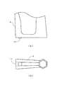
図5は、本発明にかかる給油ノズル掛けの第3の実施形態を示し、給油ノズルを載置する受け部及びその近傍のみを示す。この給油ノズル掛け30は、給油装置(不図示)の本体に装着され、例えば図1に示した給油ノズル1が載置される受け部31と、受け部31の入口近傍に突設された突出部(係止部)32と、給油ノズル1全体を収納する収納箱33とで構成される。
FIG. 5 shows a third embodiment of the fueling nozzle hook according to the present invention, and shows only the receiving portion on which the fueling nozzle is placed and the vicinity thereof. The oil
突出部32は、図6(b)に示すように、給油ノズル1の収納方向側に開口する切欠部32aを有するため、給油ノズル1のローラ7等が突出部32に不安定な状態で載置された状態となり難く、また、一旦ローラ7が切欠部32aに係止されると、突出部32の頂部を手前側に乗り越えることが困難であるため、給油ノズル1の落下を効果的に防止することができる。
As shown in FIG. 6 (b), the
尚、上記実施の形態においては、給油ノズル及び給油ノズル掛けの両方に本発明を適用した場合について説明したが、いずれか一方のみに本発明を適用し、他方は従来型を用いて給油装置を構成することもできる。例えば、図2、図5及び図6に示した給油ノズル掛けに図7に示したピン57を備えた給油ノズル51を用いても従来に比較して効果的に給油ノズル51の落下を防止することができる。
In the above embodiment, the case where the present invention is applied to both the oil supply nozzle and the oil supply nozzle hook has been described. However, the present invention is applied to only one of them, and the other is a conventional oil supply device. It can also be configured. For example, even if the
1 給油ノズル
2 本体部
3 ノズル部
4 握り部
5 弁開レバー
6 レバーガード
7 ローラ
10 給油ノズル掛け
11 受け部
12 係止部
12a 奥側の面
12b 手前側の面
13 収納箱
14 収納空間
14a 天井面
17 突出部
20 給油ノズル掛け
21 受け部
22 突出部
22a 奥側の面
22b 手前側の面
23 収納箱
30 給油ノズル掛け
31 受け部
32 係止部
32a 切欠部
33 収納箱
DESCRIPTION OF
Claims (8)
前記レバーガードに、前記弁開レバーの反対側に突出し、前記給油ノズル掛けに突設された係止部に係止される係止部を備えることを特徴とする給油ノズル。 A main body, a nozzle provided at one end of the main body, a grip opening provided at the other end of the main body for operating a valve opening lever protruding from the main body, and the valve opening lever. A refueling nozzle, which is provided with a surrounding lever guard and is housed in a refueling nozzle hook,
An oil supply nozzle, wherein the lever guard includes an engaging portion that protrudes to the opposite side of the valve opening lever and is engaged with an engaging portion that protrudes from the oil supply nozzle hook.
該係止部は、前記給油ノズルの収納方向に対して垂直な方向から見て、頂部が鋭角の三角形状に形成されることを特徴とする給油ノズル掛け。 A storage portion for storing the oil supply nozzle; and a receiving portion on which the oil supply nozzle is placed, and a locking portion projectingly engaged with the locking portion of the oil supply nozzle.
The locking portion is formed with a triangular shape with an apex as viewed from a direction perpendicular to the storage direction of the fuel nozzle.
該係止部は、前記給油ノズルの収納方向側に開口する切欠部を有することを特徴とする給油ノズル掛け。 A storage portion for storing the oil supply nozzle; and a receiving portion on which the oil supply nozzle is placed, and a locking portion projectingly engaged with the locking portion of the oil supply nozzle.
The locking portion has a notch that opens to the storage direction side of the fuel nozzle.
請求項5乃至7のいずれかに記載の給油ノズル掛けとを備えることを特徴とする給油装置。 Refueling nozzle according to any one of claims 1 to 4,
An oil supply apparatus comprising the oil supply nozzle hook according to any one of claims 5 to 7.
Priority Applications (1)
| Application Number | Priority Date | Filing Date | Title |
|---|---|---|---|
| JP2008319120A JP4858534B2 (en) | 2008-12-16 | 2008-12-16 | Lubrication nozzle |
Applications Claiming Priority (1)
| Application Number | Priority Date | Filing Date | Title |
|---|---|---|---|
| JP2008319120A JP4858534B2 (en) | 2008-12-16 | 2008-12-16 | Lubrication nozzle |
Publications (2)
| Publication Number | Publication Date |
|---|---|
| JP2010143584A true JP2010143584A (en) | 2010-07-01 |
| JP4858534B2 JP4858534B2 (en) | 2012-01-18 |
Family
ID=42564431
Family Applications (1)
| Application Number | Title | Priority Date | Filing Date |
|---|---|---|---|
| JP2008319120A Expired - Fee Related JP4858534B2 (en) | 2008-12-16 | 2008-12-16 | Lubrication nozzle |
Country Status (1)
| Country | Link |
|---|---|
| JP (1) | JP4858534B2 (en) |
Cited By (3)
| Publication number | Priority date | Publication date | Assignee | Title |
|---|---|---|---|---|
| JP2013230839A (en) * | 2012-04-27 | 2013-11-14 | Tominaga Oil Pump Mfg Co Ltd | Oil feeding nozzle and friction reduction cap |
| JP2022063460A (en) * | 2020-10-12 | 2022-04-22 | Eneos株式会社 | Oil supply device |
| CN116022718A (en) * | 2023-01-19 | 2023-04-28 | 易嘉油智能机器人有限责任公司 | An oil gun support structure |
Citations (2)
| Publication number | Priority date | Publication date | Assignee | Title |
|---|---|---|---|---|
| JPS53115920A (en) * | 1977-03-19 | 1978-10-09 | Tokico Ltd | Oil feed nozzle mount for oil feed device |
| JPS60158093A (en) * | 1984-01-27 | 1985-08-19 | 株式会社東京タツノ | Lubricating device |
-
2008
- 2008-12-16 JP JP2008319120A patent/JP4858534B2/en not_active Expired - Fee Related
Patent Citations (2)
| Publication number | Priority date | Publication date | Assignee | Title |
|---|---|---|---|---|
| JPS53115920A (en) * | 1977-03-19 | 1978-10-09 | Tokico Ltd | Oil feed nozzle mount for oil feed device |
| JPS60158093A (en) * | 1984-01-27 | 1985-08-19 | 株式会社東京タツノ | Lubricating device |
Cited By (4)
| Publication number | Priority date | Publication date | Assignee | Title |
|---|---|---|---|---|
| JP2013230839A (en) * | 2012-04-27 | 2013-11-14 | Tominaga Oil Pump Mfg Co Ltd | Oil feeding nozzle and friction reduction cap |
| JP2022063460A (en) * | 2020-10-12 | 2022-04-22 | Eneos株式会社 | Oil supply device |
| JP7248634B2 (en) | 2020-10-12 | 2023-03-29 | Eneos株式会社 | Lubricator |
| CN116022718A (en) * | 2023-01-19 | 2023-04-28 | 易嘉油智能机器人有限责任公司 | An oil gun support structure |
Also Published As
| Publication number | Publication date |
|---|---|
| JP4858534B2 (en) | 2012-01-18 |
Similar Documents
| Publication | Publication Date | Title |
|---|---|---|
| US8567458B2 (en) | Fuel filler apparatus of vehicle | |
| US20140306486A1 (en) | Door opening preventing apparatus for a vehicle | |
| US20160325621A1 (en) | System for filling at least one tank, motor vehicle comprising such a system and method for implementing such a system | |
| JP2011519774A (en) | Neck end for filler neck | |
| JP4892398B2 (en) | Filler pipe filler port structure | |
| JP4858534B2 (en) | Lubrication nozzle | |
| JP2007057997A (en) | Electrical equipment with a lid | |
| KR20090114949A (en) | Car fuel lubrication device | |
| JP5172397B2 (en) | accessory case | |
| JP5498254B2 (en) | Fuel supply device | |
| WO2018158872A1 (en) | Refueling nozzle | |
| JP7095755B2 (en) | vehicle | |
| JP6195738B2 (en) | Lever-operated injection device | |
| JP2006111073A (en) | Vehicle fuel lid structure | |
| JP4468916B2 (en) | Ball tray device for pachinko machines | |
| JP2008536758A (en) | Capless filler cover | |
| JP2010173662A (en) | Cold box | |
| JP3170714U (en) | Auto gas dispenser equipment | |
| JP2012180043A (en) | Structure of fuel filling part of fuel tank | |
| JP2011048429A (en) | Handle fixing structure | |
| JP2002309810A (en) | Flat handle device | |
| JP5081764B2 (en) | Refueling nozzle storage device and tank truck provided with the same | |
| JP5252632B2 (en) | Vehicle storage device | |
| JP2018016383A (en) | Oil feeding nozzle storage device and tank lorry therewith | |
| KR19990017594A (en) | Fuel cap retainer |
Legal Events
| Date | Code | Title | Description |
|---|---|---|---|
| A977 | Report on retrieval |
Free format text: JAPANESE INTERMEDIATE CODE: A971007 Effective date: 20110708 |
|
| A131 | Notification of reasons for refusal |
Free format text: JAPANESE INTERMEDIATE CODE: A131 Effective date: 20110712 |
|
| A521 | Request for written amendment filed |
Free format text: JAPANESE INTERMEDIATE CODE: A523 Effective date: 20110804 |
|
| A521 | Request for written amendment filed |
Free format text: JAPANESE INTERMEDIATE CODE: A523 Effective date: 20110808 |
|
| TRDD | Decision of grant or rejection written | ||
| A01 | Written decision to grant a patent or to grant a registration (utility model) |
Free format text: JAPANESE INTERMEDIATE CODE: A01 Effective date: 20111004 |
|
| A01 | Written decision to grant a patent or to grant a registration (utility model) |
Free format text: JAPANESE INTERMEDIATE CODE: A01 |
|
| A61 | First payment of annual fees (during grant procedure) |
Free format text: JAPANESE INTERMEDIATE CODE: A61 Effective date: 20111017 |
|
| R150 | Certificate of patent or registration of utility model |
Ref document number: 4858534 Country of ref document: JP Free format text: JAPANESE INTERMEDIATE CODE: R150 Free format text: JAPANESE INTERMEDIATE CODE: R150 |
|
| FPAY | Renewal fee payment (event date is renewal date of database) |
Free format text: PAYMENT UNTIL: 20141111 Year of fee payment: 3 |
|
| LAPS | Cancellation because of no payment of annual fees |