JP2010143569A - Switching system - Google Patents
Switching system Download PDFInfo
- Publication number
- JP2010143569A JP2010143569A JP2009284711A JP2009284711A JP2010143569A JP 2010143569 A JP2010143569 A JP 2010143569A JP 2009284711 A JP2009284711 A JP 2009284711A JP 2009284711 A JP2009284711 A JP 2009284711A JP 2010143569 A JP2010143569 A JP 2010143569A
- Authority
- JP
- Japan
- Prior art keywords
- switching
- position control
- control valve
- pressure medium
- piston
- Prior art date
- Legal status (The legal status is an assumption and is not a legal conclusion. Google has not performed a legal analysis and makes no representation as to the accuracy of the status listed.)
- Pending
Links
- 230000008878 coupling Effects 0.000 claims description 3
- 238000010168 coupling process Methods 0.000 claims description 3
- 238000005859 coupling reaction Methods 0.000 claims description 3
- 239000000470 constituent Substances 0.000 abstract 1
- 230000001360 synchronised effect Effects 0.000 description 2
- 230000000903 blocking effect Effects 0.000 description 1
- 238000004519 manufacturing process Methods 0.000 description 1
- KJFBVJALEQWJBS-XUXIUFHCSA-N maribavir Chemical compound CC(C)NC1=NC2=CC(Cl)=C(Cl)C=C2N1[C@H]1O[C@@H](CO)[C@H](O)[C@@H]1O KJFBVJALEQWJBS-XUXIUFHCSA-N 0.000 description 1
Images
Classifications
-
- F—MECHANICAL ENGINEERING; LIGHTING; HEATING; WEAPONS; BLASTING
- F16—ENGINEERING ELEMENTS AND UNITS; GENERAL MEASURES FOR PRODUCING AND MAINTAINING EFFECTIVE FUNCTIONING OF MACHINES OR INSTALLATIONS; THERMAL INSULATION IN GENERAL
- F16H—GEARING
- F16H61/00—Control functions within control units of change-speed- or reversing-gearings for conveying rotary motion ; Control of exclusively fluid gearing, friction gearing, gearings with endless flexible members or other particular types of gearing
- F16H61/26—Generation or transmission of movements for final actuating mechanisms
- F16H61/28—Generation or transmission of movements for final actuating mechanisms with at least one movement of the final actuating mechanism being caused by a non-mechanical force, e.g. power-assisted
- F16H61/30—Hydraulic or pneumatic motors or related fluid control means therefor
-
- B—PERFORMING OPERATIONS; TRANSPORTING
- B60—VEHICLES IN GENERAL
- B60K—ARRANGEMENT OR MOUNTING OF PROPULSION UNITS OR OF TRANSMISSIONS IN VEHICLES; ARRANGEMENT OR MOUNTING OF PLURAL DIVERSE PRIME-MOVERS IN VEHICLES; AUXILIARY DRIVES FOR VEHICLES; INSTRUMENTATION OR DASHBOARDS FOR VEHICLES; ARRANGEMENTS IN CONNECTION WITH COOLING, AIR INTAKE, GAS EXHAUST OR FUEL SUPPLY OF PROPULSION UNITS IN VEHICLES
- B60K17/00—Arrangement or mounting of transmissions in vehicles
- B60K17/34—Arrangement or mounting of transmissions in vehicles for driving both front and rear wheels, e.g. four wheel drive vehicles
- B60K17/344—Arrangement or mounting of transmissions in vehicles for driving both front and rear wheels, e.g. four wheel drive vehicles having a transfer gear
- B60K17/346—Arrangement or mounting of transmissions in vehicles for driving both front and rear wheels, e.g. four wheel drive vehicles having a transfer gear the transfer gear being a differential gear
- B60K17/3467—Arrangement or mounting of transmissions in vehicles for driving both front and rear wheels, e.g. four wheel drive vehicles having a transfer gear the transfer gear being a differential gear combined with a change speed gearing, e.g. range gear
-
- B—PERFORMING OPERATIONS; TRANSPORTING
- B60—VEHICLES IN GENERAL
- B60K—ARRANGEMENT OR MOUNTING OF PROPULSION UNITS OR OF TRANSMISSIONS IN VEHICLES; ARRANGEMENT OR MOUNTING OF PLURAL DIVERSE PRIME-MOVERS IN VEHICLES; AUXILIARY DRIVES FOR VEHICLES; INSTRUMENTATION OR DASHBOARDS FOR VEHICLES; ARRANGEMENTS IN CONNECTION WITH COOLING, AIR INTAKE, GAS EXHAUST OR FUEL SUPPLY OF PROPULSION UNITS IN VEHICLES
- B60K23/00—Arrangement or mounting of control devices for vehicle transmissions, or parts thereof, not otherwise provided for
- B60K23/08—Arrangement or mounting of control devices for vehicle transmissions, or parts thereof, not otherwise provided for for changing number of driven wheels, for switching from driving one axle to driving two or more axles
-
- F—MECHANICAL ENGINEERING; LIGHTING; HEATING; WEAPONS; BLASTING
- F16—ENGINEERING ELEMENTS AND UNITS; GENERAL MEASURES FOR PRODUCING AND MAINTAINING EFFECTIVE FUNCTIONING OF MACHINES OR INSTALLATIONS; THERMAL INSULATION IN GENERAL
- F16H—GEARING
- F16H61/00—Control functions within control units of change-speed- or reversing-gearings for conveying rotary motion ; Control of exclusively fluid gearing, friction gearing, gearings with endless flexible members or other particular types of gearing
- F16H61/26—Generation or transmission of movements for final actuating mechanisms
- F16H61/28—Generation or transmission of movements for final actuating mechanisms with at least one movement of the final actuating mechanism being caused by a non-mechanical force, e.g. power-assisted
- F16H2061/2869—Cam or crank gearing
-
- F—MECHANICAL ENGINEERING; LIGHTING; HEATING; WEAPONS; BLASTING
- F16—ENGINEERING ELEMENTS AND UNITS; GENERAL MEASURES FOR PRODUCING AND MAINTAINING EFFECTIVE FUNCTIONING OF MACHINES OR INSTALLATIONS; THERMAL INSULATION IN GENERAL
- F16H—GEARING
- F16H63/00—Control outputs from the control unit to change-speed- or reversing-gearings for conveying rotary motion or to other devices than the final output mechanism
- F16H63/02—Final output mechanisms therefor; Actuating means for the final output mechanisms
- F16H63/08—Multiple final output mechanisms being moved by a single common final actuating mechanism
- F16H63/16—Multiple final output mechanisms being moved by a single common final actuating mechanism the final output mechanisms being successively actuated by progressive movement of the final actuating mechanism
- F16H63/18—Multiple final output mechanisms being moved by a single common final actuating mechanism the final output mechanisms being successively actuated by progressive movement of the final actuating mechanism the final actuating mechanism comprising cams
-
- Y—GENERAL TAGGING OF NEW TECHNOLOGICAL DEVELOPMENTS; GENERAL TAGGING OF CROSS-SECTIONAL TECHNOLOGIES SPANNING OVER SEVERAL SECTIONS OF THE IPC; TECHNICAL SUBJECTS COVERED BY FORMER USPC CROSS-REFERENCE ART COLLECTIONS [XRACs] AND DIGESTS
- Y10—TECHNICAL SUBJECTS COVERED BY FORMER USPC
- Y10T—TECHNICAL SUBJECTS COVERED BY FORMER US CLASSIFICATION
- Y10T74/00—Machine element or mechanism
- Y10T74/20—Control lever and linkage systems
- Y10T74/20012—Multiple controlled elements
- Y10T74/20018—Transmission control
- Y10T74/20024—Fluid actuator
Landscapes
- Engineering & Computer Science (AREA)
- Mechanical Engineering (AREA)
- General Engineering & Computer Science (AREA)
- Chemical & Material Sciences (AREA)
- Combustion & Propulsion (AREA)
- Transportation (AREA)
- Arrangement And Mounting Of Devices That Control Transmission Of Motive Force (AREA)
- Arrangement And Driving Of Transmission Devices (AREA)
- Transmission Devices (AREA)
Abstract
Description
本発明は、特許請求の範囲の請求項1の上位概念部分に詳しく規定されたタイプに従う、全輪駆動車のためのメインギヤ内に設けられた分配ギヤを切り換えるための切換システムに関する。
The present invention relates to a switching system for switching a distribution gear provided in a main gear for an all-wheel drive vehicle, according to the type detailed in the superordinate conceptual part of
例えば、DE60204624T2から、自動車の分配ギヤのための切換制御システムが知られている。当該分配ギヤは、制御可能な2方向クラッチシステムを有している。前記切換システムは、様々な速度領域及び駆動モードを調整(投入)するべく、当該クラッチシステムを制御する。個々の駆動モード間での当該クラッチシステムの切換を制御するために、電気的に作動されるアクチュエータが、切換システムにおいて利用される。 For example, from DE 60204624T2, a switching control system for a distribution gear of a motor vehicle is known. The distribution gear has a controllable two-way clutch system. The switching system controls the clutch system to adjust (apply) various speed ranges and drive modes. In order to control the switching of the clutch system between the individual drive modes, an electrically actuated actuator is utilized in the switching system.
別の公知の切換システムにおいては、二輪駆動と四輪駆動との間での切換、並びに、様々なギヤ比間での切換が、電気モータを介して行われる。当該電気モータは、対応するように、切換装置を作動させる。電気モータを介しての作動は、しかしながら、以下のような欠点を有する。すなわち、必要な電力が一般には高コストであり、製造に関しても高コストで、故障も生じやすい。さらに、二輪駆動と四輪駆動との間での同期のために十分な切換力を提供するために、高いギヤ比が必要である。 In another known switching system, switching between two-wheel drive and four-wheel drive, as well as switching between various gear ratios, takes place via electric motors. The electric motor actuates the switching device in a corresponding manner. Operation via an electric motor, however, has the following drawbacks. That is, the required power is generally high-cost, manufacturing is also high-cost, and failure is likely to occur. Furthermore, a high gear ratio is required to provide sufficient switching force for synchronization between two-wheel drive and four-wheel drive.
本発明の課題は、当該明細書の導入部分で述べたような類の、全輪駆動車のためのメインギヤ内に設けられた分配ギヤを切り換えるための切換システムであって、切換装置の操作が簡単な態様で最小限の構造部品でコスト的にも有利に実現できる、という切換システムを提供することである。 An object of the present invention is a switching system for switching a distribution gear provided in a main gear for an all-wheel drive vehicle, as described in the introductory part of the specification, in which the operation of the switching device is performed. It is an object of the present invention to provide a switching system that can be realized in a simple manner with a minimum of structural components and also in terms of cost.
本発明の課題は、特許請求の範囲の請求項1に記載された特徴によって解決される。更なる有利な実施の形態が、下位請求項や図面から理解される。
The object of the invention is solved by the features described in
本発明によれば、全輪駆動車のためのメインギヤ内に設けられた分配ギヤを切り換えるための切換システムであって、少なくとも一つの操作可能な切換装置乃至その等価物を備えており、当該切換装置乃至その等価物は、異なる切換位置の投入のために、ハウジングまたはシリンダ内で移動可能な少なくとも一つのピストン乃至その等価物を介して、油圧式に作動可能であることを特徴とする切換システムが提供される。油圧を利用することによって、切換装置そして分配ギヤの制御のための高い切換力と特に短い切換時間とが、実現され得る。さらに、本発明の切換システムによれば、単一のピストンを利用することによって、頑丈かつ簡単に形成される構造(構造部品)が提供される。これにより、メンテナンスフリーで信頼性のある装置運転が実現できる。 According to the present invention, there is provided a switching system for switching a distribution gear provided in a main gear for an all-wheel drive vehicle, comprising at least one operable switching device or an equivalent thereof, Switching device characterized in that the device or its equivalent is hydraulically actuable via at least one piston or its equivalent movable in a housing or cylinder for the entry of different switching positions Is provided. By utilizing the hydraulic pressure, a high switching force and in particular a short switching time for the control of the switching device and the distribution gear can be realized. Furthermore, according to the switching system of the present invention, by using a single piston, a structure (structural component) is provided which is robust and easily formed. Thereby, a maintenance-free and reliable apparatus operation is realizable.
本発明の特に有利な実施の形態では、ピストンは、少なくとも2つの複数位置制御弁(Mehrwegeventile: multiway valve)乃至その等価物を介して、制御可能であり、当該少なくとも2つの複数位置制御弁は、前記メインギヤの圧力媒体供給部(5)を介して、供給可能である。この態様では、すでに存在するメインギヤの油圧システムを、全輪分配制御に利用することができる。当該制御の簡単な構成に基づいて、有利な態様では、ピストンの制御のために単一弁(Einfachventile)が利用され得る。 In a particularly advantageous embodiment of the invention, the piston is controllable via at least two multi-position control valves (Mehrwegeventile: multiway valve) or equivalent thereof, the at least two multi-position control valves being Supply is possible via the pressure medium supply section (5) of the main gear. In this aspect, the existing main gear hydraulic system can be used for all-wheel distribution control. Based on the simple configuration of the control, in an advantageous embodiment, a single valve (Einfachventile) can be used for the control of the piston.
本発明によって提供される一体型の全輪分配ギヤの油圧式の切換においては、例えば、前記ピストンは、ディスクカム乃至その等価物を介して、前記切換装置の切換フォークと作用結合可能であり、二輪駆動と四輪駆動との間の選択のための例えば同期クラッチを操作すべく、及び/または、所望のギヤ比投入のためのドグクラッチ乃至その等価物を操作すべく、前記切換フォークを制御するために、前記ピストンの平行移動が、結合ピンを介して、ディスクカムの開口内において、ディスクカムの回転運動に変換可能である。本発明による切換システムを介して制御可能な他の実施形態の切換装置もまた、可能である。 In the hydraulic switching of the integral all-wheel distribution gear provided by the present invention, for example, the piston can be operatively coupled to the switching fork of the switching device via a disc cam or equivalent thereof. The switching fork is controlled to operate, for example, a synchronous clutch for selection between two-wheel drive and four-wheel drive, and / or to operate a dog clutch or its equivalent for inputting a desired gear ratio. For this reason, the translation of the piston can be converted into the rotational motion of the disc cam in the opening of the disc cam via the coupling pin. Other embodiments of the switching device that are controllable via the switching system according to the invention are also possible.
本発明の最新の実施形態によれば、複数位置制御弁としては、例えば、少なくとも一つの第一の2位置制御弁と、少なくとも一つの第二の2位置制御弁と、が設けられ得る。切換装置を操作するための所望の切換位置を実現するために、別の弁態様も利用可能である。例えば、2つの単一弁(Einfachventile)を、高コストに形成される一つの弁で、置換することも可能である。 According to the latest embodiment of the present invention, as the multi-position control valve, for example, at least one first two-position control valve and at least one second two-position control valve can be provided. In order to realize the desired switching position for operating the switching device, other valve modes are also available. For example, it is possible to replace two single valves (Einfachventile) with one valve that is formed at a high cost.
好ましくは、第一切換位置は、前記双方の2位置制御弁の基本位置で実現され得る。第一切換位置の状態において、ピストンは、シリンダ室内の右側の端部位置にもたらされる。例えば、これは、圧力媒体が、メインギヤの圧力媒体供給部から前記双方の2位置制御弁の圧力媒体ポートを介して左側のシリンダ室内に導入可能であることによって、達成され得る。これによって、ピストンが、右側の端部位置にもたらされ、必要によっては当該位置に保持される。 Preferably, the first switching position can be realized at the basic position of both the two-position control valves. In the state of the first switching position, the piston is brought to the right end position in the cylinder chamber. For example, this can be achieved by allowing pressure medium to be introduced from the pressure medium supply of the main gear into the left cylinder chamber via the pressure medium ports of both two-position control valves. This brings the piston to the right end position and, if necessary, is held in that position.
第二切換位置では、ピストンは例えばシリンダ室内の中央位置にある。当該第二切換位置は、第一の2位置制御弁が第二の2位置制御弁に対して、圧力媒体ポートを介して圧力媒体が左側のシリンダ室内にも右側のシリンダ室内にも導入可能である、というように移動されることによって、達成され得る。これによって、ピストンが、中央位置にもたらされ、必要によっては当該位置に保持される。 In the second switching position, the piston is at a central position in the cylinder chamber, for example. In the second switching position, the first two-position control valve can introduce the pressure medium into the left cylinder chamber and the right cylinder chamber via the pressure medium port with respect to the second two-position control valve. It can be achieved by being moved. This brings the piston to a central position and if necessary holds it in that position.
次に、第三切換位置では、ピストンはシリンダ室内の左側の端部位置にある。当該第三切換位置は、第二の2位置制御弁をも、圧力媒体ポートを介して圧力媒体が右側のシリンダ室内に導入可能である、というように移動されることによって、達成され得る。これによって、ピストンが、左側の端部位置にもたらされ、必要によっては当該位置に保持される。 Next, in the third switching position, the piston is at the left end position in the cylinder chamber. The third switching position can be achieved by moving the second two-position control valve so that the pressure medium can be introduced into the right cylinder chamber via the pressure medium port. This brings the piston to the left end position and is held in that position if necessary.
ピストンを前述の各位置に保持するために、例えば、機械的なストッパ装置(Rastierung)乃至その等価物が、ディスクカム上に設けられ得る。これによれば、油圧式の制御は、圧力フリーに切り換えられ得る(遮断され得る)、という利点が生じる。有利な態様では、当該ストッパ装置は、切換装置の制御のための圧力媒体供給部の導通及び遮断のために、追加の複数位置制御弁と組み合わせられ得る。好ましくは、切換装置の切り換えが必要とされない時に、第一の2位置制御弁及び第二の2位置制御弁のための圧力媒体供給部を遮断するために、当該追加の複数位置制御弁は別の(前記の)複数位置制御弁に対して前置され得る。これにより、全体の油圧式の切換システムが、圧力フリーに切り換えられ得る。これによって、不必要な漏れや構造部材負荷が回避される。 In order to hold the piston in each of the aforementioned positions, for example, a mechanical stopper device (Rastierung) or its equivalent can be provided on the disc cam. This has the advantage that the hydraulic control can be switched to pressure-free (can be shut off). In an advantageous manner, the stopper device can be combined with an additional multi-position control valve for the conduction and shut-off of the pressure medium supply for the control of the switching device. Preferably, the additional multi-position control valve is separate to shut off the pressure medium supply for the first two-position control valve and the second two-position control valve when switching of the switching device is not required. Can be pre-positioned to the multi-position control valve (described above). Thereby, the entire hydraulic switching system can be switched pressure-free. This avoids unnecessary leakage and structural member loading.
各所定時において切換装置の位置を検知可能であるために、例えば、センサ装置乃至その等価物が、ディスクカムの回転角度を検出するために設けられ得る。 In order to be able to detect the position of the switching device at each predetermined time, for example, a sensor device or its equivalent may be provided to detect the rotation angle of the disc cam.
以下、本発明は、図面に基づいてより詳細に説明される。 Hereinafter, the present invention will be described in more detail based on the drawings.
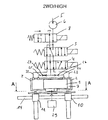
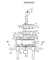
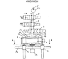
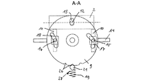
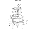
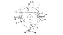
図1及び図1Aには、本発明による切換システムの2つの異なる実施の形態が、例示的に示されている。それらは、第一切換位置2WD/highの状態で示されている。図3乃至図6は、図1による切換システムの実施の形態において、更に可能性のある切換装置の切換位置4WD/highと4WD/lowとを示している。 1 and 1A exemplarily show two different embodiments of the switching system according to the invention. They are shown in the state of the first switching position 2WD / high. 3 to 6 show further possible switching positions 4WD / high and 4WD / low of the switching device in the embodiment of the switching system according to FIG.
それぞれの実施の形態に依存して、本発明による切換システムは、操作可能な切換装置を備えている。当該切換装置によって、全輪駆動車のためのメインギヤ内に設けられた分配ギヤが、切り換えられ得る。切換装置の操作のために、油圧式に作動可能なアクチュエータシステムが設けられている。当該アクチュエータシステムは、本質的に、ピストン1を有しており、当該ピストン1は、シリンダ2内において移動可能に配置されている。
Depending on the respective embodiment, the switching system according to the invention comprises an operable switching device. With this switching device, the distribution gear provided in the main gear for the all-wheel drive vehicle can be switched. A hydraulically actuable actuator system is provided for the operation of the switching device. The actuator system essentially has a
ピストン1の油圧式の制御のために、シリンダ2(ピストン1)は、第一の2位置制御弁3と、第二の2位置制御弁4と、を介して、図示されないメインギヤの圧力媒体供給部5と結合されている。圧力媒体供給部5は、特に、圧力媒体ポンプ6を有している。双方の2位置制御弁3、4を介して、シリンダ内部室7は、所望の切換位置にそれぞれ対応するような態様で圧力媒体で加圧される。シリンダ内部室7の中では、それに応じて、ピストン1が移動される。これにより、切換装置の3つの異なる切換位置2WD/high、4WD/high、4WD/lowを調整することが可能である。3つの異なる切換位置は、ここでは、ピストン1の両端位置と中央位置となっている。
For hydraulic control of the
図1Aに図示された実施の形態と異なり、図1に図示された実施の形態では、更なる2位置制御弁8が設けられている。これにより、切換装置の制御のための圧力媒体供給部5を導通及び遮断することが可能である。そのために、追加の2位置制御弁8は、双方の2位置制御弁3、4に対して前置される。この態様では、切換位置の変更が何ら所望されない時において、全体の切換システムが圧力フリーに切り換えられ得る。追加の2位置制御弁8は、また、図2乃至図6に図示された切換システムにおいても、設けられ得る。簡単のために、それらは図示されていない。あるいは、追加の2位置制御弁8を省略することもできる。簡単のために、それらは図示されていない。
Unlike the embodiment illustrated in FIG. 1A, in the embodiment illustrated in FIG. 1, a further two-
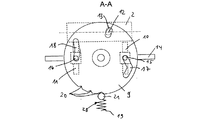
ピストン1は、ディスクカム9を介して、切換装置の第一切換フォーク10と第二切換フォーク11とに結合されている。ピストン1の平行移動が、結合ピン12を介して、ディスクカム9の開口13内において、ディスクカム9の回転運動に変換される。双方の切換フォーク10、11は、案内ロッド14上で、軸方向に移動可能に支持されている。この態様では、ディスクカム9は、それぞれの切換フォーク10、11を、その回転角度に依存して対応するように制御できる。これにより、クローラーギヤ比の無い二輪駆動(2WD/high)とクローラーギヤ比の無い四輪駆動(4WD/high)との間の選択のため、ないし、ギヤ比の追加的な選択のため、例えば、四輪駆動(4WD/low)のクローラーギヤ比への選択のために、分配ギヤが切り換えられ得る。二輪駆動(2WD/high)と四輪駆動(4WD/high)との間を切り換えるために、同期クラッチが、割り当てられた第一切換フォーク10を介して操作され得る。ギヤ比(4WD/low)の変更のためには、割り当てられた第二切換フォーク11を介して、ドグクラッチが操作され得る。ドグクラッチは、図には示されていない。以上のように提案される制御は、切換装置のそれぞれの実施の形態に依存する。
The
切換フォーク10、11は、ディスクカム9の割り当てられた案内溝17、18内で対応するピン15,16を介して案内される。これによって、切換フォーク10、11の対応する移動が、ディスクカム9の回転角度に依存して可能となる。このため、ディスクカム9の回転移動によって、案内ロッド14に沿った切換フォーク10、11の対応する軸方向移動が実現される。
The switching
ディスクカム9をそれぞれの切換位置に保持させるために、機械的なストッパ装置28が設けられている。このストッパ装置28は、圧力バネ19を介して対応する開口部20内に保持されるボール21を有している。複数の開口部20が、ピストン1の各切換位置に対応付けられている。従って、ディスクカム9の位置は、当該ストッパ装置28を介して、機械的に固定される。この状態で、圧力媒体供給部5は、追加の2位置制御弁8によって遮断され得る。これにより、切換システムは、圧力フリーになるが、ディスクカム9、従って、切換フォーク10、11は、ストッパ装置28によって、それらの所定位置に保持される。追加の2位置制御弁8は、例えば、電気的に制御され得る。これにより、圧力媒体供給部5の導通のための位置と遮断のための位置との間で、切り換えられ得る。所望の切換位置が達成された時、追加の2位置制御弁8は、図1、図3及び図5における矢印の方向に移動され得る。これにより、圧力媒体供給部5が遮断される。もっとも、他の制御態様も採用可能である。
In order to hold the disc cam 9 in each switching position, a
第一切換位置2WD/highは、図1に示されるように、追加の2位置制御弁8がまず圧力媒体供給部5を導通することによって、達成される。この状態では、第一の2位置制御弁3と第二の2位置制御弁4とが、それらの基本位置にある。この場合、双方の2位置制御弁3、4の圧力媒体ポートは、以下のように互いに対応付けられいる。すなわち、圧力媒体がメインギヤの圧力媒体供給部5から圧力媒体経路22を介して左側のシリンダ内部室7内に案内される、というように対応付けられている。これにより、ピストン1が、圧力媒体の加圧力によって、シリンダ内部室7の右側の端部位置に移動される。このような第一切換位置2WD/highは、図2に示されたディスクカム9及び切換フォーク10、11の位置に対応している。これにより、クローラーギヤ比の無い自動車についての二輪駆動を切り換えることができる。ここで、ディスクカム9と切換フォーク10、11とは、作用結合している。
The first switching position 2WD / high is achieved by the additional two-
図3には、第二切換位置4WD/highの切換装置が示されている。この場合、ピストン1は、シリンダ内部室7の中央位置にある。このような第二切換位置4WD/highを達成するために、圧力媒体は、メインギヤの圧力媒体供給部5から、導通された追加の2位置制御弁8を介して、双方の2位置制御弁3、4に案内される。このような第二切換位置4WD/highでは、第一の2位置制御弁3が以下のように移動されることが必要である。すなわち、双方の2位置制御弁3、4の圧力媒体ポートが、圧力媒体が圧力媒体経路22を介して左側のシリンダ内部室7内に案内されると共に別の圧力媒体経路23を介して右側のシリンダ内部室7内にも案内される、というように対応付けられる、ように移動される必要がある。この態様により、ピストン1がシリンダ内部室7の中央一にもたらされる。このような第二切換位置4WD/highは、図4に示されたディスクカム9及び切換フォーク10、11の位置に対応している。第二切換位置4WD/highでは、クローラーギヤ比の無い四輪駆動が、分配ギヤにおいて、ないし、自動車において、切り換えられる。
FIG. 3 shows a switching device at the second switching position 4WD / high. In this case, the
図5には、可能性ある第三切換位置4WD/lowの切換装置が示されている。このような第三切換位置4WD/lowを達成するために、第二の2位置制御弁4が以下のように移動される。すなわち、双方の2位置制御弁3、4の圧力媒体ポートが、メインギヤの圧力媒体供給部5からの圧力媒体が圧力媒体経路23を介して右側のシリンダ内部室7内に到達する、というように対応付けられるように移動される。圧力媒体の加圧力によって、ピストン1は、シリンダ内部室7の左側の端部位置にもたらされる。このような第三切換位置4WD/lowは、図6に示されたディスクカム9及び切換フォーク10、11の位置に対応している。第三切換位置4WD/lowでは、自動車の改善されたオフロード運転のための、クローラーギヤ比を有する四輪駆動が切り換えられる。
FIG. 5 shows a possible third switching position 4WD / low switching device. In order to achieve such a third switching position 4WD / low, the second two-
前述の各切換位置2WD/high、4WD/high、4WD/lowをシリンダ室内のピストン1によって調整可能とするべく、排気経路24、25が設けられている。それらには、好ましくは、それぞれ、スロットル(絞り)26、27が設けられる。
切換装置のそれぞれの実際の切換位置2WD/high、4WD/high、4WD/lowを検知するために、センサ装置29例えば回転角度センサないしその等価物が設けられることは、図1、図1A、図3及び図5から明らかである。
In order to detect each actual switching position 2WD / high, 4WD / high, 4WD / low of the switching device, a
1 ピストン
2 シリンダ
3 第一の2位置制御弁
4 第二の2位置制御弁
5 メインギヤの圧力媒体供給部
6 圧力媒体ポンプ
7 シリンダ内部室
8 追加の2位置制御弁
9 ディスクカム
10 第一切換フォーク
11 第二切換フォーク
13 開口
14 案内ロッド
15 ピン
16 ピン
17 案内溝
18 案内溝
19 圧力バネ
20 開口部
21 ボール
22 圧力媒体経路
23 圧力媒体経路
24 排気経路
25 排気経路
26 スロットル
27 スロットル
28 ストッパ装置
29 センサ装置
DESCRIPTION OF
Claims (11)
少なくとも一つの操作可能な切換装置を備えており、
当該切換装置は、異なる切換位置(2WD/high、4WD/high、4WD/low)の投入のために、シリンダ(2)内で移動可能な少なくとも一つのピストン(1)を介して、油圧式に作動可能である
ことを特徴とする切換システム。 A switching system for switching a distribution gear provided in a main gear for an all-wheel drive vehicle,
Comprising at least one operable switching device;
The switching device is hydraulically connected via at least one piston (1) movable in the cylinder (2) for the introduction of different switching positions (2WD / high, 4WD / high, 4WD / low). A switching system characterized by being operable.
前記少なくとも2つの複数位置制御弁は、前記メインギヤの圧力媒体供給部(5)を介して、供給可能である
ことを特徴とする請求項1に記載の切換システム。 The piston (1) is controllable via at least two multi-position control valves (Mehrwegeventile: multiway valve)
2. The switching system according to claim 1, wherein the at least two multi-position control valves can be supplied via a pressure medium supply section (5) of the main gear.
二輪駆動(2WD/high)と四輪駆動(4WD/high)との間の選択のためのクラッチを操作すべく、及び/または、所望のギヤ比投入のためのドグクラッチを操作すべく、前記切換フォーク(10、11)を制御するために、前記ピストン(1)の平行移動が、結合ピン(12)を介して、ディスクカム(9)の開口(13)内において、ディスクカム(9)の回転運動に変換可能である
ことを特徴とする請求項1または2に記載の切換システム。 The piston (1) is operatively coupled to the switching forks (10, 11) of the switching device via a disk cam (9),
Said switching to operate a clutch for selection between two-wheel drive (2WD / high) and four-wheel drive (4WD / high) and / or to operate a dog clutch for engaging a desired gear ratio In order to control the forks (10, 11), the translation of the piston (1) is effected via the coupling pin (12) in the opening (13) of the disc cam (9). The switching system according to claim 1, wherein the switching system can be converted into a rotational motion.
ことを特徴とする請求項2または3に記載の切換システム。 In order to adjust the piston (1) to a plurality of predetermined positions respectively corresponding to different switching positions (2WD / high, 4WD / high, 4WD / low) of the switching device, the multi-position control valve is at least one Switching system according to claim 2 or 3, characterized in that a first two-position control valve (3) and at least one second two-position control valve (4) are provided.
ことを特徴とする請求項4に記載の切換システム。 In order to input the first switching position (2WD / high) of the switching device, the two two-position control valves (3, 4) are arranged at their basic positions, and the pressure medium is supplied with the pressure medium. It can be introduced into the left cylinder chamber (7) from the part (5) via the pressure medium port of both the two-position control valves (3, 4), and the piston (1) is inserted into the cylinder chamber (7). 5. Switching system according to claim 4, characterized in that it is brought to the right end position.
ことを特徴とする請求項4または5に記載の切換システム。 In order to input the second switching position (4WD / high) of the switching device, the first two-position control valve (3) is connected to the second two-position control valve (4) via the pressure medium port. The pressure medium can be introduced into the left cylinder chamber (7) and the right cylinder chamber (7) so that the piston (1) is moved to the center position in the cylinder chamber (7). The switching system according to claim 4 or 5, characterized in that the switching system is provided.
ことを特徴とする請求項4乃至6のいずれかに記載の切換システム。 In order to turn on the third switching position (4WD / low) of the switching device, the second two-position control valve (4) is also inserted into the right cylinder chamber (7) via the pressure medium port. 7. The device as claimed in claim 4, wherein the piston (1) is moved to the left end position in the cylinder chamber (7). Switching system according to.
ことを特徴とする請求項1乃至7のいずれかに記載の切換システム。 8. Switching system according to any one of the preceding claims, characterized in that a mechanical stopper device (28) is provided for detecting the rotational angle of the disc cam (9).
ことを特徴とする請求項1乃至8のいずれかに記載の切換システム。 9. Switching system according to claim 1, wherein the sensor device (29) is provided for detecting the rotational angle of the disc cam (9).
ことを特徴とする請求項1乃至9のいずれかに記載の切換システム。 Switching according to any one of the preceding claims, characterized in that an additional multi-position control valve is provided for the conduction and shut-off of the pressure medium supply (5) for the control of the switching device. system.
当該追加の2位置制御弁(8)は、第一の2位置制御弁(3)及び第二の2位置制御弁(4)に対して前置されている
ことを特徴とする請求項10に記載の切換システム。 The additional multi-position control valve is configured as a two-position control valve (8),
11. The additional two-position control valve (8) is placed in front of the first two-position control valve (3) and the second two-position control valve (4). The switching system described.
Applications Claiming Priority (1)
| Application Number | Priority Date | Filing Date | Title |
|---|---|---|---|
| DE102008054977.0A DE102008054977B4 (en) | 2008-12-19 | 2008-12-19 | switching arrangement |
Publications (1)
| Publication Number | Publication Date |
|---|---|
| JP2010143569A true JP2010143569A (en) | 2010-07-01 |
Family
ID=42243411
Family Applications (1)
| Application Number | Title | Priority Date | Filing Date |
|---|---|---|---|
| JP2009284711A Pending JP2010143569A (en) | 2008-12-19 | 2009-12-16 | Switching system |
Country Status (3)
| Country | Link |
|---|---|
| US (1) | US20100154576A1 (en) |
| JP (1) | JP2010143569A (en) |
| DE (1) | DE102008054977B4 (en) |
Cited By (1)
| Publication number | Priority date | Publication date | Assignee | Title |
|---|---|---|---|---|
| RU188504U1 (en) * | 2018-12-28 | 2019-04-16 | федеральное государственное бюджетное образовательное учреждение высшего образования "Московский государственный технический университет имени Н.Э. Баумана (национальный исследовательский университет)" (МГТУ им. Н.Э. Баумана) | Drive control of the camshaft transfer case for camshaft with double screw mechanism |
Families Citing this family (4)
| Publication number | Priority date | Publication date | Assignee | Title |
|---|---|---|---|---|
| DE102014206382A1 (en) * | 2014-04-03 | 2015-10-08 | Zf Friedrichshafen Ag | Switchable gearbox for an agricultural vehicle |
| US10343519B2 (en) * | 2016-06-23 | 2019-07-09 | Dana Heavy Vehicle Systems Group, Llc | Mechanical shift assembly for a shiftable tandem drive axle |
| CN106274746B (en) * | 2016-08-31 | 2018-12-25 | 北汽福田汽车股份有限公司 | The control system and 4 wheel driven truck of 4 wheel driven truck |
| US12024020B2 (en) * | 2019-08-28 | 2024-07-02 | Nissan Motor Co., Ltd. | Power transmission device |
Citations (9)
| Publication number | Priority date | Publication date | Assignee | Title |
|---|---|---|---|---|
| JPS61175349A (en) * | 1985-01-30 | 1986-08-07 | Iseki & Co Ltd | Speed change operating device |
| JPS6225223U (en) * | 1985-07-30 | 1987-02-16 | ||
| JPS6227734Y2 (en) * | 1979-07-19 | 1987-07-16 | ||
| JPS6313545Y2 (en) * | 1982-02-23 | 1988-04-18 | ||
| JPH032689B2 (en) * | 1985-12-23 | 1991-01-16 | Daihatsu Motor Co Ltd | |
| JPH0318773Y2 (en) * | 1985-06-05 | 1991-04-19 | ||
| JPH0460844B2 (en) * | 1986-04-17 | 1992-09-29 | Toyota Motor Co Ltd | |
| JPH0660697B2 (en) * | 1985-12-30 | 1994-08-10 | ヘルビガー・ヴェンティールヴェルケ・アクチェンゲゼルシャフト | 5-port 3-position directional control valve unit |
| JPH1016590A (en) * | 1996-07-05 | 1998-01-20 | Mitsubishi Motors Corp | Control device and switching device of power transmission device for vehicle |
Family Cites Families (9)
| Publication number | Priority date | Publication date | Assignee | Title |
|---|---|---|---|---|
| US3688596A (en) * | 1969-06-17 | 1972-09-05 | Imre Szodfridt | Shifting mechanism for multi-speed transmission |
| AU3380478A (en) * | 1977-03-06 | 1979-09-06 | Rosenberg P | Steppable mechanism and valves including same |
| US4475695A (en) * | 1982-12-13 | 1984-10-09 | Burr Oak Tool & Gauge Company | Power assist uncoiler |
| US5443429A (en) * | 1993-11-30 | 1995-08-22 | Dana Corporation | Automatic powershifting transfer case for a vehicle |
| US6079535A (en) * | 1999-04-01 | 2000-06-27 | New Venture Gear, Inc. | Transfer case with disconnectable transfer clutch |
| EP1132661B1 (en) * | 2000-03-10 | 2004-03-17 | Honda Giken Kogyo Kabushiki Kaisha | Method and apparatus for controlling gear-shift of motor-driven gear shifter |
| US6629474B2 (en) * | 2001-04-27 | 2003-10-07 | New Venture Gear, Inc. | On-demand transfer case with controllable bi-directional overrunning clutch assembly |
| US7601095B2 (en) * | 2005-07-20 | 2009-10-13 | Kanzaki Kokyukoki Mfg. Co., Ltd. | Vehicle |
| US8647225B2 (en) * | 2007-11-29 | 2014-02-11 | Ford Global Technologies, Llc | Transfer case for a motor vehicle powertrain |
-
2008
- 2008-12-19 DE DE102008054977.0A patent/DE102008054977B4/en not_active Expired - Fee Related
-
2009
- 2009-11-06 US US12/613,573 patent/US20100154576A1/en not_active Abandoned
- 2009-12-16 JP JP2009284711A patent/JP2010143569A/en active Pending
Patent Citations (9)
| Publication number | Priority date | Publication date | Assignee | Title |
|---|---|---|---|---|
| JPS6227734Y2 (en) * | 1979-07-19 | 1987-07-16 | ||
| JPS6313545Y2 (en) * | 1982-02-23 | 1988-04-18 | ||
| JPS61175349A (en) * | 1985-01-30 | 1986-08-07 | Iseki & Co Ltd | Speed change operating device |
| JPH0318773Y2 (en) * | 1985-06-05 | 1991-04-19 | ||
| JPS6225223U (en) * | 1985-07-30 | 1987-02-16 | ||
| JPH032689B2 (en) * | 1985-12-23 | 1991-01-16 | Daihatsu Motor Co Ltd | |
| JPH0660697B2 (en) * | 1985-12-30 | 1994-08-10 | ヘルビガー・ヴェンティールヴェルケ・アクチェンゲゼルシャフト | 5-port 3-position directional control valve unit |
| JPH0460844B2 (en) * | 1986-04-17 | 1992-09-29 | Toyota Motor Co Ltd | |
| JPH1016590A (en) * | 1996-07-05 | 1998-01-20 | Mitsubishi Motors Corp | Control device and switching device of power transmission device for vehicle |
Cited By (1)
| Publication number | Priority date | Publication date | Assignee | Title |
|---|---|---|---|---|
| RU188504U1 (en) * | 2018-12-28 | 2019-04-16 | федеральное государственное бюджетное образовательное учреждение высшего образования "Московский государственный технический университет имени Н.Э. Баумана (национальный исследовательский университет)" (МГТУ им. Н.Э. Баумана) | Drive control of the camshaft transfer case for camshaft with double screw mechanism |
Also Published As
| Publication number | Publication date |
|---|---|
| DE102008054977A1 (en) | 2010-07-15 |
| US20100154576A1 (en) | 2010-06-24 |
| DE102008054977B4 (en) | 2014-01-23 |
Similar Documents
| Publication | Publication Date | Title |
|---|---|---|
| US9435384B2 (en) | Actuator arrangement for a motor vehicle train | |
| US9309968B2 (en) | Shift arrangement for a motor vehicle gearbox | |
| JP2010143569A (en) | Switching system | |
| US10408284B2 (en) | Hydraulic system for a vehicle | |
| CN105179672A (en) | Variator lockout valve system | |
| KR20070103440A (en) | Shifting device for a transmission | |
| US20020148310A1 (en) | Hydraulic control system of automated manual transmission | |
| CN106170647B (en) | hydraulic transmission actuator | |
| JPH06174085A (en) | Hydraulic parking device for automatic transmission | |
| CN105121915A (en) | Functional unit for shifting and controlling a gearbox | |
| EP2773889A1 (en) | A transmission protection system | |
| JP2019056408A (en) | Shift control device | |
| EP1222415B1 (en) | Gear box mechanism | |
| CN202326487U (en) | Reversing valve and multichannel reversing valve | |
| JPH08109905A (en) | Multiple stage stroke cylinder control device and hydraulic control device for automatic transmission using it | |
| JPH0868463A (en) | Multistage stroke cylinder device and automatic transmission hydraulic control device using multistage stroke cylinder device | |
| JP6594386B2 (en) | Shift control device | |
| JP6817866B2 (en) | Shift control device | |
| JPH084897A (en) | Gear shifting device for pneumatic type transmission | |
| JP2004316862A (en) | Range switching device for vehicle | |
| CN101258344A (en) | Cable valve | |
| JP2019070434A (en) | Shift-by-wire device | |
| JP6767911B2 (en) | Shift control device | |
| JP2014119068A (en) | Dual clutch type transmission | |
| KR101976617B1 (en) | Oil pressure control system for controlling auto transmission |
Legal Events
| Date | Code | Title | Description |
|---|---|---|---|
| RD03 | Notification of appointment of power of attorney |
Free format text: JAPANESE INTERMEDIATE CODE: A7423 Effective date: 20111111 |
|
| RD04 | Notification of resignation of power of attorney |
Free format text: JAPANESE INTERMEDIATE CODE: A7424 Effective date: 20120412 |
|
| A621 | Written request for application examination |
Free format text: JAPANESE INTERMEDIATE CODE: A621 Effective date: 20121206 |
|
| A131 | Notification of reasons for refusal |
Free format text: JAPANESE INTERMEDIATE CODE: A131 Effective date: 20140121 |
|
| A02 | Decision of refusal |
Free format text: JAPANESE INTERMEDIATE CODE: A02 Effective date: 20140902 |