JP2010143567A - Method and device for outputting travel information - Google Patents
Method and device for outputting travel information Download PDFInfo
- Publication number
- JP2010143567A JP2010143567A JP2009282377A JP2009282377A JP2010143567A JP 2010143567 A JP2010143567 A JP 2010143567A JP 2009282377 A JP2009282377 A JP 2009282377A JP 2009282377 A JP2009282377 A JP 2009282377A JP 2010143567 A JP2010143567 A JP 2010143567A
- Authority
- JP
- Japan
- Prior art keywords
- vehicle
- acceleration
- travel information
- inf
- actual
- Prior art date
- Legal status (The legal status is an assumption and is not a legal conclusion. Google has not performed a legal analysis and makes no representation as to the accuracy of the status listed.)
- Pending
Links
Images
Classifications
-
- B—PERFORMING OPERATIONS; TRANSPORTING
- B60—VEHICLES IN GENERAL
- B60W—CONJOINT CONTROL OF VEHICLE SUB-UNITS OF DIFFERENT TYPE OR DIFFERENT FUNCTION; CONTROL SYSTEMS SPECIALLY ADAPTED FOR HYBRID VEHICLES; ROAD VEHICLE DRIVE CONTROL SYSTEMS FOR PURPOSES NOT RELATED TO THE CONTROL OF A PARTICULAR SUB-UNIT
- B60W50/00—Details of control systems for road vehicle drive control not related to the control of a particular sub-unit, e.g. process diagnostic or vehicle driver interfaces
- B60W50/08—Interaction between the driver and the control system
- B60W50/14—Means for informing the driver, warning the driver or prompting a driver intervention
-
- Y—GENERAL TAGGING OF NEW TECHNOLOGICAL DEVELOPMENTS; GENERAL TAGGING OF CROSS-SECTIONAL TECHNOLOGIES SPANNING OVER SEVERAL SECTIONS OF THE IPC; TECHNICAL SUBJECTS COVERED BY FORMER USPC CROSS-REFERENCE ART COLLECTIONS [XRACs] AND DIGESTS
- Y02—TECHNOLOGIES OR APPLICATIONS FOR MITIGATION OR ADAPTATION AGAINST CLIMATE CHANGE
- Y02T—CLIMATE CHANGE MITIGATION TECHNOLOGIES RELATED TO TRANSPORTATION
- Y02T10/00—Road transport of goods or passengers
- Y02T10/80—Technologies aiming to reduce greenhouse gasses emissions common to all road transportation technologies
- Y02T10/84—Data processing systems or methods, management, administration
Landscapes
- Engineering & Computer Science (AREA)
- Automation & Control Theory (AREA)
- Human Computer Interaction (AREA)
- Transportation (AREA)
- Mechanical Engineering (AREA)
- Control Of Vehicle Engines Or Engines For Specific Uses (AREA)
- Instrument Panels (AREA)
- Control Of Driving Devices And Active Controlling Of Vehicle (AREA)
Abstract
【課題】利用者に対して車両の燃料消費を削減することを容易にする方法及び装置を提供する。
【解決手段】車両(20)のドライバーにエネルギー消費的に最適な走行状態を指示する、走行情報(INF)を出力する方法は、車両の実際の運転状態パラメータの内の少なくとも一つ(P1)並びに走行抵抗パラメータの内の少なくとも一つ(P2)に応じて燃費的に最適な車両目標加速度(B1)を測定し、車両実加速度(B2)を測定し、測定された車両目標加速度(B1)と車両実加速度(B2)とに応じて走行情報INFを生成し、走行情報(INF)を出力する。
【選択図】図1A method and apparatus that facilitates reducing fuel consumption of a vehicle for a user.
A method of outputting travel information (INF) for instructing a driver of a vehicle (20) an optimal travel state in terms of energy consumption is at least one of the actual drive state parameters of the vehicle (P1). In addition, the vehicle target acceleration (B1) that is optimal in terms of fuel efficiency is measured according to at least one of the running resistance parameters (P2), the vehicle actual acceleration (B2) is measured, and the measured vehicle target acceleration (B1) is measured. Travel information INF is generated according to the vehicle actual acceleration (B2) and the travel information (INF) is output.
[Selection] Figure 1
Description
本発明は、車両のドライバーに対して、ドライバーが車両のエネルギー消費的に最適な走行状態について知らされるように、走行情報を出力するための方法及び装置に関する。 The present invention relates to a method and apparatus for outputting driving information so that a driver of a vehicle is informed about a driving state that is optimal in terms of energy consumption of the vehicle.
CO2論議によって又上昇しつつあるエネルギーコストに刺激されて、このところ燃料消費量の削減及びそれに伴う有害物質排出の削減に対して、ますます価値が置かれるようになって来ている。エンジンと車両の駆動装置を効率的に仕立て上げるために、大きな技術的努力が行われている(可変バルブストローク、シリンダカットオフ、ハイブリッド駆動装置等)。効率を高めるこれ等のシステムを用いて、実際の運転状態(基本的にエンジン回転数、シフトされているギヤ、車速、及び加速によって決定することができる)の下で燃費を低減させることができる。 Stimulated by the rising energy costs due to the CO 2 debate, more and more value is being placed on the recent reduction in fuel consumption and associated emission of harmful substances. Great technical efforts have been made to efficiently tailor engine and vehicle drives (variable valve stroke, cylinder cut-off, hybrid drive, etc.). These systems that increase efficiency can reduce fuel consumption under actual driving conditions (which can basically be determined by engine speed, gears being shifted, vehicle speed, and acceleration) .
しかしながら、実際の運転状態を選択するのはドライバーである。ドライバーに対して燃料消費的に最適な運転状態を示すために車両のメーターパネルの中の幾つかの表示が用いられる。その際、一般に燃料消費量の表示やいわゆる“シフトアップインジケータ”或いは“レンジインジケータ”が用いられている。後者はドライバーに対して省エネ走行運転を可能にするギヤシフトの仕方を指示することを目的としている。 However, it is the driver who selects the actual driving state. Several indications in the vehicle's meter panel are used to indicate to the driver the optimal fuel consumption driving conditions. At that time, a display of fuel consumption or a so-called “shift-up indicator” or “range indicator” is generally used. The latter is intended to instruct the driver how to shift gears to enable energy-saving driving.
従来技術として知られている燃料消費表示の欠点は、その時の走行状況の下でエネルギー消費的に或いは燃料消費的に、より有利な運転状態がどの程度可能であるか、ドライバーに対してその燃費表示によっては示されないという点にある。表示される数値は絶対値であり、燃費の削減という意味から先ずドライバーによって解釈されなければならないので、この表示は、ドライバーにとって直ちに自分の走り方を最適化するためには役立たない。実際の走行状況においてどこに燃費的により有利な運転状態があるかという指示は、この消費表示からは得られない。 The drawback of the fuel consumption display known as the prior art is that it is possible for the driver to determine the more advantageous driving state in terms of energy consumption or fuel consumption under the driving conditions at that time, and the fuel consumption to the driver. It is in that it is not shown depending on the display. Since the displayed value is an absolute value and must first be interpreted by the driver in the sense of reducing fuel consumption, this display is not useful for the driver to immediately optimize his driving style. An indication of where the driving state is more advantageous in terms of fuel consumption in the actual driving situation cannot be obtained from this consumption display.
従来技術における“シフトアップインジケータ”或いは“レンジインジケータ”は、“適正な”ギヤで走るためには良い補助手段である。しかしながら、定速走行の際に或いは二つのシフトポイントの間で、即ち一つのギヤチェンジから次のギヤチェンジまでの間で、消費量を減らそうとすると、たちまち欠点が現れて来る。 The “shift-up indicator” or “range indicator” in the prior art is a good auxiliary means to run with the “right” gear. However, when trying to reduce consumption during constant speed travel or between two shift points, that is, from one gear change to the next, a shortcoming appears.
ほぼ同じままの速度を特徴とする定速走行の場合に、ドライバーがアクセルペダルの操作によって駆動トルクを定速運転のために必要である以上に高めても、車は気付かれぬ程しか加速しない、ということが明らかとなる。しかしながら、そのような僅かな加速は、車の場合ドライバーによって正しく認知され、又識別されることができない。このことは、ドライバーが特別な影響によってハンドル操作したり或いは集中力を欠いている場合には、ますますそうなる。場合によっては、ドライバーは数キロメートルを走った後に初めて速度が上がっていることに気が付き、あらためて速度を再び僅かに落とすために、アクセルペダルを戻すことによって駆動トルクを落とすかも知れない。その際、ドライバーが上り坂で無意識にわずかに加速するような時には不都合となる。何故なら、不必要な加速は不釣り合いな程余分なエネルギー或いは燃料を要するからである。この場合には“シフトアップインジケータ”は役に立たない。何故なら、このインジケータは僅かな変化については何らの有効な操作指示も与えてはくれないからである。 When driving at a constant speed, which is characterized by almost the same speed, even if the driver increases the driving torque beyond what is necessary for constant speed driving by operating the accelerator pedal, the car will only accelerate to an unnoticeable degree. It becomes clear that. However, such slight acceleration cannot be correctly recognized and identified by the driver in the case of a car. This is even more so if the driver is handling the steering wheel due to special effects or lacks concentration. In some cases, the driver may notice that the speed is increasing only after driving a few kilometers and may reduce the driving torque by returning the accelerator pedal to reduce the speed slightly again. This is inconvenient when the driver unconsciously slightly accelerates uphill. This is because unnecessary acceleration requires disproportionately extra energy or fuel. In this case, the “shift-up indicator” is useless. This is because this indicator does not give any effective operating instructions for slight changes.
従って、本発明の課題は、利用者に対して車両の燃料消費を削減することを容易にする方法及び装置を提供することである。 Accordingly, it is an object of the present invention to provide a method and apparatus that facilitates reducing fuel consumption of a vehicle for a user.
この課題は、請求項に記載の方法および装置によって解決される。 This problem is solved by the methods and devices described in the claims.
第一の実施態様によれば、以下の諸ステップを用いて車両のドライバーにエネルギー消費的に最適な走行状態を示す走行情報を出力するための方法は、
車両の実際の運転状態パラメータの内の少なくとも一つ並びに走行抵抗パラメータの内の少なくとも一つに応じた、燃費的に最適な車両目標加速を測定するステップと、
車両実加速度を測定するステップと、
測定された車両目標加速度と車両実加速度とに応じた走行情報を生成するステップと、
走行情報を出力するステップと、
を含む。
According to the first embodiment, a method for outputting travel information indicating an optimal travel state in terms of energy consumption to a vehicle driver using the following steps:
Measuring a fuel target optimum acceleration according to at least one of the actual driving state parameters of the vehicle and at least one of the driving resistance parameters;
Measuring the actual vehicle acceleration;
Generating travel information according to the measured vehicle target acceleration and the actual vehicle acceleration;
Outputting driving information;
including.
更に有利な一実施態様では、運転状態パラメータの内の少なくとも一つが車速及び/又はエンジン回転数を含むことができる。 In a further advantageous embodiment, at least one of the operating state parameters may include vehicle speed and / or engine speed.
別の実施態様によれば、目標加速度の測定のために援用される実際の運転状態パラメータの内の少なくとも一つは車両実加速度、走行レンジ情報、車重に関するデータ、並びに車両がトレーラー(被牽引車)付きで運転されているか否かというデータの内の少なくとも一つのパラメータを含むことができる。 According to another embodiment, at least one of the actual driving condition parameters used for measuring the target acceleration is vehicle actual acceleration, travel range information, vehicle weight data, and the vehicle is trailer (towed). It may include at least one parameter of data on whether or not the vehicle is being driven.
更に、走行情報は、ドライバーが、車両実加速度が燃費的に最適な走行状態の車両目標加速度よりも小さいか或いは大きいかということを認知するように出されることができる。 Furthermore, the driving information can be issued so that the driver recognizes whether the vehicle actual acceleration is smaller or larger than the vehicle target acceleration in the driving state that is optimal in terms of fuel consumption.
別の実施態様では、走行情報が、とりわけ走行レンジに応じて異なる重み付け係数を用いて重み付けされ或いは評価されることができる。かくして、ケース毎に、例えばその時々の走行レンジに応じて、異なる重み付け係数が可能となる。 In another embodiment, the travel information can be weighted or evaluated using different weighting factors depending on, among other things, the travel range. Thus, different weighting factors are possible for each case, for example, depending on the running range at that time.
一実施態様によれば、走行情報は車両の中で視覚的及び/又は触覚的及び/又は音響的出力によって与えることができる。 According to one embodiment, the driving information can be provided in the vehicle by visual and / or tactile and / or acoustic output.
更に、この方法は、別の実施態様では、定速走行運転中に及び/又は二つのシフトポイント、即ち第一のシフトポイントは一つのギヤが入れられるクラッチ接続の時点を意味しており又第二のシフトポイントは別のギヤに入れられるクラッチ遮断の時点を意味している、の間の加速過程で利用されることができる。 Furthermore, the method may, in another embodiment, refer to the point of clutch engagement during constant speed operation and / or two shift points, i.e. the first shift point is one gear is engaged. The second shift point can be used in the acceleration process during, which means the point of clutch disengagement that is put into another gear.
別の実施態様によれば、車のドライバーにエネルギー消費的に最適な走行状態を指示する走行情報を出力するための装置は、
車の実際の運転状態パラメータの内の少なくとも一つ並びに走行抵抗パラメータの内の少なくとも一つに応じて、燃費的に最適な車両目標加速度を測定するための測定装置と、
車両実加速度の測定のためのセンサ装置と、
測定された車両目標加速度及び車両実加速度に応じて、走行情報を生成するための装置と、
走行情報を出力するための出力装置と
を備えている。
According to another embodiment, an apparatus for outputting driving information that instructs a driving state optimal for energy consumption to a driver of a car includes:
A measuring device for measuring the optimum vehicle target acceleration in terms of fuel consumption according to at least one of the actual driving state parameters of the vehicle and at least one of the driving resistance parameters;
A sensor device for measuring the actual acceleration of the vehicle;
An apparatus for generating travel information according to the measured vehicle target acceleration and the actual vehicle acceleration;
And an output device for outputting travel information.
別の実施態様によれば、上述の走行情報を出力するための装置を備えた車両が提案される。 According to another embodiment, a vehicle equipped with a device for outputting the above-mentioned travel information is proposed.
別の実施態様によれば、データ処理ユニットで実行されると上記の走行を実施するコンピュータプログラムが提案される。 According to another embodiment, a computer program is proposed which, when executed on a data processing unit, implements the above running.
本発明の好ましい実施態様が以下に付属の図面に基づいて詳しく説明される。 Preferred embodiments of the present invention will be described in detail below with reference to the accompanying drawings.
以下の説明と図面の中で同じ参照記号は、同じ又は類似の機能の要素或いは同じ又は類似の方法におけるステップに対応している。 In the following description and drawings, the same reference symbols correspond to elements of the same or similar function or steps in the same or similar method.
加速度という概念は、ここでは正の加速度だけではなく負の加速度(減速度)をも含んでいる。更に、加速度という用語は、ここでは常に車の長手方向の加速度或いは駆動方向の車両加速度を意味している。路面勾配という概念は、水平面に対する路面の登り又は下りを意味しており、従って、登りや下りという意味での路面勾配は、ある場合には路面と水平面との間のゼロではない角度を意味している。エンジンに依存してない、車の長手方向の力が働いている時には路面勾配がある。 Here, the concept of acceleration includes not only positive acceleration but also negative acceleration (deceleration). Furthermore, the term acceleration here always means acceleration in the longitudinal direction of the vehicle or vehicle acceleration in the driving direction. The concept of road slope refers to ascending or descending of the road surface relative to the horizontal plane, and therefore road slope in the sense of climbing or descending means in some cases a non-zero angle between the road surface and the horizontal plane. ing. There is a road gradient when the longitudinal force of the car is working, not depending on the engine.
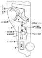
図1には例示として、本発明に基づく方法を実施するための装置10が車両20と関連付けて示されている。装置10は、好ましくは車両20、例えば乗用車或いは貨物車両、さもなければ、例えば二輪車の中に装着されている。
FIG. 1 shows, by way of example, an apparatus 10 for carrying out the method according to the invention in association with a
装置10は、燃費的に最適な車両目標加速度の測定のための測定装置B1の測定のための測定装置30を含んでいる。その際、この測定装置30は、車両20の制御装置40、例えば駆動エンジン50の制御に用いられるエンジン制御装置の形態をした電子制御装置、或いはESP制御装置の一部とすることができ、或いはこの測定装置30は、車載コンピュータ或いはメーターパネルの形態で実現されることができる。測定装置30は、好ましくはデータバス60、例えば良く知られているCANバス或いはそれと類似した車載ネットワークを通じて車両の運転制御のための重要な構成要素、と接続されている。データバス60を通して、接続されている制御装置、センサ、及び構成要素によって生成される必要なパラメータ或いはデータが交換される。
The device 10 includes a
測定装置30には、好ましくはデータバス60を通して燃費的に最適な車両目標加速度の測定のために、一つ或いは複数の異なる入力パラメータ或いは実際の運転状態パラメータP1、例えば車速、加速度、或いはエンジン回転数、が適当な形で提供される。場合によっては、測定装置30が、必要な実際の運転状態パラメータの内の少なくとも一つP1を、提供された入力パラメータから生成するということも考えられる。
The
更に、測定装置30には、走行抵抗パラメータP2が燃費的に最適な車両目標加速度B1の測定のために送り込まれる。これも又データバス60を通じて行われることができる。
Furthermore, the running resistance parameter P2 is sent to the measuring
走行抵抗パラメータP2は、モデル化された走行抵抗から、瞬間車速の際に用いられた駆動出力と組み合わせて獲得することができる。駆動出力は、例えば一つ又は複数の、その車に適した制御装置(ギヤ制御装置、エンジン制御装置等)によって測定され、例えばデータバス60を通して目標加速度B1の測定のために用いられる。その際、モデル化された走行抵抗は、例えば車20の転がり抵抗及び/又は空気抵抗及び/又は勾配抵抗及び/又は加速抵抗を考慮している。車両実加速度と駆動エンジン50によって使われなければならない駆動出力とから、それ自体既知の手法で走行抵抗を求めることができる。走行抵抗を示している走行抵抗パラメータP2は、例えば路面勾配に依存しているパラメータに対応しており、又その車に適したGPSシステムによって提供されることができ、瞬間路面勾配を示していたり或いはこの目的のために作られた信号発生器によって提供されることができる。
The running resistance parameter P2 can be obtained from the modeled running resistance in combination with the drive output used at the instantaneous vehicle speed. The drive output is measured by, for example, one or a plurality of control devices (gear control device, engine control device, etc.) suitable for the vehicle, and is used for measuring the target acceleration B1 through the data bus 60, for example. In this case, the modeled running resistance takes into account, for example, rolling resistance and / or air resistance and / or gradient resistance and / or acceleration resistance of the
代わりの手法として或いは追加として、測定装置30は、走行抵抗パラメータP2を一つ又は複数の、提供された入力パラメータから形成することができる。次いで、運転状態パラメータP1と走行抵抗パラメータP2が、例えば測定装置30に格納されている、計算によって或いは実験的に求めることのできる特性マップに送り込まれる。この特性マップは、パラメータP1及びP2に応じてエネルギー消費的に最適な車両目標加速度B1を定めるので、車両目標加速度B1はこの特性マップから求めることができる。この特性マップは、読み込んでルックアップテーブル(参照表)として仕立てることができる。代わりの手法として、この特性マップは又物理的モデルによって記述することもできる。
As an alternative or in addition, the measuring
センサ装置70(例えば、車両自身の制御装置或いはコンピュータ)は、例えばデータバス60を通じて、瞬間車両実加速度B2を送出す。この車両実加速度は、選択された走行レンジからの情報や回転数変化から導き出すことができる。車両実加速度B2は、走行情報生成装置80に送られ、この走行情報生成装置80は、車両のドライバーに燃費的に最適な加速の方法を指示する走行情報INFを生成する。その際、走行情報生成装置80は、測定装置30の一部として或いはそれから切り離されて、例えばコンピュータ或いはその他の制御装置の一部として作ることができる。
The sensor device 70 (for example, the control device or computer of the vehicle itself) sends the instantaneous vehicle actual acceleration B2 through the data bus 60, for example. The actual vehicle acceleration can be derived from information from the selected travel range and changes in the rotational speed. The actual vehicle acceleration B2 is sent to the travel information generating device 80, which generates travel information INF that instructs the driver of the vehicle on the optimum acceleration method in terms of fuel efficiency. At that time, the travel information generating device 80 can be made as a part of the measuring
更に、走行情報生成装置80は、測定装置30によって測定された車両目標加速度B1を入力パラメータとして、例えばデータベース60を通じて或いはその他の適当な手法で受け取る。車両目標加速度B1及び車両実加速B2から、走行情報生成装置80は出力されるべき走行情報INFを求める。
Further, the travel information generation device 80 receives the vehicle target acceleration B1 measured by the
走行情報INFは、場合によっては演算ユニット100、例えば制御装置或いはコンピュータ、によって重み付けされ或いは評価されることができる。この演算ユニットは又、例えば測定装置30或いは走行情報生成装置80の一部或いはこれ等の装置と同じものであることもできる。
The travel information INF can be weighted or evaluated in some cases by the
出力装置90は、走行情報INFを燃費的に最適な走行状態に関するヒントとして、ドライバー110に対して出力する。
The output device 90 outputs the travel information INF to the
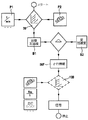
次いで、図2に示されている図表に基づいて、走行情報を出力するための方法が説明される。先ず、車両目標加速度B1が、車両20の実際の運転状態パラメータの内の少なくとも一つP1並びに走行抵抗パラメータの内の少なくとも一つP2から求められる。実際の運転状態パラメータP1としては、(例えば、フィルタリングされた或いは平滑化された)車速を用いることができるが、或いは又走行情報を求めるために、(フィルタリングされた或いは平滑化された)車両加速度、入れられたギヤに関する情報(ギヤ情報)或いは選択された走行レンジを用いることもできる。更に、エンジン回転数、及びオプションとして車重、或いはトレーラーが牽引されている(トレーラー牽引運転)か否かという情報が考慮されることもある。
Next, a method for outputting traveling information will be described based on the chart shown in FIG. First, the vehicle target acceleration B1 is obtained from at least one P1 of actual driving state parameters of the
走行抵抗パラメータP2は、既に上に説明されたようにして送り込まれることができる。エネルギー消費的に最適な或いは最適化された目標加速度B1に関するデータは、格納されている或いは記憶されている特性マップを利用して得ることができ、この特性マップには、運転状態パラメータP1及び走行抵抗パラメータP2が送り込まれる。特性マップは、計算によって或いは実験的に求めることができる。 The running resistance parameter P2 can be fed in as already described above. Data relating to the target acceleration B1 that is optimal or optimized in terms of energy consumption can be obtained by using a stored or stored characteristic map, which includes the driving state parameter P1 and the traveling Resistance parameter P2 is fed. The characteristic map can be obtained by calculation or experimentally.
ここで路面勾配の依存性が重要である。何故なら、勾配によって加速状態がエネルギー消費に対して平面の場合とは異なる影響を与えるからである。例えば、山下り走行の場合には、正の加速度が燃費に対して正の影響を与える。しかしながら、山登り走行の場合には、僅かな減速度がエネルギー消費に関して有利となる。このことが燃費的に最適な目標加速度B1の測定の際に、格納されている特性マップによって考慮されることがある。 Here, the dependency of the road gradient is important. This is because the gradient affects the energy consumption differently from the planar case due to the gradient. For example, in the case of traveling downhill, positive acceleration has a positive effect on fuel consumption. However, in the case of hill climbing, a slight deceleration is advantageous with regard to energy consumption. This may be taken into account by the stored characteristic map when measuring the target acceleration B1 that is optimal in terms of fuel consumption.
最適な車両目標加速度B1の測定の後に、走行情報INFが車両実加速度B2に応じて生成されるが、この走行情報INFは、その時の走行状況下における燃費的に最適な走行状態を指示しているので、ドライバーは、この情報から、この走行状態を実現するために、自分が車を加速或いは減速させるべきか否かということを知ることができる。 After the optimal vehicle target acceleration B1 is measured, the travel information INF is generated according to the vehicle actual acceleration B2. The travel information INF indicates the optimal travel state in terms of fuel consumption under the current travel conditions. Therefore, the driver can know from this information whether or not he / she should accelerate or decelerate the vehicle in order to realize this driving state.
求められた目標加速度B1は、例えば走行情報生成装置80に送られる。更に、走行情報生成装置80には、その時の車両実加速度B2が、例えばデータバス60を通して、伝えられる。二つの加速度値、即ち車両目標加速度B1と車両実加速度B2に応じて、それ等の値から、その時に可能な、エネルギー消費的に最適な走行状態を指示している走行情報INFが生成される。このことは、好ましくは数学的演算によって、例えば二つの加速度パラメータB1、B2の差の形成或いは除算によって、行われる。
仮に、例えば差の形成の結果がゼロに等しくない場合には、車両のその時の加速とは異なる加速が有効となる。同じことは、除算の結果が1に等しくない場合にも当てはまる。どのように加速すべきかという指示は、実加速度対目標加速度の比を表わしている結果から直接引き出すことができる。目標加速度B1を実加速度B2で除した際の結果が、例えば1よりも大きい場合には、ドライバーは加速すべきであろうし、結果が1よりも小さい場合には、ドライバーは減速すべきであろう。目標加速度からの実加速度の減算の場合には、マイナスの結果が負の加速度の可能性を、プラスの結果が正の加速度の可能性を指示している。
The obtained target acceleration B1 is sent to the travel information generating device 80, for example. Further, the actual vehicle acceleration B2 at that time is transmitted to the travel information generation device 80 through the data bus 60, for example. In accordance with the two acceleration values, that is, the vehicle target acceleration B1 and the vehicle actual acceleration B2, driving information INF indicating the optimal driving state in terms of energy consumption that is possible at that time is generated. . This is preferably done by mathematical operations, for example by forming or dividing the difference between the two acceleration parameters B1, B2.
If, for example, the result of the difference formation is not equal to zero, an acceleration different from the current acceleration of the vehicle is effective. The same is true when the result of the division is not equal to one. An indication of how to accelerate can be derived directly from the results representing the ratio of actual acceleration to target acceleration. If the result of dividing the target acceleration B1 by the actual acceleration B2 is greater than 1, for example, the driver should accelerate, and if the result is less than 1, the driver should decelerate. Let's go. In the case of subtracting the actual acceleration from the target acceleration, a negative result indicates the possibility of negative acceleration, and a positive result indicates the possibility of positive acceleration.
例えば上記の比較によって、生成された走行情報INFが結果として提供される。この走行情報INFは、燃費的に最適な走行状態が可能であるか否かについての表示を行い、更に、どのようにしてそのような走行状態を得るべきかということを指示する。それは、減速によって或いは加速によって実現することができる。しかしながら又、目標加速度B1と実加速度B2が一致し、その結果ドライバー110による如何なる操作も行われないということも考えられる。
For example, the generated traveling information INF is provided as a result of the above comparison. This travel information INF displays whether or not the optimal travel state in terms of fuel efficiency is possible, and further indicates how such a travel state should be obtained. It can be realized by deceleration or by acceleration. However, it is also conceivable that the target acceleration B1 and the actual acceleration B2 coincide with each other, and as a result, no operation by the
更に、得られた走行情報INFがドライバー110に対して出力される前になお、例えば勾配及び速度に応じた重み付け係数或いは正規化係数を用いて、例えば演算ユニット100で走行状態に応じて重み付けされることがある。これによって、例えば市街地走行やアウトバーン走行のような異なる状況に対応することができる。非常に高い速度或いは非常に低い速度の場合で、如何なる有効な指示もできないという時には、走行情報が、例えば中止されることがある。この目的のために、実速度と勾配から、同じく例えば演算ユニット100に格納されていることのできる、例えば一つ又は複数の特性マップと共に、重み付け係数を求めることができ、この係数を用いて、走行情報INFはより良い表示の目的のために、例えば対数的に重み付けされることができる。
Furthermore, before the obtained travel information INF is output to the
特に、重み付け係数については走行レンジに対する依存性も考慮される。その場合、走行レンジ(ギヤ)に応じて異なる、走行レンジに固有の、その時々の走行レンジの下での車両の加速特性やエネルギー消費を考慮した、特性マップを用いることができる。 In particular, the weighting factor also takes into account the dependence on the travel range. In this case, it is possible to use a characteristic map that takes into account the acceleration characteristics and energy consumption of the vehicle under the current travel range, which varies depending on the travel range (gear) and is specific to the travel range.
重み付けは、例えば生成された走行情報INFに重み付け係数を乗算することによって行うことができる。重み付け係数は、運転状態に応じて、例えば定速走行の場合には平坦地で一定にとどまっている速度からの最小のずれを指示するために、しかしながら勾配のきつい山地走行の場合には比較的大きな加速変動の場合に初めてシステム反応を開始させるために、非直線的な変化をすることができる。 The weighting can be performed, for example, by multiplying the generated travel information INF by a weighting coefficient. The weighting factor is dependent on the driving conditions, for example in order to indicate a minimum deviation from a constant speed on flat ground in the case of constant speed driving, however, Non-linear changes can be made to initiate the system response for the first time in the case of large acceleration fluctuations.
次いで、生成された、重み付けされた或いは重み付けされていない走行情報INFは、適当な手法でドライバー110に対して出力されるので、ドライバー110はそれに基づいて自分の走行挙動を燃費的に最適な走行状態の方向に変えることができる。この場合、ハンドリングについてのアドバイスを引き出すために、従来技術の場合のような出力された走行情報の手間の掛かる解釈は必要ではない。ドライバー110は、直接指示に基づいて加速を適合させることができる。
Next, the generated weighted or unweighted travel information INF is output to the
表示のために、走行情報INFは、この情報を出力する表示装置或いは出力装置90へ送られる。その際、走行情報INFは、視覚的及び/又は触覚的及び/又は聴覚的信号として形成されて出力されることができる。 For display, the travel information INF is sent to a display device or output device 90 that outputs this information. In this case, the driving information INF can be formed and output as a visual and / or tactile and / or audio signal.
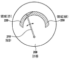
例えば、図3に示されている、指針210を用いて加速すべきか或いは減速すべきかについて指示する丸形の計器200を用いることができる。そのために計器の上の、例えば赤または緑に着色されているカラー識別された領域220、230を用いることができる。赤い領域220は、例えばドライバー110は平坦地の定速走行で不必要に加速している時のように、不経済な加速を示している。それに対して、緑の領域230は、例えばドライバー110が比較的燃費的に有利に走っているということを示している。追加として、車両20が減速されるが、走行状況に応じて異なる評価を受けることができるということを示す、第三の、例えば黄色の領域(図示されていない)を考えることができる。ドライバー110が、例えば不注意によって一時的に減速するという場合には、これは不利となる。ドライバー110が意図的に減速しようという場合には、これは勿論燃費にとってプラスとなる。
For example, a
更に、例えば出力信号は、触覚的信号として、車両20のアクセルペダル或いはハンドル等を通じて指示されることができる。可能な信号の形態には、振動、走行状態に応じた反力の感触、一つ又は複数のパルス等が考えられるであろう。
Further, for example, the output signal can be instructed as a tactile signal through an accelerator pedal or a handle of the
出力は又、聴覚的に、例えば信号音、信号音列、連続音等によって行うこともできる。その際、その聴覚的信号を、周波数に基づいて、加速或いは減速されるべきかということを知ることができるように形成することが考えられる。 The output can also be made audibly, for example with a signal sound, a signal sound train, a continuous sound, etc. At that time, it is conceivable to form the auditory signal so that it can be known whether it should be accelerated or decelerated based on the frequency.
特に、走行情報を出力するためのこの方法は、定速走行の際に、それ故ある程度の時間の間速度を(少なくともほゞ)一定に保持するように努める時に、使用するのに適している。その場合に、ドライバー110は、平坦地での走行の際に避けることのできる加速変動について直接指示されることができる。そのために、例えば特別に精密な分解能を持つ重み付け係数を選択することができる。登り或いは下りのある土地を走る際には、燃費的に最適な加速及び減速の手法は、勾配に合わせて提案される。
In particular, this method for outputting driving information is suitable for use when driving at a constant speed and therefore trying to keep the speed constant (at least approximately) for some time. . In that case, the
本発明の方法は、二つのシフトポイントの間の加速過程の中でも、燃費的に最も有利な走行状態、特に燃費的に最も有利な加速を信号表示するのに適している。その際、シフトポイントというのは、クラッチが繋がれ或いは遮断される時点を意味している。従って、本例の場合には、この方法は、好ましくは、一つのギヤ(走行レンジ)に入れるためのクラッチの結合から次の、もう一つの走行レンジ或いはニュートラルへの挿入のためのクラッチ遮断までの間の加速過程での中で適切に利用されることができる。ドライバー110は、随意に選択された走行運転状態で、ギヤ(走行レンジ)の挿入から自分の加速を燃費的に最も有利に又場合によっては目的に合わせて適合させることができる。クラッチを遮断した運転状態(アイドリング)では、より有利な燃費の可能性の信号表示を取りやめることができる。
The method of the present invention is suitable for displaying a signal indicating the most advantageous fuel economy driving state, particularly the most fuel efficient acceleration, in the acceleration process between two shift points. In this case, the shift point means a point in time when the clutch is engaged or disconnected. Thus, in the present example, this method is preferably from the coupling of a clutch for entering one gear (travel range) to the next clutch disengagement for insertion into another travel range or neutral. Can be used appropriately in the acceleration process during. The
オプションとして、本発明に基づく方法に関する機能或いはシステムは、車の中でオンオフすることができる。この操作は、例えばエコモード或いはスポーツモードと結び付けて行うことができる。 As an option, the functions or systems relating to the method according to the invention can be switched on and off in the car. This operation can be performed in conjunction with, for example, the eco mode or the sport mode.
10 本発明に基づく方法を実施するための装置
20 車両
30 測定装置
40 制御装置
50 駆動エンジン
60 データバス
70 センサ装置
80 走行情報生成装置
90 出力装置
100 演算ユニット
110 ドライバー
200 計器
210 指針
220 領域(赤)
230 領域(緑)
B1(Soll) 車両目標加速度
B2(Ist) 車両実加速度
10 Device for carrying out the method according to the
230 area (green)
B1 (Soll) Vehicle target acceleration B2 (Ist) Vehicle actual acceleration
Claims (10)
車両の実際の運転状態パラメータの内の少なくとも一つ(P1)並びに走行抵抗パラメータの内の少なくとも一つ(P2)に応じて燃費的に最適な車両目標加速度(B1)を測定するステップと、
車両実加速度(B2)を測定するステップと、
測定された車両目標加速度(B1)と車両実加速度(B2)とに応じて走行情報INFを生成するステップと、
走行情報(INF)を出力するステップと、
を含むことを特徴とする走行情報を出力するための方法。 In a method for outputting travel information (INF), instructing a driver of a vehicle (20) an optimal travel state in terms of energy consumption,
Measuring the optimum vehicle target acceleration (B1) in terms of fuel consumption according to at least one of the actual driving state parameters (P1) of the vehicle and at least one of the driving resistance parameters (P2);
Measuring the vehicle actual acceleration (B2);
Generating travel information INF according to the measured vehicle target acceleration (B1) and actual vehicle acceleration (B2);
Outputting travel information (INF);
A method for outputting travel information characterized by comprising:
車の実際の運転状態パラメータ(P1)の内の少なくとも一つ並びに走行抵抗パラメータ(P2)の内の少なくとも一つに応じて燃費的に最適な車両目標加速度(B1)を測定するための測定装置(30)と、
車両実加速度(B2)を測定するためのセンサ装置(70)と、
測定された車両目標加速度(B1)及び車両実加速度(B2)に応じて走行情報(INF)を生成するための装置(80)と、
走行情報(INF)を出力するための出力装置(90)と、
を備えたことを特徴とする走行情報を出力するための装置。 In the device (10) for outputting travel information (INF) that instructs the driver of the car (20) the optimal travel state in terms of energy consumption,
Measuring device for measuring the optimum vehicle target acceleration (B1) in terms of fuel consumption according to at least one of the actual driving state parameters (P1) of the vehicle and at least one of the running resistance parameters (P2) (30),
A sensor device (70) for measuring the actual vehicle acceleration (B2);
An apparatus (80) for generating travel information (INF) in response to the measured vehicle target acceleration (B1) and actual vehicle acceleration (B2);
An output device (90) for outputting travel information (INF);
A device for outputting travel information characterized by comprising:
Applications Claiming Priority (1)
| Application Number | Priority Date | Filing Date | Title |
|---|---|---|---|
| DE102008054703A DE102008054703A1 (en) | 2008-12-16 | 2008-12-16 | Method and device for outputting a driving information in a motor vehicle indicative of an energy-efficient acceleration possibility |
Publications (1)
| Publication Number | Publication Date |
|---|---|
| JP2010143567A true JP2010143567A (en) | 2010-07-01 |
Family
ID=42168331
Family Applications (1)
| Application Number | Title | Priority Date | Filing Date |
|---|---|---|---|
| JP2009282377A Pending JP2010143567A (en) | 2008-12-16 | 2009-12-14 | Method and device for outputting travel information |
Country Status (3)
| Country | Link |
|---|---|
| US (1) | US9079588B2 (en) |
| JP (1) | JP2010143567A (en) |
| DE (1) | DE102008054703A1 (en) |
Cited By (1)
| Publication number | Priority date | Publication date | Assignee | Title |
|---|---|---|---|---|
| JP2012210928A (en) * | 2011-03-23 | 2012-11-01 | Honda Access Corp | Fuel efficient driving support device |
Families Citing this family (7)
| Publication number | Priority date | Publication date | Assignee | Title |
|---|---|---|---|---|
| JP5585229B2 (en) * | 2010-06-16 | 2014-09-10 | 富士通株式会社 | Vehicle behavior estimation apparatus, program, and method |
| DE102010049912A1 (en) | 2010-10-28 | 2011-06-30 | Daimler AG, 70327 | Method for informing driver of motor vehicle about power reserve available in hybrid drive train, involves controlling functions of engine, traction drive and energy storage are controlled by control unit |
| US20130143181A1 (en) * | 2011-12-05 | 2013-06-06 | Ford Global Technologies, Llc | In-vehicle training system for teaching fuel economy |
| DE102014014308A1 (en) | 2014-09-25 | 2016-03-31 | Steffen Knöfler | Method for determining action-guiding formats of fuel consumption |
| CN105774595B (en) * | 2016-03-09 | 2018-06-29 | 广汽本田汽车有限公司 | Energy-saving acceleration method and device for electric vehicle |
| CN113099418B (en) * | 2021-03-26 | 2022-08-16 | 深圳供电局有限公司 | Optimization method of block chain task for data transmission of Internet of vehicles |
| CN114228720A (en) * | 2021-12-22 | 2022-03-25 | 阿波罗智联(北京)科技有限公司 | Energy saving method, device, equipment and storage medium for running vehicle |
Citations (4)
| Publication number | Priority date | Publication date | Assignee | Title |
|---|---|---|---|---|
| JPS62146735A (en) * | 1985-12-21 | 1987-06-30 | Toyota Motor Corp | Drive output control method for vehicle |
| JP2005076772A (en) * | 2003-09-01 | 2005-03-24 | Nissan Motor Co Ltd | Preceding vehicle following travel control device |
| JP2006076415A (en) * | 2004-09-09 | 2006-03-23 | Nissan Diesel Motor Co Ltd | Fuel saving operation evaluating system |
| JP2008239130A (en) * | 2007-03-29 | 2008-10-09 | Denso Corp | Control device for vehicle |
Family Cites Families (3)
| Publication number | Priority date | Publication date | Assignee | Title |
|---|---|---|---|---|
| US6092021A (en) * | 1997-12-01 | 2000-07-18 | Freightliner Corporation | Fuel use efficiency system for a vehicle for assisting the driver to improve fuel economy |
| US7024306B2 (en) * | 2003-07-24 | 2006-04-04 | Miyama, Inc. | Evaluation system for vehicle operating conditions and evaluation method thereof |
| US7522990B2 (en) * | 2005-06-08 | 2009-04-21 | General Electric Company | System and method for improved train handling and fuel consumption |
-
2008
- 2008-12-16 DE DE102008054703A patent/DE102008054703A1/en not_active Ceased
-
2009
- 2009-11-11 US US12/616,404 patent/US9079588B2/en not_active Expired - Fee Related
- 2009-12-14 JP JP2009282377A patent/JP2010143567A/en active Pending
Patent Citations (4)
| Publication number | Priority date | Publication date | Assignee | Title |
|---|---|---|---|---|
| JPS62146735A (en) * | 1985-12-21 | 1987-06-30 | Toyota Motor Corp | Drive output control method for vehicle |
| JP2005076772A (en) * | 2003-09-01 | 2005-03-24 | Nissan Motor Co Ltd | Preceding vehicle following travel control device |
| JP2006076415A (en) * | 2004-09-09 | 2006-03-23 | Nissan Diesel Motor Co Ltd | Fuel saving operation evaluating system |
| JP2008239130A (en) * | 2007-03-29 | 2008-10-09 | Denso Corp | Control device for vehicle |
Cited By (1)
| Publication number | Priority date | Publication date | Assignee | Title |
|---|---|---|---|---|
| JP2012210928A (en) * | 2011-03-23 | 2012-11-01 | Honda Access Corp | Fuel efficient driving support device |
Also Published As
| Publication number | Publication date |
|---|---|
| DE102008054703A1 (en) | 2010-06-17 |
| US9079588B2 (en) | 2015-07-14 |
| US20100152956A1 (en) | 2010-06-17 |
Similar Documents
| Publication | Publication Date | Title |
|---|---|---|
| JP7294272B2 (en) | Electric car | |
| JP7468759B2 (en) | Electric car | |
| US11302209B2 (en) | Vehicle driver feedback system and corresponding method | |
| JP2010143567A (en) | Method and device for outputting travel information | |
| CN102224362B (en) | Gear feedback system | |
| JP6222194B2 (en) | Driving force control device | |
| CN114056114A (en) | Electric automobile | |
| CN102224528B (en) | Slope feedback device | |
| JP2024038489A (en) | Electric car | |
| US10703377B2 (en) | Method and device for determining a measure of brake system usage during operation of a vehicle | |
| EP4574572A1 (en) | Vehicle management system and battery electric vehicle | |
| US7769520B2 (en) | Tractive force map | |
| JPH04272571A (en) | Shift change controller for automobile | |
| KR102577788B1 (en) | A system for calculating the minimum torque at the wheels of a motor vehicle and a system for using this calculation system to determine when to lift the foot off the accelerator. | |
| JP2017039462A (en) | Control device for vehicle display device | |
| EP4563398A1 (en) | Vehicle management system and battery electric vehicle | |
| EP4600949A1 (en) | Vehicle management system and battery electric vehicle | |
| JP2012012975A (en) | Fuel saving driving evaluation device | |
| KR20250133203A (en) | Electric vehicle |
Legal Events
| Date | Code | Title | Description |
|---|---|---|---|
| A621 | Written request for application examination |
Free format text: JAPANESE INTERMEDIATE CODE: A621 Effective date: 20121207 |
|
| A977 | Report on retrieval |
Free format text: JAPANESE INTERMEDIATE CODE: A971007 Effective date: 20140115 |
|
| A131 | Notification of reasons for refusal |
Free format text: JAPANESE INTERMEDIATE CODE: A131 Effective date: 20140124 |
|
| A601 | Written request for extension of time |
Free format text: JAPANESE INTERMEDIATE CODE: A601 Effective date: 20140422 |
|
| A602 | Written permission of extension of time |
Free format text: JAPANESE INTERMEDIATE CODE: A602 Effective date: 20140425 |
|
| A521 | Request for written amendment filed |
Free format text: JAPANESE INTERMEDIATE CODE: A523 Effective date: 20140602 |
|
| A02 | Decision of refusal |
Free format text: JAPANESE INTERMEDIATE CODE: A02 Effective date: 20141118 |